EP0863359A1 - Method and apparatus for manufacturing a hose for lining of pipelines and channel systems - Google Patents
Method and apparatus for manufacturing a hose for lining of pipelines and channel systems Download PDFInfo
- Publication number
- EP0863359A1 EP0863359A1 EP98100356A EP98100356A EP0863359A1 EP 0863359 A1 EP0863359 A1 EP 0863359A1 EP 98100356 A EP98100356 A EP 98100356A EP 98100356 A EP98100356 A EP 98100356A EP 0863359 A1 EP0863359 A1 EP 0863359A1
- Authority
- EP
- European Patent Office
- Prior art keywords
- edges
- fiber
- hose
- resin
- strip
- Prior art date
- Legal status (The legal status is an assumption and is not a legal conclusion. Google has not performed a legal analysis and makes no representation as to the accuracy of the status listed.)
- Withdrawn
Links
Images


Classifications
-
- F—MECHANICAL ENGINEERING; LIGHTING; HEATING; WEAPONS; BLASTING
- F16—ENGINEERING ELEMENTS AND UNITS; GENERAL MEASURES FOR PRODUCING AND MAINTAINING EFFECTIVE FUNCTIONING OF MACHINES OR INSTALLATIONS; THERMAL INSULATION IN GENERAL
- F16L—PIPES; JOINTS OR FITTINGS FOR PIPES; SUPPORTS FOR PIPES, CABLES OR PROTECTIVE TUBING; MEANS FOR THERMAL INSULATION IN GENERAL
- F16L55/00—Devices or appurtenances for use in, or in connection with, pipes or pipe systems
- F16L55/16—Devices for covering leaks in pipes or hoses, e.g. hose-menders
- F16L55/162—Devices for covering leaks in pipes or hoses, e.g. hose-menders from inside the pipe
- F16L55/165—Devices for covering leaks in pipes or hoses, e.g. hose-menders from inside the pipe a pipe or flexible liner being inserted in the damaged section
- F16L55/1656—Devices for covering leaks in pipes or hoses, e.g. hose-menders from inside the pipe a pipe or flexible liner being inserted in the damaged section materials for flexible liners
-
- B—PERFORMING OPERATIONS; TRANSPORTING
- B29—WORKING OF PLASTICS; WORKING OF SUBSTANCES IN A PLASTIC STATE IN GENERAL
- B29C—SHAPING OR JOINING OF PLASTICS; SHAPING OF MATERIAL IN A PLASTIC STATE, NOT OTHERWISE PROVIDED FOR; AFTER-TREATMENT OF THE SHAPED PRODUCTS, e.g. REPAIRING
- B29C53/00—Shaping by bending, folding, twisting, straightening or flattening; Apparatus therefor
- B29C53/36—Bending and joining, e.g. for making hollow articles
- B29C53/38—Bending and joining, e.g. for making hollow articles by bending sheets or strips at right angles to the longitudinal axis of the article being formed and joining the edges
- B29C53/385—Bending and joining, e.g. for making hollow articles by bending sheets or strips at right angles to the longitudinal axis of the article being formed and joining the edges using several sheets to form the circumference
-
- B—PERFORMING OPERATIONS; TRANSPORTING
- B29—WORKING OF PLASTICS; WORKING OF SUBSTANCES IN A PLASTIC STATE IN GENERAL
- B29C—SHAPING OR JOINING OF PLASTICS; SHAPING OF MATERIAL IN A PLASTIC STATE, NOT OTHERWISE PROVIDED FOR; AFTER-TREATMENT OF THE SHAPED PRODUCTS, e.g. REPAIRING
- B29C65/00—Joining or sealing of preformed parts, e.g. welding of plastics materials; Apparatus therefor
- B29C65/02—Joining or sealing of preformed parts, e.g. welding of plastics materials; Apparatus therefor by heating, with or without pressure
- B29C65/10—Joining or sealing of preformed parts, e.g. welding of plastics materials; Apparatus therefor by heating, with or without pressure using hot gases (e.g. combustion gases) or flames coming in contact with at least one of the parts to be joined
- B29C65/103—Joining or sealing of preformed parts, e.g. welding of plastics materials; Apparatus therefor by heating, with or without pressure using hot gases (e.g. combustion gases) or flames coming in contact with at least one of the parts to be joined direct heating both surfaces to be joined
-
- B—PERFORMING OPERATIONS; TRANSPORTING
- B29—WORKING OF PLASTICS; WORKING OF SUBSTANCES IN A PLASTIC STATE IN GENERAL
- B29C—SHAPING OR JOINING OF PLASTICS; SHAPING OF MATERIAL IN A PLASTIC STATE, NOT OTHERWISE PROVIDED FOR; AFTER-TREATMENT OF THE SHAPED PRODUCTS, e.g. REPAIRING
- B29C65/00—Joining or sealing of preformed parts, e.g. welding of plastics materials; Apparatus therefor
- B29C65/02—Joining or sealing of preformed parts, e.g. welding of plastics materials; Apparatus therefor by heating, with or without pressure
- B29C65/18—Joining or sealing of preformed parts, e.g. welding of plastics materials; Apparatus therefor by heating, with or without pressure using heated tools
- B29C65/20—Joining or sealing of preformed parts, e.g. welding of plastics materials; Apparatus therefor by heating, with or without pressure using heated tools with direct contact, e.g. using "mirror"
- B29C65/2007—Joining or sealing of preformed parts, e.g. welding of plastics materials; Apparatus therefor by heating, with or without pressure using heated tools with direct contact, e.g. using "mirror" characterised by the type of welding mirror
- B29C65/203—Joining or sealing of preformed parts, e.g. welding of plastics materials; Apparatus therefor by heating, with or without pressure using heated tools with direct contact, e.g. using "mirror" characterised by the type of welding mirror being several single mirrors, e.g. not mounted on the same tool
-
- B—PERFORMING OPERATIONS; TRANSPORTING
- B29—WORKING OF PLASTICS; WORKING OF SUBSTANCES IN A PLASTIC STATE IN GENERAL
- B29C—SHAPING OR JOINING OF PLASTICS; SHAPING OF MATERIAL IN A PLASTIC STATE, NOT OTHERWISE PROVIDED FOR; AFTER-TREATMENT OF THE SHAPED PRODUCTS, e.g. REPAIRING
- B29C65/00—Joining or sealing of preformed parts, e.g. welding of plastics materials; Apparatus therefor
- B29C65/02—Joining or sealing of preformed parts, e.g. welding of plastics materials; Apparatus therefor by heating, with or without pressure
- B29C65/18—Joining or sealing of preformed parts, e.g. welding of plastics materials; Apparatus therefor by heating, with or without pressure using heated tools
- B29C65/24—Joining or sealing of preformed parts, e.g. welding of plastics materials; Apparatus therefor by heating, with or without pressure using heated tools characterised by the means for heating the tool
- B29C65/30—Electrical means
- B29C65/305—Electrical means involving the use of cartridge heaters
-
- B—PERFORMING OPERATIONS; TRANSPORTING
- B29—WORKING OF PLASTICS; WORKING OF SUBSTANCES IN A PLASTIC STATE IN GENERAL
- B29C—SHAPING OR JOINING OF PLASTICS; SHAPING OF MATERIAL IN A PLASTIC STATE, NOT OTHERWISE PROVIDED FOR; AFTER-TREATMENT OF THE SHAPED PRODUCTS, e.g. REPAIRING
- B29C65/00—Joining or sealing of preformed parts, e.g. welding of plastics materials; Apparatus therefor
- B29C65/48—Joining or sealing of preformed parts, e.g. welding of plastics materials; Apparatus therefor using adhesives, i.e. using supplementary joining material; solvent bonding
- B29C65/52—Joining or sealing of preformed parts, e.g. welding of plastics materials; Apparatus therefor using adhesives, i.e. using supplementary joining material; solvent bonding characterised by the way of applying the adhesive
- B29C65/524—Joining or sealing of preformed parts, e.g. welding of plastics materials; Apparatus therefor using adhesives, i.e. using supplementary joining material; solvent bonding characterised by the way of applying the adhesive by applying the adhesive from an outlet device in contact with, or almost in contact with, the surface of the part to be joined
-
- B—PERFORMING OPERATIONS; TRANSPORTING
- B29—WORKING OF PLASTICS; WORKING OF SUBSTANCES IN A PLASTIC STATE IN GENERAL
- B29C—SHAPING OR JOINING OF PLASTICS; SHAPING OF MATERIAL IN A PLASTIC STATE, NOT OTHERWISE PROVIDED FOR; AFTER-TREATMENT OF THE SHAPED PRODUCTS, e.g. REPAIRING
- B29C66/00—General aspects of processes or apparatus for joining preformed parts
- B29C66/01—General aspects dealing with the joint area or with the area to be joined
- B29C66/05—Particular design of joint configurations
- B29C66/10—Particular design of joint configurations particular design of the joint cross-sections
- B29C66/11—Joint cross-sections comprising a single joint-segment, i.e. one of the parts to be joined comprising a single joint-segment in the joint cross-section
- B29C66/112—Single lapped joints
- B29C66/1122—Single lap to lap joints, i.e. overlap joints
-
- B—PERFORMING OPERATIONS; TRANSPORTING
- B29—WORKING OF PLASTICS; WORKING OF SUBSTANCES IN A PLASTIC STATE IN GENERAL
- B29C—SHAPING OR JOINING OF PLASTICS; SHAPING OF MATERIAL IN A PLASTIC STATE, NOT OTHERWISE PROVIDED FOR; AFTER-TREATMENT OF THE SHAPED PRODUCTS, e.g. REPAIRING
- B29C66/00—General aspects of processes or apparatus for joining preformed parts
- B29C66/01—General aspects dealing with the joint area or with the area to be joined
- B29C66/05—Particular design of joint configurations
- B29C66/20—Particular design of joint configurations particular design of the joint lines, e.g. of the weld lines
- B29C66/22—Particular design of joint configurations particular design of the joint lines, e.g. of the weld lines said joint lines being in the form of recurring patterns
- B29C66/221—Particular design of joint configurations particular design of the joint lines, e.g. of the weld lines said joint lines being in the form of recurring patterns being in the form of a sinusoidal wave
-
- B—PERFORMING OPERATIONS; TRANSPORTING
- B29—WORKING OF PLASTICS; WORKING OF SUBSTANCES IN A PLASTIC STATE IN GENERAL
- B29C—SHAPING OR JOINING OF PLASTICS; SHAPING OF MATERIAL IN A PLASTIC STATE, NOT OTHERWISE PROVIDED FOR; AFTER-TREATMENT OF THE SHAPED PRODUCTS, e.g. REPAIRING
- B29C66/00—General aspects of processes or apparatus for joining preformed parts
- B29C66/01—General aspects dealing with the joint area or with the area to be joined
- B29C66/05—Particular design of joint configurations
- B29C66/20—Particular design of joint configurations particular design of the joint lines, e.g. of the weld lines
- B29C66/23—Particular design of joint configurations particular design of the joint lines, e.g. of the weld lines said joint lines being multiple and parallel or being in the form of tessellations
- B29C66/232—Particular design of joint configurations particular design of the joint lines, e.g. of the weld lines said joint lines being multiple and parallel or being in the form of tessellations said joint lines being multiple and parallel, i.e. the joint being formed by several parallel joint lines
-
- B—PERFORMING OPERATIONS; TRANSPORTING
- B29—WORKING OF PLASTICS; WORKING OF SUBSTANCES IN A PLASTIC STATE IN GENERAL
- B29C—SHAPING OR JOINING OF PLASTICS; SHAPING OF MATERIAL IN A PLASTIC STATE, NOT OTHERWISE PROVIDED FOR; AFTER-TREATMENT OF THE SHAPED PRODUCTS, e.g. REPAIRING
- B29C66/00—General aspects of processes or apparatus for joining preformed parts
- B29C66/40—General aspects of joining substantially flat articles, e.g. plates, sheets or web-like materials; Making flat seams in tubular or hollow articles; Joining single elements to substantially flat surfaces
- B29C66/41—Joining substantially flat articles ; Making flat seams in tubular or hollow articles
- B29C66/43—Joining a relatively small portion of the surface of said articles
- B29C66/432—Joining a relatively small portion of the surface of said articles for making tubular articles or closed loops, e.g. by joining several sheets ; for making hollow articles or hollow preforms
- B29C66/4322—Joining a relatively small portion of the surface of said articles for making tubular articles or closed loops, e.g. by joining several sheets ; for making hollow articles or hollow preforms by joining a single sheet to itself
-
- B—PERFORMING OPERATIONS; TRANSPORTING
- B29—WORKING OF PLASTICS; WORKING OF SUBSTANCES IN A PLASTIC STATE IN GENERAL
- B29C—SHAPING OR JOINING OF PLASTICS; SHAPING OF MATERIAL IN A PLASTIC STATE, NOT OTHERWISE PROVIDED FOR; AFTER-TREATMENT OF THE SHAPED PRODUCTS, e.g. REPAIRING
- B29C66/00—General aspects of processes or apparatus for joining preformed parts
- B29C66/40—General aspects of joining substantially flat articles, e.g. plates, sheets or web-like materials; Making flat seams in tubular or hollow articles; Joining single elements to substantially flat surfaces
- B29C66/49—Internally supporting the, e.g. tubular, article during joining
-
- B—PERFORMING OPERATIONS; TRANSPORTING
- B29—WORKING OF PLASTICS; WORKING OF SUBSTANCES IN A PLASTIC STATE IN GENERAL
- B29C—SHAPING OR JOINING OF PLASTICS; SHAPING OF MATERIAL IN A PLASTIC STATE, NOT OTHERWISE PROVIDED FOR; AFTER-TREATMENT OF THE SHAPED PRODUCTS, e.g. REPAIRING
- B29C66/00—General aspects of processes or apparatus for joining preformed parts
- B29C66/70—General aspects of processes or apparatus for joining preformed parts characterised by the composition, physical properties or the structure of the material of the parts to be joined; Joining with non-plastics material
- B29C66/72—General aspects of processes or apparatus for joining preformed parts characterised by the composition, physical properties or the structure of the material of the parts to be joined; Joining with non-plastics material characterised by the structure of the material of the parts to be joined
- B29C66/723—General aspects of processes or apparatus for joining preformed parts characterised by the composition, physical properties or the structure of the material of the parts to be joined; Joining with non-plastics material characterised by the structure of the material of the parts to be joined being multi-layered
-
- B—PERFORMING OPERATIONS; TRANSPORTING
- B29—WORKING OF PLASTICS; WORKING OF SUBSTANCES IN A PLASTIC STATE IN GENERAL
- B29C—SHAPING OR JOINING OF PLASTICS; SHAPING OF MATERIAL IN A PLASTIC STATE, NOT OTHERWISE PROVIDED FOR; AFTER-TREATMENT OF THE SHAPED PRODUCTS, e.g. REPAIRING
- B29C66/00—General aspects of processes or apparatus for joining preformed parts
- B29C66/70—General aspects of processes or apparatus for joining preformed parts characterised by the composition, physical properties or the structure of the material of the parts to be joined; Joining with non-plastics material
- B29C66/73—General aspects of processes or apparatus for joining preformed parts characterised by the composition, physical properties or the structure of the material of the parts to be joined; Joining with non-plastics material characterised by the intensive physical properties of the material of the parts to be joined, by the optical properties of the material of the parts to be joined, by the extensive physical properties of the parts to be joined, by the state of the material of the parts to be joined or by the material of the parts to be joined being a thermoplastic or a thermoset
- B29C66/731—General aspects of processes or apparatus for joining preformed parts characterised by the composition, physical properties or the structure of the material of the parts to be joined; Joining with non-plastics material characterised by the intensive physical properties of the material of the parts to be joined, by the optical properties of the material of the parts to be joined, by the extensive physical properties of the parts to be joined, by the state of the material of the parts to be joined or by the material of the parts to be joined being a thermoplastic or a thermoset characterised by the intensive physical properties of the material of the parts to be joined
- B29C66/7311—Thermal properties
- B29C66/73115—Melting point
- B29C66/73116—Melting point of different melting point, i.e. the melting point of one of the parts to be joined being different from the melting point of the other part
-
- B—PERFORMING OPERATIONS; TRANSPORTING
- B29—WORKING OF PLASTICS; WORKING OF SUBSTANCES IN A PLASTIC STATE IN GENERAL
- B29C—SHAPING OR JOINING OF PLASTICS; SHAPING OF MATERIAL IN A PLASTIC STATE, NOT OTHERWISE PROVIDED FOR; AFTER-TREATMENT OF THE SHAPED PRODUCTS, e.g. REPAIRING
- B29C66/00—General aspects of processes or apparatus for joining preformed parts
- B29C66/80—General aspects of machine operations or constructions and parts thereof
- B29C66/83—General aspects of machine operations or constructions and parts thereof characterised by the movement of the joining or pressing tools
- B29C66/834—General aspects of machine operations or constructions and parts thereof characterised by the movement of the joining or pressing tools moving with the parts to be joined
- B29C66/8341—Roller, cylinder or drum types; Band or belt types; Ball types
- B29C66/83411—Roller, cylinder or drum types
-
- B—PERFORMING OPERATIONS; TRANSPORTING
- B29—WORKING OF PLASTICS; WORKING OF SUBSTANCES IN A PLASTIC STATE IN GENERAL
- B29C—SHAPING OR JOINING OF PLASTICS; SHAPING OF MATERIAL IN A PLASTIC STATE, NOT OTHERWISE PROVIDED FOR; AFTER-TREATMENT OF THE SHAPED PRODUCTS, e.g. REPAIRING
- B29C66/00—General aspects of processes or apparatus for joining preformed parts
- B29C66/80—General aspects of machine operations or constructions and parts thereof
- B29C66/84—Specific machine types or machines suitable for specific applications
- B29C66/843—Machines for making separate joints at the same time in different planes; Machines for making separate joints at the same time mounted in parallel or in series
- B29C66/8432—Machines for making separate joints at the same time mounted in parallel or in series
-
- B—PERFORMING OPERATIONS; TRANSPORTING
- B29—WORKING OF PLASTICS; WORKING OF SUBSTANCES IN A PLASTIC STATE IN GENERAL
- B29C—SHAPING OR JOINING OF PLASTICS; SHAPING OF MATERIAL IN A PLASTIC STATE, NOT OTHERWISE PROVIDED FOR; AFTER-TREATMENT OF THE SHAPED PRODUCTS, e.g. REPAIRING
- B29C66/00—General aspects of processes or apparatus for joining preformed parts
- B29C66/90—Measuring or controlling the joining process
- B29C66/91—Measuring or controlling the joining process by measuring or controlling the temperature, the heat or the thermal flux
- B29C66/912—Measuring or controlling the joining process by measuring or controlling the temperature, the heat or the thermal flux by measuring the temperature, the heat or the thermal flux
- B29C66/9121—Measuring or controlling the joining process by measuring or controlling the temperature, the heat or the thermal flux by measuring the temperature, the heat or the thermal flux by measuring the temperature
- B29C66/91211—Measuring or controlling the joining process by measuring or controlling the temperature, the heat or the thermal flux by measuring the temperature, the heat or the thermal flux by measuring the temperature with special temperature measurement means or methods
- B29C66/91212—Measuring or controlling the joining process by measuring or controlling the temperature, the heat or the thermal flux by measuring the temperature, the heat or the thermal flux by measuring the temperature with special temperature measurement means or methods involving measurement means being part of the welding jaws, e.g. integrated in the welding jaws
-
- B—PERFORMING OPERATIONS; TRANSPORTING
- B29—WORKING OF PLASTICS; WORKING OF SUBSTANCES IN A PLASTIC STATE IN GENERAL
- B29C—SHAPING OR JOINING OF PLASTICS; SHAPING OF MATERIAL IN A PLASTIC STATE, NOT OTHERWISE PROVIDED FOR; AFTER-TREATMENT OF THE SHAPED PRODUCTS, e.g. REPAIRING
- B29C66/00—General aspects of processes or apparatus for joining preformed parts
- B29C66/90—Measuring or controlling the joining process
- B29C66/91—Measuring or controlling the joining process by measuring or controlling the temperature, the heat or the thermal flux
- B29C66/914—Measuring or controlling the joining process by measuring or controlling the temperature, the heat or the thermal flux by controlling or regulating the temperature, the heat or the thermal flux
- B29C66/9141—Measuring or controlling the joining process by measuring or controlling the temperature, the heat or the thermal flux by controlling or regulating the temperature, the heat or the thermal flux by controlling or regulating the temperature
- B29C66/91431—Measuring or controlling the joining process by measuring or controlling the temperature, the heat or the thermal flux by controlling or regulating the temperature, the heat or the thermal flux by controlling or regulating the temperature the temperature being kept constant over time
-
- B—PERFORMING OPERATIONS; TRANSPORTING
- B29—WORKING OF PLASTICS; WORKING OF SUBSTANCES IN A PLASTIC STATE IN GENERAL
- B29C—SHAPING OR JOINING OF PLASTICS; SHAPING OF MATERIAL IN A PLASTIC STATE, NOT OTHERWISE PROVIDED FOR; AFTER-TREATMENT OF THE SHAPED PRODUCTS, e.g. REPAIRING
- B29C53/00—Shaping by bending, folding, twisting, straightening or flattening; Apparatus therefor
- B29C53/36—Bending and joining, e.g. for making hollow articles
- B29C53/38—Bending and joining, e.g. for making hollow articles by bending sheets or strips at right angles to the longitudinal axis of the article being formed and joining the edges
- B29C53/48—Bending and joining, e.g. for making hollow articles by bending sheets or strips at right angles to the longitudinal axis of the article being formed and joining the edges for articles of indefinite length, i.e. bending a strip progressively
-
- B—PERFORMING OPERATIONS; TRANSPORTING
- B29—WORKING OF PLASTICS; WORKING OF SUBSTANCES IN A PLASTIC STATE IN GENERAL
- B29C—SHAPING OR JOINING OF PLASTICS; SHAPING OF MATERIAL IN A PLASTIC STATE, NOT OTHERWISE PROVIDED FOR; AFTER-TREATMENT OF THE SHAPED PRODUCTS, e.g. REPAIRING
- B29C63/00—Lining or sheathing, i.e. applying preformed layers or sheathings of plastics; Apparatus therefor
- B29C63/26—Lining or sheathing of internal surfaces
- B29C63/34—Lining or sheathing of internal surfaces using tubular layers or sheathings
-
- B—PERFORMING OPERATIONS; TRANSPORTING
- B29—WORKING OF PLASTICS; WORKING OF SUBSTANCES IN A PLASTIC STATE IN GENERAL
- B29C—SHAPING OR JOINING OF PLASTICS; SHAPING OF MATERIAL IN A PLASTIC STATE, NOT OTHERWISE PROVIDED FOR; AFTER-TREATMENT OF THE SHAPED PRODUCTS, e.g. REPAIRING
- B29C66/00—General aspects of processes or apparatus for joining preformed parts
- B29C66/01—General aspects dealing with the joint area or with the area to be joined
- B29C66/02—Preparation of the material, in the area to be joined, prior to joining or welding
- B29C66/024—Thermal pre-treatments
- B29C66/0242—Heating, or preheating, e.g. drying
-
- B—PERFORMING OPERATIONS; TRANSPORTING
- B29—WORKING OF PLASTICS; WORKING OF SUBSTANCES IN A PLASTIC STATE IN GENERAL
- B29C—SHAPING OR JOINING OF PLASTICS; SHAPING OF MATERIAL IN A PLASTIC STATE, NOT OTHERWISE PROVIDED FOR; AFTER-TREATMENT OF THE SHAPED PRODUCTS, e.g. REPAIRING
- B29C66/00—General aspects of processes or apparatus for joining preformed parts
- B29C66/70—General aspects of processes or apparatus for joining preformed parts characterised by the composition, physical properties or the structure of the material of the parts to be joined; Joining with non-plastics material
- B29C66/71—General aspects of processes or apparatus for joining preformed parts characterised by the composition, physical properties or the structure of the material of the parts to be joined; Joining with non-plastics material characterised by the composition of the plastics material of the parts to be joined
-
- B—PERFORMING OPERATIONS; TRANSPORTING
- B29—WORKING OF PLASTICS; WORKING OF SUBSTANCES IN A PLASTIC STATE IN GENERAL
- B29C—SHAPING OR JOINING OF PLASTICS; SHAPING OF MATERIAL IN A PLASTIC STATE, NOT OTHERWISE PROVIDED FOR; AFTER-TREATMENT OF THE SHAPED PRODUCTS, e.g. REPAIRING
- B29C66/00—General aspects of processes or apparatus for joining preformed parts
- B29C66/70—General aspects of processes or apparatus for joining preformed parts characterised by the composition, physical properties or the structure of the material of the parts to be joined; Joining with non-plastics material
- B29C66/72—General aspects of processes or apparatus for joining preformed parts characterised by the composition, physical properties or the structure of the material of the parts to be joined; Joining with non-plastics material characterised by the structure of the material of the parts to be joined
- B29C66/723—General aspects of processes or apparatus for joining preformed parts characterised by the composition, physical properties or the structure of the material of the parts to be joined; Joining with non-plastics material characterised by the structure of the material of the parts to be joined being multi-layered
- B29C66/7232—General aspects of processes or apparatus for joining preformed parts characterised by the composition, physical properties or the structure of the material of the parts to be joined; Joining with non-plastics material characterised by the structure of the material of the parts to be joined being multi-layered comprising a non-plastics layer
- B29C66/72324—General aspects of processes or apparatus for joining preformed parts characterised by the composition, physical properties or the structure of the material of the parts to be joined; Joining with non-plastics material characterised by the structure of the material of the parts to be joined being multi-layered comprising a non-plastics layer consisting of inorganic materials not provided for in B29C66/72321 - B29C66/72322
- B29C66/72326—Glass
-
- B—PERFORMING OPERATIONS; TRANSPORTING
- B29—WORKING OF PLASTICS; WORKING OF SUBSTANCES IN A PLASTIC STATE IN GENERAL
- B29C—SHAPING OR JOINING OF PLASTICS; SHAPING OF MATERIAL IN A PLASTIC STATE, NOT OTHERWISE PROVIDED FOR; AFTER-TREATMENT OF THE SHAPED PRODUCTS, e.g. REPAIRING
- B29C66/00—General aspects of processes or apparatus for joining preformed parts
- B29C66/80—General aspects of machine operations or constructions and parts thereof
- B29C66/81—General aspects of the pressing elements, i.e. the elements applying pressure on the parts to be joined in the area to be joined, e.g. the welding jaws or clamps
- B29C66/818—General aspects of the pressing elements, i.e. the elements applying pressure on the parts to be joined in the area to be joined, e.g. the welding jaws or clamps characterised by the cooling constructional aspects, or by the thermal or electrical insulating or conducting constructional aspects of the welding jaws or of the clamps ; comprising means for compensating for the thermal expansion of the welding jaws or of the clamps
- B29C66/8182—General aspects of the pressing elements, i.e. the elements applying pressure on the parts to be joined in the area to be joined, e.g. the welding jaws or clamps characterised by the cooling constructional aspects, or by the thermal or electrical insulating or conducting constructional aspects of the welding jaws or of the clamps ; comprising means for compensating for the thermal expansion of the welding jaws or of the clamps characterised by the thermal insulating constructional aspects
- B29C66/81821—General aspects of the pressing elements, i.e. the elements applying pressure on the parts to be joined in the area to be joined, e.g. the welding jaws or clamps characterised by the cooling constructional aspects, or by the thermal or electrical insulating or conducting constructional aspects of the welding jaws or of the clamps ; comprising means for compensating for the thermal expansion of the welding jaws or of the clamps characterised by the thermal insulating constructional aspects of the welding jaws
-
- B—PERFORMING OPERATIONS; TRANSPORTING
- B29—WORKING OF PLASTICS; WORKING OF SUBSTANCES IN A PLASTIC STATE IN GENERAL
- B29C—SHAPING OR JOINING OF PLASTICS; SHAPING OF MATERIAL IN A PLASTIC STATE, NOT OTHERWISE PROVIDED FOR; AFTER-TREATMENT OF THE SHAPED PRODUCTS, e.g. REPAIRING
- B29C66/00—General aspects of processes or apparatus for joining preformed parts
- B29C66/90—Measuring or controlling the joining process
- B29C66/91—Measuring or controlling the joining process by measuring or controlling the temperature, the heat or the thermal flux
- B29C66/912—Measuring or controlling the joining process by measuring or controlling the temperature, the heat or the thermal flux by measuring the temperature, the heat or the thermal flux
- B29C66/9121—Measuring or controlling the joining process by measuring or controlling the temperature, the heat or the thermal flux by measuring the temperature, the heat or the thermal flux by measuring the temperature
-
- B—PERFORMING OPERATIONS; TRANSPORTING
- B29—WORKING OF PLASTICS; WORKING OF SUBSTANCES IN A PLASTIC STATE IN GENERAL
- B29L—INDEXING SCHEME ASSOCIATED WITH SUBCLASS B29C, RELATING TO PARTICULAR ARTICLES
- B29L2023/00—Tubular articles
- B29L2023/003—Tubular articles having irregular or rough surfaces
-
- B—PERFORMING OPERATIONS; TRANSPORTING
- B29—WORKING OF PLASTICS; WORKING OF SUBSTANCES IN A PLASTIC STATE IN GENERAL
- B29L—INDEXING SCHEME ASSOCIATED WITH SUBCLASS B29C, RELATING TO PARTICULAR ARTICLES
- B29L2023/00—Tubular articles
- B29L2023/005—Hoses, i.e. flexible
- B29L2023/006—Flexible liners
Definitions
- the invention relates to a method for producing a hose for the Lining of pipelines and sewer systems with at least one made of a fiber material, impregnable with a hardenable resin Inner layer, the edges of which lay on top of one another same or a different fiber strip on the circumference of the hose with at least one permanently connected in the longitudinal direction Overlap area and then with a outer film is impermeable to the resin.
- hoses are also referred to as "liners". Both their manufacture as well as their laying when renovating pipelines and Channel systems are complicated and time consuming, especially then when it comes to the manufacture and processing of hoses longer length.
- the load-bearing element is the after curing tubular closed layer made of the impregnated fiber material.
- the resin or fiber material must be as far as possible free of voids caused by air pockets but also arise from insufficient impregnation of the fiber material can.
- the resin can be cured either by heat, visible light or ultraviolet light.
- resin materials in the trade which accelerate curing can be mixed with activators and accelerators.
- Such hoses or liners can, for example, in a flat Condition moved into the redevelopment area and after the installation of so-called End caps inflated by a medium under pressure and pressed against the walls to be renovated.
- a another method of inserting the hose or liner is the so-called Invert or Evert.
- Invert or Evert In both cases it is impregnated Fiber material for the purpose of handling the hose on the outside from a gas-impermeable outer layer from a tubular Surround foil, which is of course also resin-tight.
- the invention is therefore based on the object of a method of the beginning Specify the type mentioned, which leads to a stable and flexible Pre-product leads to a final impregnation and easy to carry out is.
- the invention thus contains two alternatives to achieve the same object Solution ideas based on the same mechanical principle and both in a continuous process or in a kinematic reversal of motion are feasible and the sufficient strength of the Connect against shear stresses.
- the surface becomes between the fiber strips parallel contact surfaces a continuous, interrupted, iridescent or meandering, preferably narrow, trace of resin introduced, which penetrates sufficiently deep into the fiber strips without to destroy its fiber structure in the immediate vicinity of the Harzspur or sink marks, and the final impregnation is compatible or compatible with the impregnating resin and the micro currents not hindered in the impregnation.
- the feature b2) is based on the consideration that the higher melting Fibers keep their structure and the gaps, the fiber material So it doesn't "come in” or "sink".
- the low-melting ones Fibers soft or sticky and combine with the higher melting ones Fibers. It has surprisingly been found that the connection due to larger physical forces perpendicular to the contact surfaces can be separated by tearing out individual fibers, but that the Connection against tangential forces is quite strong enough to Survive finishing. Because the heating from the contact surface from, that is, from within, turns to both A falling temperature gradient at which the vast majority of the The fiber structure of the low-melting fibers is preserved.
- the invention is based on the joint consideration of the melting behavior the low-melting fibers, their gluing with the higher melting fibers with no substantial loss of porosity, so that there is no disruptive "falling in” of the fiber strips at the connection point. It can be assumed that the higher melting fibers here have a supporting function for the low-melting fibers.
- preliminary products for the final impregnation can be produced, which are stretchable in the radial direction, undesirable displacements, folding of edges and / or wrinkling of the Prevent fiber strips during transport and further processing and no porosity, capillaries (steam penetration) and cross-sectional weakening through seams or welds (so-called Topstitching or padding effect).
- This is the number of fiber strips - Seen in the circumferential direction and in the thickness - not limited. It will however emphasizes that the invention also consists in and then has an advantageous effect if only one on a hose circumference of 360 degrees Overlap point is provided and if there is only one inner layer is.
- the resin of the hardened resin strips is not dissolved or softened, such as. an adhesive that is a foreign substance, but rather goes an inseparable bond with the resin of the final impregnation. Finally, the resin strips do not hinder the resin flow or the Evacuation during the final impregnation. It is an irreversible one Process that cannot be canceled.
- connection point (s) in the circumferential direction of the hose is / are narrow in relation to the width of the respective Overlap area.
- Such a hose can be particularly advantageous from the start be provided with an inner tube, this is done in such a way that the at least one inner layer made of fiber material by one is placed around the inner tube impermeable to the resin and that the resin of the at least one overlap area after the Application is cured by energy radiation.
- the inner tube is an advantageous manufacturing aid for the Inner layer from the fiber material or from the fiber strips, and it is no longer necessary to pull an inner hose later.
- Manufacturing can be done with any number of overlap areas take place on the circumference of the inner layer, namely in that the. Inner layer with one another lying on at least one overlap point Wall parts is guided over a calibration body, and that after insertion the curable resin at each of the overlap points thereof Curing is carried out.
- the shelf can be from a simple work table, in an advantageous manner Way consist of a conveyor belt.
- the filing is also done indirectly, for example when there is an inner tube on the shelf located.
- This manufacturing method has the great advantage that the folding process always only takes place on top of the shelf. So it's not necessary - as in the prior art - fiber strips alternately from below above and then from top to bottom around the previously formed hose assembly fold around. This creates special problems with the Folding process on the bottom. The state of the art only deals with folding around without connecting the individual fiber strips.
- a further embodiment of the invention also enables the construction of the Inner layer made of more than one inner layer made of fiber material, namely by that successively at least two consisting of fiber material Inner layers are generated on the shelf and that the first inner layer before the application of the second and each further inner layer by 180 degrees is turned.
- the one to be brought in at the very end Impregnation resin resistant and impervious to it must be is proceeded in a particularly advantageous manner that a Outer film is used with a width that is larger than the circumference of the last inner layer made of fiber material, and that the outer film, coming from below, forming an overlap area around the folded at least one inner layer and welded in the overlap area becomes.
- the invention also relates to one according to the method described above and its variants manufactured hose, the essential Features of this hose are described in claims 20 to 26.
- the invention also relates to a device for producing a hose with at least one of at least one impregnable fiber strip existing inner layer for the lining of pipelines and sewer systems, with an at least substantially horizontal shelf and a transport device for the transport of the hose, with at least a supply roll, each with an impregnable fiber strip, the storage is feedable, and with means for folding around the strip edges.
- the transport device can differ not only in terms of manufacture wider hoses (the width refers to the flat-lying hose), but the setting options also lead to the fact that the overlap areas on the circumference offset from each other can be arranged.
- the individual options for this are described in the detailed description explained in more detail.
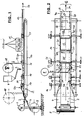
- Figures 1 and 2 is a first supply roll 1 with an inner tube 2 shown from a transparent film, which is carried out with or without seam can be and impermeable and resistant to curable resins is.
- This inner tube 2 becomes a shelf 3 when it is lying flat fed, which is designed as a continuously running conveyor belt 14.
- the Thickness ratios are not to scale.
- a first fiber strip is synchronized with this from a second supply roll 5 6 made of an impregnable with a curable resin and in Subtracted stretchable fiber material.
- the two edges 6a and 6b are placed around the inner tube 2 and thereby form two overlap areas 7a and 7b.
- the resin input can continuously iridescent or intermittent.
- the resin is in the form of so-called Resin traces 23 are each applied in a width that is less than the width of the overlap areas 7a and 7b and partially penetrates into the fiber material, which is indicated in Figure 3 by blackening.
- Figures 1 and 2 show a horizontal procedure and a device particularly suitable for this purpose, which requires little space and especially on different hose diameters and different spatial positions of the overlap areas 7a and 7b adjustable is.
- the first fiber strip 6 is deposited from below, that of the supply roll 5 comes and its width is greater than half the circumference or the width of the flat inner tube 2.
- slide rails 15 whose distance and relative position to the shelf 3 by handwheels 16 and Threaded spindles 17 is independently adjustable, the Edges 6a and 6b folded inward around the inner tube 2.
- the Slide rails are funnel-shaped at their inlet ends. It understands themselves that an inner tube 2 is not absolutely necessary, so that the Fiber strips 6 placed on the shelf 3 and over this with his Edges 6a, 6b can be folded inwards, so the fiber material Fiber material rests.
- the resin is applied from the reservoir 8 by means of the two nozzles 9 in the manner already described on the top of the edges 6a and 6b.
- a further supply roll 18, which is omitted in FIG. 2, is used synchronously subtracted a second fiber strip 19, the maximum width corresponds to half the circumference or the width of the inner tube 2, and with its two edges from above onto the resin coated Edges 6a and 6b of the first fiber strip 6 placed, whereby a Arrangement according to Figure 5 results.
- the guidance is also carried out here by further slide rails 20, the distance between them from each other and their location for storage 3 independently of each other is adjustable by handwheels 21 and threaded spindles 22.
- Slide rails 20 and over the second fiber strip 19 are one "floating" pressure plate 40 with a window 40a over which a Curing lamp 11 is arranged, the two resin traces 23 through the first fiber strip 6 cures through.
- the pressure plate 40 the vertical loose, but locked in horizontal directions, has the purpose of being reliable To achieve wetting of the edges of the fiber strips 6 and 19, so that a closed inner layer 12 is formed on the circumference, which together forms a composite 13 with the inner tube 2, which in the direction of the arrow 24 can be transported continuously by means of the conveyor belt 14.
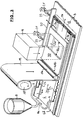
- FIG 3 shows an enlarged perspective view Scale the essential elements from Figures 1 and 2 with the supply of Resin in the form of the resin traces 23 through the nozzles 9 on the already folded Edges 6a and 6b of the wider fiber strip 6 before application of the narrower fiber strip 19.
- This application takes place via a deflecting roller 19a.
- the waveform of the resin tracks 23 indicates one iridescent movement of the nozzles 9 in the direction of the double arrow 9a.
- the supply roll 5 is omitted, as are the two slide rails 15 and the front of the slide rails 20.
- the tray 3 is simplified as a work table shown.
- the load on the edges 6a and 6b is clearly visible in the overlap areas 7a and 7b by the "floating" pressure plate 40 with the window 40a for the passage of the UV radiation of the Hardening radiator 11 and with the upwardly curved leading edge 40b.
- the resulting intermediate product, the inner layer 12, is shown in FIG. 5 shown in section, but supplemented there by the inner tube 2, the was omitted in Figure 3 and is not required for any purpose is.
- FIG. 4 shows the perspective view similar to FIG. 3 essential elements from Figures 1 and 2 with supply of resin on the unspecified edges of the flat, narrow fiber strip 19 before folding the edges 6a and 6b of the wider one Fibrous strip 6.
- the representation is extended to the left and also the inlet area of the tray 3 in connection with the supply roll 5 and another deflecting roller 5a shown.
- Edges of the narrower fiber strip 19 are shown so to speak the edges 6a and 6b in the direction of arrows 6c and 6d continuously folded down on the resin tracks 23.
- the process of Folding around takes place in Figure 3 on the left outside of the drawing.
- the resulting intermediate product, the inner layer 12, is shown in FIG. 6 shown in section, but supplemented there by the inner tube 2, the was omitted in Figure 4 and is not required for any purpose is.
- Figures 7 and 8 show how the intermediates after 5 and 6 in an enveloping device 37 with an outer film 25 can be encased.
- the respective network 13 is - either from a previous device or from an intermediate storage roll, not shown - fed from the left.
- a supply roll 26 is first synchronized from below flat foil tape 27 made of an impermeable to the resin and resistant film placed under the composite 13 on a conveyor belt 28.
- the film strip has a width that is greater than the circumference or twice the width of the composite 13, and its edges 27a and 27b are by a folding device or guide rails 29 around the composite 13 folded around and laid flat, with an overlap area 30 forms.
- the guide rails 29 can by hand wheels 31 and Screws 32 against each other and / or in the same direction over the Conveyor belt 28 can be adjusted.
- a sweatband 35c that passes through two heating stations 35b and a weld seam 36 generated (blackened in Figure 9).
- the welding shoe 35d serves as an abutment for the Sweatband 35c and the overlap area 30 of the outer film 25.
- Die Drive parts are housed in a housing 35e.
- Such Welding device is commercially available and is therefore not described further; it is adjustable in height in the direction of the double arrow 38.
- a final bond 13a is completed in this way and will open a pallet 39 stored for removal.
- the inner layer 12 is still "dry", i.e. - With Except for resin traces 23 and 23-2 - not with the curable resin is impregnated and supplied to an impregnation device, not shown here must be, either immediately after, after a Temporary storage or on a construction site can be carried out.
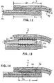
- Figure 10 shows a preliminary end product in the reverse order how the product of Figure 5 has been made.
- the supply roll 18 was advanced to the position 18 'in FIGS. 1 and 4. So it becomes the narrower fiber strip 19 first on the flat Inner hose 2 or the tray 3 is placed, and then the edges 6a and 6b of the wider fiber strip 6 over the edges 19a and 19b of the narrower fiber strip 19 folded over.
- Another inner layer was the composite according to FIG. 6 by 180 Degrees, and then two more strips of fiber were 19-2 and 6-2 in applied in an analogous manner as in Figure 9.
- the intermediate was then again introduced into a device according to FIGS. 7 and 8 and with the outer film 25 surround, creating the "dry" preliminary end product was obtained according to Figure 10.
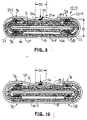
- FIG. 11 shows a section of a shelf 3, which is used as a work table is trained. This is from a supply roll, not shown flat inner tube 2 supplied from a film, but for the Invention is not essential. From another supply roll, not shown becomes a - initially and outside the drawing field Fiber strips 6 fed to the two longitudinal edges 2a and 2b of the Inner tube 2 is folded around. Its width is such that in approximately in the middle an overlap area 7 from the two edges 6a and 6b ( Figure 12) of the fiber strip is formed. Between these two Edges 6a and 6b have a heating element 51 which is connected via a line 60 is supplied with a heating gas. The associated effect is based on of Figures 12 to 14 explained in more detail. The one under the film tube 2 part circumference of the fiber strip 6 is shown in dashed lines, although it is visible through the film tube 2.
- a pressure device 55 which is designed as a rolling body, the can also be cooled if necessary. This will make the fuse link solidified within the overlap area 7 without the Destroy fiber structure.
- the work table is on both sides with parallel slide rails 20, of which only the rear one is shown, and by handwheels 21 and threaded spindles 22 to the hose width can be adjusted.
- Figure 12 shows the overlap area 7 with initially still unconnected Edges 6a and 6b of the fiber strip 6 (line A-A in Figure 11).
- the fiber stiffener 6 consists of two different fiber materials F1 and F2 with different melting temperatures TS1 and TS2.
- F1 and F2 can be a polyester fleece on the one hand and a glass fiber fleece on the other hand, act inseparably by needles or steppes are interconnected. In this case lies - in the overlap area 7 - a polyester fleece on a glass fiber fleece.
- the overlap area 7 passes under during transport Spreading upwards (see FIG. 11, line B-B) on a heating element 51 on that of a double wedge-shaped hollow body with up and down there is gas outlet openings 51b directed at the bottom (see FIG. 16) directed above).
- the length of the radiator 51 still extends Gas outlet gap 51c, which gives the radiator the effect of a flat nozzle gives. It is understood that the gas outlet openings 51b upwards and downward and the gas outlet gap 51c do not coexist must and can be used selectively or alternatively, depending on the direction in which the greater part of the heating energy is directed should.
- the individual gas flows that lead into the depth of the fiber materials are indicated by arrows.
- FIG. 14 shows the overlap area 7 after the two have been combined Edges 6a and 6b beyond the pressure device 55 (of the rolling body) the line C-C in Figure 11.
- the connection point 6g is by a dashed line Rectangle indicated, but this is not necessarily to scale. In In reality, this connection area is very thin or flat and is limited to the surface areas lying directly on top of each other the edges 6a and 6b within the overlap area 7. Die The width "D" of the joint 6g is narrower than the overlap area 7.
- These connection points 6g can also be referred to as “melting traces” will.
- FIG. 15 shows a radiator 50 in double wedge shape, the top 50a roof-shaped and the underside 50b is flat.
- a Holding tube 50c Through a Holding tube 50c are power lines 50d and a measuring line 50e for an im Thermocouple arranged inside the radiator 50, connected to a controller. In this case it is a pure contact heating. At least the leading edge 50f can also be rounded be trained.
- FIG. 16 shows that already discussed in connection with FIG. 11 double wedge-shaped radiator 51 analogous to Figure 15 with flat in one The grid size of the gas outlet openings arranged in its upper side 50a 51b.
- FIG. 17 shows a heating nozzle with a nozzle gap 52a Radiator 52 with exit of the heating gas (arrows) in the transport direction of the Hose.
- FIG. 18 shows a heating nozzle with a nozzle gap 53a Radiator 53 with discharge of the heating gas (arrows) against the transport direction of the hose (arrows).
- the planes of symmetry of the nozzle gaps 52a and 53a can be compared one plane parallel to the contact surface of the edges 6a, 6b be pivotable up or down in the direction of the double arrows "P" to influence the energy distribution. This makes it possible, for example, the fiber strip surface with the greater proportion of polymer fibers to be heated more than the fiber strip surface with the larger proportion of mineral fibers.
- the radiators 51, 52 and 53 also take one due to the gas temperature corresponding surface temperature, so that here in the overlap area 7 the gas heating is accompanied by a contact heating. It has Surprisingly, it was shown that there was no gluing between Radiator and fiber material enters. If necessary, too thermally insulated spacers between at least one of the fiber strips and at least one of the radiator surfaces are provided.
- FIG. 19 explains a further variant of the process control for production a tube made of two differently wide fiber strips 6 and 19 to form two overlap regions 7a and 7b with overhead ones Edges of the narrower fiber strip 19.
- Edges 6a and 6b of the wider fiber strip 6 are initially analogous to FIGS. 1 and 2 folded around the film tube 2, but leave one wide distance "E" between the inward cutting edges 6e, 6f of the wider fiber strip 6.
- the cut edges lying above and exposed 19b and 19c of the narrower fiber strip 19 are directed outwards, so that the two radiators 51 from the outside into the overlap areas 7a and 7b are introduced. In this case, are appropriate the spatial position of the overlap regions 7a and 7b or two radiators 51 these two roller or roller-shaped pressure devices 55 and 56 downstream.
- FIG. 20 explains another variant of the process control for the production a tube made of two differently wide fiber strips 6 and 19 to form two overlap areas 7a and 7b with underlying ones Edges of the narrower fiber strip 19.
- the narrower fiber strip 19 is placed on the film tube 2 and the wider fiber strip 6 is subsequently wrapped around the film tube 2 and the narrower fiber strip 19 folded around, but leaves here likewise a wide distance "E" between those facing inwards Cut edges 6e and 6f of the wider fiber strip 6.
- the top and free lying cut edges 6e and 6f of the wider fiber strip 6 are after directed inside so that the two radiators 51 from the inside in the overlap regions 7a and 7b are introduced. This creates the advantage that the two radiators 51 via a central supply line 61st can be supplied with hot air. Otherwise nothing changes Principles of the procedure.
- the adjustability of the slide rails 15 and 20 is not only used for adaptation to different widths of the flat-lying hose, but also for its transverse displacement with respect to the supply rolls 5, 18 and 18 '.
- the supply rolls 5 can also be used for transverse displacement and 18 or 18 'individually, together or in opposite directions in the transverse direction can be arranged displaceably relative to the shelf 3 or it can Supply rolls with even wider or narrower fiber strips are used will. In this case, you can build a multi-layer inner layer 12 also more fiber strips are fed without that after Manufacturing the first composite 13 would require a turn.
- FIG. 21 shows one such application: the fiber strips 6 and 19 were analogous to the method either on a device according to the Figures 1 and 2 or processed according to Figure 20, the intermediate product has led to Figure 5, but with the difference that in two parallel overlap areas 7a and 7b each Connection points (resin or melt traces) 62 were created.
- Such a composite can then without turning instead of the inner tube 2 introduced into a device analogous to Figures 7, 8 or 11 will. Only the fiber strip 6 is then through a fiber strip 6-3 to replace, the width of which is more than twice the width of the lay flat composite, so that a single wide overlap area 7 is formed, which is also held together by two connecting points 63 becomes.
- the device and material guide then look something like that left halves of Figures 7 and 8. Only in the place of the film and the Welding device 35 then again enter the fiber strips 6-3, a storage container 8 with two resin nozzles 9 and a curing lamp 11, which in in this case are arranged above the central overlap region 7.
- connection technology according to FIGS. 11 to 20 can be used will. It can be clearly seen that the overlap areas 7, 7a and 7b with the connection points (traces of resin or melt) 62 and 63 are staggered on the circumference, so that none Thickness accumulations occur.
- the intermediate product according to FIG. 21, again a composite, can then be one of those already described Methods are further processed, for example in devices according to Figures 7 and 8. In this, the tubular film 25 with an overlap area 30 and two welds 64 applied.
- FIG. 22 now shows a cross section through an egg-shaped sewer with a renovation hose 65, which is very flat when lying flat largely corresponds to Figure 21.
- a fold line 66 of the cross section is dash-dotted lines, and care must be taken that on this fold line no joints (traces of resin or melt) and if possible there are also no overlap regions 7, 7a, 7b, 30.
Abstract
Description
Die Erfindung betrifft ein Verfahren zum Herstellen eines Schlauchs für die Auskleidung von Rohrleitungen und Kanalsystemen mit mindestens einer aus einem Faserwerkstoff bestehenden, mit einem aushärtbaren Harz imprägnierbaren Innenlage, deren Ränder durch Aufeinanderlegen auf einen gleichen oder einen anderen Faserstreifen auf dem Umfang des Schlauchs mit mindestens einem in Längsrichtung verlaufenden fest verbundenen Überlappungsbereich versehen werden und die anschließend mit einer gegenüber dem Harz undurchlässigen Außenfolie umgeben wird. The invention relates to a method for producing a hose for the Lining of pipelines and sewer systems with at least one made of a fiber material, impregnable with a hardenable resin Inner layer, the edges of which lay on top of one another same or a different fiber strip on the circumference of the hose with at least one permanently connected in the longitudinal direction Overlap area and then with a outer film is impermeable to the resin.
Derartige Schläuche werden auch als "Liner" bezeichnet. Sowohl ihre Herstellung als auch ihre Verlegung bei der Sanierung von Rohrleitungen und Kanalsystemen sind kompliziert und zeitaufwendig, und zwar insbesondere dann, wenn es sich um die Herstellung und Verarbeitung von Schläuchen größerer Länge handelt. Das tragende Element ist nach der Aushärtung die schlauchförmig geschlossene Lage aus dem imprägnierten Faserwerkstoff. Zur Erzielung einer hohen Festigkeit muß das Harz bzw. der Faserwerkstoff soweit wie irgend möglich frei von Hohlräumen sein, die durch Lufteinschlüsse aber auch durch ungenügende Tränkung des Faserwerkstoffs entstehen können. Die Aushärtung des Harzes kann entweder durch Wärme, sichtbares Licht oder ultraviolettes Licht erfolgen. Für diesen Zweck ist eine ganz Reihe von Harzmaterialien im Handel, die zur Beschleunigung der Aushärtung mit Aktivatoren und Beschleunigern versetzt sein können. Bekannt sind auch kalt aushärtbare Harze, bei denen die Aushärtung verzögert eingestellt wird, bei denen sich aber während des Härteprozesses eine Temperaturerhöhung einstellt.Such hoses are also referred to as "liners". Both their manufacture as well as their laying when renovating pipelines and Channel systems are complicated and time consuming, especially then when it comes to the manufacture and processing of hoses longer length. The load-bearing element is the after curing tubular closed layer made of the impregnated fiber material. To achieve high strength, the resin or fiber material must be as far as possible free of voids caused by air pockets but also arise from insufficient impregnation of the fiber material can. The resin can be cured either by heat, visible light or ultraviolet light. For this purpose there is one quite a number of resin materials in the trade, which accelerate curing can be mixed with activators and accelerators. Known are also cold-curable resins in which curing is delayed which, however, develop during the hardening process Temperature increase.
Derartige Schläuche oder Liner können beispielsweise in flachliegendem Zustand in den Sanierungsbereich eingezogen und nach Anbringung von sogenannten Endverschlüssen durch ein unter Druck stehendes Medium aufgebläht und gegen die zu sanierenden Wandungen gepreßt werden. Eine andere Methode des Einbringens des Schlauches oder Liners besteht im sogenannten Umstülpen oder Evertieren. In beiden Fällen ist der imprägnierte Faserwerkstoff zum Zwecke der Handhabung des Schlauchs auf der Außenseite von einer gasundurchlässigen Außenlage aus einer schlauchförmigen Folie umgeben, die selbstverständlich auch harzdicht ist. Beim Aufblasen eines solchen Schlauchs kommt nun diese Außenfolie mit der zu sanierenden Wandfläche in Berührung, und der imprägnierte Faserwerkstoff liegt innen. Um nun Strahlungsquellen für die Aushärtung durch einen solchen aufgeblasenen Schlauch hindurch bewegen zu können, wird in diesen Schlauch auf der Baustelle eine schlauchförmige Innenfolie eingezogen. Beim Umstülpen oder Evertieren ist diese Maßnahme überflüssig, da durch den Umstülpvorgang der ursprünglich innenliegende imprägnierte Faserwerkstoff nach außen gelangt, jedoch ist der Vorgang des Umstülpens und des nachträglichen Transports der Strahlungsquellen durch den umgestülpten Schlauch keine einfach zu bewerkstelligende Maßnahme.Such hoses or liners can, for example, in a flat Condition moved into the redevelopment area and after the installation of so-called End caps inflated by a medium under pressure and pressed against the walls to be renovated. A another method of inserting the hose or liner is the so-called Invert or Evert. In both cases it is impregnated Fiber material for the purpose of handling the hose on the outside from a gas-impermeable outer layer from a tubular Surround foil, which is of course also resin-tight. When inflating Such a tube now comes with this outer film renovating wall surface in contact, and the impregnated fiber material is inside. To now radiation sources for curing by a to be able to move such an inflated hose through this hose a tubular inner film is pulled in at the construction site. This measure is superfluous when inverting or inverting, because by the everting process, the originally impregnated inside Fiber material reaches the outside, however, is the process of turning it inside out and the subsequent transport of the radiation sources by the inverted Hose is not an easy task.
Besonders schwierig ist hierbei die Durchführung einer gleichmäßigen Imprägnierung, und zwar insbesondere dann, wenn mindestens eine der Oberflächen des Faserwerkstoffs mit einer Folie versehen ist. Man ist daher in der Regel so verfahren, daß man den Schlauch oder Liner erst auf der Baustelle fertig konfektioniert hat, indem man die Tränkung oder Imprägnierung auf der Baustelle durchgeführt hat. Beim Umstülpen oder Evertieren hat man sogar Verfahren angewandt, den Faserwerkstoff erst an der Stelle des Umstülpens mit dem jeweiligen Harz zu tränken. Diese Maßnahme erfordert die Bereitstellung von entsprechenden Vorrichtungen und deren Betrieb auf der Baustelle, so daß eine ständige Verlegung der Vorrichtungen erforderlich ist.It is particularly difficult to carry out a uniform impregnation, in particular if at least one of the surfaces of the fiber material is provided with a film. One is therefore in the As a rule, proceed in such a way that the hose or liner is only on site ready-made by impregnation or impregnation the construction site has carried out. When inverting or inverting you have even applied processes, the fiber material only at the point of the everting to soak with the respective resin. This measure requires the Provision of appropriate devices and their operation on the Construction site, so that a constant relocation of the devices is required.
Durch die DE 22 40 153 C2 und die US 4 009 063 ist es bekannt, bei der Herstellung eines Sanierungsschlauchs für Rohrleitungen und Kanalsysteme einen imprägnierfähigen Faserstreifen vor dem Imprägnieren mit einem aushärtbaren Harz um einen Innenschlauch aus Folie herumzufalten und den sich dabei ausbildenden Überlappungsbereich durch Nähen, Kleben oder Schweißen zu verbinden. Beim Nähen oder Schweißen entstehen jedoch eingefallene Stellen, die wie eine Steppnaht in einem wattierten Stoff aussehen und die Festigkeit des ausgehärteten Schlauchs beeinträchtigen. Dies ist insbesondere dann der Fall, wenn nur ein einziger Faserstreifen eingesetzt wird, weil dann keine statistische Verteilung von Schwachstellen eintritt. Über die Art des Klebers oder des Klebevorgangs werden keine Aussagen gemacht. Breitflächige Verklebungen behindern jedoch den Imprägniervorgang und das vor dem Imprägnieren erforderliche Evakuieren, außerdem dringen die meisten Klebstoffe nicht genügend tief in den Faserstreifen ein, so daß die Gefahr besteht, daß Oberflächenteile des Faserstreifens beim Auftreten einer Zugspannung mit dem Klebstoff herausgerissen werden. Die meisten Kleber enthalten Lösungsmittel und/oder Weichmacher, die in dem endgültig eingebrachten Imprägnierharz durch Blasenbildung Hohlräume und damit Schwachstellen erzeugen. Schließlich werden zahlreiche Kleber von den später eingebrachten Imprägnierharzen angelöst oder aufgeweicht, und sie verbinden sich auch nicht mit den Imprägnierharzen.From DE 22 40 153 C2 and US 4 009 063 it is known in the Manufacture of a rehabilitation hose for pipelines and sewer systems an impregnable fiber strip before impregnation with a curable Resin to fold around an inner tube of foil and the forming overlap area by sewing, gluing or To join welding. When sewing or welding, however, arise sunken spots that look like quilting in a padded fabric and impair the strength of the hardened hose. This is particularly the case when there is only a single fiber strip is used because then no statistical distribution of vulnerabilities entry. Nothing is said about the type of adhesive or the gluing process Statements made. However, wide-area gluing impairs the impregnation process and the evacuation required before impregnation, moreover, most adhesives do not penetrate deep enough into the fiber strips a so that there is a risk that surface parts of the fiber strip ripped out with adhesive if tension occurs will. Most adhesives contain solvents and / or Plasticizers that are in the final impregnation resin Blistering creates voids and thus weak spots. Finally numerous adhesives from the later introduced impregnation resins dissolved or softened, and they also do not combine with the impregnation resins.
Durch die EP 0 275 060 A1 ist es zu dem gleichen Zweck bekannt, einen
Faserstreifen mit einer bereits aufgebrachten Außenfolie um einen Innenschlauch
herumzulegen und dabei die Kanten des Faserstreifens stumpf
aufeinander stoßen zu lassen und zu vernähen. Um die Naht, die auch durch
die Außenfolie hindurchgeht, abzudichten und zu verstärken, wird
nachfolgend ein Nahtstreifen aufgeklebt. Hierbei ist es jedoch nicht möglich,
weitere Faserstreifen aufzubringen, weil die Außenfolie die gleichzeitige
Evakuierung und die Imprägnierung aller Faserstreifen verhindern würde.
Der bekannte Schlauch wird durch einen sogenannten Evertiervorgang in die
zu sanierende Rohrleitung eingebracht und erst hierbei imprägniert, derart,
daß der Faserstreifen nach außen und die Außenfolie nach innen gelangt.
Der Zweck ist die Verbindung des imprägnierten Faserstreifens mit der
Rohrleitung.From
Durch die W0 91/18234 ist ein ähnliches Verfahren bekannt, bei dem die überlappungsfreie Naht durch einen thermischen Stumpfschweißvorgang des bereits mit einer Innenfolie versehenen Faserstreifens durchgeführt wird. Danach wird der Verbund aus Innenfolie und Faserstreifen durch zwei Harzbäder geführt und darin imprägniert und nachfolgend mit einer Außenfolie versehen, die verschweißt wird. Eine solche Stumpfschweißnaht bildet jedoch eine ausgesprochene Schwachstelle, so daß auf die Naht auch in diesem Falle eine Nahtverstärkungsstreifen aufgeflämmt werden muß. Dieses Verfahren setzt eine sehr komplizierte Imprägnierungsanlage voraus. A similar process is known from WO 91/18234, in which the Overlap-free seam through a thermal butt welding process of the fiber strip already provided with an inner film is carried out. Then the composite of inner film and fiber strips is divided by two Resin baths led and impregnated therein and then with an outer film provided, which is welded. Such a butt weld forms however, a pronounced weak point, so that the seam also in in this case, a seam reinforcement strip must be flamed. This process requires a very complicated impregnation plant.
In den vorstehend genannten Fällen ist die radiale Dehnfähigkeit des Schlauchs eng begrenzt, insbesondere deswegen, weil der Nahtverstärkungsstreifen selbst an der Dehnung nicht teilnimmt und zum Ablösen neigt. Man hat daher solche Nahtverstärkungsstreifen auf den bereits imprägnierten Schlauch zusätzlich aufgesteppt, wodurch Löcher und Lecks im Schlauchverbund entstehen.In the above cases, the radial extensibility of the Hose narrowly limited, especially because of the seam reinforcement strip itself does not participate in the stretch and to peel off tends. One has therefore such seam reinforcement strips on the already impregnated Hose additionally stitched, causing holes and leaks in the Hose assembly arise.
Durch die EP 0 510 306 A1, die DE 41 30 459 A1, die DE 44 27 633 C2 und
die DE 44 45 166 A2 ist es bekannt, Überlappungsbereiche von einem oder
mehreren Faserstreifen nicht miteinander zu verbinden, so daß Sanierungsschläuche
von besonders guter Dehnfähigkeit erhalten werden. Dies
hat jedoch den Nachteil, daß die Überlappungsbereiche relativ breit gehalten
werden müssen, um bei der Aufweitung die Überlappung nicht zu verlieren.
Da die Dehnung bei der Verlegung durch Druckluft erfolgt, behindern die
Nachbarstreifen eine Verschiebung in den breiten Überlappungsbereichen.
Andererseits können sich die Ränder der Faserstreifen bei der
Weiterverarbeitung und/oder beim Transport verschieben, umklappen oder
Falten bilden.Through
In allen vorstehend genannten Fällen wird die Herstellung von Sanierungsschläuchen beschrieben, die fertig imprägniert sind und sehr spezielle Imprägnierungsverfahren und entweder komplizierte Nachbehandlungen voraussetzen oder bei der Weiterverarbeitung und beim Transport durch ihren labilen Aufbau die beschriebenen Probleme verursachen.In all of the above cases, the manufacture of rehabilitation hoses described, which are fully impregnated and very special impregnation processes and either require complicated post-treatments or in further processing and transport by your unstable structure cause the problems described.
Der Erfindung liegt daher die Aufgabe zugrunde, ein Verfahren der eingangs genannten Gattung anzugeben, das zu einem stabilen und dehnfähigen Vorprodukt für eine endgültige Imprägnierung führt und einfach auszuführen ist.The invention is therefore based on the object of a method of the beginning Specify the type mentioned, which leads to a stable and flexible Pre-product leads to a final impregnation and easy to carry out is.
Die Lösung der gestellten Aufgabe erfolgt bei dem eingangs angegebenen
Verfahren erfindungsgemäß dadurch, daß
Die Erfindung enthält also - zur Lösung der gleichen Aufgabe - zwei alternative Lösungsgedanken, die auf dem selben mechanischen Prinzip beruhen und beide im Durchlaufverfahren bzw. auch in kinematischer Bewegungsumkehrung durchführbar sind und die zu einer ausreichenden Festigkeit der Verbindung gegenüber Scherspannungen führen.The invention thus contains two alternatives to achieve the same object Solution ideas based on the same mechanical principle and both in a continuous process or in a kinematic reversal of motion are feasible and the sufficient strength of the Connect against shear stresses.
Bei der Lösung mit dem Merkmal b1) wird zwischen die zu den Oberflächen der Faserstreifen parallelen Berührungsflächen eine kontinuierliche, unterbrochene, changierende oder mäandrierende, vorzugsweise schmale, Harzspur eingebracht, die genügend tief in die Faserstreifen eindringt, ohne dessen Faserstruktur in unmittelbarer Umgebung der Harzspur zu zerstören oder Einfallstellen zu erzeugen, und die bei der abschließenden Imprägnierung mit dem Imprägnierharz verträglich bzw. kompatibel ist und die Mikroströmungen bei der Imprägnierung nicht behindert. In the case of the solution with feature b1), the surface becomes between the fiber strips parallel contact surfaces a continuous, interrupted, iridescent or meandering, preferably narrow, trace of resin introduced, which penetrates sufficiently deep into the fiber strips without to destroy its fiber structure in the immediate vicinity of the Harzspur or sink marks, and the final impregnation is compatible or compatible with the impregnating resin and the micro currents not hindered in the impregnation.
Bei der Lösung mit dem Merkmal b2) wird mindestens eine der Berührungsflächen der Faserstreifen oberflächlich angeschmolzen, und zwar genügend. tief, und unter Druckanwendung mit der jeweils anderen Oberfläche verschmolzen, gleichfalls ohne die Faserstruktur in unmittelbarer Umgebung des Schmelzbereichs vollständig zu zerstören. Hierbei kann auf den Zusatz von Fremdstoffen vollständig verzichtet werden, so daß sich die Frage einer Kompatibilität gar nicht erst stellt.In the solution with feature b2), at least one of the contact surfaces the fiber strip melted on the surface, enough. deep, and fused to the other surface under pressure, likewise without the fiber structure in the immediate vicinity completely destroy the melting range. You can click on the addition of foreign substances are completely dispensed with, so that the question of a Compatibility doesn't even exist.
Das Merkmal b2) beruht auf der Überlegung, daß die höherschmelzenden Fasern ihre Struktur und die Zwischenräume behalten, das Fasermaterial also nicht "einfällt" oder "einsinkt". Andererseits werden die niedrigschmelzenden Fasern weich bzw. klebrig und verbinden sich mit den höherschmelzenden Fasern. Es hat sich überraschend gezeigt, daß die Verbindung durch größere Körperkräfte senkrecht zu den Berührungsflächen unter Herausreißen einzelner Fasern getrennt werden kann, daß aber die Verbindung gegenüber tangentialen Kräften durchaus fest genug ist, um die Weiterverarbeitung zu überleben. Dadurch, daß die Erwärmung von der Berührungsfläche aus erfolgt, also von innen heraus, stellt sich nach beiden Seiten ein fallender Temperaturgradient ein, bei dem der allergrößte Teil der Faserstruktur auch der niedrigschmelzenden Fasern erhalten bleibt.The feature b2) is based on the consideration that the higher melting Fibers keep their structure and the gaps, the fiber material So it doesn't "come in" or "sink". On the other hand, the low-melting ones Fibers soft or sticky and combine with the higher melting ones Fibers. It has surprisingly been found that the connection due to larger physical forces perpendicular to the contact surfaces can be separated by tearing out individual fibers, but that the Connection against tangential forces is quite strong enough to Survive finishing. Because the heating from the contact surface from, that is, from within, turns to both A falling temperature gradient at which the vast majority of the The fiber structure of the low-melting fibers is preserved.
Damit bleiben sowohl die Evakuierungs- und Imprägnierfähigkeit als auch die Transparenz für die Härtungsstrahlung - auch im Nahtbereich - erhalten. Die Erfindung beruht auf der gemeinsamen Berücksichtigung des Schmelzverhaltens der niedrigschmelzenden Fasern, ihrer Verklebung mit den höher schmelzenden Fasern ohne wesentlichen Verlust an Porigkeit, so daß also kein störendes "Einfallen" der Faserstreifen an der Verbindungsstelle erfolgt. Es kann angenommen werden, daß die höherschmelzenden Fasern hierbei eine Stützfunktion für die niedrigschmelzenden Fasern ausüben. This leaves both the evacuation and impregnation ability as well Preserve transparency for the curing radiation - also in the seam area. The The invention is based on the joint consideration of the melting behavior the low-melting fibers, their gluing with the higher melting fibers with no substantial loss of porosity, so that there is no disruptive "falling in" of the fiber strips at the connection point. It can be assumed that the higher melting fibers here have a supporting function for the low-melting fibers.
Mittels der Erfindung lassen sich Vorprodukte für die Endimprägnierung erzeugen, die in radialer Richtung dehnbar sind, unerwünschte Verschiebungen, ein Umschlagen von Rändern und/oder Faltenbildungen der Faserstreifen beim Transport und bei der Weiterverarbeitung verhindern und zu keinen Porositäten, Kapillaren (Dampfdurchtritt) und Querschnittsschwächungen durch Nähte oder Schweißungen führen (sogenannter Steppnaht- oder Wattierungseffekt). Dadurch ist die Anzahl der Faserstreifen - in Umfangsrichtung und in der Dicke gesehen - nicht begrenzt. Es wird jedoch betont, daß die Erfindung auch darin besteht und sich bereits dann vorteilhaft auswirkt, wenn auf einem Schlauchumfang von 360 Grad nur eine Überlappungsstelle vorgesehen ist und wenn nur eine Innenlage vorhanden ist.By means of the invention, preliminary products for the final impregnation can be produced, which are stretchable in the radial direction, undesirable displacements, folding of edges and / or wrinkling of the Prevent fiber strips during transport and further processing and no porosity, capillaries (steam penetration) and cross-sectional weakening through seams or welds (so-called Topstitching or padding effect). This is the number of fiber strips - Seen in the circumferential direction and in the thickness - not limited. It will however emphasizes that the invention also consists in and then has an advantageous effect if only one on a hose circumference of 360 degrees Overlap point is provided and if there is only one inner layer is.
Auch wird das Harz der ausgehärteten Harzstreifen nicht angelöst oder aufgeweicht, wie z.B. ein Kleber, der ein Fremdstoff ist, sondern geht vielmehr mit dem Harz der Endimprägnierung einen untrennbaren Verbund ein. Schließlich behindern die Harzstreifen auch nicht den Harzfluß oder die Evakuierung bei der Endimprägnierung. Es handelt sich um einen irreversiblen Vorgang, der nicht wieder aufgehoben werden kann.The resin of the hardened resin strips is not dissolved or softened, such as. an adhesive that is a foreign substance, but rather goes an inseparable bond with the resin of the final impregnation. Finally, the resin strips do not hinder the resin flow or the Evacuation during the final impregnation. It is an irreversible one Process that cannot be canceled.
Durch die Elastizität der Innenlage vor dem Aushärten der Endimprägnierung wird nicht nur eine Anpassung bzw. ein Anschmiegen des Schlauchs an Unregelmäßigkeiten der zu sanierenden Rohrleitung unter der Wirkung eines Druckmediums ermöglicht, sondern es entsteht auch eine Vorspannung, die im Harz "eingefroren" wird und ähnlich wie bei Spannbeton zu einer Steigerung der Festigkeit und Druckdichtigkeit, sowie zu einer statischen Berechenbarkeit des ausgehärteten Schlauchs führt. Als Druckmedien können heiße Gase und Wasserdampf sowie entsprechend temperiertes Wasser verwendet werden.Due to the elasticity of the inner layer before the final impregnation hardens will not only be an adjustment or snug fitting of the hose irregularities in the pipeline to be renovated under the effect of a printing medium, but it also creates one Preload that is "frozen" in the resin and similar to Prestressed concrete to increase strength and pressure tightness, as well leads to a static predictability of the hardened hose. As Print media can contain hot gases and water vapor as well tempered water can be used.
Es entstehen keine Trennungen der Überlappungsbereiche durch ungewollte
Querverschiebungen der Faserstreifen zueinander und/oder Ausdehnungen
und damit keine Schwachstellen, sondern vielmehr in gewisser Weise
"nahtlose" Innenlagen 12, und zwar selbst dann, wenn die Überlappungsbereiche
schmal gehalten werden, was die radiale Dehnfähigkeit
begünstigt, da Verschiebungen von mehreren Innenlagen gegeneinander
beim Dehnen nicht erforderlich sind. Diese Querverschiebungen treten beim
Stand der Technik bekanntlich dadurch auf, daß die unverbundenen Folienstreifen
selbst wenig dehnfähig sind und die Überlappungsbereiche auf dem
Umfang versetzt angeordnet sein müssen, um Dickenanhäufungen zu vermeiden.There are no separations of the overlap areas due to unwanted ones
Cross-shifts of the fiber strips to each other and / or extensions
and therefore not weak points, but rather in a way
"Seamless"
Es ist dabei besonders vorteilhaft, wenn als aushärtbares Hart für die Verbindung der Ränder der Innenlage das gleiche Harz verwendet wird, wie für die Imprägnierung des Restquerschnitts der Innenlage.It is particularly advantageous if as a hardenable hard for the connection the edges of the inner layer the same resin is used as for the impregnation of the remaining cross-section of the inner layer.
Ein weiterer Vorteil entsteht dann, wenn die Verbindungsstelle(n) in Umfangsrichtung des Schlauchs schmal ist/sind im Verhältnis zur Breite des jeweiligen Überlappungsbereichs.Another advantage arises when the connection point (s) in the circumferential direction of the hose is / are narrow in relation to the width of the respective Overlap area.
Bei relativ breiten Überlappungsbereichen ist es auch möglich und vorteilhaft, in mindestens einem, bzw. dem breitesten Überlappungsbereich mehr als eine Verbindungsstelle zu erzeugen.With relatively wide overlap areas, it is also possible and advantageous to in at least one or the widest overlap area more as a liaison.
Ein solcher Schlauch kann in besonders vorteilhafter Weise von Anfang an mit einem Innenschlauch versehen werden, dies geschieht in der Weise, daß die mindestens eine, aus Faserwerkstoff bestehende Innenlage um einen gegenüber dem Harz undurchlässigen Innenschlauch herumgelegt wird und daß das Harz des mindestens einen Überlappungsbereichs nach dem Aufbringen durch Energiestrahlung ausgehärtet wird.Such a hose can be particularly advantageous from the start be provided with an inner tube, this is done in such a way that the at least one inner layer made of fiber material by one is placed around the inner tube impermeable to the resin and that the resin of the at least one overlap area after the Application is cured by energy radiation.
In diesem Falle ist der Innenschlauch eine vorteilhafte Fertigungshilfe für die Innenlage aus dem Fasermaterial bzw. aus den Faserstreifen, und es ist nicht mehr erforderlich, nachträglich noch einen Innenschlauch einzuziehen. In this case, the inner tube is an advantageous manufacturing aid for the Inner layer from the fiber material or from the fiber strips, and it is no longer necessary to pull an inner hose later.
Die Herstellung kann mit einer beliebigen Anzahl von Überlappungsbereichen auf dem Umfang der Innenlage erfolgen, nämlich dadurch, daß die. Innenlage mit an mindestens einer Überlappungsstelle aufeinanderliegenden Wandungsteilen über einen Kalibrierkörper geführt wird, und daß nach Einbringung des aushärtbaren Harzes an jeder der Überlappungsstellen dessen Aushärtung durchgeführt wird.Manufacturing can be done with any number of overlap areas take place on the circumference of the inner layer, namely in that the. Inner layer with one another lying on at least one overlap point Wall parts is guided over a calibration body, and that after insertion the curable resin at each of the overlap points thereof Curing is carried out.
Will man das Verfahren in der Horizontalen durchführen, so wird in besonders
zweckmäßiger Weise so verfahren, daß die mindestens eine, aus
Faserwerkstoff bestehende Innenlage aus zwei Faserstreifen gebildet wird,
von denen der eine breiter ist als der halbe Umfang des Innenschlauchs und
der andere maximal die gleiche Breite hat wie der halbe Umfang des Innenschlauchs,
daß zunächst der breitere Faserstreifen, auf eine Ablage gefördert
und mit seinen beiden Rändern einwärts gefaltet wird, daß der
schmälere Faserstreifen entweder vor oder nach der Faltung des breiteren
Faserstreifens unter Herstellung zweier Überlappungsbereiche der beiden
Ränder auf der gleichen Ablage abgelegt wird, wobei in die beiden Überlappungsbereiche
das aushärtbare Harz eingebracht wird, wobei entweder
Die Ablage kann dabei aus einem einfachen Arbeitstisch, in vorteilhafter Weise aus einem Förderband bestehen. Das Ablegen erfolgt dabei auch mittelbar, beispielsweise dann, wenn sich auf der Ablage ein Innenschlauch befindet.The shelf can be from a simple work table, in an advantageous manner Way consist of a conveyor belt. The filing is also done indirectly, for example when there is an inner tube on the shelf located.
Diese Fertigungsweise hat den großen Vorteil, daß der Faltvorgang immer nur auf der Oberseite der Ablage stattfindet. Es ist also nicht erforderlich - wie beim Stande der Technik - Faserstreifen abwechselnd von unten nach oben und dann von oben nach unten um den zuvor gebildeten Schlauchverbund herumzufalten. Dabei entstehen nämlich besondere Probleme beim Faltvorgang auf der Unterseite. Der Stand der Technik befaßt sich auch nur mit dem Herumfalten ohne eine Verbindung der einzelnen Faserstreifen.This manufacturing method has the great advantage that the folding process always only takes place on top of the shelf. So it's not necessary - as in the prior art - fiber strips alternately from below above and then from top to bottom around the previously formed hose assembly fold around. This creates special problems with the Folding process on the bottom. The state of the art only deals with folding around without connecting the individual fiber strips.
Eine weitere Ausgestaltung der Erfindung ermöglicht auch den Aufbau der Innenlage aus mehr als einer Innenlage aus Fasermaterial, und zwar dadurch, daß nacheinander mindestens zwei aus Faserwerkstoff bestehende Innenlagen auf der Ablage erzeugt werden und daß die erste Innenlage vor dem Aufbringen der zweiten und jeder weiteren Innenlage um 180 Grad gewendet wird.A further embodiment of the invention also enables the construction of the Inner layer made of more than one inner layer made of fiber material, namely by that successively at least two consisting of fiber material Inner layers are generated on the shelf and that the first inner layer before the application of the second and each further inner layer by 180 degrees is turned.
Um hierbei Dickenanhäufungen durch die mehrfach entstehenden Überlappungsbereiche zu vermeiden, ist es besonders vorteilhaft, wenn beim Aufbau eines Schlauchs aus mehr als zwei Innenlagen aus Faserwerkstoff die Lagen der Überlappungsbereiche durch relative Querverschiebung von Faserstreifen auf den Umfang des Schlauchs verteilt werden.In order to do this, accumulations of thickness due to the multiple overlapping areas To avoid, it is particularly advantageous if the Construction of a hose from more than two inner layers made of fiber material the positions of the overlapping areas by relative transverse displacement of Fiber strips are distributed over the circumference of the hose.
Beim Aufbringen der Außenfolie, die gegenüber dem ganz zum Schluß einzubringenden Imprägnierungsharz beständig und gegenüber diesem dicht sein muß, wird in besonders vorteilhafter Weise so verfahren, daß eine Außenfolie mit einer Breite verwendet wird, die größer ist als der Umfang der letzten, aus Fasermaterial bestehenden Innenlage, und daß die Außenfolie, von unten kommend, unter Bildung eines Überlappungsbereichs um die mindestens eine Innenlage herumgefaltet und im Überlappungsbereich verschweißt wird. When applying the outer film, the one to be brought in at the very end Impregnation resin resistant and impervious to it must be, is proceeded in a particularly advantageous manner that a Outer film is used with a width that is larger than the circumference of the last inner layer made of fiber material, and that the outer film, coming from below, forming an overlap area around the folded at least one inner layer and welded in the overlap area becomes.
Bei einem Verfahren, bei dem der Faserwerkstoff mindestens einer der
Ränder im Überlappungsbereich oberflächlich angeschmolzen wird, worauf
die Ränder unter Druckanwendung miteinander verschmolzen werden, wird
in vorteilhafter Weise so vorgegangen, daß
Dies geschieht in besonders vorteilhafter Weise dadurch, daß zwischen die Ränder der Faserstreifen ein Heizgas mit einer Temperatur eingeblasen wird, die zwischen den Schmelztemperaturen der beiden Faserstreifen liegt, insbesondere dadurch, daß die Temperatur des Heizgases so gewählt wird, daß der Faserwerkstoff mit der niedrigeren Schmelztemperatur von seiner Oberfläche her örtlich begrenzt aufschmilzt und sich mit dem nicht aufschmelzenden Faserwerkstoff mit der höheren Schmelztemperatur verbindet.This is done in a particularly advantageous manner in that between the A hot gas is blown in at the edges of the fiber strips at a temperature which lies between the melting temperatures of the two fiber strips, in particular by choosing the temperature of the heating gas that the fiber material with the lower melting temperature of its Surface melts locally and with the non-melting Fiber material combines with the higher melting temperature.
Die Erfindung betrifft auch einen nach dem vorstehend beschriebenen Verfahren
und seinen Varianten hergestellten Schlauch, wobei die wesentlichen
Merkmale dieses Schlauchs in den Ansprüchen 20 bis 26 beschrieben sind.The invention also relates to one according to the method described above
and its variants manufactured hose, the essential
Features of this hose are described in
Die Erfindung betrifft auch eine Vorrichtung zum Herstellen eines Schlauchs mit mindestens einer aus mindestens einem imprägnierfähigen Faserstreifen bestehenden Innenlage für die Auskleidung von Rohrleitungen und Kanalsystemen, mit einer zumindest im wesentlichen waagrechten Ablage und einer Transporteinrichtung für den Transport des Schlauchs, mit mindestens einer Vorratsrolle mit je einem imprägnierfähigen Faserstreifen, der der Ablage zuführbar ist, und mit Einrichtungen zum Herumfalten der Streifenränder.The invention also relates to a device for producing a hose with at least one of at least one impregnable fiber strip existing inner layer for the lining of pipelines and sewer systems, with an at least substantially horizontal shelf and a transport device for the transport of the hose, with at least a supply roll, each with an impregnable fiber strip, the storage is feedable, and with means for folding around the strip edges.
Zur Lösung der gleichen Aufgabe ist eine solche Vorrichtung gekennzeichnet
durch:
oder durch
sowie durch
or by
as well as through
Mit einer solchen Vorrichtung kann im unteren Grenzfall jede Innenlage aus
einem einzigen Faserstreifen hergestellt werden. Für die Herstellung einer
jeden Innenlage aus zwei Faserstreifen ist jedoch eine Vorrichtung besonders
gut geeignet, die folgende Merkmale aufweist:
Im Zuge einer wiederum weiteren Ausgestaltungen der Erfindung wird mit besonderem Vorteil eine Konstruktionsvorschrift angewandt, bei der die Transporteinrichtung aus einem Förderband besteht und bei der das Führungssystem für die Faltung der Ränder des Faserstreifens aus spiegelbildlich über dem Förderband angeordneten ersten Gleitschienen besteht, die unabhängig voneinander quer zur Laufrichtung des Förderbandes verstellbar sind.In the course of yet another refinement of the invention, particular advantage applied a design specification in which the Transport device consists of a conveyor belt and in which the Guide system for folding the edges of the fiber strip First slide rails arranged in mirror image above the conveyor belt exists independently of one another transversely to the running direction of the conveyor belt are adjustable.
Hierdurch kann die Transporteinrichtung nicht nur an die Herstellung unterschiedlich breiter Schläuche angepaßt werden (die Breite bezieht sich auf den flachliegenden Schlauch), sondern die Einstellmöglichkeiten führen auch dazu, daß die Überlappungsbereiche auf dem Umfang versetzt zueinander angeordnet werden können. Die einzelnen Möglichkeiten hierzu werden in der Detailbeschreibung noch näher erläutert.As a result, the transport device can differ not only in terms of manufacture wider hoses (the width refers to the flat-lying hose), but the setting options also lead to the fact that the overlap areas on the circumference offset from each other can be arranged. The individual options for this are described in the detailed description explained in more detail.
Weitere vorteilhafte Ausgestaltungen des Erfindungsgegenstandes ergeben sich aus den übrigen Vorrichtungsansprüchen; ihre besonderen Vorteile sind gleichfalls in der Detailbeschreibung näher erläutert. Further advantageous configurations of the subject matter of the invention result from the other device claims; their particular advantages are also explained in more detail in the detailed description.
Ausführungsbeispiele des Erfindungsgegenstandes, die einzelnen Verfahrensschritte und unterschiedliche Endprodukte werden nachstehend anhand der Figuren 1 bis 22 näher beschrieben, wobei zumindest die einzelnen Verfahrensschritte kontinuierlich betrieben werden.Embodiments of the subject matter of the invention, the individual process steps and different end products are shown below of Figures 1 to 22 described in more detail, at least the individual Process steps are operated continuously.
Es zeigen:
- Figur 1
- ein erstes Ausführungsbeispiel einer ersten Variante eines
ersten Verfahrensschritts für ein Zwischenprodukt mit
Harzauftrag gemäß Figur 5 und eine Vorrichtung hierfür in einer Seitenansicht, Figur 2- eine Draufsicht auf den Gegenstand von Figur 1,
Figur 3- eine perspektivische Darstellung der wesentlichen Elemente aus den Figuren 1 und 2 mit Zufuhr von Harz auf die bereits herumgefalteten Ränder des breiteren Faserstreifens vor dem Aufbringen des schmäleren Faserstreifens in vergrößertem Maßstab,
- Figur 4
- eine perspektivische Darstellung der wesentlichen Elemente aus den Figuren 1 und 2 mit Zufuhr von Harz auf die Ränder des flachliegenden schmäleren Faserstreifens vor dem Herumfalten der Ränder des breiteren Faserstreifens,
Figur 5- einen Querschnitt durch ein erstes Zwischenprodukt des Verfahrens
nach
den Figuren 1, 2und 3, Figur 6- einen Querschnitt durch ein erstes Zwischenprodukt des Verfahrens
nach
den Figuren 1, 2 und 4, Figur 7- einen letzten Verfahrensschritt vor dem Imprägnieren zur Umhüllung
von Zwischenprodukten aus den Verfahren nach den
Figuren 1 bis 4 mit einer
Außenfolie nach Figur 9 oder 10, Figur 8- eine Draufsicht auf den
Gegenstand nach Figur 7, Figur 9- einen Querschnitt durch ein erstes vorläufiges Endprodukt des
Verfahrens nach den Figuren 1
bis 3 nach dem Wenden um 180 Grad und nach dem Umhüllen mit einer zweiten Innenlage aus einem Faserwerkstoff sowie nach dem Umhüllen mit einer Außenfolie gemäßden Figuren 7 und 8 - Figur 10
- einen Querschnitt durch ein zweites vorläufiges Endprodukt des
Verfahrens nach
den Figuren 1, 2 und 4 nach dem Wenden um 180 Grad und nach dem Umhüllen mit einer zweiten Innenlage aus einem Faserwerkstoff sowie nach dem Umhüllen mit einer Außenfolie gemäßden Figuren 7 und 8, Figur 11- eine perspektivische Darstellung einer zweiten Variante der Verfahrensführung zur Herstellung eines Schlauchs aus einem einzigen Faserstreifen unter Bildung einer Mittelnaht durch ein Schmelzverfahren ohne Zusatzwerkstoff,
Figur 12- einen vergrößerten Querschnitt durch den Überlappungsbereich
der Ränder vor Herstellung der Naht entlang der Linie A-A
in
Figur 11, Figur 13- einen vergrößerten Querschnitt durch den Überlappungsbereich während der Erwärmung der Ränder im Nahtbereich entlang der Linie B-B,
Figur 14- einen vergrößerten Querschnitt durch den fertigen Nahtbereich
entlang der Linie C-C in
Figur 11, Figur 15- eine perspektivische Ansicht eines doppelkeilförmigen Heizkörpers mit elektrischer Beheizung,
Figur 16- eine perspektivische Ansicht eines doppelkeilförmigen Heizkörpers
analog Figur 15, jedoch mit Gasbeheizung und flächig angeordneten Gasaustrittsöffnungen, Figur 17- eine perspektivische Ansicht eines als Heizdüse mit Düsenspalt ausgebildeten Heizkörpers mit Austritt des Heizgases in Transportrichtung des Schlauchs gemäß Figur 11,
Figur 18- eine perspektivische Ansicht eines als Heizdüse mit Düsenspalt ausgebildeten Heizkörpers mit Austritt des Heizgases entgegen der Transportrichtung des Schlauches,
Figur 19- eine perspektivische Ansicht einer zweiten Variante der Verfahrensführung zur Herstellung eines Schlauchs aus zwei unterschiedlich breiten Faserstreifen mit Bildung zweier Randnähte durch ein Schmelzverfahren ohne Zusatzwerkstoff mit obenliegenden Rändern des schmäleren Faserstreifens,
Figur 20- eine perspektivische Darstellung einer dritten Variante der Verfahrensführung zur Herstellung eines Schlauchs aus zwei unterschiedlich bereiten Faserstreifen mit Bildung zweier Randnähte durch ein Schmelzverfahren ohne Zusatzwerkstoff, mit unterliegenden Rändern des schmäleren Faserstreifens,
Figur 21- einen Querschnitt durch einen imprägnierfähigen Schlauch mit einem inneren Folienschlauch, zwei Innenlagen aus Faserstreifen und einer Außenfolie mit jeweils zwei parallelen Verbindungsstellen in den verschiedenen Überlappungsbereichen und
Figur 22- einen bevorzugten Einsatzfall für einen Schlauch mit einem
Querschnitt analog Figur 21.
- Figure 1
- 2 shows a first exemplary embodiment of a first variant of a first method step for an intermediate product with resin application according to FIG. 5 and a device for this in a side view,
- Figure 2
- 2 shows a top view of the object from FIG.
- Figure 3
- 2 shows a perspective illustration of the essential elements from FIGS. 1 and 2 with the supply of resin on the edges of the wider fiber strip which have already been folded over before the narrow fiber strip is applied on an enlarged scale,
- Figure 4
- 2 shows a perspective illustration of the essential elements from FIGS. 1 and 2 with the supply of resin to the edges of the flat, narrower fiber strip before the edges of the wider fiber strip are folded over,
- Figure 5
- 3 shows a cross section through a first intermediate product of the method according to FIGS. 1, 2 and 3,
- Figure 6
- 3 shows a cross section through a first intermediate product of the method according to FIGS. 1, 2 and 4,
- Figure 7
- a last process step before impregnation for covering intermediate products from the processes according to FIGS. 1 to 4 with an outer film according to FIG. 9 or 10,
- Figure 8
- 7 shows a plan view of the object according to FIG. 7,
- Figure 9
- 2 shows a cross section through a first preliminary end product of the method according to FIGS. 1 to 3 after turning through 180 degrees and after covering with a second inner layer made of a fiber material and after covering with an outer film according to FIGS. 7 and 8
- Figure 10
- 1 shows a cross section through a second preliminary end product of the method according to FIGS. 1, 2 and 4 after turning through 180 degrees and after covering with a second inner layer made of a fiber material and after covering with an outer film according to FIGS. 7 and 8,
- Figure 11
- 1 shows a perspective illustration of a second variant of the method for producing a hose from a single fiber strip, forming a central seam by means of a melting process without filler material,
- Figure 12
- FIG. 11 shows an enlarged cross section through the overlap region of the edges before the seam is produced along the line AA in FIG. 11,
- Figure 13
- an enlarged cross section through the overlap area during the heating of the edges in the seam area along the line BB,
- Figure 14
- 11 shows an enlarged cross section through the finished seam region along the line CC in FIG. 11,
- Figure 15
- a perspective view of a double wedge-shaped radiator with electrical heating,
- Figure 16
- 15 shows a perspective view of a double-wedge-shaped radiator analogous to FIG. 15, but with gas heating and flat gas outlet openings,
- Figure 17
- 11 shows a perspective view of a radiator designed as a heating nozzle with a nozzle gap with the heating gas emerging in the transport direction of the hose according to FIG. 11,
- Figure 18
- 1 shows a perspective view of a radiator designed as a heating nozzle with a nozzle gap, with the heating gas emerging counter to the transport direction of the hose,
- Figure 19
- 1 shows a perspective view of a second variant of the method for producing a hose from two differently wide fiber strips with the formation of two edge seams by means of a melting process without filler material with the edges of the narrower fiber strip lying on top,
- Figure 20
- 3 shows a perspective representation of a third variant of the method for producing a hose from two differently prepared fiber strips with the formation of two edge seams by means of a melting process without filler material, with underlying edges of the narrower fiber strip,
- Figure 21
- a cross section through an impregnable tube with an inner film tube, two inner layers of fiber strips and an outer film, each with two parallel connection points in the different overlap areas and
- Figure 22
- a preferred application for a hose with a cross section analogous to FIG. 21.
In den Figuren 1 und 2 ist eine erste Vorratsrolle 1 mit einem Innenschlauch
2 aus einer transparenten Folie gezeigt, die mit oder ohne Naht ausgeführt
sein kann und gegenüber aushärtbaren Harzen undurchlässig und beständig
ist. Dieser Innenschlauch 2 wird in flachliegendem Zustand einer Ablage 3
zugeführt, die als kontinuierlich laufendes Förderband 14 ausgeführt ist. Die
Dickenverhältnisse sind nicht maßstäblich.In Figures 1 and 2 is a first supply roll 1 with an
Synchron hierzu wird von einer zweiten Vorratsrolle 5 ein erster Faserstreifen
6 aus einem mit einen aushärtbaren Harz imprägnierbaren und in
Umfangsrichtung dehnbaren Faserwerkstoff abgezogen. Die beiden Ränder
6a und 6b werden um den Innenschlauch 2 herumgelegt und bilden dabei
zwei Überlappungsbereiche 7a und 7b. In diese wird aus einem Vorratsbehälter
8 mittels einer Dosierpumpe und zweier Düsen 9 ein reaktionsfähiges
Harz eingebracht, das aus dem gleichen Harz bestehen kann, das später zur
Imprägnierung verwendet wird. Der Harzeintrag kann dabei kontinuierlich,
changierend oder intermittierend erfolgen. Das Harz wird in Form von sogenannten
Harzspuren 23 in jeweils einer Breite aufgetragen, die geringer ist
als die Breite der Überlappungsbereiche 7a und 7b und dringt teilweise in
den Faserwerkstoff ein, was in Figur 3 durch Schwärzung angedeutet ist.A first fiber strip is synchronized with this from a
Die Figuren 1 und 2 zeigen eine waagrechte Verfahrensführung und eine hierfür besonders geeignete Vorrichtung, die einen geringen Raumbedarf hat und vor allem auch auf unterschiedliche Schlauchdurchmesser und unterschiedliche Raumlagen der Überlappungsbereiche 7a und 7b einstellbar ist. Figures 1 and 2 show a horizontal procedure and a device particularly suitable for this purpose, which requires little space and especially on different hose diameters and different spatial positions of the overlap areas 7a and 7b adjustable is.
Auf der waagrechten Ablage 3, die als Förderband 14 ausgebildet ist, wird
von unten her zunächst der erste Faserstreifen 6 abgelegt, der von der Vorratsrolle
5 kommt und dessen Breite größer ist, als der halbe Umfang bzw.
die Breite des flachliegenden Innenschlauches 2. Durch Gleitschienen 15,
deren Abstand und relative Raumlage zur Ablage 3 durch Handräder 16 und
Gewindespindeln 17 unabhängig voneinander verstellbar ist, werden die
Ränder 6a und 6b um den Innenschlauch 2 herum einwärts gefaltet. Die
Gleitschienen sind an ihren Einlaufenden trichterförmig erweitert. Es versteht
sich, daß ein Innenschlauch 2 nicht zwingend erforderlich ist, so daß der
Faserstreifen 6 auf der Ablage 3 abgelegt und über dieser mit seinen
Rändern 6a, 6b einwärts gefaltet werden kann, so das Fasermaterial auf
Fasermaterial aufliegt.On the
Der Harzauftrag erfolgt aus dem Vorratsbehälter 8 mittels der beiden Düsen
9 auf die bereits beschriebene Weise auf die Oberseite der Ränder 6a und
6b. Von einer weiteren Vorratsrolle 18, die in Figur 2 weggelassen ist, wird
synchron ein zweiter Faserstreifen 19 abgezogen, dessen Breite maximal
dem halben Umfang bzw. der Breite des Innenschlauches 2 entspricht, und
mit seinen beiden Rändern von oben auf die mit dem Harz beschichteten
Ränder 6a und 6b des ersten Faserstreifens 6 aufgelegt, wodurch sich eine
Anordnung nach Figur 5 ergibt.The resin is applied from the
Die Führung erfolgt auch hier durch weitere Gleitschienen 20, deren Abstand
voneinander und deren Raumlage zur Ablage 3 unabhängig voneinander
durch Handräder 21 und Gewindespindeln 22 einstellbar ist. Zwischen den
Gleitschienen 20 und über dem zweiten Faserstreifen 19 befinden sich eine
"schwimmende" Andruckplatte 40 mit einem Fenster 40a, über dem ein
Härtungsstrahler 11 angeordnet ist, der die beiden Harzspuren 23 durch den
ersten Faserstreifen 6 hindurch aushärtet. Die Andruckplatte 40, die vertikal
lose, aber in horizontalen Richtungen arretiert ist, hat den Zweck, eine zuverlässige
Benetzung der Ränder der Faserstreifen 6 und 19 zu erreichen,
so daß eine auf dem Umfang geschlossene Innenlage 12 entsteht, die zusammen
mit dem Innenschlauch 2 einen Verbund 13 bildet, der in Richtung
des Pfeils 24 mittels des Förderbandes 14 kontinuierlich transportierbar ist.The guidance is also carried out here by further slide rails 20, the distance between them
from each other and their location for
Zur Erzeugung mehrerer Innenlagen 12 ergibt sich auch hierbei die Möglichkeit,
den Verbund 13 nach entsprechender Neu-Justierung nochmals
oder mehrmals durch die gleiche Vorrichtung laufen zu lassen oder der Vorrichtung
nach den Figuren 1 und 2 mindestens eine weitere analoge Vorrichtung
nachzuschalten, die schon entsprechend eingestellt ist.To generate several
Es ist dabei möglich, aber nur in Ausnahmefällen erforderlich, daß der bereits
vorhandene Verbund 13 aus dem Innenschlauch 2 und mindestens
einer der zuvor aufgebrachten Innenlagen 12 vor dem Aufbringen der jeweils
nächsten Innenlage um 180 Grad gewendet wird, also beispielsweise in die
in Figur 9 gezeigte Über-Kopf-Lage. Nachfolgend wird ein zweiter breiterer
Faserstreifen 6-2 unter den Verbund 13 auf die Ablage 3 aufgebracht und
nach den Aufbringen zweier weiterer Harzspuren 23-2 von oben mit einem
weiteren schmäleren Faserstreifen 19-2 abgedeckt und ausgehärtet, bis das
Gebilde nach Figur 9 entstanden ist, das einen neuen Verbund 13-2 darstellt,
wobei die Raumlage der Harzspuren 23 und 23-2 auf dem Umfang
versetzt ist, was Figur 9 sehr deutlich zeigt. Die einzelnen Wandstärken sind
übertrieben dargestellt.It is possible, but only necessary in exceptional cases, that the already
existing composite 13 from the
Figur 3 zeigt anhand einer perspektivischen Darstellung in vergrößertem
Maßstab die wesentlichen Elemente aus den Figuren 1 und 2 mit Zufuhr von
Harz in Form der Harzspuren 23 durch die Düsen 9 auf die bereits herumgefalteten
Ränder 6a und 6b des breiteren Faserstreifens 6 vor dem Aufbringen
des schmäleren Faserstreifens 19. Dieses Aufbringen erfolgt über
eine Umlenkwalze 19a. Die Wellenform der Harzspuren 23 deutet eine
changierende Bewegung der Düsen 9 in Richtung des Doppelpfeils 9a an.
Die Vorratsrolle 5 ist ebenso weggelassen wie die beiden Gleitschienen 15
und die vordere der Gleitschienen 20. Die Ablage 3 ist vereinfacht als Arbeitstisch
dargestellt. Gut erkennbar ist die Belastung der Ränder 6a und 6b
in den Überlappungsbereichen 7a und 7b durch die "schwimmende" Andruckplatte
40 mit dem Fenster 40a für den Durchtritt der UV-Strahlung des
Härtungsstrahlers 11 und mit der nach oben gekrümmten Einlaufkante 40b.Figure 3 shows an enlarged perspective view
Scale the essential elements from Figures 1 and 2 with the supply of
Resin in the form of the resin traces 23 through the
Das sich daraus ergebende Zwischenprodukt, die Innenlage 12, ist in Figur 5
im Schnitt dargestellt, dort allerdings ergänzt durch den Innenschlauch 2, der
in Figur 3 weggelassen wurde und auch nicht für jeden Zweck erforderlich
ist.The resulting intermediate product, the
Figur 4 zeigt in analoger perspektivischer Darstellung wie Figur 3 die
wesentlichen Elemente aus den Figuren 1 und 2 mit Zufuhr von Harz auf die
nicht näher bezifferten Ränder des flachliegenden, schmäleren Faserstreifens
19 vor dem Herumfalten der Ränder 6a und 6b des breiteren
Faserstreifens 6. In Figur 4 ist die Darstellung nach links verlängert und auch
der Einlaufbereich der Ablage 3 in Verbindung mit der Vorratsrolle 5 und
einer weiteren Umlenkwalze 5a gezeigt. Sehr deutlich ist der Vorgang des
Herumfaltens der Ränder 6a und 6b des breiteren Faserstreifens 6 um die
Ränder des schmäleren Faserstreifens 19 gezeigt, und zwar werden
gewissermaßen die Ränder 6a und 6b in Richtung der Pfeile 6c und 6d
kontinuierlich auf die Harzspuren 23 heruntergeklappt. Der Vorgang des
Herumfaltens erfolgt in Figur 3 links außerhalb der Zeichnung. Die hierfür
benötigten Gleitschienen 15 mit ihren trichterförmigen Einlaufenden (Figuren
1 und 2) sind auch in Figur 4 der Übersichtlichkeit halber weggelassen. Die
Vorratsrolle 18 wurde zu diesem Zweck mit der Umlenkwalze 19a nach links
in die in Figur 1 gestrichelt dargestellt Position 18' versetzt, und zwar, in
Einlaufrichtung der Faserstreifen 6 und 19 gesehen, vor die Düsen 9.FIG. 4 shows the perspective view similar to FIG. 3
essential elements from Figures 1 and 2 with supply of resin on the
unspecified edges of the flat,
Das sich daraus ergebende Zwischenprodukt, die Innenlage 12, ist in Figur 6
im Schnitt dargestellt, dort allerdings ergänzt durch den Innenschlauch 2, der
in Figur 4 weggelassen wurde und auch nicht für jeden Zweck erforderlich
ist. The resulting intermediate product, the
Es ist dabei besonders vorteilhaft, wenn bei Verwendung eines
Innenschlauchs 2 dieser mit der unmittelbar anliegenden Oberfläche des
betreffenden Faserstreifens 6, 19 fest verbunden ist, beispielsweise durch
Verkleben oder Verschweißen. Es handelt sich dabei um ein Vorfabrikat, das
in diesem Zustand eingesetzt wird. In diesem Falle verbleibt der
Innenschlauch 2 mit den übrigen Komponenten des ausgehärteten
Schlauchs in der entsprechenden Rohrleitung und braucht nicht
herausgezogen zu werden. Dies hat den beträchtlichen Vorteil, daß der
Sanierungsschlauch wegen seiner besonderen Dichtheit auch für
Druckwasser und insbesondere für Trinkwasser verwendet erden kann. Im
letzten Falle gehen nämlich keine Harzkomponenten, Lösungsmittel, Härter,
Beschleuniger oder dergleichen oder andere Harzausdünstungen in das
Trinkwasser über.It is particularly advantageous if, when using a
Die Figuren 7 und 8 zeigen, auf welche Weise die Zwischenprodukte nach
den Figuren 5 und 6 in einer Einhüllvorrichtung 37 mit einer Außenfolie 25
ummantelt werden können.Figures 7 and 8 show how the intermediates after
5 and 6 in an
Der jeweilige Verbund 13 wird - entweder von einer vorausgehenden Vorrichtung
oder von einer nicht gezeigten Zwischenlagerrolle - von links zugeführt.
Synchron wird von unten her von einer Vorratsrolle 26 ein zunächst
flachliegendes Folienband 27 aus einer gegen das Harz undurchlässigen
und beständigen Folie unter dem Verbund 13 auf einem Förderband 28 abgelegt.
Das Folienband hat eine Breite, die größer ist als der Umfang bzw.
die doppelte Breite des Verbundes 13, und seine Ränder 27a und 27b
werden durch eine Faltvorrichtung bzw. Führungsschienen 29 um den Verbund
13 herumgefaltet und flachgelegt, wobei sich ein Überlappungsbereich
30 bildet. Auch die Führungsschienen 29 können durch Handräder 31 und
Gewindespindeln 32 gegeneinander und/oder in gleicher Richtung über dem
Förderband 28 verstellt werden. The
Auf dem Folienband "schwimmt" - in waagrechter Richtung festgehalten -
eine Andruckplatte 33 mit zwei mittigen Ausnehmungen 33a und 33b. Die
Andruckplatte 33 verfolgt den Zweck einer faltenfreien Umhüllung der jeweils
letzten Innenlage 12 und der Niederhaltung des Überlappungsbereichs 30."Floats" on the foil tape - held in a horizontal direction -
a
Jenseits der Andruckplatte 33 befindet sich ein Portal 34 mit einer Schweißvorrichtung
35 mit vier Umlenkrollen 35a, über die ein Schweißband 35c
geführt ist, das zwei Heizstationen 35b durchläuft und eine Schweißnaht 36
erzeugt (in Figur 9 geschwärzt dargestellt). Vor dem Portal 34 und innerhalb
der Ausnehmung 33b wird der Überlappungsbereich 30 auf einer kurzen
Wegstrecke wieder aufgefaltet, um einen Schweißschuh 35d durchzulassen,
der sich nach rechts unterhalb des Schweißbandes 35c erstreckt und über
dem der Überlappungsbereich 30 vor einem nicht sichtbaren Niederhalter
wieder geschlossen ist. Der Schweißschuh 35d dient als Widerlager für das
Schweißband 35c und den Überlappungsbereich 30 der Außenfolie 25. Die
Antriebsteile sind in einem Gehäuse 35e untergebracht. Eine derartige
Schweißvorrichtung ist im Handel erhältlich und wird daher nicht weiter beschrieben;
sie ist in Richtung des Doppelpfeils 38 in der Höhe verstellbar.Beyond the
Ein endgültiger Verbund 13a ist auf diese Weise fertiggestellt und wird auf
einer Palette 39 zum Abtransport abgelegt.A
Es wird betont, daß die Innenlage 12 hierbei immer noch "trocken", d.h. -
mit
Ausnahme der Harzspuren 23 und 23-2 - nicht mit dem aushärtbaren Harz
imprägniert ist und einer hier nicht gezeigten Imprägniervorrichtung zugeführt
werden muß, was entweder unmittelbar anschließend, nach einer
Zwischenlagerung oder auf einer Baustelle durchgeführt werden kann.It is emphasized that the
Ein hierfür gut geeignetes Verfahren und eine Vorrichtung sind in der DE
196 37 795 A1 der gleichen Anmelderin beschrieben. Hierbei wird ein kompletter
Schlauch, bestehend aus Innenschlauch, Faser-Innenlage und
Außenschlauch, durch einen Walzenspalt geführt, und in sein offenes Ende
wird das noch flüssige Harz zwischen dem Innenschlauch und dem Außenschlauch
mit der Faser-Innenlage eindosiert und über dem Walzenspalt angestaut.
Der Schlauch wird vor dem Walzenspalt evakuiert und hinter dem
Walzenspalt durch Quetschwalzen abgezogen, wodurch sich ein Endprodukt
mit einer einwandfreien und vollständigen Imprägnierung ergibt.A method and a device which are well suited for this are in
Figur 10 zeigt ein vorläufiges Endprodukt, das in der umgekehrten Reihenfolge
wie das Produkt nach Figur 5 hergestellt worden ist. Zu diesem Zweck
wurde in den Figuren 1 und 4 die Vorratsrolle 18 in die Position 18' vorverlagert.
Es wird also der schmälere Faserstreifen 19 zuerst auf den flachliegenden
Innenschlauch 2 oder die Ablage 3 aufgelegt, und danach werden
die Ränder 6a und 6b des breiteren Faserstreifens 6 über die Ränder 19a
und 19b des schmaleren Faserstreifens 19 herumgefaltet. Zum Aufbringen
einer weiteren Innenlage wurde zunächst der Verbund nach Figur 6 um 180
Grad gewendet, und dann wurden zwei weitere Faserstreifen 19-2 und 6-2 in
analoger Weise aufgebracht wie in Figur 9. Das Zwischenprodukt wurde
dann wieder in eine Vorrichtung nach den Figuren 7 und 8 eingeführt und mit
der Außenfolie 25 umgeben, wodurch das "trockene" vorläufige Endprodukt
nach Figur 10 erhalten wurde.Figure 10 shows a preliminary end product in the reverse order
how the product of Figure 5 has been made. To this end
the
Auch in den folgenden Figuren werden gleiche Teile oder Teile mit gleichen Funktionen mit den bisherigen Bezugszeichen versehen.In the following figures, too, the same parts or parts with the same Provide functions with the previous reference numerals.
In Figur 11 ist ein Ausschnitt aus einer Ablage 3 dargestellt, die als Arbeitstisch
ausgebildet ist. Diesem wird von einer nicht gezeigten Vorratsrolle ein
flachliegender Innenschlauch 2 aus einer Folie zugeführt, der jedoch für die
Erfindung nicht wesentlich ist. Von einer weiteren, nicht gezeigten Vorratsrolle
wird ein - zunächst und außerhalb des Zeichnungsfeldes flachliegender
Faserstreifen 6 zugeführt, der um die beiden Längskanten 2a und 2b des
Innenschlauchs 2 herumgefaltet wird. Dessen Breite ist so bemessen, daß in
etwa in der Mitte ein Überlappungsbereich 7 aus den beiden Rändern 6a
und 6b (Figur 12) des Faserstreifens gebildet wird. Zwischen diesen beiden
Rändern 6a und 6b befindet sich ein Heizkörper 51, der über eine Leitung 60
mit einem Heizgas versorgt wird. Die damit verbundene Wirkung wird anhand
der Figuren 12 bis 14 noch näher erläutert. Der unter dem Folienschlauch
2 befindliche Teilumfang des Faserstreifens 6 ist gestrichelt dargestellt,
obwohl er durch den Folienschlauch 2 hindurch sichtbar ist.FIG. 11 shows a section of a
In Transportrichtung (Pfeil 57) drückt auf den aufgeheizten Überlappungsbereich
7 eine Andruckeinrichtung 55, die als Rollkörper ausgebildet ist, der
erforderlichenfalls auch gekühlt werden kann. Dadurch wird die Schmelzverbindung
ihnerhalb des Überlappungsbereichs 7 verfestigt, ohne das
Fasergefüge zu zerstören. Der Arbeitstisch ist auf beiden Seiten mit
parallelen Gleitschienen 20 versehen, von denen nur die hintere gezeigt ist,
und die durch Handräder 21 und Gewindespindeln 22 auf die Schlauchbreite
eingestellt werden können.In the transport direction (arrow 57) presses on the heated overlap area
7 a
Figur 12 zeigt den Überlappungsbereich 7 mit zunächst noch unverbundenen
Rändern 6a und 6b des Faserstreifens 6 (Linie A-A in Figur 11).
Der Fasersteifen 6 besteht aus zwei unterschiedlichen Faserwerkstoffen F1
und F2 mit unterschiedlichen Schmelztemperaturen TS1 und TS2. Beispielsweise
kann es sich um ein Polyestervlies einerseits und ein Glasfaservlies
andererseits handeln, die durch Nadeln oder Steppen untrennbar
miteinander verbunden sind. In diesem Fall liegt - im Überlappungsbereich
7 - ein Polyestervlies auf einem Glasfaservlies.Figure 12 shows the
Gemäß Figur 13 läuft der Überlappungsbereich 7 beim Transport unter
Spreizung nach oben (siehe Figur 11, Linie B-B) auf einen Heizkörper 51
auf, der aus einem doppel-keilförmigen Hohlkörper mit nach oben und nach
unten gerichtete Gasaustrittsöffnungen 51b besteht (siehe Figur 16, nach
oben gerichtet). Über die Länge des Heizkörpers 51 erstreckt sich noch ein
Gasaustrittsspalt 51c, der dem Heizkörper die Wirkung einer Flachdüse
verleiht. Es versteht sich, daß die Gasaustrittsöffnungen 51b nach oben und
nach unten und der Gasaustrittsspalt 51c nicht gemeinsam vorhanden sein
müssen und selektiv bzw. alternativ angewandt werden können, je nach
dem, in welche Richtung der größere Teil der Heizenergie gerichtet werden
soll. Die einzelnen Gasströme, die in die Tiefe der Faserwerkstoffe führen,
sind durch Pfeile angedeutet.According to FIG. 13, the
Figur 14 zeigt den Überlappungsbereich 7 nach Vereinigung der beiden
Ränder 6a und 6b jenseits der Andruckeinrichtung 55 (des Rollkörpers) an
der Linie C-C in Figur 11. Die Verbindungsstelle 6g ist durch ein gestricheltes
Rechteck angedeutet, das jedoch nicht notwendigerweise maßstäblich ist. In
Wirklichkeit ist dieser Verbindungsbereich sehr dünn bzw. flach und
beschränkt sich auf die unmittelbar aufeinanderliegenden Oberflächenbereiche
der Ränder 6a und 6b innerhalb des Überlappungsbereichs 7. Die
Breite "D" der Verbindungsstelle 6g ist schmäler als der Überlappungsbereich
7. Diese Verbindungsstellen 6g können auch als "Schmelzspuren" bezeichnet
werden.FIG. 14 shows the
Figur 15 zeigt einen Heizkörper 50 in Doppelkeilform, dessen Oberseite 50a
dachförmig und dessen Unterseite 50b eben ausgebildet ist. Durch ein
Halterohr 50c sind Stromleitungen 50d und eine Meßleitung 50e für ein im
Innern des Heizkörpers 50 angeordnetes Thermoelement hindurchgeführt,
das mit einem Regler verbunden ist. In diesem Falle handelt es sich um eine
reine Kontaktbeheizung. Mindestens die Auflaufkante 50f kann auch abgerundet
ausgebildet sein.Figure 15 shows a
In den folgenden Figuren sind Gas- bzw. Luftheizungen dargestellt.The following figures show gas and air heaters.
Figur 16 zeigt den bereits im Zusammenhang mit Figur 11 erörterten
doppelkeilförmigen Heizkörper 51 analog Figur 15 mit flächig in einem
Rastermaß in seiner Oberseite 50a angeordneten Gasaustrittsöffnungen
51b. FIG. 16 shows that already discussed in connection with FIG. 11
double wedge-shaped
Figur 17 zeigt einen als Heizdüse mit einem Düsenspalt 52a ausgebildeten
Heizkörper 52 mit Austritt des Heizgases (Pfeile) in Transportrichtung des
Schlauches.FIG. 17 shows a heating nozzle with a
Figur 18 zeigt einen als Heizdüse mit einem Düsenspalt 53a ausgebildeten
Heizkörper 53 mit Austritt des Heizgases (Pfeile) entgegen der Transportrichtung
des Schlauches (Pfeile).FIG. 18 shows a heating nozzle with a
Die Symmetrieebenen der Düsenspalte 52a bzw. 53a können dabei gegenüber
jeweils einer zur Berührungsfläche der Ränder 6a, 6b parallelen Ebene
nach oben oder unten in Richtung der Doppelpfeile "P" schwenkbar sein, um
die Energieverteilung zu beeinflussen. Dadurch ist es beispielsweise möglich,
die Faserstreifenoberfläche mit dem größeren Anteil an Polymerfasern
stärker zu beheizen als die Faserstreifenoberfläche mit dem größeren Anteil
an Mineralfasern.The planes of symmetry of the
Die Heizkörper 51, 52 und 53 nehmen durch die Gastemperatur auch eine
entsprechende Oberflächentemperatur an, so daß hier im Überlappungsbereich
7 die Gasbeheizung mit einer Kontaktheizung einhergeht. Es hat sich
überraschend gezeigt, daß in keinem der Fälle eine Verklebung zwischen
Heizkörper und Fasermaterial eintritt. Gegebenenfalls können auch
thermisch isolierte Abstandshalter zwischen mindestens einem der Faserstreifen
und mindesten einem der Heizkörperflächen vorgesehen werden.The
Figur 19 erläutert eine weitere Variante der Verfahrensführung zur Herstellung
eines Schlauches aus zwei unterschiedlich breiten Faserstreifen 6
und 19 unter Bildung zweier Überlappungsbereiche 7a und 7b mit obenliegenden
Rändern des schmäleren Faserstreifens 19. Die Ränder 6a und
6b des breiteren Faserstreifens 6 werden zunächst analog zu den Figuren 1
und 2 um den Folienschlauch 2 herumgefaltet, lassen hierbei jedoch einen
breiten Abstand "E" zwischen den nach innen gerichteten Schnittkanten 6e,
6f des breiteren Faserstreifens 6. Die oben und frei liegenden Schnittkanten
19b und 19c des schmaleren Faserstreifens 19 sind nach außen gerichtet,
so daß die beiden Heizkörper 51 von den Außenseiten her in die Überlappungsbereiche
7a und 7b eingeführt sind. In diesem Fall sind entsprechend
der Raumlage der Überlappungsbereiche 7a und 7b bzw. der
beiden Heizkörper 51 diesen zwei rollen- oder walzenförmige Andruckeinrichtungen
55 und 56 nachgeschaltet.FIG. 19 explains a further variant of the process control for production
a tube made of two differently
Figur 20 erläutert eine weitere Variante der Verfahrensführung zur Herstellung
eines Schlauches aus zwei unterschiedlich breiten Faserstreifen 6
und 19 unter Bildung zweier Überlappungsbereiche 7a und 7b mit untenliegenden
Rändern des schmäleren Faserstreifens 19. In diesem Falle wird
zunächst der schmälere Faserstreifen 19 auf den Folienschlauch 2 aufgelegt
und der breitere Faserstreifen 6 wird nachfolgend um den Folienschlauch 2
und den schmaleren Faserstreifen 19 herumgefaltet, läßt hierbei jedoch
gleichfalls einen breiten Abstand "E" zwischen den nach innen gerichteten
Schnittkanten 6e und 6f des breiteren Faserstreifens 6. Die oben und frei
liegenden Schnittkanten 6e und 6f des breiteren Faserstreifens 6 sind nach
innen gerichtet, so daß die beiden Heizkörper 51 von den Innenseiten her in
die Überlappungsbereiche 7a und 7b eingeführt sind. Dies schafft den Vorteil,
daß die beiden Heizkörper 51 über eine zentrale Versorgungsleitung 61
mit Heißluft versorgt werden können. Ansonsten ändert sich nichts
Prinzipielles an der Verfahrensführung.FIG. 20 explains another variant of the process control for the production
a tube made of two differently
Die Verfahrensführung nach Figur 11 einerseits und den Figuren 19 oder 20
andererseits können miteinander kombiniert werden, um z.B. mehrere
Schläuche konzentrisch anordnen zu können, ohne daß sich die Überlappungsbereiche
7, 7a und 7b überdecken und so zu einer unerwünschten
örtlichen und additiven Verdickung führen würden.The procedure according to FIG. 11 on the one hand and FIGS. 19 or 20
on the other hand, they can be combined with each other, e.g. several
To be able to arrange hoses concentrically without the overlapping
Es versteht sich, daß Maßnahmen und Konstruktionen nach den Figuren 1
bis 4 einerseits und nach den Figuren 11, 19 und 2o andererseits auch
gegeneinander ausgetauscht werden können. So können in den Figuren 1
bis 4 die Harzdüsen 9 und die Härtungsstrahler 11 gegen Heizkörper 50 bis
53 und Andruckeinrichtungen 55, 56 ausgetauscht werden, und in den
Figuren 11, 19 und 20 können umgekehrt die Heizkörper 50 bis 53 und die
Andruckeinrichtungen 55 und 56 auch gegen Harzdüsen 9 und Härtungsstrahler
11 ausgetauscht werden. Ferner kann den Vorrichtungen nach den
Figuren 11, 19 und 20 eine Umhüllungsvorrichtung 37 für eine Schlauchfolie
25 nach den Figuren 7 und 8 nachgeschaltet werden, so daß sich wiederum
die Produkte nach den Figuren 9 und 10 ergeben.It goes without saying that measures and constructions according to FIGS. 1
to 4 on the one hand and also according to FIGS. 11, 19 and 2o
can be exchanged for each other. For example, in FIGS
to 4, the
Die Verstellbarkeit der Gleitschienen 15 und 20 dient nicht nur zur Anpassung
an unterschiedliche Breiten des flachliegenden Schlauches, sondern
auch zu dessen Querverschiebung gegenüber den Vorratsrollen 5, 18
und 18'. Zur Querverschiebung können alternativ auch die Vorratsrollen 5
und 18 bzw. 18' einzeln, gemeinsam oder auch entgegengesetzt in Querrichtung
gegenüber der Ablage 3 verschiebbar angeordnet sein oder es können
Vorratsrollen mit noch breiteren oder schmäleren Faserstreifen eingesetzt
werden. In diesem Fall können für den Aufbau einer mehrschichtigen Innenlage
12 auch weitere Faserstreifen zugeführt werden, ohne daß nach dem
Herstellen des ersten Verbundes 13 ein Wenden erforderlich würde.The adjustability of the slide rails 15 and 20 is not only used for adaptation
to different widths of the flat-lying hose, but
also for its transverse displacement with respect to the supply rolls 5, 18
and 18 '. Alternatively, the supply rolls 5 can also be used for transverse displacement
and 18 or 18 'individually, together or in opposite directions in the transverse direction
can be arranged displaceably relative to the
Die Figur 21 zeigt eine solche Einsatzmöglichkeit: Die Faserstreifen 6 und 19
wurden analog dem Verfahren entweder auf einer Vorrichtung nach den
Figuren 1 und 2 oder nach Figur 20 verarbeitet, das zu einem Zwischenprodukt
nach Figur 5 geführt hat, allerdings bereits mit dem Unterschied, daß in
den beiden seitlichen Überlappungsbereichen 7a und 7b jeweils zwei parallele
Verbindungsstellen (Harz- oder Schmelzspuren) 62 angelegt wurden.
Ein solcher Verbund kann alsdann ohne Wenden anstelle des Innenschlauchs
2 in eine Vorrichtung analog den Figuren 7, 8 oder 11 eingeführt
werden. Lediglich der Faserstreifen 6 ist dann durch einen Faserstreifen 6-3
zu ersetzen, dessen Bereite mehr als doppelt so groß ist als die Breite des
flachliegenden Verbundes, so daß ein einziger breiter Überlappungsbereich
7 gebildet wird, der gleichfalls durch zwei Verbindungsstellen 63 zusammengehalten
wird.FIG. 21 shows one such application: the fiber strips 6 and 19
were analogous to the method either on a device according to the
Figures 1 and 2 or processed according to Figure 20, the intermediate product
has led to Figure 5, but with the difference that in
two parallel overlap areas 7a and 7b each
Connection points (resin or melt traces) 62 were created.
Such a composite can then without turning instead of the
Die Vorrichtung und Materialführung sehen dann in etwa so aus wie die
linken Hälften der Figuren 7 und 8. Lediglich an die Stelle der Folie und der
Schweißvorrichtung 35 treten dann wieder der Faserstreifen 6-3, ein Vorratsbehälter
8 mit zwei Harzdüsen 9 und einem Härtungsstrahler 11, die in
diesem Fall über dem mittleren Überlappungsbereich 7 angeordnet sind.The device and material guide then look something like that
left halves of Figures 7 and 8. Only in the place of the film and the
Alternativ kann die Verbindungstechnologie nach den Figuren 11 bis 20 angewandt
werden. Es ist deutlich zu erkennen, daß die Überlappungsbereiche
7, 7a und 7b mit den Verbindungsstellen (Harz- oder Schmelzspuren) 62 und
63 auf dem Umfang versetzt zueinander angeordnet sind, so daß keine
Dickenanhäufungen auftreten. Das Zwischenprodukt nach Figur 21,
wiederum ein Verbund, kann dann nach einer der bereits beschriebenen
Methoden weiterverarbeitet werden, beispielsweise in Vorrichtungen nach
den Figuren 7 und 8. In diesen wird die Schlauchfolie 25 mit einem Überlappungsbereich
30 und zwei Schweißnähten 64 aufgebracht.Alternatively, the connection technology according to FIGS. 11 to 20 can be used
will. It can be clearly seen that the
Figur 22 zeigt nun einen Querschnitt durch einen Abwasserkanal mit Ei-Form
mit einem Sanierungsschlauch 65, der im flachliegendem Zustand sehr
weitgehend der Figur 21 entspricht. Eine Faltlinie 66 des Querschnitts ist
strichpunktiert dargestellt, und es ist darauf zu achten, daß auf dieser Faltlinie
keine Verbindungsstellen (Harz- oder Schmelzspuren) und nach Möglichkeit
auch keine Überlappungsbereiche 7, 7a, 7b, 30 liegen.FIG. 22 now shows a cross section through an egg-shaped sewer
with a
Folgende Werkstoffe und Abmessungen kommen infrage:
Polyester, Polyethylen, Polypropylen, Polyamid und Laminate daraus.
in
Polyester-, Epoxid- und Vinylesterharze, beispielsweise "Palatal" der Firma BASF in Ludwigshafen/Deutschland mit Aktivatoren und Beschleunigern für die Aushärtung durch Ultraviolettstrahlen, kalt und warm aushärtende Harze;
Polyester, polyethylene, polypropylene, polyamide and laminates made from them.
in the circumferential direction up to 15%.
Polyester, epoxy and vinyl ester resins, for example "Palatal" from BASF in Ludwigshafen / Germany with activators and accelerators for curing by ultraviolet rays, cold and hot curing resins;
- 11
- VorratsrolleSupply roll
- 22nd
-
Innenschlauch
- 2a Längskante
- 2b Längskante
- 2a longitudinal edge
- 2b long edge
- 33rd
- AblageFiling
- 55
-
Vorratsrolle
- 5a Umlenkwalze
- 5a deflection roller
- 66
-
Faserstreifen
- 6a Rand
- 6b Rand
- 6c Pfeil
- 6d Pfeil
- 6e Schnittkanten
- 6f Schnittkanten
- 6g Verbindungsstelle
- 6-2 Faserstreifen
- 6-3 Faserstreifen
- 6a edge
- 6b edge
- 6c arrow
- 6d arrow
- 6e cut edges
- 6f cut edges
- 6g connection point
- 6-2 fiber strips
- 6-3 fiber strips
- 77
-
Überlappungsbereich
- 7a Überlappungsbereich
- 7b Überlappungsbereich
- 7a overlap area
- 7b overlap area
- 88th
- VorratsbehälterStorage container
- 99
-
Düsen
- 9a Doppelpfeil
- 9a double arrow
- 1111
- HärtungsstrahlerCuring light
- 1212th
- InnenlageInner layer
- 1313
-
Verbund
- 13-2 Verbund
- 13-2 composite
- 1414
- FörderbandConveyor belt
- 1515
- GleitschienenSlide rails
- 1616
- HandräderHandwheels
- 1717th
- GewindespindelnThreaded spindles
- 1818th
-
Vorratsrolle
- 18' Vorratsrolle
- 18 'supply roll
- 1919th
-
Faserstreifen
- 19a Umlenkwalze
- 19b Schnittkante
- 19c Schnittkante
- 19-2 Faserstreifen
- 19a deflection roller
- 19b cut edge
- 19c cut edge
- 19-2 fiber strips
- 2020th
- GleitschienenSlide rails
- 2121
- HandräderHandwheels
- 2222
- GewindespindelnThreaded spindles
- 2323
-
Harzspuren
- 23-2 Harzspuren
- 23-2 traces of resin
- 2424th
- Pfeilarrow
- 2525th
- AußenfolieOuter film
- 2626
- VorratsrolleSupply roll
- 2727
-
Folienband
- 27a Rand
- 27b Rand
- 27a margin
- 27b edge
- 2828
- FörderbandConveyor belt
- 2929
- FührungsschienenGuide rails
- 3030th
- ÜberlappungsbereichOverlap area
- 3131
- HandräderHandwheels
- 3232
- GewindespindelnThreaded spindles
- 3333
-
Andruckplatte
- 33a Ausnehmung
- 33b Ausnehmung
- 33a recess
- 33b recess
- 3434
- Portalportal
- 3535
-
Schweißvorrichtung
- 35a Umlenkrollen
- 35b Schweißstationen
- 35c Schweißband
- 35d Schweißschuh
- 35e Gehäuse
- 35a pulleys
- 35b welding stations
- 35c sweatband
- 35d welding shoe
- 35e housing
- 3636
- SchweißnahtWeld
- 3737
- EinhüllvorrichtungEnvelope
- 3838
- DoppelpfeilDouble arrow
- 3939
- Palette palette
- 4040
-
Andruckplatte
- 40a Fenster
- 40b Einlaufkante
- 40a window
- 40b leading edge
- 5050
-
Heizkörper
- 50a Oberseite
- 50b Unterseite
- 50c Halterohr
- 50d Stromleitungen
- 50e Meßleitung
- 50f Auflaufkante
- 50a top
- 50b bottom
- 50c holding tube
- 50d power lines
- 50e measuring line
- 50f leading edge
- 5151
-
Heizkörper
- 51a Oberseite
- 51b Gasaustrittsöffnungen
- 51c Gasaustrittsspalt
- 51a top
- 51b gas outlet openings
- 51c gas outlet gap
- 5252
-
Heizkörper
- 52a Düsenspalt
- 52a nozzle gap
- 5353
-
Heizkörper
- 53a Düsenspalt
- 53a nozzle gap
- 5555
- AndruckeinrichtungPressure device
- 5656
- AndruckeinrichtungPressure device
- 5757
- Pfeilarrow
- 6060
- Leitungmanagement
- 6161
- Versorgungsleitungsupply line
- 6262
- VerbindungsstellenJoints
- 6363
- VerbindungsstellenJoints
- 6464
- SchweißnähteWelds
- 6565
- SanierungsschlauchRenovation hose
- 6666
- FaltlinieFold line
Claims (35)
entweder
oder
either
or
entweder
oder
either
or
entweder
oder
sowie durch
either
or
as well as through
Applications Claiming Priority (4)
| Application Number | Priority Date | Filing Date | Title |
|---|---|---|---|
| DE19709350 | 1997-03-07 | ||
| DE19709350A DE19709350C1 (en) | 1997-03-07 | 1997-03-07 | Cladding-hose-production system for pipes |
| DE19741340A DE19741340C1 (en) | 1997-09-19 | 1997-09-19 | Tubular sewer or pipeline liner manufacturing method |
| DE19741340 | 1997-09-19 |
Publications (1)
| Publication Number | Publication Date |
|---|---|
| EP0863359A1 true EP0863359A1 (en) | 1998-09-09 |
Family
ID=26034606
Family Applications (1)
| Application Number | Title | Priority Date | Filing Date |
|---|---|---|---|
| EP98100356A Withdrawn EP0863359A1 (en) | 1997-03-07 | 1998-01-12 | Method and apparatus for manufacturing a hose for lining of pipelines and channel systems |
Country Status (4)
| Country | Link |
|---|---|
| EP (1) | EP0863359A1 (en) |
| JP (1) | JPH10272696A (en) |
| CA (1) | CA2230806A1 (en) |
| PL (1) | PL325190A1 (en) |
Cited By (12)
| Publication number | Priority date | Publication date | Assignee | Title |
|---|---|---|---|---|
| WO2000050801A2 (en) * | 1999-02-23 | 2000-08-31 | Rump Bent Joergen | A liner hose for reconstruction of conduits and pipelines and a method for manufacture thereof |
| EP1254759A2 (en) * | 2001-05-03 | 2002-11-06 | Leister Process Technologies | Nozzle for welding plastic webs or films |
| WO2012159702A1 (en) * | 2011-05-24 | 2012-11-29 | Brandenburger Patentverwertung Gbr | Tubular liner for rehabilitating defective sewers |
| EP2573442A1 (en) * | 2011-09-23 | 2013-03-27 | Saertex multicom GmbH | Liner with internal coating |
| US8580364B2 (en) | 2008-09-19 | 2013-11-12 | Rene Quitter | Cured-in-place liner material and methods and systems for manufacture |
| WO2016008914A1 (en) * | 2014-07-18 | 2016-01-21 | Bkp Berolina Polyester Gmbh & Co. Kg | Tube liner with a fleece-backed film web connected to form a film tube |
| WO2016016346A1 (en) * | 2014-07-31 | 2016-02-04 | Sml Verwaltungs Gmbh | Tubular, photochemically curable liners for rehabilitating fluid-bearing systems |
| CN109937130A (en) * | 2016-10-31 | 2019-06-25 | Ocv智识资本有限责任公司 | Method and apparatus of the manufacture for the drying lining of pipeline rehabilitation |
| CN110997280A (en) * | 2016-06-01 | 2020-04-10 | 长管有限公司 | Construction of tubular assemblies |
| CN112984270A (en) * | 2019-12-12 | 2021-06-18 | 天津科技大学 | Method and equipment for adhering transverse joint of lining hose in pipeline in-situ repair |
| CN115284631A (en) * | 2022-10-08 | 2022-11-04 | 苏州嘉炫精工科技有限公司 | Automatic pipe penetrating machine for insulating film |
| WO2023099235A1 (en) * | 2021-12-02 | 2023-06-08 | Impreg Gmbh | Insert tube for lining pipelines or sewers and method for the production thereof |
Families Citing this family (1)
| Publication number | Priority date | Publication date | Assignee | Title |
|---|---|---|---|---|
| CN101934584A (en) * | 2009-07-02 | 2011-01-05 | 福建亚通新材料科技股份有限公司 | Production equipment of welding-type high density polyethylene wound tubes |
Citations (5)
| Publication number | Priority date | Publication date | Assignee | Title |
|---|---|---|---|---|
| EP0100029A1 (en) * | 1982-07-24 | 1984-02-08 | Bayer Ag | Coated compound material, process for its production and its use in the lining of outlets |
| FR2574898A1 (en) * | 1984-12-18 | 1986-06-20 | Ashimori Ind Co Ltd | TUBULAR MATERIAL OF INTERNAL COATING FOR PIPING |
| DE3614963A1 (en) * | 1986-03-29 | 1987-10-01 | Roeders Ag Geb | Process for producing a renewal tube for pipelines and a renewal tube produced by this process |
| WO1990011468A1 (en) * | 1989-03-21 | 1990-10-04 | Insituform Group Limited | Improvements relating to the lining of pipelines or passageways |
| WO1991014896A1 (en) * | 1990-03-19 | 1991-10-03 | Insituform Group Limited | Pipeline and passageway lining materials |
-
1998
- 1998-01-12 EP EP98100356A patent/EP0863359A1/en not_active Withdrawn
- 1998-02-27 CA CA002230806A patent/CA2230806A1/en not_active Abandoned
- 1998-03-06 PL PL98325190A patent/PL325190A1/en unknown
- 1998-03-09 JP JP10056703A patent/JPH10272696A/en active Pending
Patent Citations (5)
| Publication number | Priority date | Publication date | Assignee | Title |
|---|---|---|---|---|
| EP0100029A1 (en) * | 1982-07-24 | 1984-02-08 | Bayer Ag | Coated compound material, process for its production and its use in the lining of outlets |
| FR2574898A1 (en) * | 1984-12-18 | 1986-06-20 | Ashimori Ind Co Ltd | TUBULAR MATERIAL OF INTERNAL COATING FOR PIPING |
| DE3614963A1 (en) * | 1986-03-29 | 1987-10-01 | Roeders Ag Geb | Process for producing a renewal tube for pipelines and a renewal tube produced by this process |
| WO1990011468A1 (en) * | 1989-03-21 | 1990-10-04 | Insituform Group Limited | Improvements relating to the lining of pipelines or passageways |
| WO1991014896A1 (en) * | 1990-03-19 | 1991-10-03 | Insituform Group Limited | Pipeline and passageway lining materials |
Cited By (20)
| Publication number | Priority date | Publication date | Assignee | Title |
|---|---|---|---|---|
| WO2000050801A3 (en) * | 1999-02-23 | 2000-12-21 | Bent Joergen Rump | A liner hose for reconstruction of conduits and pipelines and a method for manufacture thereof |
| US6196271B1 (en) | 1999-02-23 | 2001-03-06 | Michael Braun | Liner hose for reconstruction of conduits and pipelines and a method for manufacture thereof |
| WO2000050801A2 (en) * | 1999-02-23 | 2000-08-31 | Rump Bent Joergen | A liner hose for reconstruction of conduits and pipelines and a method for manufacture thereof |
| EP1254759A2 (en) * | 2001-05-03 | 2002-11-06 | Leister Process Technologies | Nozzle for welding plastic webs or films |
| EP1254759A3 (en) * | 2001-05-03 | 2006-04-12 | Leister Process Technologies | Nozzle for welding plastic webs or films |
| US8580364B2 (en) | 2008-09-19 | 2013-11-12 | Rene Quitter | Cured-in-place liner material and methods and systems for manufacture |
| WO2012159702A1 (en) * | 2011-05-24 | 2012-11-29 | Brandenburger Patentverwertung Gbr | Tubular liner for rehabilitating defective sewers |
| US9334998B2 (en) | 2011-05-24 | 2016-05-10 | Brandenburger Patentverwertung Gbr | Tubular liner for rehabilitating defective sewers |
| US9829142B2 (en) | 2011-09-23 | 2017-11-28 | Saertex Multicom Gmbh | Internally coated liner |
| EP2573442A1 (en) * | 2011-09-23 | 2013-03-27 | Saertex multicom GmbH | Liner with internal coating |
| EP2573442B1 (en) | 2011-09-23 | 2015-12-30 | Saertex multicom GmbH | Liner with internal coating |
| WO2016008914A1 (en) * | 2014-07-18 | 2016-01-21 | Bkp Berolina Polyester Gmbh & Co. Kg | Tube liner with a fleece-backed film web connected to form a film tube |
| WO2016016346A1 (en) * | 2014-07-31 | 2016-02-04 | Sml Verwaltungs Gmbh | Tubular, photochemically curable liners for rehabilitating fluid-bearing systems |
| CN110997280A (en) * | 2016-06-01 | 2020-04-10 | 长管有限公司 | Construction of tubular assemblies |
| CN110997280B (en) * | 2016-06-01 | 2021-12-28 | 长管有限公司 | Construction of tubular assemblies |
| CN109937130A (en) * | 2016-10-31 | 2019-06-25 | Ocv智识资本有限责任公司 | Method and apparatus of the manufacture for the drying lining of pipeline rehabilitation |
| CN109937130B (en) * | 2016-10-31 | 2021-10-15 | 欧文斯科宁知识产权资产有限公司 | Method and apparatus for manufacturing dry liners for pipe rehabilitation |
| CN112984270A (en) * | 2019-12-12 | 2021-06-18 | 天津科技大学 | Method and equipment for adhering transverse joint of lining hose in pipeline in-situ repair |
| WO2023099235A1 (en) * | 2021-12-02 | 2023-06-08 | Impreg Gmbh | Insert tube for lining pipelines or sewers and method for the production thereof |
| CN115284631A (en) * | 2022-10-08 | 2022-11-04 | 苏州嘉炫精工科技有限公司 | Automatic pipe penetrating machine for insulating film |
Also Published As
| Publication number | Publication date |
|---|---|
| CA2230806A1 (en) | 1998-09-07 |
| JPH10272696A (en) | 1998-10-13 |
| PL325190A1 (en) | 1998-09-14 |
Similar Documents
| Publication | Publication Date | Title |
|---|---|---|
| EP0863359A1 (en) | Method and apparatus for manufacturing a hose for lining of pipelines and channel systems | |
| EP2797729B1 (en) | Method and device for producing a fibre composite material in the form of at least one wide fibre strip impregnated with a polymer | |
| EP2857188B1 (en) | Cladding hose with an overlapping external film hose connected by adhesive tape for cladding pipes and method for manufacturing the same | |
| EP2768655A1 (en) | Lining tube, renovated pressure pipe and method for renovating a pressure pipe | |
| DE2447706A1 (en) | TAPED INLET AND METHOD OF MANUFACTURING THEREOF | |
| DE10360471B4 (en) | Method and device for applying a reinforcement to a plastic pipe by means of a winding welding process | |
| WO2007098786A1 (en) | Method for producing a multidirectional fabric web | |
| EP2641005B1 (en) | Liner for sewer rehabilitation and method and arrangement for producing such a liner | |
| DE102008051121A1 (en) | Device for draping and preforming curved profile structural part of fiber wovens, comprises mold tool with a curved mold surface having a profiled cross-section, and unwinders for delivering web-shaped fiber wovens | |
| WO2006024421A2 (en) | Method and device for producing a multi-layered sandwich-lightweight building board | |
| WO2003082573A1 (en) | Device and method for the production of composite materials | |
| EP2692507A1 (en) | Cladding tube with an internal film hose for cladding pipes and method for the continuous manufacture of the same | |
| EP2631050B1 (en) | Method and device for creating a composite material | |
| DE19506778A1 (en) | Process for the production of corrugated cardboard | |
| WO2016120059A1 (en) | Method and device for forming at least one bottom on a hose piece | |
| DE3614963A1 (en) | Process for producing a renewal tube for pipelines and a renewal tube produced by this process | |
| EP0834392A2 (en) | Method and apparatus for manufacturing a hose for lining of pipelines and channel systems | |
| EP2410225A2 (en) | Cement pipe sleeve for anti-corrosive covering | |
| DE19709350C1 (en) | Cladding-hose-production system for pipes | |
| DE19741340C1 (en) | Tubular sewer or pipeline liner manufacturing method | |
| DE10158016C1 (en) | Creating water-tight connection between layers of textiles, involves use of laser ray to melt adhesive layer | |
| DE2008607A1 (en) | Method and device for joining thermoplastic materials and products manufactured therefrom | |
| DE1942101A1 (en) | Method and device for the continuous production of capillary blocks | |
| DE3610656C2 (en) | Hose and manufacturing method | |
| DE102004049934B4 (en) | Overlapping glued awning |
Legal Events
| Date | Code | Title | Description |
|---|---|---|---|
| PUAI | Public reference made under article 153(3) epc to a published international application that has entered the european phase |
Free format text: ORIGINAL CODE: 0009012 |
|
| AK | Designated contracting states |
Kind code of ref document: A1 Designated state(s): AT BE CH DE DK ES FI FR GB GR IE IT LI LU MC NL PT SE |
|
| AX | Request for extension of the european patent |
Free format text: AL;LT;LV;MK;RO;SI |
|
| AKX | Designation fees paid | ||
| RBV | Designated contracting states (corrected) | ||
| STAA | Information on the status of an ep patent application or granted ep patent |
Free format text: STATUS: THE APPLICATION IS DEEMED TO BE WITHDRAWN |
|
| 18D | Application deemed to be withdrawn |
Effective date: 19990310 |