EP2573320A2 - Components with cooling channels and methods of manufacture - Google Patents
Components with cooling channels and methods of manufacture Download PDFInfo
- Publication number
- EP2573320A2 EP2573320A2 EP12184391A EP12184391A EP2573320A2 EP 2573320 A2 EP2573320 A2 EP 2573320A2 EP 12184391 A EP12184391 A EP 12184391A EP 12184391 A EP12184391 A EP 12184391A EP 2573320 A2 EP2573320 A2 EP 2573320A2
- Authority
- EP
- European Patent Office
- Prior art keywords
- groove
- component
- intermediate surface
- substrate
- grooves
- Prior art date
- Legal status (The legal status is an assumption and is not a legal conclusion. Google has not performed a legal analysis and makes no representation as to the accuracy of the status listed.)
- Withdrawn
Links
Images


Classifications
-
- F—MECHANICAL ENGINEERING; LIGHTING; HEATING; WEAPONS; BLASTING
- F01—MACHINES OR ENGINES IN GENERAL; ENGINE PLANTS IN GENERAL; STEAM ENGINES
- F01D—NON-POSITIVE DISPLACEMENT MACHINES OR ENGINES, e.g. STEAM TURBINES
- F01D5/00—Blades; Blade-carrying members; Heating, heat-insulating, cooling or antivibration means on the blades or the members
- F01D5/12—Blades
- F01D5/14—Form or construction
- F01D5/147—Construction, i.e. structural features, e.g. of weight-saving hollow blades
-
- F—MECHANICAL ENGINEERING; LIGHTING; HEATING; WEAPONS; BLASTING
- F01—MACHINES OR ENGINES IN GENERAL; ENGINE PLANTS IN GENERAL; STEAM ENGINES
- F01D—NON-POSITIVE DISPLACEMENT MACHINES OR ENGINES, e.g. STEAM TURBINES
- F01D5/00—Blades; Blade-carrying members; Heating, heat-insulating, cooling or antivibration means on the blades or the members
- F01D5/12—Blades
- F01D5/14—Form or construction
- F01D5/18—Hollow blades, i.e. blades with cooling or heating channels or cavities; Heating, heat-insulating or cooling means on blades
- F01D5/186—Film cooling
-
- F—MECHANICAL ENGINEERING; LIGHTING; HEATING; WEAPONS; BLASTING
- F01—MACHINES OR ENGINES IN GENERAL; ENGINE PLANTS IN GENERAL; STEAM ENGINES
- F01D—NON-POSITIVE DISPLACEMENT MACHINES OR ENGINES, e.g. STEAM TURBINES
- F01D5/00—Blades; Blade-carrying members; Heating, heat-insulating, cooling or antivibration means on the blades or the members
- F01D5/12—Blades
- F01D5/28—Selecting particular materials; Particular measures relating thereto; Measures against erosion or corrosion
- F01D5/288—Protective coatings for blades
-
- F—MECHANICAL ENGINEERING; LIGHTING; HEATING; WEAPONS; BLASTING
- F05—INDEXING SCHEMES RELATING TO ENGINES OR PUMPS IN VARIOUS SUBCLASSES OF CLASSES F01-F04
- F05D—INDEXING SCHEME FOR ASPECTS RELATING TO NON-POSITIVE-DISPLACEMENT MACHINES OR ENGINES, GAS-TURBINES OR JET-PROPULSION PLANTS
- F05D2250/00—Geometry
- F05D2250/10—Two-dimensional
- F05D2250/13—Two-dimensional trapezoidal
-
- F—MECHANICAL ENGINEERING; LIGHTING; HEATING; WEAPONS; BLASTING
- F05—INDEXING SCHEMES RELATING TO ENGINES OR PUMPS IN VARIOUS SUBCLASSES OF CLASSES F01-F04
- F05D—INDEXING SCHEME FOR ASPECTS RELATING TO NON-POSITIVE-DISPLACEMENT MACHINES OR ENGINES, GAS-TURBINES OR JET-PROPULSION PLANTS
- F05D2260/00—Function
- F05D2260/20—Heat transfer, e.g. cooling
- F05D2260/204—Heat transfer, e.g. cooling by the use of microcircuits
-
- Y—GENERAL TAGGING OF NEW TECHNOLOGICAL DEVELOPMENTS; GENERAL TAGGING OF CROSS-SECTIONAL TECHNOLOGIES SPANNING OVER SEVERAL SECTIONS OF THE IPC; TECHNICAL SUBJECTS COVERED BY FORMER USPC CROSS-REFERENCE ART COLLECTIONS [XRACs] AND DIGESTS
- Y02—TECHNOLOGIES OR APPLICATIONS FOR MITIGATION OR ADAPTATION AGAINST CLIMATE CHANGE
- Y02T—CLIMATE CHANGE MITIGATION TECHNOLOGIES RELATED TO TRANSPORTATION
- Y02T50/00—Aeronautics or air transport
- Y02T50/60—Efficient propulsion technologies, e.g. for aircraft
-
- Y—GENERAL TAGGING OF NEW TECHNOLOGICAL DEVELOPMENTS; GENERAL TAGGING OF CROSS-SECTIONAL TECHNOLOGIES SPANNING OVER SEVERAL SECTIONS OF THE IPC; TECHNICAL SUBJECTS COVERED BY FORMER USPC CROSS-REFERENCE ART COLLECTIONS [XRACs] AND DIGESTS
- Y10—TECHNICAL SUBJECTS COVERED BY FORMER USPC
- Y10T—TECHNICAL SUBJECTS COVERED BY FORMER US CLASSIFICATION
- Y10T428/00—Stock material or miscellaneous articles
- Y10T428/24—Structurally defined web or sheet [e.g., overall dimension, etc.]
- Y10T428/24273—Structurally defined web or sheet [e.g., overall dimension, etc.] including aperture
Definitions
- the invention relates generally to gas turbine engines, and, more specifically, to micro-channel cooling therein.
- HPT high pressure turbine
- LPT low pressure turbine
- Engine efficiency increases with temperature of combustion gases.
- the combustion gases heat the various components along their flowpath, which in turn requires cooling thereof to achieve a long engine lifetime.
- the hot gas path components are cooled by bleeding air from the compressor. This cooling process reduces engine efficiency, as the bled air is not used in the combustion process.
- Gas turbine engine cooling art is mature and includes numerous patents for various aspects of cooling circuits and features in the various hot gas path components.
- the combustor includes radially outer and inner liners, which require cooling during operation.
- Turbine nozzles include hollow vanes supported between outer and inner bands, which also require cooling.
- Turbine rotor blades are hollow and typically include cooling circuits therein, with the blades being surrounded by turbine shrouds, which also require cooling.
- the hot combustion gases are discharged through an exhaust which may also be lined, and suitably cooled.
- ⁇ walls of high strength superalloy metals are typically used to reduce component weight and minimize the need for cooling thereof.
- Various cooling circuits and features are tailored for these individual components in their corresponding environments in the engine.
- a series of internal cooling passages, or serpentines may be formed in a hot gas path component.
- a cooling fluid may be provided to the serpentines from a plenum, and the cooling fluid may flow through the passages, cooling the hot gas path component substrate and any associated coatings.
- this cooling strategy typically results in comparatively low heat transfer rates and non-uniform component temperature profiles.
- Micro-channel cooling has the potential to significantly reduce cooling requirements by placing the cooling as close as possible to the heated region, thus reducing the temperature difference between the hot side and cold side of the main load bearing substrate material for a given heat transfer rate.
- One aspect of the present invention resides in a manufacturing method that includes forming one or more grooves in a component that comprises a substrate with an outer surface.
- the substrate has at least one interior space.
- Each groove extends at least partially along the substrate and has a base and a top.
- the manufacturing method further includes processing an intermediate surface of the component to plastically deform the surface adjacent at least one edge of a respective groove, such that the distance across the top of the groove is reduced.
- Another aspect of the present invention resides in a manufacturing method that includes forming one or more grooves in a component that comprises a substrate with an outer surface.
- the substrate has at least one interior space.
- Each groove extends at least partially along the substrate and has a base and a top.
- the manufacturing method further includes processing an intermediate surface of the component to plastically facet the intermediate surface in the vicinity of the groove.
- a component that includes a substrate comprising an outer surface and an inner surface, where the inner surface defines at least one hollow, interior space.
- the component defines one or more grooves. Each groove extends at least partially along the substrate and has a base and a top, and each groove narrows at the respective top thereof, such that each groove comprises a re-entrant shaped groove.
- An intermediate surface of the component is faceted in the vicinity of the respective groove.
- One or more access holes are formed through the base of a respective groove, to connect the groove in fluid communication with the respective hollow interior space.
- the component further includes at least one coating disposed over at least a portion of the surface of the substrate. The groove(s) and the coating together define one or more re-entrant shaped channels for cooling the component.
- first,” “second,” and the like, herein do not denote any order, quantity, or importance, but rather are used to distinguish one element from another.
- the terms “a” and “an” herein do not denote a limitation of quantity, but rather denote the presence of at least one of the referenced items.
- the modifier “about” used in connection with a quantity is inclusive of the stated value, and has the meaning dictated by context, (e.g., includes the degree of error associated with measurement of the particular quantity).
- the term “combination” is inclusive of blends, mixtures, alloys, reaction products, and the like.
- the suffix "(s)" is usually intended to include both the singular and the plural of the term that it modifies, thereby including one or more of that term (e.g., "the passage hole” may include one or more passage holes, unless otherwise specified).
- a particular configuration means that a particular element (e.g., feature, structure, and/or characteristic) described in connection with the configuration is included in at least one configuration described herein, and may or may not be present in other configurations.
- the described inventive features may be combined in any suitable manner in the various embodiments and configurations.
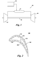
- FIG. 1 is a schematic diagram of a gas turbine system 10.
- the system 10 may include one or more compressors 12, combustors 14, turbines 16, and fuel nozzles 20.
- the compressor 12 and turbine 16 may be coupled by one or more shaft 18.
- the shaft 18 may be a single shaft or multiple shaft segments coupled together to form shaft 18.
- the gas turbine system 10 may include a number of hot gas path components 100.
- a hot gas path component is any component of the system 10 that is at least partially exposed to a high temperature flow of gas through the system 10.
- bucket assemblies also known as blades or blade assemblies
- nozzle assemblies also known as vanes or vane assemblies
- shroud assemblies transition pieces, retaining rings, and compressor exhaust components are all hot gas path components.
- the hot gas path component 100 of the present invention is not limited to the above examples, but may be any component that is at least partially exposed to a high temperature flow of gas.
- the hot gas path component 100 of the present disclosure is not limited to components in gas turbine systems 10, but may be any piece of machinery or component thereof that may be exposed to high temperature flows.
- the hot gas path component 100 When a hot gas path component 100 is exposed to a hot gas flow, the hot gas path component 100 is heated by the hot gas flow and may reach a temperature at which the hot gas path component 100 is substantially degraded or fails. Thus, in order to allow system 10 to operate with hot gas flow at a high temperature, increasing the efficiency, performance and/or life of the system 10, a cooling system for the hot gas path component 100 is required.
- the cooling system of the present disclosure includes a series of small channels, or micro-channels, formed in the surface of the hot gas path component 100.
- small or micro channel dimensions would encompass approximate depths and widths in the range of 0.25 mm to 1.5 mm, while for aviation sized turbine components channel dimensions would encompass approximate depths and widths in the range of 0.1 mm to 0.5 mm.
- the hot gas path component may be provided with a protective coating.
- a cooling fluid may be provided to the channels from a plenum, and the cooling fluid may flow through the channels, cooling the hot gas path component.
- the manufacturing method includes forming one or more grooves 132 in a component 100 that comprises a substrate 110 with an outer surface 112.
- the substrate 110 has at least one interior space 114.
- each groove 132 extends at least partially along the substrate 110 and has a base 134 and a top 146.
- the each groove narrows at the respective top thereof, such that each groove 132 comprises a re-entrant shaped groove 132. Re-entrant-shaped grooves are discussed in commonly assigned, US Patent Application Ser. No. 12/943,624, R.
- grooves 132 can have any configuration, for example, they may be straight, curved, or have multiple curves.
- the substrate 110 is typically cast prior to forming the groove(s) 132.
- substrate 110 may be formed from any suitable material. Depending on the intended application for component 100, this could include Ni-base, Co-base and Fe-base superalloys.
- the Ni-base superalloys may be those containing both ⁇ and ⁇ ' phases, particularly those Ni-base superalloys containing both ⁇ and ⁇ ' phases wherein the ⁇ ' phase occupies at least 40% by volume of the superalloy.
- Such alloys are known to be advantageous because of a combination of desirable properties including high temperature strength and high temperature creep resistance.
- the substrate material may also comprise a NiAl intermetallic alloy, as these alloys are also known to possess a combination of superior properties including high temperature strength and high temperature creep resistance that are advantageous for use in turbine engine applications used for aircraft.
- coated Nb-base alloys having superior oxidation resistance will be preferred, particularly those alloys comprising Nb-(27-40)Ti-(4.5-10.5)Al-(4.5-7.9)Cr-(1.5-5.5)Hf-(0-6)V, where the composition ranges are in atom per cent.
- the substrate material may also comprise a Nb-base alloy that contains at least one secondary phase, such as a Nb-containing intermetallic compound comprising a silicide, carbide or boride.
- Such alloys are composites of a ductile phase (i.e., the Nb-base alloy) and a strengthening phase (i.e., a Nb-containing intermetallic compound).
- the substrate material comprises a molybdenum based alloy, such as alloys based on molybdenum (solid solution) with Mo 5 SiB 2 and Mo 3 Si second phases.
- the substrate material comprises a ceramic matrix composite, such as a silicon carbide (SiC) matrix reinforced with SiC fibers.
- the substrate material comprises a TiAl-based intermetallic compound.
- the manufacturing method further includes processing an intermediate surface 112, 55 of the component 100 to plastically deform the surface adjacent at least one edge 135 of a respective groove 13.
- the resulting processed intermediate surface 112 is shown, for example, in FIG. 10 , and the distance across the top 146 of the groove 132 is reduced as a result of the processing, as indicated in FIGS. 9-10 .
- the manufacturing method improves the ability of coatings to bridge the opening directly (that is, without the use of a sacrificial filler). By reducing one of the machining specifications, the manufacturing method may reduce the machining cost for the channels.
- the grooves 132 may be formed using a variety of techniques.
- Example techniques for forming the groove(s) 132 include abrasive liquid jet, plunge electrochemical machining (ECM), electric discharge machining (EDM) with a spinning electrode (milling EDM), and laser machining.
- Example laser machining techniques are described in commonly assigned, US Patent Application Ser. No. 12/697,005 , "Process and system for forming shaped air holes” filed January 29, 2010, which is incorporated by reference herein in its entirety.
- Example EDM techniques are described in commonly assigned US Patent Application Ser. No. 12/790,675 , "Articles which include chevron film cooling holes, and related processes," filed May 28, 2010, which is incorporated by reference herein in its entirety.
- the grooves are formed using an abrasive liquid jet 160 ( FIG. 6 ).
- Example water jet drilling processes and systems are provided in commonly assigned US Patent Application Ser. No. 12/790,675 , "Articles which include chevron film cooling holes, and related processes," filed May 28, 2010, which is incorporated by reference herein in its entirety.
- the water jet process typically utilizes a high-velocity stream of abrasive particles (e.g., abrasive "grit”), suspended in a stream of high pressure water.
- the pressure of the water may vary considerably, but is often in the range of about 35-620 MPa.
- a number of abrasive materials can be used, such as garnet, aluminum oxide, silicon carbide, and glass beads.
- abrasive liquid jet machining techniques facilitates the removal of material in stages to varying depths, with control of the shaping. This allows the interior access holes 140 feeding the channel to be drilled either as a straight hole of constant cross section, a shaped hole (elliptical etc.), or a converging or diverging hole as shown.
- the water jet system can include a multi-axis computer numerically controlled (CNC) unit 210 ( FIG. 6 ).
- CNC computer numerically controlled
- the CNC systems themselves are known in the art, and described, for example, in U.S. Patent Publication 1005/0013926 (S. Rutkowski et al ), which is incorporated herein by reference. CNC systems allow movement of the cutting tool along a number of X, Y, and Z axes, as well as rotational axes.
- the intermediate surface 112, 55 of the component 100 may be processed using one or more of a variety of techniques, including without limitation, shot peening the intermediate surface 112, 55, water jet peening the intermediate surface 112, 55, flapper peening the intermediate surface 112, 55, gravity peening the intermediate surface 112, 55, ultrasonic peening the intermediate surface 112, 55, burnishing the intermediate surface 112, 55, low-plasticity burnishing the intermediate surface 112, 55, and laser shock peening the intermediate surface 112, 55, to deform the edge(s) 135 of the groove, such that the distance across the top 146 of the groove 132 is reduced.
- the intermediate surface 112, 55 of the component 100 is processed by shot peening.
- shot peening typically introduces a number of surface irregularities in the intermediate surface 112, 55 of the component 100.
- the surface irregularities may aid in the bridging of coatings deposited over the surface, and especially coatings deposited using ion plasma deposition, electron beam physical vapor deposition, and sputtering.
- the intermediate surface 112, 55 of the component 100 is processed by burnishing the intermediate surface 112, 55.
- burnishing techniques may be employed, depending on the material being surface treated and on the desired deformation.
- Non-limiting examples of burnishing techniques include plastically massaging the intermediate surface of the component, for example using rollers, pins, or balls, and low plasticity burnishing.
- the distance across the top of the groove will vary based on the specific application. However, for certain configurations, the distance across the top 146 of the groove 132 is in a range of about 8 - 25 mil (0.2 - 0.6 mm) prior to processing the intermediate surface 112, 55 of the component 100, and the distance across the top 146 of the groove 132 is in a range of about 0 - 15 mil (0-0.4 mm) after the intermediate surface 112, 55 has been processed.
- the step of processing the intermediate surface 112, 55 of the component 100 also facets the intermediate surface 112, 55 in the vicinity of the groove 132.
- faceting should be understood to tilt the intermediate surface in the vicinity of the groove inward, as indicated, for example, in the circled regions in FIG. 10 .
- the grooves 132 may be formed in the substrate 110 ( FIGS. 2-8 ) or in an inner layer of a structural coating 54, as described below with reference to FIG. 11 .
- the intermediate surface 112 that is processed comprises the outer surface 112 of the substrate 110, as indicated for example in FIGS. 9 and 10 .
- the outer surface 112 of the substrate 110 is processed to deform at least one edge 135 of the respective groove 132, as shown in FIG. 9 (before processing) and FIG. 10 (after processing).
- the manufacturing method may further include disposing a coating 150 over at least a portion of the intermediate surface 112 (see FIGS. 4 and 5 ), 55 (see FIG. 11 ) of the component 110.
- the groove(s) 132 and the coating 150 define one or more channels 130 for cooling the component 100.
- Coating 150 comprises a suitable material and is bonded to the component.
- the coating 150 has a thickness in the range of 0.1-2.0 millimeters, and more particularly, in the range of 0.2 to 1 millimeter, and still more particularly 0.2 to 0.5 millimeters for industrial components. For aviation components, this range is typically 0.1 to 0.25 millimeters. However, other thicknesses may be utilized depending on the requirements for a particular component 100.
- the coating 150 comprises structural coating layers and may further include optional additional coating layer(s).
- the coating layer(s) may be deposited using a variety of techniques. For particular processes, the structural coating layer(s) are deposited by performing an ion plasma deposition (cathodic arc).
- Example ion plasma deposition apparatus and method are provided in commonly assigned, US Published Patent Application No. 10080138529, Weaver et al , "Method and apparatus for cathodic arc ion plasma deposition," which is incorporated by reference herein in its entirety.
- ion plasma deposition comprises placing a consumable cathode formed of a coating material into a vacuum environment within a vacuum chamber, providing a substrate 110 within the vacuum environment, supplying a current to the cathode to form a cathodic arc upon a cathode surface resulting in arc-induced erosion of coating material from the cathode surface, and depositing the coating material from the cathode upon the substrate surface 112.
- Non-limiting examples of a coating deposited using ion plasma deposition include structural coatings, as well as bond coatings and oxidation-resistant coatings, as discussed in greater detail below with reference to US Patent No. 5,626,462, Jackson et al .,"Double-wall airfoil.”
- the structural coating comprises a nickel-based or cobalt-based alloy, and more particularly comprises a superalloy or a (Ni,Co)CrAlY alloy.
- structural coating may comprise similar compositions of materials, as discussed in greater detail below with reference to US Patent No. 5,626,462 .
- a structural coating is deposited by performing at least one of a thermal spray process and a cold spray process.
- the thermal spray process may comprise combustion spraying or plasma spraying
- the combustion spraying may comprise high velocity oxygen fuel spraying (HVOF) or high velocity air fuel spraying (HVAF)
- the plasma spraying may comprise atmospheric (such as air or inert gas) plasma spray, or low pressure plasma spray (LPPS, which is also known as vacuum plasma spray or VPS).
- LPPS low pressure plasma spray
- a (Ni,Co)CrAlY coating is deposited by HVOF or HVAF.
- Other example techniques for depositing the structural coating include, without limitation, sputtering, electron beam physical vapor deposition, electroless plating, and electroplating.
- a first structural coating layer may be deposited using an ion plasma deposition, and a subsequently deposited layer and optional additional layers (not shown) may be deposited using other techniques, such as a combustion spray process or a plasma spray process.
- a combustion spray process or a plasma spray process.
- the use of different deposition techniques for the coating layers may provide benefits in properties, such as, but not restricted to strain tolerance, strength, adhesion, and/or ductility.
- the coating 150 comprises an outer layer of a structural coating
- the manufacturing method further includes depositing an inner layer of the structural coating 54 on the outer surface 112 of the substrate 110 prior to forming the grooves 132.
- the grooves 132 are formed at least partially in the inner structural coating 54, such that the intermediate surface 55 that is processed comprises the upper surface 55 of the inner layer 54 of the structural coating.
- the upper surface 55 of the inner layer 54 of the structural coating is processed (similar to the process illustrated by FIGS. 9 and 10 ) to deform at least one edge 135 of the respective groove 132. It should be noted, that although the grooves shown in FIG.
- the grooves 132 do not extend into the substrate 110, for other configurations the grooves extend through the inner layer 54 of the structural coating and extend into the substrate 110. However, for many configurations, the grooves 132 are formed entirely in the substrate 110 (as discussed above with reference to FIGS. 9 and 10 ), and the coating layers are deposited after the grooves 132 have been formed.
- the above-described manufacturing method reduces the top surface opening size of the grooves.
- reduced channel opening size markedly enhances the ability of coatings to bridge the opening directly (without the use of a sacrificial filler)
- machining specifications may be relaxed, such that, for example, relatively large abrasive liquid jet nozzles may be employed, reducing machining time and cost.
- the manufacturing method includes forming one or more grooves 132 in a component 100 that comprises a substrate 110 with an outer surface 112. Techniques for forming the grooves 132 are described above.
- the substrate 110 has at least one interior space 114.
- each groove 132 extends at least partially along the substrate 110 and has a base 134 and a top 146.
- each groove narrows at the respective top thereof, such that each groove 132 comprises a re-entrant shaped groove 132.
- re-entrant-shaped grooves are discussed in commonly assigned, US Patent Application Ser. No. 12/943,624, Bunker et al. , "Components with re-entrant shaped cooling channels and methods of manufacture.”
- the manufacturing method further includes processing an intermediate surface 112, 55 of the component 100 to facet the intermediate surface 112, 55 in a vicinity of the groove 132.
- faceting should be understood to tilt the intermediate surface inward in the vicinity of the groove, as indicated for example, in FIG. 10 .
- tilting the intermediate surface inward in the vicinity of the groove improves the bridging of the coating over the groove opening (without the use of a sacrificial filler), such that the mechanical specifications for the groove opening may be relaxed, facilitating the use of a larger water jet nozzle to form the grooves. This would reduce the time needed to for the grooves as well as the associated machining cost.
- the manufacturing method typically further includes casting the substrate 110 prior to forming the groove(s) 132.
- suitable techniques for forming the groove(s) include, without limitation, abrasive liquid jet, plunge electrochemical machining (ECM), electric discharge machining (EDM) with a spinning electrode (milling EDM), and laser machining.
- suitable techniques for processing the intermediate surface 112, 55 of the component 100 include, without limitation, shot peening, water peening, flapper peening, gravity peening, ultrasonic peening, burnishing, and laser shock peening. More particularly, processing the intermediate surface 112, 55 plastically deforms the surface adjacent the edge(s) 135 of the groove, such that the distance across the top 146 of the groove 132 is reduced.
- the intermediate surface 112, 55 of the component 100 is shot peened. As indicated, for example in FIG. 8 , the shot peening introduces multiple surface irregularities in the intermediate surface 112, 55 of the component 100.
- the grooves 132 may be formed in the substrate 110 or in an inner layer of a structural coating 54 ( FIG. 11 ).
- the intermediate surface 112 that is processed comprises the outer surface 112 of the substrate 110, as indicated for example in FIGS. 9 and 10 .
- the outer surface 112 of the substrate 110 is processed to facet the intermediate surface 112, 55 in a vicinity of the groove 132, as shown in FIG. 9 (before processing) and FIG. 10 (after processing).
- the grooves 132 are formed at least partially in the inner structural coating 54, such that the intermediate surface 55 that is processed comprises the upper surface 55 of the inner layer 54 of the structural coating.
- the upper surface 55 of the inner layer 54 of the structural coating is processed to facet the intermediate surface 55 in the vicinity of the groove 132.
- the component 100 includes a substrate 110 comprising an outer surface 112 and an inner surface 116.
- the inner surface 116 defines at least one hollow, interior space 114.
- the component 100 defines one or more grooves 132.
- Each groove 132 extends at least partially along the substrate 110 and has a base 134 and a top 146.
- each groove narrows at the respective top thereof, such that each groove 132 comprises a re-entrant shaped groove 132.
- FIG. 4 each groove narrows at the respective top thereof, such that each groove 132 comprises a re-entrant shaped groove 132.
- an intermediate surface 112, 55 of the component 100 is faceted in the vicinity of the respective groove 132.
- one or more access holes 140 are formed through the base 134 of a respective groove 132, to connect the groove 132 in fluid communication with the respective hollow interior space 114. It should be noted that the access holes 140 are holes and are thus not coextensive with the channels 130, as indicated in FIG. 4 , for example.
- at least one coating 150 is disposed over at least a portion of the surface 112 of the substrate 110.
- the groove(s) 132 and the coating 150 together define one or more re-entrant shaped channels 130 for cooling the component 100.
- the bridging of the coating over faceted portions of the intermediate surface 112, 55 of the component 100 enhances bridging relative to an unfaceted surface.
- a number of surface irregularities are formed in the intermediate surface 112 of the component 100 in the vicinity of the respective groove 132.
- these surface irregularities have added surface area (relative to a smooth surface) which may enhance the adhesion to the coating.
Landscapes
- Engineering & Computer Science (AREA)
- Mechanical Engineering (AREA)
- General Engineering & Computer Science (AREA)
- Architecture (AREA)
- Chemical & Material Sciences (AREA)
- Materials Engineering (AREA)
- Turbine Rotor Nozzle Sealing (AREA)
Applications Claiming Priority (1)
| Application Number | Priority Date | Filing Date | Title |
|---|---|---|---|
| US13/242,179 US20130078418A1 (en) | 2011-09-23 | 2011-09-23 | Components with cooling channels and methods of manufacture |
Publications (1)
| Publication Number | Publication Date |
|---|---|
| EP2573320A2 true EP2573320A2 (en) | 2013-03-27 |
Family
ID=46967990
Family Applications (1)
| Application Number | Title | Priority Date | Filing Date |
|---|---|---|---|
| EP12184391A Withdrawn EP2573320A2 (en) | 2011-09-23 | 2012-09-14 | Components with cooling channels and methods of manufacture |
Country Status (3)
| Country | Link |
|---|---|
| US (1) | US20130078418A1 (zh) |
| EP (1) | EP2573320A2 (zh) |
| CN (1) | CN103009024A (zh) |
Cited By (2)
| Publication number | Priority date | Publication date | Assignee | Title |
|---|---|---|---|---|
| EP2728033A1 (en) * | 2012-10-30 | 2014-05-07 | General Electric Company | Components with micro cooled patterned coating layer and methods of manufacture |
| EP2728034A1 (en) * | 2012-10-30 | 2014-05-07 | General Electric Company | Components with micro cooled coating layer and methods of manufacture |
Families Citing this family (7)
| Publication number | Priority date | Publication date | Assignee | Title |
|---|---|---|---|---|
| US8387245B2 (en) * | 2010-11-10 | 2013-03-05 | General Electric Company | Components with re-entrant shaped cooling channels and methods of manufacture |
| US9249491B2 (en) * | 2010-11-10 | 2016-02-02 | General Electric Company | Components with re-entrant shaped cooling channels and methods of manufacture |
| US20120243995A1 (en) * | 2011-03-21 | 2012-09-27 | General Electric Company | Components with cooling channels formed in coating and methods of manufacture |
| DE102013109116A1 (de) | 2012-08-27 | 2014-03-27 | General Electric Company (N.D.Ges.D. Staates New York) | Bauteil mit Kühlkanälen und Verfahren zur Herstellung |
| US10422244B2 (en) | 2015-03-16 | 2019-09-24 | General Electric Company | System for cooling a turbine shroud |
| CN106312462A (zh) * | 2016-11-02 | 2017-01-11 | 贵州航飞精密制造有限公司 | 一种特长薄壁零件的加工工艺 |
| CN114952587A (zh) * | 2022-06-28 | 2022-08-30 | 中国航发北京航空材料研究院 | 一种航空发动机涡轮叶片气膜孔倒角的加工方法 |
Citations (3)
| Publication number | Priority date | Publication date | Assignee | Title |
|---|---|---|---|---|
| US5626462A (en) | 1995-01-03 | 1997-05-06 | General Electric Company | Double-wall airfoil |
| US20050013926A1 (en) | 2003-07-17 | 2005-01-20 | General Electric Company | Robotic pen |
| US20080138529A1 (en) | 2006-12-11 | 2008-06-12 | Ge Global Research Center | Method and apparatus for cathodic arc ion plasma deposition |
Family Cites Families (10)
| Publication number | Priority date | Publication date | Assignee | Title |
|---|---|---|---|---|
| US5313038A (en) * | 1992-12-22 | 1994-05-17 | United Technologies Corporation | EDM drilling of low angle holes |
| US6494678B1 (en) * | 2001-05-31 | 2002-12-17 | General Electric Company | Film cooled blade tip |
| US20040265488A1 (en) * | 2003-06-30 | 2004-12-30 | General Electric Company | Method for forming a flow director on a hot gas path component |
| EP1555329A1 (de) * | 2004-01-15 | 2005-07-20 | Siemens Aktiengesellschaft | Bauteil mit Druckeigenspannungen, Verfahren zur Herstellung und Vorrichtung zur Erzeugung von Druckeigenspannungen |
| US7186091B2 (en) * | 2004-11-09 | 2007-03-06 | General Electric Company | Methods and apparatus for cooling gas turbine engine components |
| US7967924B2 (en) * | 2005-05-17 | 2011-06-28 | General Electric Company | Method for making a compositionally graded gas turbine disk |
| US7322795B2 (en) * | 2006-01-27 | 2008-01-29 | United Technologies Corporation | Firm cooling method and hole manufacture |
| US7766617B1 (en) * | 2007-03-06 | 2010-08-03 | Florida Turbine Technologies, Inc. | Transpiration cooled turbine airfoil |
| US8846206B2 (en) * | 2008-07-31 | 2014-09-30 | Siemens Energy, Inc. | Injection molded component |
| US8292587B2 (en) * | 2008-12-18 | 2012-10-23 | Honeywell International Inc. | Turbine blade assemblies and methods of manufacturing the same |
-
2011
- 2011-09-23 US US13/242,179 patent/US20130078418A1/en not_active Abandoned
-
2012
- 2012-09-14 EP EP12184391A patent/EP2573320A2/en not_active Withdrawn
- 2012-09-21 CN CN2012103539378A patent/CN103009024A/zh active Pending
Patent Citations (3)
| Publication number | Priority date | Publication date | Assignee | Title |
|---|---|---|---|---|
| US5626462A (en) | 1995-01-03 | 1997-05-06 | General Electric Company | Double-wall airfoil |
| US20050013926A1 (en) | 2003-07-17 | 2005-01-20 | General Electric Company | Robotic pen |
| US20080138529A1 (en) | 2006-12-11 | 2008-06-12 | Ge Global Research Center | Method and apparatus for cathodic arc ion plasma deposition |
Cited By (5)
| Publication number | Priority date | Publication date | Assignee | Title |
|---|---|---|---|---|
| EP2728033A1 (en) * | 2012-10-30 | 2014-05-07 | General Electric Company | Components with micro cooled patterned coating layer and methods of manufacture |
| EP2728034A1 (en) * | 2012-10-30 | 2014-05-07 | General Electric Company | Components with micro cooled coating layer and methods of manufacture |
| JP2014087924A (ja) * | 2012-10-30 | 2014-05-15 | General Electric Co <Ge> | マイクロ冷却される皮膜層を備えた構成要素及び製造方法 |
| US9200521B2 (en) | 2012-10-30 | 2015-12-01 | General Electric Company | Components with micro cooled coating layer and methods of manufacture |
| US9562436B2 (en) | 2012-10-30 | 2017-02-07 | General Electric Company | Components with micro cooled patterned coating layer and methods of manufacture |
Also Published As
| Publication number | Publication date |
|---|---|
| CN103009024A (zh) | 2013-04-03 |
| US20130078418A1 (en) | 2013-03-28 |
Similar Documents
| Publication | Publication Date | Title |
|---|---|---|
| US9598963B2 (en) | Components with microchannel cooling | |
| US10822956B2 (en) | Components with cooling channels and methods of manufacture | |
| EP2604796B1 (en) | Gas turbine components with microchannel cooling | |
| US9476306B2 (en) | Components with multi-layered cooling features and methods of manufacture | |
| EP2537635B1 (en) | Component with cooling channels and method of manufacture | |
| EP2584150A2 (en) | Components with laser cladding and methods of manufacture | |
| EP2728034B1 (en) | Components with micro cooled coating layer and methods of manufacture | |
| US9249672B2 (en) | Components with cooling channels and methods of manufacture | |
| US20140302278A1 (en) | Components with double sided cooling features and methods of manufacture | |
| EP2573320A2 (en) | Components with cooling channels and methods of manufacture | |
| EP2666965B1 (en) | Component with microchannel cooled platforms and fillets and methods of manufacture | |
| EP2525044A2 (en) | Components with precision surface channels and hybrid machining method | |
| EP2537636B1 (en) | Component with cooling channels and method of manufacture | |
| US9249491B2 (en) | Components with re-entrant shaped cooling channels and methods of manufacture | |
| US10053987B2 (en) | Components with cooling channels and methods of manufacture | |
| EP2728118A2 (en) | Components with asymmetric cooling channels and methods of manufacture | |
| EP2728033B1 (en) | Methods of manufacturing components with micro cooled patterned coating layer |
Legal Events
| Date | Code | Title | Description |
|---|---|---|---|
| PUAI | Public reference made under article 153(3) epc to a published international application that has entered the european phase |
Free format text: ORIGINAL CODE: 0009012 |
|
| AK | Designated contracting states |
Kind code of ref document: A2 Designated state(s): AL AT BE BG CH CY CZ DE DK EE ES FI FR GB GR HR HU IE IS IT LI LT LU LV MC MK MT NL NO PL PT RO RS SE SI SK SM TR |
|
| AX | Request for extension of the european patent |
Extension state: BA ME |
|
| STAA | Information on the status of an ep patent application or granted ep patent |
Free format text: STATUS: THE APPLICATION IS DEEMED TO BE WITHDRAWN |
|
| 18D | Application deemed to be withdrawn |
Effective date: 20160401 |