EP2573246B1 - Electrical household appliance - Google Patents
Electrical household appliance Download PDFInfo
- Publication number
- EP2573246B1 EP2573246B1 EP12179195.8A EP12179195A EP2573246B1 EP 2573246 B1 EP2573246 B1 EP 2573246B1 EP 12179195 A EP12179195 A EP 12179195A EP 2573246 B1 EP2573246 B1 EP 2573246B1
- Authority
- EP
- European Patent Office
- Prior art keywords
- coolant
- household appliance
- passage
- electrical household
- area
- Prior art date
- Legal status (The legal status is an assumption and is not a legal conclusion. Google has not performed a legal analysis and makes no representation as to the accuracy of the status listed.)
- Active
Links
- 239000002826 coolant Substances 0.000 claims description 61
- 239000012530 fluid Substances 0.000 claims description 41
- 238000009833 condensation Methods 0.000 claims description 40
- 230000005494 condensation Effects 0.000 claims description 40
- 238000001035 drying Methods 0.000 claims description 37
- 238000007599 discharging Methods 0.000 claims description 15
- 238000005406 washing Methods 0.000 claims description 15
- 239000007788 liquid Substances 0.000 claims description 7
- 238000011144 upstream manufacturing Methods 0.000 claims description 6
- 229910052751 metal Inorganic materials 0.000 claims description 4
- 239000002184 metal Substances 0.000 claims description 4
- 230000003134 recirculating effect Effects 0.000 claims 1
- XLYOFNOQVPJJNP-UHFFFAOYSA-N water Substances O XLYOFNOQVPJJNP-UHFFFAOYSA-N 0.000 description 10
- 239000000498 cooling water Substances 0.000 description 4
- 230000007613 environmental effect Effects 0.000 description 3
- 238000010981 drying operation Methods 0.000 description 2
- 239000002699 waste material Substances 0.000 description 2
- 239000000654 additive Substances 0.000 description 1
- WYTGDNHDOZPMIW-RCBQFDQVSA-N alstonine Natural products C1=CC2=C3C=CC=CC3=NC2=C2N1C[C@H]1[C@H](C)OC=C(C(=O)OC)[C@H]1C2 WYTGDNHDOZPMIW-RCBQFDQVSA-N 0.000 description 1
- 239000004411 aluminium Substances 0.000 description 1
- 229910052782 aluminium Inorganic materials 0.000 description 1
- XAGFODPZIPBFFR-UHFFFAOYSA-N aluminium Chemical compound [Al] XAGFODPZIPBFFR-UHFFFAOYSA-N 0.000 description 1
- 230000000903 blocking effect Effects 0.000 description 1
- 239000000284 extract Substances 0.000 description 1
- 230000005484 gravity Effects 0.000 description 1
- 238000000034 method Methods 0.000 description 1
- 238000004064 recycling Methods 0.000 description 1
- 238000007493 shaping process Methods 0.000 description 1
- 239000000126 substance Substances 0.000 description 1
Images
Classifications
-
- D—TEXTILES; PAPER
- D06—TREATMENT OF TEXTILES OR THE LIKE; LAUNDERING; FLEXIBLE MATERIALS NOT OTHERWISE PROVIDED FOR
- D06F—LAUNDERING, DRYING, IRONING, PRESSING OR FOLDING TEXTILE ARTICLES
- D06F25/00—Washing machines with receptacles, e.g. perforated, having a rotary movement, e.g. oscillatory movement, the receptacle serving both for washing and for centrifugally separating water from the laundry and having further drying means, e.g. using hot air
-
- A—HUMAN NECESSITIES
- A47—FURNITURE; DOMESTIC ARTICLES OR APPLIANCES; COFFEE MILLS; SPICE MILLS; SUCTION CLEANERS IN GENERAL
- A47L—DOMESTIC WASHING OR CLEANING; SUCTION CLEANERS IN GENERAL
- A47L15/00—Washing or rinsing machines for crockery or tableware
- A47L15/42—Details
- A47L15/48—Drying arrangements
- A47L15/483—Drying arrangements by using condensers
-
- D—TEXTILES; PAPER
- D06—TREATMENT OF TEXTILES OR THE LIKE; LAUNDERING; FLEXIBLE MATERIALS NOT OTHERWISE PROVIDED FOR
- D06F—LAUNDERING, DRYING, IRONING, PRESSING OR FOLDING TEXTILE ARTICLES
- D06F39/00—Details of washing machines not specific to a single type of machines covered by groups D06F9/00 - D06F27/00
- D06F39/006—Recovery arrangements, e.g. for the recovery of energy or water
-
- D—TEXTILES; PAPER
- D06—TREATMENT OF TEXTILES OR THE LIKE; LAUNDERING; FLEXIBLE MATERIALS NOT OTHERWISE PROVIDED FOR
- D06F—LAUNDERING, DRYING, IRONING, PRESSING OR FOLDING TEXTILE ARTICLES
- D06F58/00—Domestic laundry dryers
- D06F58/20—General details of domestic laundry dryers
- D06F58/24—Condensing arrangements
-
- D—TEXTILES; PAPER
- D06—TREATMENT OF TEXTILES OR THE LIKE; LAUNDERING; FLEXIBLE MATERIALS NOT OTHERWISE PROVIDED FOR
- D06F—LAUNDERING, DRYING, IRONING, PRESSING OR FOLDING TEXTILE ARTICLES
- D06F58/00—Domestic laundry dryers
- D06F58/20—General details of domestic laundry dryers
- D06F58/206—Heat pump arrangements
-
- Y—GENERAL TAGGING OF NEW TECHNOLOGICAL DEVELOPMENTS; GENERAL TAGGING OF CROSS-SECTIONAL TECHNOLOGIES SPANNING OVER SEVERAL SECTIONS OF THE IPC; TECHNICAL SUBJECTS COVERED BY FORMER USPC CROSS-REFERENCE ART COLLECTIONS [XRACs] AND DIGESTS
- Y02—TECHNOLOGIES OR APPLICATIONS FOR MITIGATION OR ADAPTATION AGAINST CLIMATE CHANGE
- Y02B—CLIMATE CHANGE MITIGATION TECHNOLOGIES RELATED TO BUILDINGS, e.g. HOUSING, HOUSE APPLIANCES OR RELATED END-USER APPLICATIONS
- Y02B40/00—Technologies aiming at improving the efficiency of home appliances, e.g. induction cooking or efficient technologies for refrigerators, freezers or dish washers
Definitions
- the present invention relates to an electrical household appliance for drying items such as laundry or dishes.
- the electrical household appliance could also be a washer-dryer or a dishwasher in which prior to the drying action there is envisaged a washing action.
- An electrical household drying appliance in which there is a plastic duct extending between a compartment for drying the laundry and an impeller that extracts moist air from the compartment is well known.
- the cooling water and condensed steam will flow by gravity toward a common drainage conduit that enables it to be extracted from the duct and conveyed toward a drain.
- a drawback of this constructive solution is tied to problems of an economic nature tied to the high consumption of cooling water (which is precisely water in order to contain the costs of the washing liquid).
- a further drawback is tied to the fact that there is a high consumption of an environmental resource (water, precisely).
- Patent EP2241663A1 discloses a washing-drying machine for performing washing and drying operations, having an articles storing chamber connected to water/air heat exchanger; the machine improves energy efficiency, and saves water and energy during washing and drying operations.
- the technical task at the basis of the present invention is to propose an electrical household appliance which overcomes the above-mentioned drawbacks of the prior art.
- the reference number 1 indicates an electrical household appliance for drying items (for example laundry or dishes).
- electrical household appliances capable of performing this function are: dryers, washer-dryers (in which in addition to the possibility of drying, there is also provided the possibility of washing the laundry), and dishwashers (incorporating means for drying the dishes which are usually actuated after washing).
- a washer-dryer is illustrated by way of example.
- the electrical household appliance 1 comprises:
- the discharging conduit 3 is at least in part operatively interposed between said drying compartment 2 and an impeller 5 which draws the gaseous fluid (typically moist air) from the drying compartment 2. Downstream of the impeller 5, the gaseous fluid is advantageously heated, for example by means of a resistor, and reintroduced into the drying compartment 2.
- the drying compartment 2 is in part delimited by a door 6 for accessing the drying compartment 2 and a wall 60 opposite the door 6.
- the discharging conduit 3 extends from said wall 60 opposite the door 6. The discharging conduit 3 reintroduces the gaseous fluid into the drying compartment 2 in a front portion of the drying compartment 2 (in proximity to the door 6). The gaseous fluid from which the moisture was removed and conveniently heated is thus reused to dry the items.
- the electrical household appliance 1 comprises a path 8 for conveying a coolant.
- the electrical household appliance 1 comprises a condenser 4 in which there is an exchange of heat between the discharging conduit 3 and the path 8 for conveying the coolant.
- the condenser 4 permits the condensation of at least a part of the steam present in the gaseous fluid.
- the condenser 4 is constrained to at least one wall delimiting the drying compartment 2 (typically the wall 60 opposite the door 6).
- the impeller 5 is preferably situated downstream of the condenser 4 and upstream of the drying compartment 2 relative to the direction of flow of the coolant.
- the condenser 4 comprises:
- the first stretch 81 of the channel 42 for passage of the coolant extends substantially alongside the area 41 for passage of the gaseous fluid.
- the first stretch 81 of the channel 42 for passage of the coolant is serpentine. This enables the heat exchange with the gaseous fluid to be improved considerably.
- the first condensation wall 400 extends substantially parallel to a plane.
- the first condensation wall 400 is planar.
- the first stretch 81 of the channel 42 for passage of the coolant extends substantially parallel to a plane.
- the condenser 4 comprises a first and second metal sheet 83, 84, superposed and comprising a first portion 85 in which the first and the second sheet 83, 84 are joined together and a second portion 86 in which the first and the second sheet 83, 84 are spaced apart so as to form interposed between them the first stretch 81 of the channel 42 for passage of the coolant.
- the first and the second sheet 83, 84 are joined together and could be indistinguishable.
- the first and the second metal sheet 83, 84 are irremovably joined to each other (according to a technique known as "roll bonding").
- the first stretch 81 of the channel 42 can include a plurality of sections extending vertically or horizontally side by side and connected to one another so as to form a serpentine path (see for example figure 6 ).
- the condenser 4 comprises a shell 461.
- the shell 461 comprises a cover 462 blocking off a slot for introducing at least the first condensation wall 400.
- the condenser 4 comprises a second condensation area 82.
- the first and the second condensation area 40, 82 lie on two opposite walls of a body in which said first stretch 81 of the channel 42 for passage of the coolant is formed.
- the area 41 for passage of the gaseous fluid touches both the first and the second metal sheet 83, 84. At least a part of the first condensation area 40 is integrated in said first sheet 83, at least a part of said second condensation area 82 being integrated in the second sheet 84.
- the first stretch 81 of the channel 42 for passage of the coolant is interposed between two parts of the area 41 for passage of the gaseous fluid.
- the area 41 for passage of the gaseous fluid, downstream of an inlet of said condenser 4, includes a ramification induced by the presence of said body in which the first stretch 81 of the channel 42 for passage of the coolant is formed.
- the area 41 for passage of the gaseous fluid comprises a reconvergence downstream of said body and upstream of an outlet of said condenser 4.
- the second condensation area 82 is a second condensation wall.
- the passage area 41 comprises two main sections 71, 72 transverse to each other (for example, substantially orthogonal).
- the channel 42 for passage of the coolant extends along only one of the two main sections.
- the shell 461 comprises an external delimiting surface 45 in turn comprising:
- said area 41 for passage of the gaseous fluid touches a wall comprising the first face 73 and a wall comprising the second face 74.
- the shell 461 comprises:
- the electrical household appliance 1 is a washer-dryer or a dishwasher in which said drying compartment 2 coincides with a washing compartment 2.
- a washing treatment is thus carried out by the electrical household appliance 1 in addition to drying.
- a rotating basket is typically placed inside the washing compartment 2.
- at least one extractible rack for positioning the dishes is conveniently present.
- the electrical household appliance 1 comprises means 9 for drawing air from outside the electrical household appliance 1.
- the air is drawn from a front face of the electrical household appliance (the front face is the one comprising the door 6). This minimises the risk of there being obstructions that impede drawing air.
- the drawing means 9 further comprise a heat exchanger 91 which places in thermal communication a stretch of the path 8 for conveying the coolant and the air drawn by the drawing means 9. The outside air is thus used to cool the coolant which has been heated after removing heat from the moist gaseous fluid discharged from the drying compartment 2.
- the drawing means 9 comprise:
- the conveying duct 94 leads to the inside of the machine body 97.
- the conveying duct 94 leads to the outside of the machine body 97.
- it leads out from a rear face 99 of the electrical household appliance 1 (typically a face of the electrical household appliance which is opposite the one comprising the door 6).
- the air exits from the machine body 97 after having passed through the heat exchanger 91.
- the electrical household appliance 1 comprises means 95 for moving the coolant positioned along the path 8 for conveying the coolant.
- the coolant can be liquid or gaseous.
- the coolant is usually liquid and the movement means 95 typically comprise a pump; if the coolant is gaseous, the movement means 95 could comprise a compressor.
- the electrical household appliance 1 comprises a storage vessel 96 designed to accommodate said coolant and positioned along the path 8 for conveying the coolant.
- the vessel 96 is used, for example, to allow the coolant to be initially introduced into the conveying path 8 from the outside (this operation is carried out prior to use).
- the vessel 96 is positioned downstream of said condenser 4 and upstream of said movement means 95 along the direction of flow of the coolant.
- the heat exchanger 91 is positioned downstream of said movement means 95 and upstream of said condenser 4 along the direction of flow of the coolant.
- the electrical household appliance 1 comprises a channel 47 for draining the condensation, the channel 47 being outside the area 41 for passage of the gaseous fluid.
- the draining channel 47 places the area 41 for passage of the gaseous fluid in fluid communication with the washing compartment 2. This also enables the condensation that forms in the condenser 4 to be discharged through drainage means used for discharging the washing liquid (previously used).
- the condensation can return into the drying compartment 2 through a connecting interface between the discharging conduit 3 and the drying compartment 2 (the interface is said inlet 421 which enables the gaseous fluid to be extracted from the drying compartment 2).
- the interface is said inlet 421 which enables the gaseous fluid to be extracted from the drying compartment 2.
- a lower portion of the shell 461 forms a condensation collection receptacle, above which the inlet 421 is positioned. When the level of condensation in the collection receptacle rises above the lower edge of the inlet 421, the condensation overflows into the drying compartment 2.
- the condensation can be discharged from the drying compartment 2 by drainage means used for discharging the washing liquid of the electrical household appliance.
Description
- The present invention relates to an electrical household appliance for drying items such as laundry or dishes. The electrical household appliance could also be a washer-dryer or a dishwasher in which prior to the drying action there is envisaged a washing action.
- An electrical household drying appliance in which there is a plastic duct extending between a compartment for drying the laundry and an impeller that extracts moist air from the compartment is well known.
- Along the inner surface of said duct there are a plurality of outlets for the cooling water coming from the mains water supply. The cooling water sprayed inside the duct causes the condensation of part of the moisture present in the air extracted from the drying compartment.
- The cooling water and condensed steam will flow by gravity toward a common drainage conduit that enables it to be extracted from the duct and conveyed toward a drain.
- A drawback of this constructive solution is tied to problems of an economic nature tied to the high consumption of cooling water (which is precisely water in order to contain the costs of the washing liquid). A further drawback is tied to the fact that there is a high consumption of an environmental resource (water, precisely).
- Document
EP2241663A1 discloses a washing-drying machine for performing washing and drying operations, having an articles storing chamber connected to water/air heat exchanger; the machine improves energy efficiency, and saves water and energy during washing and drying operations. - In this context, the technical task at the basis of the present invention is to propose an electrical household appliance which overcomes the above-mentioned drawbacks of the prior art.
- In particular, it is an object of the present invention to provide an electrical household appliance capable of reducing operating costs. A further object is to minimise the consumption of environmental resources.
- The stated technical task and the specified objects are substantially achieved by an electrical household appliance comprising the technical features set forth in one or more of the appended claims.
- Additional features and advantages of the present invention will be more apparent from the approximate, and hence non-restrictive description of a preferred but non-exclusive embodiment of an electrical household appliance, as illustrated in the appended drawings, in which:
-
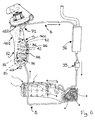
figure 1 shows a schematic side view of an electrical household appliance according to the present invention; -
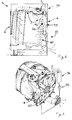
figure 2 shows a rear perspective view of components of an electrical household appliance according to the present invention; -
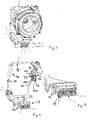
figure 3 shows a front perspective view of components of an electrical household appliance according to the present invention; -
figures 4 and6 show two perspective views of functional components of the electrical household appliance according to the present invention; -
figure 5 shows an enlarged detail offigure 4 . - In the appended drawings, the reference number 1 indicates an electrical household appliance for drying items (for example laundry or dishes). Examples of electrical household appliances capable of performing this function are: dryers, washer-dryers (in which in addition to the possibility of drying, there is also provided the possibility of washing the laundry), and dishwashers (incorporating means for drying the dishes which are usually actuated after washing). In the appended figures a washer-dryer is illustrated by way of example.
- The electrical household appliance 1 comprises:
- i) a compartment 2 for drying said items;
- ii) a
conduit 3 for discharging a gaseous fluid from the drying compartment 2 (typically the gaseous fluid is moist air). - Conveniently, the
discharging conduit 3 is at least in part operatively interposed between said drying compartment 2 and an impeller 5 which draws the gaseous fluid (typically moist air) from the drying compartment 2. Downstream of the impeller 5, the gaseous fluid is advantageously heated, for example by means of a resistor, and reintroduced into the drying compartment 2. Conveniently, the drying compartment 2 is in part delimited by a door 6 for accessing the drying compartment 2 and awall 60 opposite the door 6. In the non-restrictive example embodiment illustrated in the appended figures, thedischarging conduit 3 extends fromsaid wall 60 opposite the door 6. Thedischarging conduit 3 reintroduces the gaseous fluid into the drying compartment 2 in a front portion of the drying compartment 2 (in proximity to the door 6). The gaseous fluid from which the moisture was removed and conveniently heated is thus reused to dry the items. - The electrical household appliance 1 comprises a
path 8 for conveying a coolant. - Conveniently, the electrical household appliance 1 comprises a
condenser 4 in which there is an exchange of heat between thedischarging conduit 3 and thepath 8 for conveying the coolant. Thecondenser 4 permits the condensation of at least a part of the steam present in the gaseous fluid. Conveniently, thecondenser 4 is constrained to at least one wall delimiting the drying compartment 2 (typically thewall 60 opposite the door 6). The impeller 5 is preferably situated downstream of thecondenser 4 and upstream of the drying compartment 2 relative to the direction of flow of the coolant. - The
condenser 4 comprises: - an
area 41 for passage of the gaseous fluid arriving from the drying compartment 2; saidarea 41 for passage of the gaseous fluid is integrated in theconduit 3 for discharging the gaseous fluid; - a
channel 42 for passage of a coolant; thechannel 42 for passage of the coolant is integrated in thepath 8 for conveying the coolant. Typically the coolant is liquid, in particular it is water (possibly supplemented with chemical additives). Thepath 8 for conveying the coolant comprises a circuit that extends along a closed line. The circuit in turn integrates saidchannel 42 for passage of the coolant to allow at least partial recirculation of the coolant. The circuit is thus a recirculation circuit. Conveniently, thepath 8 for conveying the coolant is a circuit closed back on itself. Being a closed circuit, the coolant is recirculated. Consequently, as the fluid is substantially always the same, a specific fluid could also be used while in any case containing costs: for example, a fluid that optimises the heat exchange or reduces scale could be used. Conveniently, thedischarging conduit 3 in combination with the drying compartment 2 also forms a circuit closed back on itself. Theconveying path 8 is fluid dynamically isolated from thedischarging conduit 3. In particular, theconveying path 8 comprises acoolant duct 98 closed back on itself. This enables continuous recycling of the coolant, thus avoiding the waste of water, with advantages both in terms of environmental impact and in terms of cost. Moreover, this makes use of the electrical household appliance possible in the absence of a nearby connection to the mains water supply. Conveniently, thecondenser 4 comprises a first condensation area 40 (typically a first condensation wall 400). At least a part of thefirst condensation area 40 separates thearea 41 for passage of the gaseous fluid from afirst stretch 81 of thechannel 42 for passage of the coolant. The features attributed hereunder to thefirst condensation wall 400 can be repeated for thefirst condensation area 40 and vice versa. Conveniently, thefirst condensation wall 400 and thefirst condensation area 40 coincide. Conveniently, thefirst condensation wall 400 extends for a length greater than 5 centimetres along the line of extension of thefirst stretch 81 of thechannel 42 for passage of the coolant. Thecondensation wall 400 contributes to shaping thearea 41 for passage of the gaseous fluid and the first stretch of thechannel 42 for passage of the coolant. Thefirst condensation wall 400 thus touches thearea 41 for passage of the gaseous fluid and thefirst stretch 81 of thechannel 42 for passage of the coolant. Thefirst condensation wall 400 usually has a thickness of less than 3 millimetres. Conveniently, thecondensation wall 40 is metallic. - Conveniently, the
first stretch 81 of thechannel 42 for passage of the coolant extends substantially alongside thearea 41 for passage of the gaseous fluid. Conveniently, thefirst stretch 81 of thechannel 42 for passage of the coolant is serpentine. This enables the heat exchange with the gaseous fluid to be improved considerably. - Conveniently, the
first condensation wall 400 extends substantially parallel to a plane. Preferably, thefirst condensation wall 400 is planar. - The
first stretch 81 of thechannel 42 for passage of the coolant extends substantially parallel to a plane. In the preferred embodiment, thecondenser 4 comprises a first andsecond metal sheet 83, 84, superposed and comprising afirst portion 85 in which the first and thesecond sheet 83, 84 are joined together and asecond portion 86 in which the first and thesecond sheet 83, 84 are spaced apart so as to form interposed between them thefirst stretch 81 of thechannel 42 for passage of the coolant. In thefirst portion 85 the first and thesecond sheet 83, 84 are joined together and could be indistinguishable. The first and thesecond metal sheet 83, 84 are irremovably joined to each other (according to a technique known as "roll bonding"). They are preferably made of aluminium. Thefirst stretch 81 of thechannel 42 can include a plurality of sections extending vertically or horizontally side by side and connected to one another so as to form a serpentine path (see for examplefigure 6 ). Conveniently, thecondenser 4 comprises ashell 461. Conveniently, theshell 461 comprises acover 462 blocking off a slot for introducing at least thefirst condensation wall 400. Advantageously, thecondenser 4 comprises asecond condensation area 82. The first and thesecond condensation area first stretch 81 of thechannel 42 for passage of the coolant is formed. In particular, thearea 41 for passage of the gaseous fluid touches both the first and thesecond metal sheet 83, 84. At least a part of thefirst condensation area 40 is integrated in saidfirst sheet 83, at least a part of saidsecond condensation area 82 being integrated in the second sheet 84. - The
first stretch 81 of thechannel 42 for passage of the coolant is interposed between two parts of thearea 41 for passage of the gaseous fluid. - The
area 41 for passage of the gaseous fluid, downstream of an inlet of saidcondenser 4, includes a ramification induced by the presence of said body in which thefirst stretch 81 of thechannel 42 for passage of the coolant is formed. Conveniently, thearea 41 for passage of the gaseous fluid comprises a reconvergence downstream of said body and upstream of an outlet of saidcondenser 4. Conveniently, thesecond condensation area 82 is a second condensation wall. - Conveniently, the
passage area 41 comprises twomain sections 71, 72 transverse to each other (for example, substantially orthogonal). Thechannel 42 for passage of the coolant extends along only one of the two main sections. - Conveniently, the
shell 461 comprises anexternal delimiting surface 45 in turn comprising: - a first and a
second face - two
sides second face - Conveniently, said
area 41 for passage of the gaseous fluid touches a wall comprising thefirst face 73 and a wall comprising thesecond face 74. - The
shell 461 comprises: - an
inlet 421 for said gaseous fluid extracted from the drying compartment 2; - an
outlet 422 for said gaseous fluid. Conveniently, theinlet 421 and theoutlet 422 are formed in a same piece of said shell 461 (said piece is thus a single body and not assembled). - In the preferred embodiment, the electrical household appliance 1 is a washer-dryer or a dishwasher in which said drying compartment 2 coincides with a washing compartment 2.
- In the washing compartment 2 a washing treatment is thus carried out by the electrical household appliance 1 in addition to drying. In the case of a washer-dryer, a rotating basket is typically placed inside the washing compartment 2. In the case of a dishwasher at least one extractible rack for positioning the dishes is conveniently present.
- The electrical household appliance 1 comprises means 9 for drawing air from outside the electrical household appliance 1. Typically, but not necessarily, the air is drawn from a front face of the electrical household appliance (the front face is the one comprising the door 6). This minimises the risk of there being obstructions that impede drawing air.
- The drawing means 9 further comprise a
heat exchanger 91 which places in thermal communication a stretch of thepath 8 for conveying the coolant and the air drawn by the drawing means 9. The outside air is thus used to cool the coolant which has been heated after removing heat from the moist gaseous fluid discharged from the drying compartment 2. - The drawing means 9 comprise:
- means 92 for conveying air in turn comprising a conveying
duct 94; - a fan 93 for moving the air along said conveying
duct 94. Conveniently, there could be two fans operating in parallel and placed side by side. In the non-restrictive example embodiment offigure 2 , along the direction of flow imposed by the drawing means 9, the fan 93 is situated upstream of theheat exchanger 91. Conveniently, the electrical household appliance 1 comprises amain machine body 97, which forms the outer casing thereof. - In a first unillustrated constructive solution, the conveying
duct 94 leads to the inside of themachine body 97. - In a second constructive solution the conveying
duct 94 leads to the outside of themachine body 97. Advantageously, in such a case, it leads out from arear face 99 of the electrical household appliance 1 (typically a face of the electrical household appliance which is opposite the one comprising the door 6). In the latter case, the air exits from themachine body 97 after having passed through theheat exchanger 91. - The electrical household appliance 1 comprises means 95 for moving the coolant positioned along the
path 8 for conveying the coolant. The coolant can be liquid or gaseous. The coolant is usually liquid and the movement means 95 typically comprise a pump; if the coolant is gaseous, the movement means 95 could comprise a compressor. - The electrical household appliance 1 comprises a
storage vessel 96 designed to accommodate said coolant and positioned along thepath 8 for conveying the coolant. Thevessel 96 is used, for example, to allow the coolant to be initially introduced into the conveyingpath 8 from the outside (this operation is carried out prior to use). - Conveniently, the
vessel 96 is positioned downstream of saidcondenser 4 and upstream of said movement means 95 along the direction of flow of the coolant. - In the example embodiment illustrated in the appended figures, the
heat exchanger 91 is positioned downstream of said movement means 95 and upstream of saidcondenser 4 along the direction of flow of the coolant. Conveniently, the electrical household appliance 1 comprises achannel 47 for draining the condensation, thechannel 47 being outside thearea 41 for passage of the gaseous fluid. The drainingchannel 47 places thearea 41 for passage of the gaseous fluid in fluid communication with the washing compartment 2. This also enables the condensation that forms in thecondenser 4 to be discharged through drainage means used for discharging the washing liquid (previously used). Alternatively, the condensation can return into the drying compartment 2 through a connecting interface between the dischargingconduit 3 and the drying compartment 2 (the interface is saidinlet 421 which enables the gaseous fluid to be extracted from the drying compartment 2). In this case, advantageously, a lower portion of theshell 461 forms a condensation collection receptacle, above which theinlet 421 is positioned. When the level of condensation in the collection receptacle rises above the lower edge of theinlet 421, the condensation overflows into the drying compartment 2. - In general, the condensation can be discharged from the drying compartment 2 by drainage means used for discharging the washing liquid of the electrical household appliance.
- The invention thus conceived enables many advantages to be obtained.
- In particular, it allows reducing the consumption of a coolant. This enables costs savings to be obtained (and if the coolant is water it also enables conservation of an increasingly precious natural resource). Moreover, as the circuit is closed (and substantially waste free), there is the possibility of using a coolant having physicochemical properties which make it perform particularly well in the heat exchange (even if it is more costly than water).
Claims (14)
- An electrical household appliance for drying items comprising:i) a compartment (2) for drying the items;ii) a conduit (3) for discharging a gaseous fluid from the drying compartment (2);iii) a path (8) for conveying a coolant;iv) a condenser (4) in which there is a heat exchange between the discharging conduit (3) and the path for conveying the coolant, the condenser (4) allowing the condensation of at least a part of the steam present in the gaseous fluid,
the condenser (4) comprising:- an area (41) for passage of the gaseous fluid arriving from the drying compartment (2), the area (41) for passage of the gaseous fluid arriving from the drying compartment (2) being integrated in the conduit (3) for discharging the gaseous fluid;- a channel (42) for passage of a coolant, the channel (42) for passage of the coolant being integrated in the path (8) for conveying a coolant;wherein the path (8) for conveying a coolant comprises a circuit extending along a closed line, the circuit in turn integrating the channel (42) for passage of the coolant to allow at least partly recirculating the coolant;v) means (9) for drawing air from the outside of the electrical household appliance (1);characterised in that said electrical household appliance further comprises a heat exchanger (91) placing in thermal communication a stretch of the path (8) for conveying the coolant and the air drawn by the drawing means (9). - The electrical household appliance according to claim 1, characterised in that the condenser (4) comprises a first condensation area (40), at least a part of the first condensation area (40) separating the area (41) for passage of the gaseous fluid from a first stretch (81) of the channel (42) for passage of the coolant.
- The electrical household appliance according to claim 2, characterised in that the first condensation area (40) is a condensation wall (400).
- The electrical household appliance according to claim 2 or 3, characterised in that the first stretch (81) of the channel (42) for passage of the coolant extends substantially alongside a part of the area (41) for passage of the gaseous fluid.
- The electrical household appliance according to any of the foregoing claims from 2 to 4, characterised in that the condenser (4) comprises a first and a second metal sheet (83, 84) superposed and comprising a first portion (85) in which the first and the second sheet (83, 84) are joined together and a second portion (86) in which the first and the second sheet (83, 84) are spaced apart for forming between them interposed the first stretch (81) of the channel (42) for passage of the coolant.
- The electrical household appliance according to claim 5, characterised in that the condenser (4) comprises a second condensation area (82); the area (41) for passage of the coolant touching both the first and the second sheet (83, 84); at least one part of the first condensation area (40) being integrated in the first sheet (83), at least a part of the second condensation area (82) being integrated in the second sheet (84).
- The electrical household appliance according to claim 1, characterised in that the drawing means (9) comprise:- means (92) for conveying air in turn comprising a conveying duct (94);- a fan (93) for moving the air along the conveying duct (94).
- The electrical household appliance according to claim 7, characterised in that it comprises a main machine body (97); the conveying duct (94) leading to the inside of the machine body (97).
- The electrical household appliance according to claim 7, characterised in that it comprises a main machine body (97), the conveying duct (94) discharging the air outside the machine body (97).
- The electrical household appliance according to any of the foregoing claims, characterised in that it comprises means (95) for moving the coolant positioned along the path (8) for conveying the coolant, the coolant being liquid or gaseous.
- The electrical household appliance according to claim 10, characterised in that the heat exchanger (91) is positioned downstream of the movement means (95) and upstream of the condenser (4) along the direction of flow of the coolant.
- The electrical household appliance according to any of the foregoing claims, characterised in that it comprises a storage vessel (96) designed to accommodate the coolant and positioned along the channel (42) for passage of the coolant.
- The electrical household appliance according to any of the foregoing claims, characterised in that it is a washer-dryer or a dishwasher in which the drying compartment (2) coincides with a washing compartment (2); the washer-dryer or the dishwasher comprising a channel (47) for draining the condensation, this channel (47) for draining the condensation being outside the area (41) for passage of the gaseous fluid and placing the area (41) for passage of the gaseous fluid in fluid communication with the washing compartment (2).
- The electrical household appliance according to any of the foregoing claims, characterised in that the conveying path (8) comprises a coolant duct (98) closed back on itself.
Priority Applications (1)
| Application Number | Priority Date | Filing Date | Title |
|---|---|---|---|
| PL12179195T PL2573246T3 (en) | 2011-08-05 | 2012-08-03 | Electrical household appliance |
Applications Claiming Priority (1)
| Application Number | Priority Date | Filing Date | Title |
|---|---|---|---|
| IT000054A ITRN20110054A1 (en) | 2011-08-05 | 2011-08-05 | APPLIANCE |
Publications (2)
| Publication Number | Publication Date |
|---|---|
| EP2573246A1 EP2573246A1 (en) | 2013-03-27 |
| EP2573246B1 true EP2573246B1 (en) | 2016-11-09 |
Family
ID=44653475
Family Applications (1)
| Application Number | Title | Priority Date | Filing Date |
|---|---|---|---|
| EP12179195.8A Active EP2573246B1 (en) | 2011-08-05 | 2012-08-03 | Electrical household appliance |
Country Status (4)
| Country | Link |
|---|---|
| EP (1) | EP2573246B1 (en) |
| IT (1) | ITRN20110054A1 (en) |
| PL (1) | PL2573246T3 (en) |
| RU (1) | RU2599369C2 (en) |
Families Citing this family (2)
| Publication number | Priority date | Publication date | Assignee | Title |
|---|---|---|---|---|
| ITPR20120005U1 (en) * | 2012-10-08 | 2014-04-09 | Indesit Co Spa | WASHING AND DRYING APPLIANCES FOR CLOTHS. |
| EP3427631A1 (en) * | 2017-07-12 | 2019-01-16 | Miele & Cie. KG | Dishwasher with a heat pump circuit |
Family Cites Families (3)
| Publication number | Priority date | Publication date | Assignee | Title |
|---|---|---|---|---|
| DE4030195A1 (en) * | 1990-09-24 | 1992-03-26 | Bosch Siemens Hausgeraete | HOUSEHOLD LAUNDRY DRYER WITH A CONDENSER |
| IT1308701B1 (en) * | 1999-02-16 | 2002-01-10 | Iar Siltal Spa | COMBINED WASHING MACHINE |
| EP2241663B1 (en) * | 2009-04-15 | 2013-03-20 | Electrolux Home Products Corporation N.V. | Washing-drying machine and method for operating the same |
-
2011
- 2011-08-05 IT IT000054A patent/ITRN20110054A1/en unknown
-
2012
- 2012-08-01 RU RU2012132715/12A patent/RU2599369C2/en not_active IP Right Cessation
- 2012-08-03 EP EP12179195.8A patent/EP2573246B1/en active Active
- 2012-08-03 PL PL12179195T patent/PL2573246T3/en unknown
Non-Patent Citations (1)
| Title |
|---|
| None * |
Also Published As
| Publication number | Publication date |
|---|---|
| EP2573246A1 (en) | 2013-03-27 |
| ITRN20110054A1 (en) | 2013-02-06 |
| PL2573246T3 (en) | 2017-08-31 |
| RU2012132715A (en) | 2014-02-10 |
| RU2599369C2 (en) | 2016-10-10 |
Similar Documents
| Publication | Publication Date | Title |
|---|---|---|
| EP2660381B2 (en) | Appliance for drying laundry | |
| US10519592B2 (en) | Appliance for drying laundry providing drying air recirculation and moisture condensation | |
| EP2471994B1 (en) | Appliance for drying laundry | |
| JP6040418B2 (en) | Clothes dryer | |
| EP2471998B1 (en) | Appliance for drying laundry | |
| CN108523797B (en) | Dish washer and control method thereof | |
| EP2655725B1 (en) | Electrical household appliance | |
| EP2573246B1 (en) | Electrical household appliance | |
| AU2019200883B2 (en) | Dishwasher | |
| EP3226742B1 (en) | A heat pump dishwasher | |
| EP2716809B1 (en) | Electrical household appliance for washing and drying linen | |
| CN104704159B (en) | Washing and drying machine comprising an air-cooled condenser | |
| EP2270275A1 (en) | Appliance for drying laundry |
Legal Events
| Date | Code | Title | Description |
|---|---|---|---|
| PUAI | Public reference made under article 153(3) epc to a published international application that has entered the european phase |
Free format text: ORIGINAL CODE: 0009012 |
|
| AK | Designated contracting states |
Kind code of ref document: A1 Designated state(s): AL AT BE BG CH CY CZ DE DK EE ES FI FR GB GR HR HU IE IS IT LI LT LU LV MC MK MT NL NO PL PT RO RS SE SI SK SM TR |
|
| AX | Request for extension of the european patent |
Extension state: BA ME |
|
| 17P | Request for examination filed |
Effective date: 20130926 |
|
| RBV | Designated contracting states (corrected) |
Designated state(s): AL AT BE BG CH CY CZ DE DK EE ES FI FR GB GR HR HU IE IS IT LI LT LU LV MC MK MT NL NO PL PT RO RS SE SI SK SM TR |
|
| REG | Reference to a national code |
Ref country code: DE Ref legal event code: R079 Ref document number: 602012025085 Country of ref document: DE Free format text: PREVIOUS MAIN CLASS: D06F0025000000 Ipc: D06F0058240000 |
|
| GRAP | Despatch of communication of intention to grant a patent |
Free format text: ORIGINAL CODE: EPIDOSNIGR1 |
|
| RIC1 | Information provided on ipc code assigned before grant |
Ipc: D06F 58/24 20060101AFI20160601BHEP |
|
| INTG | Intention to grant announced |
Effective date: 20160620 |
|
| GRAS | Grant fee paid |
Free format text: ORIGINAL CODE: EPIDOSNIGR3 |
|
| GRAA | (expected) grant |
Free format text: ORIGINAL CODE: 0009210 |
|
| AK | Designated contracting states |
Kind code of ref document: B1 Designated state(s): AL AT BE BG CH CY CZ DE DK EE ES FI FR GB GR HR HU IE IS IT LI LT LU LV MC MK MT NL NO PL PT RO RS SE SI SK SM TR |
|
| REG | Reference to a national code |
Ref country code: GB Ref legal event code: FG4D |
|
| REG | Reference to a national code |
Ref country code: AT Ref legal event code: REF Ref document number: 844036 Country of ref document: AT Kind code of ref document: T Effective date: 20161115 Ref country code: CH Ref legal event code: EP |
|
| REG | Reference to a national code |
Ref country code: IE Ref legal event code: FG4D |
|
| REG | Reference to a national code |
Ref country code: DE Ref legal event code: R096 Ref document number: 602012025085 Country of ref document: DE |
|
| RAP2 | Party data changed (patent owner data changed or rights of a patent transferred) |
Owner name: WHIRLPOOL EMEA S.P.A |
|
| PG25 | Lapsed in a contracting state [announced via postgrant information from national office to epo] |
Ref country code: LV Free format text: LAPSE BECAUSE OF FAILURE TO SUBMIT A TRANSLATION OF THE DESCRIPTION OR TO PAY THE FEE WITHIN THE PRESCRIBED TIME-LIMIT Effective date: 20161109 |
|
| REG | Reference to a national code |
Ref country code: LT Ref legal event code: MG4D |
|
| REG | Reference to a national code |
Ref country code: NL Ref legal event code: MP Effective date: 20161109 |
|
| REG | Reference to a national code |
Ref country code: AT Ref legal event code: MK05 Ref document number: 844036 Country of ref document: AT Kind code of ref document: T Effective date: 20161109 |
|
| PG25 | Lapsed in a contracting state [announced via postgrant information from national office to epo] |
Ref country code: GR Free format text: LAPSE BECAUSE OF FAILURE TO SUBMIT A TRANSLATION OF THE DESCRIPTION OR TO PAY THE FEE WITHIN THE PRESCRIBED TIME-LIMIT Effective date: 20170210 Ref country code: NL Free format text: LAPSE BECAUSE OF FAILURE TO SUBMIT A TRANSLATION OF THE DESCRIPTION OR TO PAY THE FEE WITHIN THE PRESCRIBED TIME-LIMIT Effective date: 20161109 Ref country code: NO Free format text: LAPSE BECAUSE OF FAILURE TO SUBMIT A TRANSLATION OF THE DESCRIPTION OR TO PAY THE FEE WITHIN THE PRESCRIBED TIME-LIMIT Effective date: 20170209 Ref country code: SE Free format text: LAPSE BECAUSE OF FAILURE TO SUBMIT A TRANSLATION OF THE DESCRIPTION OR TO PAY THE FEE WITHIN THE PRESCRIBED TIME-LIMIT Effective date: 20161109 Ref country code: LT Free format text: LAPSE BECAUSE OF FAILURE TO SUBMIT A TRANSLATION OF THE DESCRIPTION OR TO PAY THE FEE WITHIN THE PRESCRIBED TIME-LIMIT Effective date: 20161109 |
|
| PG25 | Lapsed in a contracting state [announced via postgrant information from national office to epo] |
Ref country code: RS Free format text: LAPSE BECAUSE OF FAILURE TO SUBMIT A TRANSLATION OF THE DESCRIPTION OR TO PAY THE FEE WITHIN THE PRESCRIBED TIME-LIMIT Effective date: 20161109 Ref country code: IS Free format text: LAPSE BECAUSE OF FAILURE TO SUBMIT A TRANSLATION OF THE DESCRIPTION OR TO PAY THE FEE WITHIN THE PRESCRIBED TIME-LIMIT Effective date: 20170309 Ref country code: ES Free format text: LAPSE BECAUSE OF FAILURE TO SUBMIT A TRANSLATION OF THE DESCRIPTION OR TO PAY THE FEE WITHIN THE PRESCRIBED TIME-LIMIT Effective date: 20161109 Ref country code: HR Free format text: LAPSE BECAUSE OF FAILURE TO SUBMIT A TRANSLATION OF THE DESCRIPTION OR TO PAY THE FEE WITHIN THE PRESCRIBED TIME-LIMIT Effective date: 20161109 Ref country code: PT Free format text: LAPSE BECAUSE OF FAILURE TO SUBMIT A TRANSLATION OF THE DESCRIPTION OR TO PAY THE FEE WITHIN THE PRESCRIBED TIME-LIMIT Effective date: 20170309 Ref country code: FI Free format text: LAPSE BECAUSE OF FAILURE TO SUBMIT A TRANSLATION OF THE DESCRIPTION OR TO PAY THE FEE WITHIN THE PRESCRIBED TIME-LIMIT Effective date: 20161109 Ref country code: AT Free format text: LAPSE BECAUSE OF FAILURE TO SUBMIT A TRANSLATION OF THE DESCRIPTION OR TO PAY THE FEE WITHIN THE PRESCRIBED TIME-LIMIT Effective date: 20161109 |
|
| REG | Reference to a national code |
Ref country code: FR Ref legal event code: PLFP Year of fee payment: 6 |
|
| PG25 | Lapsed in a contracting state [announced via postgrant information from national office to epo] |
Ref country code: RO Free format text: LAPSE BECAUSE OF FAILURE TO SUBMIT A TRANSLATION OF THE DESCRIPTION OR TO PAY THE FEE WITHIN THE PRESCRIBED TIME-LIMIT Effective date: 20161109 Ref country code: EE Free format text: LAPSE BECAUSE OF FAILURE TO SUBMIT A TRANSLATION OF THE DESCRIPTION OR TO PAY THE FEE WITHIN THE PRESCRIBED TIME-LIMIT Effective date: 20161109 Ref country code: CZ Free format text: LAPSE BECAUSE OF FAILURE TO SUBMIT A TRANSLATION OF THE DESCRIPTION OR TO PAY THE FEE WITHIN THE PRESCRIBED TIME-LIMIT Effective date: 20161109 Ref country code: SK Free format text: LAPSE BECAUSE OF FAILURE TO SUBMIT A TRANSLATION OF THE DESCRIPTION OR TO PAY THE FEE WITHIN THE PRESCRIBED TIME-LIMIT Effective date: 20161109 Ref country code: DK Free format text: LAPSE BECAUSE OF FAILURE TO SUBMIT A TRANSLATION OF THE DESCRIPTION OR TO PAY THE FEE WITHIN THE PRESCRIBED TIME-LIMIT Effective date: 20161109 |
|
| REG | Reference to a national code |
Ref country code: DE Ref legal event code: R097 Ref document number: 602012025085 Country of ref document: DE |
|
| PG25 | Lapsed in a contracting state [announced via postgrant information from national office to epo] |
Ref country code: BE Free format text: LAPSE BECAUSE OF FAILURE TO SUBMIT A TRANSLATION OF THE DESCRIPTION OR TO PAY THE FEE WITHIN THE PRESCRIBED TIME-LIMIT Effective date: 20161109 Ref country code: SM Free format text: LAPSE BECAUSE OF FAILURE TO SUBMIT A TRANSLATION OF THE DESCRIPTION OR TO PAY THE FEE WITHIN THE PRESCRIBED TIME-LIMIT Effective date: 20161109 Ref country code: BG Free format text: LAPSE BECAUSE OF FAILURE TO SUBMIT A TRANSLATION OF THE DESCRIPTION OR TO PAY THE FEE WITHIN THE PRESCRIBED TIME-LIMIT Effective date: 20170209 |
|
| PLBE | No opposition filed within time limit |
Free format text: ORIGINAL CODE: 0009261 |
|
| STAA | Information on the status of an ep patent application or granted ep patent |
Free format text: STATUS: NO OPPOSITION FILED WITHIN TIME LIMIT |
|
| 26N | No opposition filed |
Effective date: 20170810 |
|
| PG25 | Lapsed in a contracting state [announced via postgrant information from national office to epo] |
Ref country code: SI Free format text: LAPSE BECAUSE OF FAILURE TO SUBMIT A TRANSLATION OF THE DESCRIPTION OR TO PAY THE FEE WITHIN THE PRESCRIBED TIME-LIMIT Effective date: 20161109 |
|
| REG | Reference to a national code |
Ref country code: CH Ref legal event code: PL |
|
| PG25 | Lapsed in a contracting state [announced via postgrant information from national office to epo] |
Ref country code: MC Free format text: LAPSE BECAUSE OF FAILURE TO SUBMIT A TRANSLATION OF THE DESCRIPTION OR TO PAY THE FEE WITHIN THE PRESCRIBED TIME-LIMIT Effective date: 20161109 |
|
| PG25 | Lapsed in a contracting state [announced via postgrant information from national office to epo] |
Ref country code: CH Free format text: LAPSE BECAUSE OF NON-PAYMENT OF DUE FEES Effective date: 20170831 Ref country code: LI Free format text: LAPSE BECAUSE OF NON-PAYMENT OF DUE FEES Effective date: 20170831 |
|
| REG | Reference to a national code |
Ref country code: IE Ref legal event code: MM4A |
|
| REG | Reference to a national code |
Ref country code: FR Ref legal event code: PLFP Year of fee payment: 7 |
|
| PG25 | Lapsed in a contracting state [announced via postgrant information from national office to epo] |
Ref country code: LU Free format text: LAPSE BECAUSE OF NON-PAYMENT OF DUE FEES Effective date: 20170803 |
|
| PG25 | Lapsed in a contracting state [announced via postgrant information from national office to epo] |
Ref country code: IE Free format text: LAPSE BECAUSE OF NON-PAYMENT OF DUE FEES Effective date: 20170803 |
|
| PGFP | Annual fee paid to national office [announced via postgrant information from national office to epo] |
Ref country code: PL Payment date: 20180605 Year of fee payment: 7 |
|
| PG25 | Lapsed in a contracting state [announced via postgrant information from national office to epo] |
Ref country code: MT Free format text: LAPSE BECAUSE OF NON-PAYMENT OF DUE FEES Effective date: 20170803 |
|
| PG25 | Lapsed in a contracting state [announced via postgrant information from national office to epo] |
Ref country code: HU Free format text: LAPSE BECAUSE OF FAILURE TO SUBMIT A TRANSLATION OF THE DESCRIPTION OR TO PAY THE FEE WITHIN THE PRESCRIBED TIME-LIMIT; INVALID AB INITIO Effective date: 20120803 |
|
| PG25 | Lapsed in a contracting state [announced via postgrant information from national office to epo] |
Ref country code: CY Free format text: LAPSE BECAUSE OF NON-PAYMENT OF DUE FEES Effective date: 20161109 |
|
| PG25 | Lapsed in a contracting state [announced via postgrant information from national office to epo] |
Ref country code: MK Free format text: LAPSE BECAUSE OF FAILURE TO SUBMIT A TRANSLATION OF THE DESCRIPTION OR TO PAY THE FEE WITHIN THE PRESCRIBED TIME-LIMIT Effective date: 20161109 |
|
| PG25 | Lapsed in a contracting state [announced via postgrant information from national office to epo] |
Ref country code: TR Free format text: LAPSE BECAUSE OF FAILURE TO SUBMIT A TRANSLATION OF THE DESCRIPTION OR TO PAY THE FEE WITHIN THE PRESCRIBED TIME-LIMIT Effective date: 20161109 |
|
| PG25 | Lapsed in a contracting state [announced via postgrant information from national office to epo] |
Ref country code: AL Free format text: LAPSE BECAUSE OF FAILURE TO SUBMIT A TRANSLATION OF THE DESCRIPTION OR TO PAY THE FEE WITHIN THE PRESCRIBED TIME-LIMIT Effective date: 20161109 |
|
| PG25 | Lapsed in a contracting state [announced via postgrant information from national office to epo] |
Ref country code: PL Free format text: LAPSE BECAUSE OF NON-PAYMENT OF DUE FEES Effective date: 20190803 |
|
| P01 | Opt-out of the competence of the unified patent court (upc) registered |
Effective date: 20230523 |
|
| PGFP | Annual fee paid to national office [announced via postgrant information from national office to epo] |
Ref country code: IT Payment date: 20230822 Year of fee payment: 12 Ref country code: GB Payment date: 20230822 Year of fee payment: 12 |
|
| PGFP | Annual fee paid to national office [announced via postgrant information from national office to epo] |
Ref country code: FR Payment date: 20230824 Year of fee payment: 12 Ref country code: DE Payment date: 20230828 Year of fee payment: 12 |
|
| REG | Reference to a national code |
Ref country code: DE Ref legal event code: R081 Ref document number: 602012025085 Country of ref document: DE Owner name: WHIRLPOOL EMEA S.R.L., IT Free format text: FORMER OWNER: INDESIT COMPANY S.P.A., FABRIANO, ANCONA, IT |