EP2573016A2 - Yarn winding device - Google Patents
Yarn winding device Download PDFInfo
- Publication number
- EP2573016A2 EP2573016A2 EP12181932A EP12181932A EP2573016A2 EP 2573016 A2 EP2573016 A2 EP 2573016A2 EP 12181932 A EP12181932 A EP 12181932A EP 12181932 A EP12181932 A EP 12181932A EP 2573016 A2 EP2573016 A2 EP 2573016A2
- Authority
- EP
- European Patent Office
- Prior art keywords
- lever handle
- package
- driving section
- yarn
- cradle
- Prior art date
- Legal status (The legal status is an assumption and is not a legal conclusion. Google has not performed a legal analysis and makes no representation as to the accuracy of the status listed.)
- Granted
Links
Images



Classifications
-
- B—PERFORMING OPERATIONS; TRANSPORTING
- B65—CONVEYING; PACKING; STORING; HANDLING THIN OR FILAMENTARY MATERIAL
- B65H—HANDLING THIN OR FILAMENTARY MATERIAL, e.g. SHEETS, WEBS, CABLES
- B65H54/00—Winding, coiling, or depositing filamentary material
- B65H54/02—Winding and traversing material on to reels, bobbins, tubes, or like package cores or formers
- B65H54/40—Arrangements for rotating packages
- B65H54/44—Arrangements for rotating packages in which the package, core, or former is engaged with, or secured to, a driven member rotatable about the axis of the package
-
- B—PERFORMING OPERATIONS; TRANSPORTING
- B65—CONVEYING; PACKING; STORING; HANDLING THIN OR FILAMENTARY MATERIAL
- B65H—HANDLING THIN OR FILAMENTARY MATERIAL, e.g. SHEETS, WEBS, CABLES
- B65H54/00—Winding, coiling, or depositing filamentary material
- B65H54/02—Winding and traversing material on to reels, bobbins, tubes, or like package cores or formers
- B65H54/40—Arrangements for rotating packages
- B65H54/54—Arrangements for supporting cores or formers at winding stations; Securing cores or formers to driving members
- B65H54/553—Both-ends supporting arrangements
-
- B—PERFORMING OPERATIONS; TRANSPORTING
- B65—CONVEYING; PACKING; STORING; HANDLING THIN OR FILAMENTARY MATERIAL
- B65H—HANDLING THIN OR FILAMENTARY MATERIAL, e.g. SHEETS, WEBS, CABLES
- B65H2701/00—Handled material; Storage means
- B65H2701/30—Handled filamentary material
- B65H2701/31—Textiles threads or artificial strands of filaments
Definitions
- the present invention relates to a yarn winding device that winds a yarn to form a package.
- a yarn winding unit known to the inventor includes a package driving section that directly drives and rotates a package, a cradle that supports the package driving section detachably from the package, and a lever handle that is coupled to the package driving section and that opens and closes the cradle by coupling and decoupling the package driving section to and from the package.
- the package driving section is supported by the cradle with two parallel slide shafts.
- the cradle is opened or closed by manipulating the lever handle to cause the package driving section itself to slide with respect to the cradle. Because the package driving section is supported by the two parallel slide shafts, the package driving section can be prevented from rotating with respect to the cradle.
- FIG. 6 A conceivable structure of the lever handle that opens and closes the cradle is shown in FIG. 6 . That is, a lever handle 141 is fixed directly to a package driving section 18 with attachment members 90 and 90. A cradle 13 can be opened or closed by manipulating the lever handle 141 in a direction parallel to a sliding direction of the package driving section 18. The package driving section 18, however, is urged in such a manner as to exert a holding force of certain magnitude so that driving and rotating force can be delivered while holding a package P or the like. In such a structure, to open or close the cradle 13, large manipulating force is required for manipulating the lever handle 141 that is fixed directly to the package driving section 18.
- the cradle is opened or closed against the urging force of the package driving section, and therefore the lever handle has a structure that employs a lever mechanism. More specifically, one end of the lever handle is coupled to the cradle (fulcrum), and a middle portion of the lever handle is connected to the package driving section (point of load). The cradle can thereby be smoothly opened or closed with a small manipulating force.
- the package driving section moves with respect to the cradle in a direction parallel to the two parallel slide shafts when opening and closing the cradle, but the lever handle pivots in an arc form with respect to the package driving section. Consequently, as shown in FIG. 7 , if an attachment member 91 (fulcrum) that couples the cradle 13 to the lever handle 141 is fixed, and an attachment member 92 (point of load) that connects the package driving section 18 to the lever handle 141 is fixed, variation in the distance between the fulcrum and the point of load cannot be accommodated. In such a structure, the cradle 13 cannot be opened or closed.
- the structure of the attachment member 91 (fulcrum) of the cradle 13 and the lever handle 141 and the attachment member 92 (point of load) of the package driving section 18 and the lever handle 141 therefore needs to be such that the variation in the distance between the fulcrum and the point of load can be accommodated.
- the middle portion of the lever handle disclosed in Japanese Patent Application Laid-open No. 2006-321615 is connected to the package driving section via a linkage mechanism.
- FIG. 8 An example of a structure that can accommodate the variation in the distance between the fulcrum and the point of load of the lever handle is shown in FIG. 8 .
- the attachment member 91 (fulcrum) between the cradle 13 and the lever handle 141 is fixed, while a slot 93 and a stud (pin) 94, or the like are used as the attachment member 92 (point of load) between the package driving section 18 and the lever handle 141.
- This structure allows movement of the lever handle 141 in its longitudinal direction at the attachment member 92.
- the play between the slot 93 and the stud (pin) 94 therefore becomes too large to control the vibration of the lever handle 141. Because the vibration of the package driving section 18 increases the vibration of the lever handle 141, the wearing of the attachment member 91, vibration of a tip portion of the lever handle 141, and the like tend to appear, which tends to lead to the damage of the lever handle 141.
- a yarn winding device includes a package driving section that directly drives and rotates a package; a cradle that supports the package driving section detachably from the package; a lever handle that is pivotally supported by the cradle and coupled to the package driving section, the package driving section being coupled to and decoupled from the package by pivoting the lever handle with respect to the cradle; and a first supporting member that couples the package driving section and the lever handle to each other, allows the lever handle only to pivot, and regulates movement of a pivotal center of the lever handle relative to the package driving section.
- Exemplary embodiments of a yarn winding unit 1 according to the present invention are explained below with reference to FIGS. 1 to 5B .
- the yarn winding unit 1 forms layers of yarn on a winding tube 82 to form a package P while traversing a yarn Y supplied from a yarn supplying bobbin 81 by a traversing device 3.
- the yarn Y runs in a direction from the yarn supplying bobbin 81 to the package P.
- a typical automatic winder includes multiple yarn winding units 1.
- the yarn winding unit 1 depicted in FIG. 1 forms a cone-shaped package P; the yarn winding unit 1, however, can be configured to form a cheese-shaped package or a package of any other shape.
- the winding tube 82 and the package P may be collectively referred to as a winding bobbin B.
- the winding bobbin B without any yarn wound thereon is the winding tube 82.
- the winding bobbin B with yarn wound thereon is the package P.
- the yarn winding unit 1 includes a winding section (yarn winding device) 2, the traversing device 3, and a yarn supplying section 4.
- the winding section 2 winds the yarn Y into the package P.
- the winding section 2 includes a cradle 13, bearings 52 and 53, a package driving section 18, a lever handle 41, a contact roller 14, a winding bobbin rotational speed sensor 32, and a winding bobbin diameter sensor 33.
- the cradle 13 is freely swingable around a swing shaft 15.
- the cradle 13 supports the package driving section 18 detachably from the package P.
- the winding bobbin B (package P) can be mounted on and demounted from the cradle 13.
- the bearings 52 and 53 rotatably hold two ends of the winding bobbin B.
- a dent 101 is formed in a casing 100 that supports the cradle 13 so that the casing 100 is prevented from interfering with the package driving section 18 when the cradle 13 swings.
- the package driving section 18 directly drives and rotates the winding bobbin B (package P).
- a driving shaft of the package driving section 18 is coupled to the winding bobbin B in such a manner that, when the bearings 52 and 53 of the cradle 13 hold the winding bobbin B, the driving shaft cannot rotate relative to the winding bobbin B (i.e., direct drive system).
- the package driving section 18 actively drives and rotates the winding bobbin B to wind the yarn Y.
- the winding bobbin rotational speed sensor 32 detects a rotational speed (the number of rotations per unit time) of the winding bobbin B.
- the winding bobbin diameter sensor 33 detects a diameter of the winding bobbin B.
- the winding bobbin diameter sensor 33 is a rotary encoder, a resolver, or the like.
- the winding bobbin diameter sensor 33 detects a swinging angle of the cradle 13 and determines the diameter of the winding bobbin B based on the swinging angle.
- the contact roller 14 is a cylindrical roller that is driven to rotate in contact with the periphery of the winding bobbin B.
- the contact roller 14 presses the yarn Y against the surface of the winding bobbin B at a suitable pressure, and also suitably shapes the winding bobbin B (package P).
- the contact roller 14 can be a cylindrical roller or a cone-shaped roller with one end having a larger diameter and the other end having a smaller diameter.
- a roller rotation sensor 36 is arranged at one end of the contact roller 14.
- the traversing device 3 is arranged near the winding bobbin B (package P).
- the traversing device 3 is driven independently of the winding bobbin B, and traverses the yarn Y that is to be wound on the winding bobbin B.
- the traversing device 3 includes a traverse guide 17 and a traverse guide driving section 19.
- the traverse guide 17 is a hooking member that hooks the yarn Y and thereby traverses the yarn Y.
- the traverse guide 17 is arranged at a tip end of a swingable arm member.
- the traverse guide driving section 19 drives the arm member to reciprocate in a distance of a winding width of the winding bobbin B so that the traverse guide 17 reciprocates.
- a servomotor is used as a motor of the traverse guide driving section 19 according to the present embodiment; however, a step motor or the like can be used instead.
- the traverse guide 17 can be shaped into a hooking member or into two rod-like members with their tip ends being open.
- the yarn supplying section 4 supplies the yarn Y that is to be wound on the winding bobbin B.
- the yarn supplying bobbin 81 is set in the yarn supplying section 4.
- a tension applying device 20, a yarn joining device 21, and a yarn clearer 22 are arranged in this order from the yarn supplying section 4 side.
- the tension applying device 20 applies a suitable tension to the yarn Y.
- a not-shown sensor outputs a signal representing a size of the yarn Y that passes through a detecting section
- an analyzer 23 processes the signal output from the sensor
- the yarn clearer 22 detects a yarn defect, such as a slub, based on the result of the processing at the analyzer 23.
- the yarn clearer 22 can also detect any foreign object included in the yarn Y.
- a not-shown cutter is arranged in the yarn clearer 22 to cut the yarn Y when a yarn defect is detected (to make a clearer cut) and to discontinue the winding due to a traversing defect (to make an additional cut) even if no yarn defect is detected.
- the yarn joining device 21 joins an end of a lower yarn on the yarn supplying bobbin 81 side and an end of an upper yarn on the winding bobbin B (package P) side when the yarn Y is cut by the yarn clearer 22 or when yarn supply from the yarn supplying bobbin 81 runs out.
- a suction pipe 24 is arranged below the yarn joining device 21 (on an upstream side in a yarn running direction) to serve as a lower yarn catching and guiding section that catches a yarn end on the yarn supplying bobbin 81 side by suction and guides the caught yarn end to the yarn joining device 21.
- a suction mouth 27 is arranged above the yarn joining device 21 (on a downstream side in the yarn running direction) to serve as a yarn end catching section that catches a yarn end on the winding bobbin B side by suction and guides it to the yarn joining device 21.
- the suction pipe 24 is formed into a pipe and vertically pivots around a shaft 25.
- the suction pipe 24 has a suction vent 26 on its tip end.
- the suction mouth 27 is also formed into a pipe, and vertically pivots around a shaft 28.
- a mouth 29 is arranged at a tip end of the suction mouth 27.
- a not-shown negative pressure source is connected to the suction pipe 24 and the suction mouth 27 so that suctioning is established in the suction vent 26 and the mouth 29 at the tip ends of the suction pipe 24 and the suction mouth 27, respectively.
- the package driving section 18 that drives the winding bobbin B and the traverse guide driving section 19 that drives the traverse guide 17 are separately and independently arranged. Driving of the winding bobbin B and the traverse guide 17 is separately and independently controlled.
- a unit controller 38 is arranged in each yarn winding unit 1 to control the yarn winding unit 1.
- the unit controller 38 is connected to a winding bobbin driving controller 31 and a traverse controller 34.
- the winding bobbin driving controller 31 controls the driving and stopping of the package driving section 18, based on a control signal received from the unit controller 38.
- the traverse controller 34 controls the driving and stopping of the traverse guide driving section 19 based on the control signal received from the unit controller 38.
- the winding bobbin rotational speed sensor 32 transmits a rotational speed signal representing a detected rotational speed of the winding bobbin B to the unit controller 38, the winding bobbin driving controller 31, and the traverse controller 34.
- the winding bobbin diameter sensor 33 transmits a diameter signal representing a detected diameter of the winding bobbin B to the unit controller 38. The diameter signal is transferred from the unit controller 38 to the winding bobbin driving controller 31 and the traverse controller 34.
- the roller rotational speed detecting section 37 detects a rotational speed (the number of rotations per unit time) of the contact roller 14 based on this signal, and outputs a rotational speed signal representing a rotational speed of the contact roller 14 to the unit controller 38.
- the unit controller 38 is connected to the yarn clearer 22, the yarn joining device 21, the suction pipe 24, and the suction mouth 27 that serves as the yarn end catching section. Because the yarn Y needs to be cut off when the winding is suspended due to presence of a yarn defect or due to a traverse defect although no yarn defect is detected, the unit controller 38 controls the yarn cutting operation of the yarn clearer 22. The unit controller 38 further controls a yarn joining operation of the yarn joining device 21 in which the yarn end on the yarn supplying bobbin 81 side and the yarn end on the winding bobbin B side are joined together when the yarn Y is cut by the yarn clearer 22 or when the yarn supply from the yarn supplying bobbin 81 runs out. The unit controller 38 also controls yarn end catching operations performed by the suction pipe 24 and the suction mouth 27 and a guiding operation of guiding the yarn ends to the yarn joining device 21.
- the unit controller 38 is connected to a main controller 39.
- the main controller 39 centrally controls the multiple yarn winding units 1 included in the automatic winder.
- the unit controller 38, the roller rotational speed detecting section 37, the main controller 39, the winding bobbin driving controller 31, and the traverse controller 34 each include a central processing unit (CPU) as a calculating unit, and a read-only memory (ROM), a random-access memory (RAM), and the like as a storing unit.
- the ROMs store therein a controlling software program that causes hardware such as the CPU to operate as a controlling unit.
- the lever handle 41 and a structure to mount the lever handle 41 are explained below.
- the package driving section 18 onto which the lever handle 41 is mounted and a mounting structure for mounting the package driving section 18 onto the cradle 13 are explained.
- the package driving section 18 and the mounting structure for mounting the package driving section 18 onto the cradle 13 are basically the same as the mounting structure disclosed in Japanese Patent Application Laid-open No. 2006-321615 , and therefore the explanation will be briefly made.
- the package driving section 18 includes a package driving motor 51 arranged inside a housing 50.
- the bearing 52 is mounted on the driving shaft of the package driving motor 51.
- a backup flange 55 is attached to the housing 50 on its bearing 52 side.
- the package driving section 18 is coupled to the cradle 13.
- An inverted U-shaped member 47 is formed in the cradle 13 in such a manner as to straddle the package driving section 18.
- Two end portions of the inverted U-shaped member 47 are arranged at the two end portions of the package driving section 18 when viewed from the side in a direction substantially parallel to the driving shaft of the package driving section 18.
- a pair of cylindrical bodies 56 is arranged parallel to a driving shaft line of the package driving motor 51 in the two end portions of the inverted U-shaped member 47.
- a guiding rod 57 is engaged slidably with each of these two cylindrical bodies 56.
- One end of each guiding rod 57 is fixed to the backup flange 55.
- An urging spring 58 is arranged inside each cylindrical body 56.
- the urging spring 58 urges, via the guiding rod 57, the backup flange 55 and also the entire housing 50 towards the bearing 53 on the other end of the cradle 13 (see FIG. 1 ), and exerts holding force to hold the winding bobbin B between the bearings 52 and 53.
- a stopper (not shown) is arranged in the cradle 13 to regulate the movement of the housing 50 so that the movement of the package driving section 18 is maintained under a certain amount.
- the lever handle 41 is manipulated when opening and closing the cradle 13 by coupling and decoupling the package driving section 18 to and from the winding bobbin B (package P).
- the lever handle 41 includes a main shaft portion 42 and a grip portion 43.
- the main shaft portion 42 is the main body of the lever handle 41.
- the main shaft portion 42 includes a first shaft member 44 and a second shaft member 45 (see FIGS. 4A and 4B ).
- the first shaft member 44 and the second shaft member 45 are both screwed into, and thereby connected to, an attachment member 62 of a first supporting member 61, which is explained later, to form the main shaft portion 42.
- the grip portion 43 is a portion that an operator grips to manipulate the lever handle 41 to open or close the cradle 13.
- the grip portion 43 is attached to one end of the main shaft portion 42.
- the lever handle 41 is arranged across the cradle 13 and the package driving section 18.
- the lever handle 41 is coupled to the package driving section 18 by the first supporting member 61.
- the lever handle 41 is coupled to the cradle 13 by a second supporting member 71.
- the first supporting member 61 couples the lever handle 41 to the package driving section 18.
- the first supporting member 61 allows the lever handle 41 only to pivot, and also regulates the movement of a pivotal center of the lever handle 41 relative to the package driving section 18.
- the first supporting member 61 includes the attachment member 62, a bolt 64, a collar 65, a bush 66, vibration absorbing members 67, and washers 68.
- a first fixing portion 54 is formed in the housing 50 of the package driving section 18 to fix the first supporting member 61.
- the bolt 64 serves as a pivotal shaft that pivotally supports the lever handle 41.
- the attachment member 62 serves as a bearing that supports the bolt 64, which serves as the pivotal shaft, via the collar 65. As mentioned earlier, the attachment member 62 connects the first shaft member 44 and the second shaft member 45 of the lever handle 41 to each other. A hole 63 is formed in the attachment member 62 to insert the bolt 64 or the like.
- the bolt 64 with the collar 65 and the bush 66 attached, is inserted into the hole 63 of the attachment member 62.
- the bush 66 is a lubricating member that allows the lever handle 41 to smoothly pivot.
- the collar 65 is a metallic cylindrical member that prevents a direct contact of a screw portion of the bolt 64 with the bush 66. The collar 65 controls tightness of the bolt 64 to allow the lever handle 41 to smoothly pivot.
- the vibration absorbing members 67 are interposed above and below the hole 63 of the attachment member 62, or in other words, between the attachment member 62 and the bolt 64 and between the attachment member 62 and the first fixing portion 54.
- the vibration absorbing members 67 are preferably made of an elastic material. According to the present embodiment, the vibration absorbing members 67 are made of urethane rubber. However, the material of the vibration absorbing members 67 is not limited to urethane rubber, and any other material that can absorb vibration can be used.
- the washers 68 are interposed between the vibration absorbing member 67 and the bolt 64 and between the vibration absorbing member 67 and the first fixing portion 54.
- the first supporting member 61 is mounted on the first fixing portion 54 by screwing the bolt 64 into the first fixing portion 54.
- the lever handle 41 is mounted on the package driving section 18 by tightening the bolt 64.
- the lever handle 41 is allowed only to pivot with respect to the package driving section 18. The movement of the pivotal center (bolt 64) of the lever handle 41 is not regulated with respect to the package driving section 18.
- a stud 69 for example, can be used in place of the bolt 64, as shown in FIG. 4B . Because a cylindrical portion of the stud 69 does not include a screwing portion, the collar 65 can be omitted. In such a case, as shown in FIG. 4B , the bush 66 can be inserted directly into the stud 69, thereby reducing the number of components.
- the second supporting member 71 couples the lever handle 41 to the cradle 13.
- the second supporting member 71 allows the lever handle 41 to pivot with respect to the cradle 13 and also to move in a longitudinal direction of the lever handle 41.
- the second supporting member 71 includes a retainer 72, a bolt 74, a collar 75, a flanged bush 76, and washers 78.
- a second fixing portion 48 is formed in the cradle 13 to fix the second supporting member 71.
- the bolt 74 serves as a slide shaft that slidably supports the lever handle 41.
- the retainer 72 holds the bolt 74, which serves as the slide shaft, via the collar 75 and the like.
- a retaining groove 73 is formed in the retainer 72 to hold the bolt 74 and the like.
- the bolt 74 to which the collar 75 and the flanged bush 76 are attached is held by the retaining groove 73 of the retainer 72.
- the flanged bush 76 is a lubricating member that allows the lever handle 41 to smoothly slide.
- the collar 75 is a metallic cylindrical member that prevents the screwing portion of the bolt 74 from being in a direct contact with the flanged bush 76.
- the collar 75 controls tightness of the bolt 74 and allows the lever handle 41 to smoothly slide.
- the washers 78 are interposed between the flanged bush 76 and the bolt 74 and between the flanged bush 76 and the second fixing portion 48.
- the second supporting member 71 is attached to the second fixing portion 48 by screwing the bolt 74 into the second fixing portion 48.
- the lever handle 41 is attached to the cradle 13 by tightening the bolt 74.
- the lever handle 41 is allowed to pivot with respect to the cradle 13 and also to move in the longitudinal direction of the lever handle 41.
- a structure employing the bolt 74 has been explained.
- a stud 79 for example, can be used in place of the bolt 74, as shown in FIG. 5B . Because a cylindrical portion of the stud 79 does not have a screwing portion, the collar 75 can be omitted. In such a case, as shown in FIG. 5B , the stud 79 can be inserted directly into the flanged bush 76, thereby reducing the number of components.
- the operator when mounting the winding bobbin B (winding tube 82) onto the bearings 52 and 53, the operator turns the grip portion 43 of the lever handle 41 in an opening direction, as shown in FIG. 2 .
- the first supporting member 61 allows only pivoting of the lever handle 41, but regulates the movement of the pivotal center of the lever handle 41 with respect to the package driving section 18.
- the second supporting member 71 allows both pivoting of the lever handle 41 with respect to the cradle 13 and the movement of the lever handle 41 in its longitudinal direction. Consequently, the variation in the distance between the first supporting member 61 (point of load) and the second supporting member 71 (fulcrum) is accommodated, and the pivoting of the lever handle 41 can thereby be smoothly performed.
- the winding bobbin B With the distance between the bearings 52 and 53 increased, the winding bobbin B is placed between the bearings 52 and 53, and then the lever handle 41 is turned in a closing direction shown in FIG. 2 to the original position.
- the housing 50, the package driving motor 51, and the bearing 52 are thereby moved toward the bearing 53 of the other side, in the direction parallel to the axial line of the winding bobbin B by the force of the urging spring 58 so that the winding bobbin B can be rotatably held at its two ends by the bearings 52 and 53.
- the guiding rod 57 When the manipulation of the lever handle 41 is performed, the guiding rod 57 is slid with respect to the cylindrical body 56. At this time, air comes in and out of the cylindrical body 56. More specifically, when the guiding rod 57 is elongated with respect to the cylindrical body 56, air is sucked into the cylindrical body 56 through clearance between the cylindrical body 56 and the sliding portion of the guiding rod 57. When the guiding rod 57 is contracted with respect to the cylindrical body 56, air comes out of the cylindrical body 56 through the clearance between the cylindrical body 56 and the sliding portion of the guiding rod 57.
- a vent hole 59 is formed in a bottom portion of the cylindrical body 56 (on the end surface opposite the surface on which the backup flange 55 is arranged), and a sponge filter (not shown) is arranged in the vent hole 59.
- the package driving motor 51 of the package driving section 18 is driven, and vibration produced by the driving is conducted to the lever handle 41 via the housing 50.
- the first supporting member 61 that is arranged near the vibration-producing package driving section 18 allows the lever handle 41 only to pivot, while the first supporting member 61 regulates the movement of the pivotal center of the lever handle 41 with respect to the package driving section 18. With small play provided between the package driving section 18 and the lever handle 41, the movement of the lever handle 41 can be regulated. The lever handle 41 can therefore be prevented from vibrating even when the vibration is conducted from the package driving section 18.
- the vibration absorbing members 67 are interposed between the housing 50 of the package driving section 18 and the first supporting member 61 that is the attachment member of the lever handle 41. Because the vibration from the package driving section 18 is absorbed by the vibration absorbing members 67, the vibration is not conducted to the lever handle 41.
- the yarn winding unit 1 according to the present embodiment explained above yields the following effects.
- the lever handle 41 that opens and closes the cradle 13 is coupled to the package driving section 18 by the first supporting member 61.
- the first supporting member 61 allows the lever handle 41 only to pivot, and regulates the movement of the pivotal center of the lever handle 41 with respect to the package driving section 18. Because of this first supporting member 61, the play between the package driving section 18 and the lever handle 41 can be set small, the vibration of the lever handle 41 can be suppressed, and damage of the lever handle 41 can be prevented.
- the lever handle 41 that opens and closes the cradle 13 is coupled to the cradle 13 by the second supporting member 71.
- the second supporting member 71 allows the lever handle 41 to pivot with respect to the cradle 13 and also to move in the longitudinal direction of the lever handle 41.
- the second supporting member 71 includes the bolt 74 that is the slide shaft and the retainer 72 that holds the bolt 74. Consequently, the structure of the second supporting member 71 can be simplified.
- the first supporting member 61 includes the bolt 64 that is the pivotal shaft that pivotally supports the lever handle 41 and the attachment member 62 that is the bearing that supports the bolt 64.
- the vibration absorbing members 67 are arranged between the bolt 64 and the attachment member 62. With this arrangement, the vibration of the package driving section 18 can be absorbed, and the vibration of the lever handle 41 can be suppressed.
- the vibration absorbing member 67 is an elastic body, the vibration of the package driving section 18 can be effectively absorbed, and the vibration of the lever handle 41 can be suppressed.
- the casing 100 on which the cradle 13 is mounted has the dent 101 to prevent the casing 100 from interfering with the package driving section 18.
- the package driving section 18 tends to interfere with the casing 100 when the winding tube 82 has a small diameter. Because the dent 101 is formed in the casing 100 to prevent the casing 100 from interfering with the package driving section 18, the interference between the package driving section 18 and the casing 100 can be prevented, and the vibration of the casing 100 and the lever handle 41 can be suppressed.
- the structure for controlling the operation of the yarn winding unit 1 is not limited to that explained in the above embodiments.
- the winding bobbin driving controller 31 and the traverse controller 34 can be arranged in the unit controller 38.
- the longitudinal direction of the arm member is parallel to an installation direction of the yarn winding unit 1 (vertical direction).
- the longitudinal direction of the arm member can be perpendicular to an installation surface of the yarn winding unit 1.
- the traversing device 3 drives and reciprocates the arm member by the traverse guide driving section 19.
- An endless timing belt can be arranged near the contact roller 14, and the traverse guide 17 can be attached to this timing belt.
- the timing belt can be driven and reciprocated by, for example, a pulse motor.
- the manipulation of the cradle 13 is performed by the operator, but can be performed by a doffing carrier cart.
- the doffing carrier cart performs a doffing operation to remove the fully wound package P from the cradle 13.
- the diameter of the winding bobbin B is detected by the winding bobbin diameter sensor 33.
- the diameter of the winding bobbin B can be calculated by measuring the amount of the yarn Y that is wound on the winding bobbin B.
- each component is not limited to the one that is shown in the drawings.
- steps can be formed in the stud 69 shown in FIG. 4B and the stud 79 shown in FIG. 5B in their longitudinal direction to form a tightening portion.
- a yarn winding device includes a package driving section, a cradle, a lever handle, and a first supporting member.
- the package driving section directly drives and rotates a package.
- the cradle supports the package driving section detachably from the package.
- the lever handle is pivotally supported by the cradle and coupled to the package driving section. By pivoting the lever handle with respect to the cradle, the package driving section is coupled to and decoupled from the package.
- the first supporting member couples the package driving section and the lever handle to each other, allows the lever handle only to pivot, and regulates movement of a pivotal center of the lever handle relative to the package driving section.
- the yarn winding device further includes a second supporting member.
- the second supporting member couples the lever handle to the cradle and allows the lever handle to pivot with respect to the cradle and to move in a longitudinal direction of the lever handle.
- the second supporting member preferably includes a slide shaft and a retainer that holds the slide shaft. With this arrangement, the structure of the second supporting member can be simplified.
- the first supporting member preferably includes a pivotal shaft, a bearing, and a vibration absorbing member.
- the pivotal shaft pivotally supports the lever handle.
- the bearing supports the pivotal shaft.
- the vibration absorbing member is arranged between the pivotal shaft and the bearing. With this arrangement, the vibration of the package driving section can be absorbed and the vibration of the lever handle can be suppressed.
- the vibration absorbing member is preferably an elastic body.
- the vibration absorbing member can effectively absorb the vibration of the package driving section and suppress the vibration of the lever handle.
- the yarn winding device preferably includes a casing.
- the cradle is mounted on the casing.
- a dent is formed in the casing to prevent interference with the package driving section.
- the package driving section tends to interfere with the casing if a winding tube has a small diameter. Because the dent is formed in the casing to prevent the interference with the package driving section, the package driving section is prevented from interfering with the casing, and the vibration of the casing and the lever handle can be suppressed.
Landscapes
- Winding Filamentary Materials (AREA)
Abstract
Description
- The present invention relates to a yarn winding device that winds a yarn to form a package.
- A yarn winding unit known to the inventor (for example, Japanese Patent Application Laid-open No.
2006-321615 - In the yarn winding unit disclosed in Japanese Patent Application Laid-open No.
2006-321615 - A conceivable structure of the lever handle that opens and closes the cradle is shown in
FIG. 6 . That is, alever handle 141 is fixed directly to apackage driving section 18 withattachment members cradle 13 can be opened or closed by manipulating thelever handle 141 in a direction parallel to a sliding direction of thepackage driving section 18. Thepackage driving section 18, however, is urged in such a manner as to exert a holding force of certain magnitude so that driving and rotating force can be delivered while holding a package P or the like. In such a structure, to open or close thecradle 13, large manipulating force is required for manipulating thelever handle 141 that is fixed directly to thepackage driving section 18. - In the yarn winding unit disclosed in Japanese Patent Application Laid-open No.
2006-321615 - As disclosed in Japanese Patent Application Laid-open No.
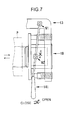
2006-321615 FIG. 7 , if an attachment member 91 (fulcrum) that couples thecradle 13 to thelever handle 141 is fixed, and an attachment member 92 (point of load) that connects thepackage driving section 18 to thelever handle 141 is fixed, variation in the distance between the fulcrum and the point of load cannot be accommodated. In such a structure, thecradle 13 cannot be opened or closed. - The structure of the attachment member 91 (fulcrum) of the
cradle 13 and thelever handle 141 and the attachment member 92 (point of load) of thepackage driving section 18 and thelever handle 141 therefore needs to be such that the variation in the distance between the fulcrum and the point of load can be accommodated. The middle portion of the lever handle disclosed in Japanese Patent Application Laid-open No.2006-321615 - In the structure disclosed in Japanese Patent Application Laid-open No.
2006-321615 - An example of a structure that can accommodate the variation in the distance between the fulcrum and the point of load of the lever handle is shown in
FIG. 8 . In this structure, the attachment member 91 (fulcrum) between thecradle 13 and thelever handle 141 is fixed, while aslot 93 and a stud (pin) 94, or the like are used as the attachment member 92 (point of load) between thepackage driving section 18 and thelever handle 141. This structure, however, allows movement of thelever handle 141 in its longitudinal direction at theattachment member 92. The play between theslot 93 and the stud (pin) 94 therefore becomes too large to control the vibration of thelever handle 141. Because the vibration of thepackage driving section 18 increases the vibration of thelever handle 141, the wearing of theattachment member 91, vibration of a tip portion of thelever handle 141, and the like tend to appear, which tends to lead to the damage of thelever handle 141. - It is an object of the present invention to provide a yarn winding device that can suppress vibration of a lever handle and avoid damage of the lever handle.
- A yarn winding device according to an aspect of the present invention includes a package driving section that directly drives and rotates a package; a cradle that supports the package driving section detachably from the package; a lever handle that is pivotally supported by the cradle and coupled to the package driving section, the package driving section being coupled to and decoupled from the package by pivoting the lever handle with respect to the cradle; and a first supporting member that couples the package driving section and the lever handle to each other, allows the lever handle only to pivot, and regulates movement of a pivotal center of the lever handle relative to the package driving section.
- The above and other objects, features, advantages and the technical and industrial significance of this invention will be better understood by reading the following detailed description of presently preferred embodiments of the invention, when considered in connection with the accompanying drawings.
-
-
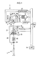
FIG. 1 is a simplified diagram of a yarn winding unit viewed from front, according to an embodiment of the present invention; -
FIG. 2 is a plan view of a winding section; -
FIG. 3 is a diagram showing the winding section viewed from a direction of an arrow A inFIG. 2 ; -
FIGS. 4A and 4B are cross-sectional views of a first supporting member sectioned along a line B-B inFIG. 2 ; -
FIGS. 5A and 5B are cross-sectional views of a second supporting member sectioned along a line C-C inFIG. 2 ; -
FIG. 6 is a diagram of a structure for mounting a lever handle onto a package driving section and a cradle; -
FIG. 7 is a diagram of another structure for mounting the lever handle onto the package driving section and the cradle; and -
FIG. 8 is a diagram of still another structure for mounting the lever handle onto the package driving section and the cradle. - Exemplary embodiments of a yarn winding unit 1 according to the present invention are explained below with reference to
FIGS. 1 to 5B . - The yarn winding unit 1 according to an embodiment, as shown in
FIG. 1 , forms layers of yarn on awinding tube 82 to form a package P while traversing a yarn Y supplied from ayarn supplying bobbin 81 by atraversing device 3. The yarn Y runs in a direction from theyarn supplying bobbin 81 to the package P. Although a single yarn winding unit 1 is depicted inFIG. 1 , a typical automatic winder includes multiple yarn winding units 1. The yarn winding unit 1 depicted inFIG. 1 forms a cone-shaped package P; the yarn winding unit 1, however, can be configured to form a cheese-shaped package or a package of any other shape. - In this specification, the
winding tube 82 and the package P may be collectively referred to as a winding bobbin B. The winding bobbin B without any yarn wound thereon is thewinding tube 82. The winding bobbin B with yarn wound thereon is the package P. - First, an overview of the yarn winding unit 1 is explained. As shown in
FIG. 1 , the yarn winding unit 1 includes a winding section (yarn winding device) 2, thetraversing device 3, and ayarn supplying section 4. - The
winding section 2 winds the yarn Y into the package P. As shown inFIGS. 1 and2 , thewinding section 2 includes acradle 13,bearings package driving section 18, alever handle 41, acontact roller 14, a winding bobbinrotational speed sensor 32, and a windingbobbin diameter sensor 33. Thecradle 13 is freely swingable around aswing shaft 15. Thecradle 13 supports thepackage driving section 18 detachably from the package P. By manipulating thelever handle 41 and opening and closing thecradle 13, the winding bobbin B (package P) can be mounted on and demounted from thecradle 13. Thebearings cradle 13 swings. With this arrangement, contact between the periphery of the winding bobbin B and thecontact roller 14 can be suitably maintained. As shown inFIG. 3 , adent 101 is formed in acasing 100 that supports thecradle 13 so that thecasing 100 is prevented from interfering with thepackage driving section 18 when thecradle 13 swings. - The
package driving section 18 directly drives and rotates the winding bobbin B (package P). A driving shaft of thepackage driving section 18 is coupled to the winding bobbin B in such a manner that, when thebearings cradle 13 hold the winding bobbin B, the driving shaft cannot rotate relative to the winding bobbin B (i.e., direct drive system). Thepackage driving section 18 actively drives and rotates the winding bobbin B to wind the yarn Y. - The winding bobbin
rotational speed sensor 32 detects a rotational speed (the number of rotations per unit time) of the winding bobbin B. The windingbobbin diameter sensor 33 detects a diameter of the winding bobbin B. The windingbobbin diameter sensor 33 is a rotary encoder, a resolver, or the like. The windingbobbin diameter sensor 33 detects a swinging angle of thecradle 13 and determines the diameter of the winding bobbin B based on the swinging angle. - The
contact roller 14 is a cylindrical roller that is driven to rotate in contact with the periphery of the winding bobbin B. Thecontact roller 14 presses the yarn Y against the surface of the winding bobbin B at a suitable pressure, and also suitably shapes the winding bobbin B (package P). Thecontact roller 14 can be a cylindrical roller or a cone-shaped roller with one end having a larger diameter and the other end having a smaller diameter. A roller rotation sensor 36 is arranged at one end of thecontact roller 14. - As shown in
FIGS. 1 and2 , thetraversing device 3 is arranged near the winding bobbin B (package P). Thetraversing device 3 is driven independently of the winding bobbin B, and traverses the yarn Y that is to be wound on the winding bobbin B. Thetraversing device 3 includes atraverse guide 17 and a traverseguide driving section 19. - The
traverse guide 17 is a hooking member that hooks the yarn Y and thereby traverses the yarn Y. Thetraverse guide 17 is arranged at a tip end of a swingable arm member. The traverseguide driving section 19 drives the arm member to reciprocate in a distance of a winding width of the winding bobbin B so that thetraverse guide 17 reciprocates. A servomotor is used as a motor of the traverseguide driving section 19 according to the present embodiment; however, a step motor or the like can be used instead. Thetraverse guide 17 can be shaped into a hooking member or into two rod-like members with their tip ends being open. - As shown in
FIG. 1 , theyarn supplying section 4 supplies the yarn Y that is to be wound on the winding bobbin B. Theyarn supplying bobbin 81 is set in theyarn supplying section 4. In a yarn running path between theyarn supplying section 4 and thecontact roller 14, atension applying device 20, ayarn joining device 21, and ayarn clearer 22 are arranged in this order from theyarn supplying section 4 side. Thetension applying device 20 applies a suitable tension to the yarn Y. A not-shown sensor outputs a signal representing a size of the yarn Y that passes through a detecting section, ananalyzer 23 processes the signal output from the sensor, and theyarn clearer 22 detects a yarn defect, such as a slub, based on the result of the processing at theanalyzer 23. In addition to a defect in the size of the yarn Y, theyarn clearer 22 can also detect any foreign object included in the yarn Y. A not-shown cutter is arranged in theyarn clearer 22 to cut the yarn Y when a yarn defect is detected (to make a clearer cut) and to discontinue the winding due to a traversing defect (to make an additional cut) even if no yarn defect is detected. Theyarn joining device 21 joins an end of a lower yarn on theyarn supplying bobbin 81 side and an end of an upper yarn on the winding bobbin B (package P) side when the yarn Y is cut by theyarn clearer 22 or when yarn supply from theyarn supplying bobbin 81 runs out. - A
suction pipe 24 is arranged below the yarn joining device 21 (on an upstream side in a yarn running direction) to serve as a lower yarn catching and guiding section that catches a yarn end on theyarn supplying bobbin 81 side by suction and guides the caught yarn end to theyarn joining device 21. Asuction mouth 27 is arranged above the yarn joining device 21 (on a downstream side in the yarn running direction) to serve as a yarn end catching section that catches a yarn end on the winding bobbin B side by suction and guides it to theyarn joining device 21. Thesuction pipe 24 is formed into a pipe and vertically pivots around ashaft 25. Thesuction pipe 24 has asuction vent 26 on its tip end. Thesuction mouth 27 is also formed into a pipe, and vertically pivots around ashaft 28. Amouth 29 is arranged at a tip end of thesuction mouth 27. A not-shown negative pressure source is connected to thesuction pipe 24 and thesuction mouth 27 so that suctioning is established in thesuction vent 26 and themouth 29 at the tip ends of thesuction pipe 24 and thesuction mouth 27, respectively. - A structure that controls the operation of the yarn winding unit 1 is now explained. According to the present embodiment, as shown in
FIG. 1 , thepackage driving section 18 that drives the winding bobbin B and the traverseguide driving section 19 that drives thetraverse guide 17 are separately and independently arranged. Driving of the winding bobbin B and thetraverse guide 17 is separately and independently controlled. Aunit controller 38 is arranged in each yarn winding unit 1 to control the yarn winding unit 1. Theunit controller 38 is connected to a windingbobbin driving controller 31 and atraverse controller 34. The windingbobbin driving controller 31 controls the driving and stopping of thepackage driving section 18, based on a control signal received from theunit controller 38. Thetraverse controller 34 controls the driving and stopping of the traverseguide driving section 19 based on the control signal received from theunit controller 38. - The winding bobbin
rotational speed sensor 32 transmits a rotational speed signal representing a detected rotational speed of the winding bobbin B to theunit controller 38, the windingbobbin driving controller 31, and thetraverse controller 34. The windingbobbin diameter sensor 33 transmits a diameter signal representing a detected diameter of the winding bobbin B to theunit controller 38. The diameter signal is transferred from theunit controller 38 to the windingbobbin driving controller 31 and thetraverse controller 34. - A signal (pulse signal) output from the roller rotation sensor 36, which is arranged at one end of the
contact roller 14, is input to a roller rotationalspeed detecting section 37. The roller rotationalspeed detecting section 37 detects a rotational speed (the number of rotations per unit time) of thecontact roller 14 based on this signal, and outputs a rotational speed signal representing a rotational speed of thecontact roller 14 to theunit controller 38. - The
unit controller 38 is connected to theyarn clearer 22, theyarn joining device 21, thesuction pipe 24, and thesuction mouth 27 that serves as the yarn end catching section. Because the yarn Y needs to be cut off when the winding is suspended due to presence of a yarn defect or due to a traverse defect although no yarn defect is detected, theunit controller 38 controls the yarn cutting operation of theyarn clearer 22. Theunit controller 38 further controls a yarn joining operation of theyarn joining device 21 in which the yarn end on theyarn supplying bobbin 81 side and the yarn end on the winding bobbin B side are joined together when the yarn Y is cut by theyarn clearer 22 or when the yarn supply from theyarn supplying bobbin 81 runs out. Theunit controller 38 also controls yarn end catching operations performed by thesuction pipe 24 and thesuction mouth 27 and a guiding operation of guiding the yarn ends to theyarn joining device 21. - The
unit controller 38 is connected to amain controller 39. Themain controller 39 centrally controls the multiple yarn winding units 1 included in the automatic winder. Theunit controller 38, the roller rotationalspeed detecting section 37, themain controller 39, the windingbobbin driving controller 31, and thetraverse controller 34 each include a central processing unit (CPU) as a calculating unit, and a read-only memory (ROM), a random-access memory (RAM), and the like as a storing unit. The ROMs store therein a controlling software program that causes hardware such as the CPU to operate as a controlling unit. - The lever handle 41 and a structure to mount the lever handle 41 are explained below.
- First, the
package driving section 18 onto which the lever handle 41 is mounted and a mounting structure for mounting thepackage driving section 18 onto thecradle 13 are explained. Thepackage driving section 18 and the mounting structure for mounting thepackage driving section 18 onto thecradle 13 are basically the same as the mounting structure disclosed in Japanese Patent Application Laid-open No.2006-321615 - As shown in
FIGS. 2 and3 , thepackage driving section 18 includes apackage driving motor 51 arranged inside ahousing 50. Thebearing 52 is mounted on the driving shaft of thepackage driving motor 51. Abackup flange 55 is attached to thehousing 50 on itsbearing 52 side. - The
package driving section 18 is coupled to thecradle 13. An invertedU-shaped member 47 is formed in thecradle 13 in such a manner as to straddle thepackage driving section 18. Two end portions of the invertedU-shaped member 47 are arranged at the two end portions of thepackage driving section 18 when viewed from the side in a direction substantially parallel to the driving shaft of thepackage driving section 18. A pair ofcylindrical bodies 56 is arranged parallel to a driving shaft line of thepackage driving motor 51 in the two end portions of the invertedU-shaped member 47. A guidingrod 57 is engaged slidably with each of these twocylindrical bodies 56. One end of each guidingrod 57 is fixed to thebackup flange 55. An urgingspring 58 is arranged inside eachcylindrical body 56. The urgingspring 58 urges, via the guidingrod 57, thebackup flange 55 and also theentire housing 50 towards the bearing 53 on the other end of the cradle 13 (seeFIG. 1 ), and exerts holding force to hold the winding bobbin B between thebearings cradle 13 to regulate the movement of thehousing 50 so that the movement of thepackage driving section 18 is maintained under a certain amount. - The lever handle 41 is manipulated when opening and closing the
cradle 13 by coupling and decoupling thepackage driving section 18 to and from the winding bobbin B (package P). As shown inFIGS. 2 and3 , the lever handle 41 includes amain shaft portion 42 and agrip portion 43. Themain shaft portion 42 is the main body of thelever handle 41. Themain shaft portion 42 includes afirst shaft member 44 and a second shaft member 45 (seeFIGS. 4A and 4B ). Thefirst shaft member 44 and thesecond shaft member 45 are both screwed into, and thereby connected to, anattachment member 62 of a first supportingmember 61, which is explained later, to form themain shaft portion 42. Thegrip portion 43 is a portion that an operator grips to manipulate the lever handle 41 to open or close thecradle 13. Thegrip portion 43 is attached to one end of themain shaft portion 42. - The lever handle 41 is arranged across the
cradle 13 and thepackage driving section 18. The lever handle 41 is coupled to thepackage driving section 18 by the first supportingmember 61. The lever handle 41 is coupled to thecradle 13 by a second supportingmember 71. - The first supporting
member 61 couples the lever handle 41 to thepackage driving section 18. The first supportingmember 61 allows the lever handle 41 only to pivot, and also regulates the movement of a pivotal center of the lever handle 41 relative to thepackage driving section 18. As shown inFIG. 4A , the first supportingmember 61 includes theattachment member 62, abolt 64, acollar 65, abush 66,vibration absorbing members 67, andwashers 68. A first fixingportion 54 is formed in thehousing 50 of thepackage driving section 18 to fix the first supportingmember 61. Thebolt 64 serves as a pivotal shaft that pivotally supports thelever handle 41. - The
attachment member 62 serves as a bearing that supports thebolt 64, which serves as the pivotal shaft, via thecollar 65. As mentioned earlier, theattachment member 62 connects thefirst shaft member 44 and thesecond shaft member 45 of the lever handle 41 to each other. Ahole 63 is formed in theattachment member 62 to insert thebolt 64 or the like. - The
bolt 64, with thecollar 65 and thebush 66 attached, is inserted into thehole 63 of theattachment member 62. Thebush 66 is a lubricating member that allows the lever handle 41 to smoothly pivot. Thecollar 65 is a metallic cylindrical member that prevents a direct contact of a screw portion of thebolt 64 with thebush 66. Thecollar 65 controls tightness of thebolt 64 to allow the lever handle 41 to smoothly pivot. - The
vibration absorbing members 67 are interposed above and below thehole 63 of theattachment member 62, or in other words, between theattachment member 62 and thebolt 64 and between theattachment member 62 and the first fixingportion 54. Thevibration absorbing members 67 are preferably made of an elastic material. According to the present embodiment, thevibration absorbing members 67 are made of urethane rubber. However, the material of thevibration absorbing members 67 is not limited to urethane rubber, and any other material that can absorb vibration can be used. Thewashers 68 are interposed between thevibration absorbing member 67 and thebolt 64 and between thevibration absorbing member 67 and the first fixingportion 54. - The first supporting
member 61 is mounted on the first fixingportion 54 by screwing thebolt 64 into the first fixingportion 54. The lever handle 41 is mounted on thepackage driving section 18 by tightening thebolt 64. The lever handle 41 is allowed only to pivot with respect to thepackage driving section 18. The movement of the pivotal center (bolt 64) of the lever handle 41 is not regulated with respect to thepackage driving section 18. - In the above description, a structure employing the
bolt 64 has been explained. Astud 69, for example, can be used in place of thebolt 64, as shown inFIG. 4B . Because a cylindrical portion of thestud 69 does not include a screwing portion, thecollar 65 can be omitted. In such a case, as shown inFIG. 4B , thebush 66 can be inserted directly into thestud 69, thereby reducing the number of components. - The second supporting
member 71 couples the lever handle 41 to thecradle 13. The second supportingmember 71 allows the lever handle 41 to pivot with respect to thecradle 13 and also to move in a longitudinal direction of thelever handle 41. As shown inFIG. 5A , the second supportingmember 71 includes aretainer 72, abolt 74, acollar 75, aflanged bush 76, andwashers 78. Asecond fixing portion 48 is formed in thecradle 13 to fix the second supportingmember 71. Thebolt 74 serves as a slide shaft that slidably supports thelever handle 41. - The
retainer 72 holds thebolt 74, which serves as the slide shaft, via thecollar 75 and the like. A retaininggroove 73 is formed in theretainer 72 to hold thebolt 74 and the like. - The
bolt 74 to which thecollar 75 and theflanged bush 76 are attached is held by the retaininggroove 73 of theretainer 72. Theflanged bush 76 is a lubricating member that allows the lever handle 41 to smoothly slide. Thecollar 75 is a metallic cylindrical member that prevents the screwing portion of thebolt 74 from being in a direct contact with theflanged bush 76. Thecollar 75 controls tightness of thebolt 74 and allows the lever handle 41 to smoothly slide. Thewashers 78 are interposed between theflanged bush 76 and thebolt 74 and between theflanged bush 76 and the second fixingportion 48. - The second supporting
member 71 is attached to the second fixingportion 48 by screwing thebolt 74 into the second fixingportion 48. The lever handle 41 is attached to thecradle 13 by tightening thebolt 74. The lever handle 41 is allowed to pivot with respect to thecradle 13 and also to move in the longitudinal direction of thelever handle 41. - In the above description, a structure employing the
bolt 74 has been explained. However, astud 79, for example, can be used in place of thebolt 74, as shown inFIG. 5B . Because a cylindrical portion of thestud 79 does not have a screwing portion, thecollar 75 can be omitted. In such a case, as shown inFIG. 5B , thestud 79 can be inserted directly into theflanged bush 76, thereby reducing the number of components. - In the above structure, when mounting the winding bobbin B (winding tube 82) onto the
bearings grip portion 43 of the lever handle 41 in an opening direction, as shown inFIG. 2 . The first supportingmember 61 allows only pivoting of thelever handle 41, but regulates the movement of the pivotal center of the lever handle 41 with respect to thepackage driving section 18. The second supportingmember 71 allows both pivoting of the lever handle 41 with respect to thecradle 13 and the movement of the lever handle 41 in its longitudinal direction. Consequently, the variation in the distance between the first supporting member 61 (point of load) and the second supporting member 71 (fulcrum) is accommodated, and the pivoting of the lever handle 41 can thereby be smoothly performed. - When the lever handle 41 is turned in the opening direction, the
entire housing 50 is pulled by thelever handle 41. Consequently, thehousing 50, thepackage driving motor 51, and thebearing 52 are moved in a direction away from the bearing 53 on the other side against the force of the urgingspring 58. A movement direction of thehousing 50, thepackage driving motor 51, and thebearing 52 is brought into a direction parallel to the shaft direction of the winding bobbin B by guiding of thecylindrical body 56 and the guidingrod 57. - With the distance between the
bearings bearings FIG. 2 to the original position. Thehousing 50, thepackage driving motor 51, and thebearing 52 are thereby moved toward the bearing 53 of the other side, in the direction parallel to the axial line of the winding bobbin B by the force of the urgingspring 58 so that the winding bobbin B can be rotatably held at its two ends by thebearings - When the manipulation of the lever handle 41 is performed, the guiding
rod 57 is slid with respect to thecylindrical body 56. At this time, air comes in and out of thecylindrical body 56. More specifically, when the guidingrod 57 is elongated with respect to thecylindrical body 56, air is sucked into thecylindrical body 56 through clearance between thecylindrical body 56 and the sliding portion of the guidingrod 57. When the guidingrod 57 is contracted with respect to thecylindrical body 56, air comes out of thecylindrical body 56 through the clearance between thecylindrical body 56 and the sliding portion of the guidingrod 57. Because cotton fly and/or fiber waste, which exist in the air around the yarn winding unit 1, are accumulated in the clearance between thecylindrical body 56 and the sliding portion of the guidingrod 57, slidability between thecylindrical body 56 and the guidingrod 57 tends to gradually reduce. - For this reason, a
vent hole 59 is formed in a bottom portion of the cylindrical body 56 (on the end surface opposite the surface on which thebackup flange 55 is arranged), and a sponge filter (not shown) is arranged in thevent hole 59. When the guidingrod 57 is slid with respect to thecylindrical body 56, air comes in and out through thevent hole 59, and therefore the amount of air coming in and out through the clearance of the sliding portion decreases. With the filter arranged in thevent hole 59, the cotton fly and/or the fiber waste are prevented from entering the inside of thecylindrical body 56. Therefore, cotton fly and/or the fiber waste do not accumulate in the clearance of the sliding portion, and excellent slidability can be maintained between thecylindrical body 56 and the guidingrod 57. - During the operation of the yarn winding unit 1, the
package driving motor 51 of thepackage driving section 18 is driven, and vibration produced by the driving is conducted to the lever handle 41 via thehousing 50. The first supportingmember 61, however, that is arranged near the vibration-producingpackage driving section 18 allows the lever handle 41 only to pivot, while the first supportingmember 61 regulates the movement of the pivotal center of the lever handle 41 with respect to thepackage driving section 18. With small play provided between thepackage driving section 18 and thelever handle 41, the movement of the lever handle 41 can be regulated. The lever handle 41 can therefore be prevented from vibrating even when the vibration is conducted from thepackage driving section 18. - The
vibration absorbing members 67 are interposed between thehousing 50 of thepackage driving section 18 and the first supportingmember 61 that is the attachment member of thelever handle 41. Because the vibration from thepackage driving section 18 is absorbed by thevibration absorbing members 67, the vibration is not conducted to thelever handle 41. - The yarn winding unit 1 according to the present embodiment explained above yields the following effects.
- The lever handle 41 that opens and closes the
cradle 13 is coupled to thepackage driving section 18 by the first supportingmember 61. The first supportingmember 61 allows the lever handle 41 only to pivot, and regulates the movement of the pivotal center of the lever handle 41 with respect to thepackage driving section 18. Because of this first supportingmember 61, the play between thepackage driving section 18 and the lever handle 41 can be set small, the vibration of the lever handle 41 can be suppressed, and damage of the lever handle 41 can be prevented. - The lever handle 41 that opens and closes the
cradle 13 is coupled to thecradle 13 by the second supportingmember 71. The second supportingmember 71 allows the lever handle 41 to pivot with respect to thecradle 13 and also to move in the longitudinal direction of thelever handle 41. With this arrangement, the variation in the distance between the fulcrum and the point of load of the leverage in accordance with arc pivoting of thelever handle 41 and parallel movement of thepackage driving section 18 can be absorbed, and thecradle 13 can be opened and closed smoothly. - The second supporting
member 71 includes thebolt 74 that is the slide shaft and theretainer 72 that holds thebolt 74. Consequently, the structure of the second supportingmember 71 can be simplified. - The first supporting
member 61 includes thebolt 64 that is the pivotal shaft that pivotally supports thelever handle 41 and theattachment member 62 that is the bearing that supports thebolt 64. Thevibration absorbing members 67 are arranged between thebolt 64 and theattachment member 62. With this arrangement, the vibration of thepackage driving section 18 can be absorbed, and the vibration of the lever handle 41 can be suppressed. - Because the
vibration absorbing member 67 is an elastic body, the vibration of thepackage driving section 18 can be effectively absorbed, and the vibration of the lever handle 41 can be suppressed. - The
casing 100 on which thecradle 13 is mounted has thedent 101 to prevent thecasing 100 from interfering with thepackage driving section 18. In the yarn winding unit 1 of the direct drive system that directly drives and rotates the package P, thepackage driving section 18 tends to interfere with thecasing 100 when the windingtube 82 has a small diameter. Because thedent 101 is formed in thecasing 100 to prevent thecasing 100 from interfering with thepackage driving section 18, the interference between thepackage driving section 18 and thecasing 100 can be prevented, and the vibration of thecasing 100 and the lever handle 41 can be suppressed. - Various embodiments of the present invention have been explained above; however, various modifications can be made to those embodiments. For example, the structure for controlling the operation of the yarn winding unit 1 is not limited to that explained in the above embodiments. For example, the winding
bobbin driving controller 31 and thetraverse controller 34 can be arranged in theunit controller 38. - In the above embodiments, in the
traversing device 3, the longitudinal direction of the arm member is parallel to an installation direction of the yarn winding unit 1 (vertical direction). However, the longitudinal direction of the arm member can be perpendicular to an installation surface of the yarn winding unit 1. Thetraversing device 3 drives and reciprocates the arm member by the traverseguide driving section 19. An endless timing belt can be arranged near thecontact roller 14, and thetraverse guide 17 can be attached to this timing belt. The timing belt can be driven and reciprocated by, for example, a pulse motor. - In the above explanation, the manipulation of the
cradle 13 is performed by the operator, but can be performed by a doffing carrier cart. When the package P is fully wound at the yarn winding unit 1, the doffing carrier cart performs a doffing operation to remove the fully wound package P from thecradle 13. - In the above embodiments, the diameter of the winding bobbin B is detected by the winding
bobbin diameter sensor 33. However, any other structure in which the diameter of the winding bobbin B can be detected can be employed. For example, the diameter of the winding bobbin B can be calculated by measuring the amount of the yarn Y that is wound on the winding bobbin B. - According to the present embodiment, an example in which the present invention is applied to the automatic winder has been explained; however, the present invention is applicable to other yarn winding units such as spinning machines.
- The configuration of each component is not limited to the one that is shown in the drawings. For example, steps can be formed in the
stud 69 shown inFIG. 4B and thestud 79 shown inFIG. 5B in their longitudinal direction to form a tightening portion. - A yarn winding device according to an aspect of the present invention includes a package driving section, a cradle, a lever handle, and a first supporting member. The package driving section directly drives and rotates a package. The cradle supports the package driving section detachably from the package. The lever handle is pivotally supported by the cradle and coupled to the package driving section. By pivoting the lever handle with respect to the cradle, the package driving section is coupled to and decoupled from the package. The first supporting member couples the package driving section and the lever handle to each other, allows the lever handle only to pivot, and regulates movement of a pivotal center of the lever handle relative to the package driving section.
- With the first supporting member, play between the package driving section and the lever handle can be set small, and vibration of the lever handle can be suppressed, while damage of the lever handle can be prevented.
- The yarn winding device according to another aspect of the present invention further includes a second supporting member. The second supporting member couples the lever handle to the cradle and allows the lever handle to pivot with respect to the cradle and to move in a longitudinal direction of the lever handle. With this arrangement, both arc pivoting of the lever handle and variation in a distance between a fulcrum and a point of load in accordance with parallel movement of the package driving section can be accommodated, and thereby the cradle can be smoothly opened and closed.
- The second supporting member preferably includes a slide shaft and a retainer that holds the slide shaft. With this arrangement, the structure of the second supporting member can be simplified.
- The first supporting member preferably includes a pivotal shaft, a bearing, and a vibration absorbing member. The pivotal shaft pivotally supports the lever handle. The bearing supports the pivotal shaft. The vibration absorbing member is arranged between the pivotal shaft and the bearing. With this arrangement, the vibration of the package driving section can be absorbed and the vibration of the lever handle can be suppressed.
- The vibration absorbing member is preferably an elastic body. The vibration absorbing member can effectively absorb the vibration of the package driving section and suppress the vibration of the lever handle.
- The yarn winding device preferably includes a casing. The cradle is mounted on the casing. A dent is formed in the casing to prevent interference with the package driving section. In the yarn winding unit of a direct drive system, which directly drives and rotates the package, the package driving section tends to interfere with the casing if a winding tube has a small diameter. Because the dent is formed in the casing to prevent the interference with the package driving section, the package driving section is prevented from interfering with the casing, and the vibration of the casing and the lever handle can be suppressed.
- Although the invention has been described with respect to specific embodiments for a complete and clear disclosure, the appended claims are not to be thus limited but are to be construed as embodying all modifications and alternative constructions that may occur to one skilled in the art that fairly fall within the scope of the claims.
Claims (6)
- A yarn winding device comprising:a package driving section (18) adapted to directly drive and rotate a package (P);a cradle (13) adapted to support the package driving section (18) detachably from the package (P);a lever handle (41) that is pivotally supported by the cradle (13) and coupled to the package driving section (18), the package driving section (18) being adapted to be coupled to and decoupled from the package (P) by pivoting the lever handle (41) with respect to the cradle (13); characterized bya first supporting member (61) adapted to couple the package driving section (18) and the lever handle (41) to each other, adapted to allow the lever handle (41) only to pivot, and adapted to regulate movement of a pivotal center of the lever handle (41) relative to the package driving section (18).
- The yarn winding device according to Claim 1, characterized by a second supporting member (71) adapted to couple the lever handle (41) to the cradle (13) and adapted to allow the lever handle (41) to pivot with respect to the cradle (13) and to move in a longitudinal direction of the lever handle (41).
- The yarn winding device according to Claim 2, characterized in that the second supporting member (71) includes a slide shaft (74) and a retainer (72) adapted to retain the slide shaft (74).
- The yarn winding device according to any one of Claims 1 to 3, characterized in that the first supporting member (61) includes a pivotal shaft (64) adapted to pivotally support the lever handle (41), a bearing (62) adapted to support the pivotal shaft (64), and a vibration absorbing member (67) that is arranged between the pivotal shaft (64) and the bearing (62).
- The yarn winding device according to Claim 4, characterized in that the vibration absorbing member (67) is an elastic body.
- The yarn winding device according to any one of Claims 1 to 5, further comprising a casing (100) on which the cradle (13) is mounted, characterized in that
a dent (101) is formed in the casing (100) and adapted to prevent interference with the package driving section (18).
Applications Claiming Priority (1)
| Application Number | Priority Date | Filing Date | Title |
|---|---|---|---|
| JP2011206543A JP2013067478A (en) | 2011-09-21 | 2011-09-21 | Yarn winding unit |
Publications (3)
| Publication Number | Publication Date |
|---|---|
| EP2573016A2 true EP2573016A2 (en) | 2013-03-27 |
| EP2573016A3 EP2573016A3 (en) | 2014-03-26 |
| EP2573016B1 EP2573016B1 (en) | 2014-10-01 |
Family
ID=46727129
Family Applications (1)
| Application Number | Title | Priority Date | Filing Date |
|---|---|---|---|
| EP20120181932 Active EP2573016B1 (en) | 2011-09-21 | 2012-08-28 | Yarn winding device |
Country Status (3)
| Country | Link |
|---|---|
| EP (1) | EP2573016B1 (en) |
| JP (1) | JP2013067478A (en) |
| CN (1) | CN103010831B (en) |
Cited By (4)
| Publication number | Priority date | Publication date | Assignee | Title |
|---|---|---|---|---|
| WO2015055399A3 (en) * | 2013-10-14 | 2015-06-18 | Oerlikon Textile Gmbh & Co. Kg | Device for extruding, stretching, and winding a group of film strips |
| CN110577105A (en) * | 2019-10-09 | 2019-12-17 | 江先庆 | A transport rack suitable for wire and cable production |
| CN112193935A (en) * | 2020-10-28 | 2021-01-08 | 荀新平 | Spool distance adjusting device that can be used to multiple diameter spool rolling |
| CN112693959A (en) * | 2020-12-29 | 2021-04-23 | 周吉娟 | Winding machine for producing chemical fibers |
Families Citing this family (4)
| Publication number | Priority date | Publication date | Assignee | Title |
|---|---|---|---|---|
| JP2016147738A (en) | 2015-02-12 | 2016-08-18 | 村田機械株式会社 | Yarn winding machine |
| CN107973182A (en) * | 2017-12-19 | 2018-05-01 | 江苏华灵纺机有限公司 | Bobbin coiling transmission device and its control method |
| CN113697583A (en) * | 2021-09-13 | 2021-11-26 | 际华三五四三针织服饰有限公司 | External-supporting 82 type triangular towel folding machine |
| CN115258812A (en) * | 2022-08-10 | 2022-11-01 | 邵阳连泰鞋业有限公司 | Automatic shoe lace winding machine |
Citations (1)
| Publication number | Priority date | Publication date | Assignee | Title |
|---|---|---|---|---|
| JP2006321615A (en) | 2005-05-19 | 2006-11-30 | Murata Mach Ltd | Thread winding device, and textile machine provided with the same |
Family Cites Families (4)
| Publication number | Priority date | Publication date | Assignee | Title |
|---|---|---|---|---|
| JP2982733B2 (en) * | 1997-02-26 | 1999-11-29 | 村田機械株式会社 | Winding control device of spinning winder |
| DE19908093A1 (en) * | 1999-02-25 | 2000-08-31 | Schlafhorst & Co W | Bobbin drive at a cross wound bobbin winding frame has an integrated pneumatic brake unit to move the stator housing with a brake lining against a braking surface on the rear of the bobbin holder plate |
| DE10040106A1 (en) * | 2000-08-17 | 2002-02-28 | Schlafhorst & Co W | Winding device for a textile machine producing cross-wound bobbins |
| JP2011144028A (en) * | 2010-01-15 | 2011-07-28 | Murata Machinery Ltd | Yarn winding machine and yarn guiding method |
-
2011
- 2011-09-21 JP JP2011206543A patent/JP2013067478A/en not_active Withdrawn
-
2012
- 2012-08-23 CN CN201210303466.XA patent/CN103010831B/en active Active
- 2012-08-28 EP EP20120181932 patent/EP2573016B1/en active Active
Patent Citations (1)
| Publication number | Priority date | Publication date | Assignee | Title |
|---|---|---|---|---|
| JP2006321615A (en) | 2005-05-19 | 2006-11-30 | Murata Mach Ltd | Thread winding device, and textile machine provided with the same |
Cited By (5)
| Publication number | Priority date | Publication date | Assignee | Title |
|---|---|---|---|---|
| WO2015055399A3 (en) * | 2013-10-14 | 2015-06-18 | Oerlikon Textile Gmbh & Co. Kg | Device for extruding, stretching, and winding a group of film strips |
| US10730716B2 (en) | 2013-10-14 | 2020-08-04 | Oerlikon Textile Gmbh & Co. Kg | Device for extruding, stretching, and winding a group of film strips |
| CN110577105A (en) * | 2019-10-09 | 2019-12-17 | 江先庆 | A transport rack suitable for wire and cable production |
| CN112193935A (en) * | 2020-10-28 | 2021-01-08 | 荀新平 | Spool distance adjusting device that can be used to multiple diameter spool rolling |
| CN112693959A (en) * | 2020-12-29 | 2021-04-23 | 周吉娟 | Winding machine for producing chemical fibers |
Also Published As
| Publication number | Publication date |
|---|---|
| CN103010831A (en) | 2013-04-03 |
| JP2013067478A (en) | 2013-04-18 |
| CN103010831B (en) | 2016-08-10 |
| EP2573016A3 (en) | 2014-03-26 |
| EP2573016B1 (en) | 2014-10-01 |
Similar Documents
| Publication | Publication Date | Title |
|---|---|---|
| EP2573016B1 (en) | Yarn winding device | |
| EP2169096B9 (en) | Spinning machine | |
| EP2157039B1 (en) | Textile machine | |
| EP2905249B1 (en) | Bobbin setting device and yarn winding machine | |
| EP2441718B1 (en) | Yarn winding apparatus | |
| CN104418162B (en) | Fiber is mechanical | |
| JP2012086923A (en) | Doffer and yarn winding machine including the same | |
| EP2484620A1 (en) | Yarn winder | |
| JP5915219B2 (en) | Yarn winding device | |
| EP3524556A1 (en) | Air spinning machine and air spinning method | |
| EP2907780A1 (en) | Bobbin setting device and yarn winding machine | |
| JP2014125349A (en) | Yarn storage apparatus and spinning unit | |
| JP5365697B2 (en) | Yarn winding device | |
| CN102992100B (en) | Reel cage, winding unit and Yarn winding machine | |
| JP2006306588A (en) | Yarn sag removing device in textile machine | |
| JP2013035664A (en) | Yarn winding device and yarn winding method | |
| EP2028149B1 (en) | Winding tension control device | |
| CN105883482B (en) | Bobbin supporting device and yarn winding machine | |
| EP2669229B1 (en) | Package discharging device and yarn winding machine | |
| EP2441719B1 (en) | Bobbin installation device and yarn winding apparatus including the same | |
| EP2853510B1 (en) | Service vehicle of textile machine | |
| JP2013056766A (en) | Doffing device, and textile machine including the same | |
| JP2017088344A (en) | Tension application device and yarn winding apparatus | |
| EP2862825B1 (en) | Winding device and yarn winding machine including the same | |
| EP2573229B1 (en) | Draft device and spinning machine |
Legal Events
| Date | Code | Title | Description |
|---|---|---|---|
| PUAI | Public reference made under article 153(3) epc to a published international application that has entered the european phase |
Free format text: ORIGINAL CODE: 0009012 |
|
| AK | Designated contracting states |
Kind code of ref document: A2 Designated state(s): AL AT BE BG CH CY CZ DE DK EE ES FI FR GB GR HR HU IE IS IT LI LT LU LV MC MK MT NL NO PL PT RO RS SE SI SK SM TR |
|
| AX | Request for extension of the european patent |
Extension state: BA ME |
|
| REG | Reference to a national code |
Ref country code: DE Ref legal event code: R079 Ref document number: 602012003238 Country of ref document: DE Free format text: PREVIOUS MAIN CLASS: B65H0049020000 Ipc: B65H0054553000 |
|
| PUAL | Search report despatched |
Free format text: ORIGINAL CODE: 0009013 |
|
| AK | Designated contracting states |
Kind code of ref document: A3 Designated state(s): AL AT BE BG CH CY CZ DE DK EE ES FI FR GB GR HR HU IE IS IT LI LT LU LV MC MK MT NL NO PL PT RO RS SE SI SK SM TR |
|
| AX | Request for extension of the european patent |
Extension state: BA ME |
|
| RIC1 | Information provided on ipc code assigned before grant |
Ipc: B65H 54/553 20060101AFI20140218BHEP Ipc: B65H 54/44 20060101ALI20140218BHEP |
|
| 17P | Request for examination filed |
Effective date: 20140305 |
|
| RBV | Designated contracting states (corrected) |
Designated state(s): AL AT BE BG CH CY CZ DE DK EE ES FI FR GB GR HR HU IE IS IT LI LT LU LV MC MK MT NL NO PL PT RO RS SE SI SK SM TR |
|
| GRAP | Despatch of communication of intention to grant a patent |
Free format text: ORIGINAL CODE: EPIDOSNIGR1 |
|
| INTG | Intention to grant announced |
Effective date: 20140519 |
|
| GRAS | Grant fee paid |
Free format text: ORIGINAL CODE: EPIDOSNIGR3 |
|
| GRAA | (expected) grant |
Free format text: ORIGINAL CODE: 0009210 |
|
| AK | Designated contracting states |
Kind code of ref document: B1 Designated state(s): AL AT BE BG CH CY CZ DE DK EE ES FI FR GB GR HR HU IE IS IT LI LT LU LV MC MK MT NL NO PL PT RO RS SE SI SK SM TR |
|
| REG | Reference to a national code |
Ref country code: GB Ref legal event code: FG4D |
|
| REG | Reference to a national code |
Ref country code: AT Ref legal event code: REF Ref document number: 689411 Country of ref document: AT Kind code of ref document: T Effective date: 20141015 Ref country code: CH Ref legal event code: EP |
|
| REG | Reference to a national code |
Ref country code: IE Ref legal event code: FG4D |
|
| REG | Reference to a national code |
Ref country code: DE Ref legal event code: R096 Ref document number: 602012003238 Country of ref document: DE Effective date: 20141113 |
|
| REG | Reference to a national code |
Ref country code: NL Ref legal event code: VDEP Effective date: 20141001 |
|
| REG | Reference to a national code |
Ref country code: AT Ref legal event code: MK05 Ref document number: 689411 Country of ref document: AT Kind code of ref document: T Effective date: 20141001 |
|
| REG | Reference to a national code |
Ref country code: LT Ref legal event code: MG4D |
|
| PG25 | Lapsed in a contracting state [announced via postgrant information from national office to epo] |
Ref country code: NL Free format text: LAPSE BECAUSE OF FAILURE TO SUBMIT A TRANSLATION OF THE DESCRIPTION OR TO PAY THE FEE WITHIN THE PRESCRIBED TIME-LIMIT Effective date: 20141001 |
|
| PG25 | Lapsed in a contracting state [announced via postgrant information from national office to epo] |
Ref country code: LT Free format text: LAPSE BECAUSE OF FAILURE TO SUBMIT A TRANSLATION OF THE DESCRIPTION OR TO PAY THE FEE WITHIN THE PRESCRIBED TIME-LIMIT Effective date: 20141001 Ref country code: NO Free format text: LAPSE BECAUSE OF FAILURE TO SUBMIT A TRANSLATION OF THE DESCRIPTION OR TO PAY THE FEE WITHIN THE PRESCRIBED TIME-LIMIT Effective date: 20150101 Ref country code: IS Free format text: LAPSE BECAUSE OF FAILURE TO SUBMIT A TRANSLATION OF THE DESCRIPTION OR TO PAY THE FEE WITHIN THE PRESCRIBED TIME-LIMIT Effective date: 20150201 Ref country code: ES Free format text: LAPSE BECAUSE OF FAILURE TO SUBMIT A TRANSLATION OF THE DESCRIPTION OR TO PAY THE FEE WITHIN THE PRESCRIBED TIME-LIMIT Effective date: 20141001 Ref country code: FI Free format text: LAPSE BECAUSE OF FAILURE TO SUBMIT A TRANSLATION OF THE DESCRIPTION OR TO PAY THE FEE WITHIN THE PRESCRIBED TIME-LIMIT Effective date: 20141001 Ref country code: CZ Free format text: LAPSE BECAUSE OF FAILURE TO SUBMIT A TRANSLATION OF THE DESCRIPTION OR TO PAY THE FEE WITHIN THE PRESCRIBED TIME-LIMIT Effective date: 20141001 Ref country code: PT Free format text: LAPSE BECAUSE OF FAILURE TO SUBMIT A TRANSLATION OF THE DESCRIPTION OR TO PAY THE FEE WITHIN THE PRESCRIBED TIME-LIMIT Effective date: 20150202 |
|
| PG25 | Lapsed in a contracting state [announced via postgrant information from national office to epo] |
Ref country code: SE Free format text: LAPSE BECAUSE OF FAILURE TO SUBMIT A TRANSLATION OF THE DESCRIPTION OR TO PAY THE FEE WITHIN THE PRESCRIBED TIME-LIMIT Effective date: 20141001 Ref country code: CY Free format text: LAPSE BECAUSE OF FAILURE TO SUBMIT A TRANSLATION OF THE DESCRIPTION OR TO PAY THE FEE WITHIN THE PRESCRIBED TIME-LIMIT Effective date: 20141001 Ref country code: HR Free format text: LAPSE BECAUSE OF FAILURE TO SUBMIT A TRANSLATION OF THE DESCRIPTION OR TO PAY THE FEE WITHIN THE PRESCRIBED TIME-LIMIT Effective date: 20141001 Ref country code: LV Free format text: LAPSE BECAUSE OF FAILURE TO SUBMIT A TRANSLATION OF THE DESCRIPTION OR TO PAY THE FEE WITHIN THE PRESCRIBED TIME-LIMIT Effective date: 20141001 Ref country code: GR Free format text: LAPSE BECAUSE OF FAILURE TO SUBMIT A TRANSLATION OF THE DESCRIPTION OR TO PAY THE FEE WITHIN THE PRESCRIBED TIME-LIMIT Effective date: 20150102 Ref country code: PL Free format text: LAPSE BECAUSE OF FAILURE TO SUBMIT A TRANSLATION OF THE DESCRIPTION OR TO PAY THE FEE WITHIN THE PRESCRIBED TIME-LIMIT Effective date: 20141001 Ref country code: RS Free format text: LAPSE BECAUSE OF FAILURE TO SUBMIT A TRANSLATION OF THE DESCRIPTION OR TO PAY THE FEE WITHIN THE PRESCRIBED TIME-LIMIT Effective date: 20141001 Ref country code: AT Free format text: LAPSE BECAUSE OF FAILURE TO SUBMIT A TRANSLATION OF THE DESCRIPTION OR TO PAY THE FEE WITHIN THE PRESCRIBED TIME-LIMIT Effective date: 20141001 |
|
| REG | Reference to a national code |
Ref country code: DE Ref legal event code: R097 Ref document number: 602012003238 Country of ref document: DE |
|
| PG25 | Lapsed in a contracting state [announced via postgrant information from national office to epo] |
Ref country code: SK Free format text: LAPSE BECAUSE OF FAILURE TO SUBMIT A TRANSLATION OF THE DESCRIPTION OR TO PAY THE FEE WITHIN THE PRESCRIBED TIME-LIMIT Effective date: 20141001 Ref country code: EE Free format text: LAPSE BECAUSE OF FAILURE TO SUBMIT A TRANSLATION OF THE DESCRIPTION OR TO PAY THE FEE WITHIN THE PRESCRIBED TIME-LIMIT Effective date: 20141001 Ref country code: DK Free format text: LAPSE BECAUSE OF FAILURE TO SUBMIT A TRANSLATION OF THE DESCRIPTION OR TO PAY THE FEE WITHIN THE PRESCRIBED TIME-LIMIT Effective date: 20141001 Ref country code: RO Free format text: LAPSE BECAUSE OF FAILURE TO SUBMIT A TRANSLATION OF THE DESCRIPTION OR TO PAY THE FEE WITHIN THE PRESCRIBED TIME-LIMIT Effective date: 20141001 |
|
| PLBE | No opposition filed within time limit |
Free format text: ORIGINAL CODE: 0009261 |
|
| STAA | Information on the status of an ep patent application or granted ep patent |
Free format text: STATUS: NO OPPOSITION FILED WITHIN TIME LIMIT |
|
| 26N | No opposition filed |
Effective date: 20150702 |
|
| PG25 | Lapsed in a contracting state [announced via postgrant information from national office to epo] |
Ref country code: SI Free format text: LAPSE BECAUSE OF FAILURE TO SUBMIT A TRANSLATION OF THE DESCRIPTION OR TO PAY THE FEE WITHIN THE PRESCRIBED TIME-LIMIT Effective date: 20141001 |
|
| PG25 | Lapsed in a contracting state [announced via postgrant information from national office to epo] |
Ref country code: MC Free format text: LAPSE BECAUSE OF FAILURE TO SUBMIT A TRANSLATION OF THE DESCRIPTION OR TO PAY THE FEE WITHIN THE PRESCRIBED TIME-LIMIT Effective date: 20141001 Ref country code: LU Free format text: LAPSE BECAUSE OF FAILURE TO SUBMIT A TRANSLATION OF THE DESCRIPTION OR TO PAY THE FEE WITHIN THE PRESCRIBED TIME-LIMIT Effective date: 20150828 |
|
| REG | Reference to a national code |
Ref country code: IE Ref legal event code: MM4A |
|
| REG | Reference to a national code |
Ref country code: FR Ref legal event code: ST Effective date: 20160429 |
|
| PG25 | Lapsed in a contracting state [announced via postgrant information from national office to epo] |
Ref country code: IE Free format text: LAPSE BECAUSE OF NON-PAYMENT OF DUE FEES Effective date: 20150828 |
|
| PG25 | Lapsed in a contracting state [announced via postgrant information from national office to epo] |
Ref country code: FR Free format text: LAPSE BECAUSE OF NON-PAYMENT OF DUE FEES Effective date: 20150831 |
|
| PG25 | Lapsed in a contracting state [announced via postgrant information from national office to epo] |
Ref country code: MT Free format text: LAPSE BECAUSE OF FAILURE TO SUBMIT A TRANSLATION OF THE DESCRIPTION OR TO PAY THE FEE WITHIN THE PRESCRIBED TIME-LIMIT Effective date: 20141001 |
|
| GBPC | Gb: european patent ceased through non-payment of renewal fee |
Effective date: 20160828 |
|
| PG25 | Lapsed in a contracting state [announced via postgrant information from national office to epo] |
Ref country code: HU Free format text: LAPSE BECAUSE OF FAILURE TO SUBMIT A TRANSLATION OF THE DESCRIPTION OR TO PAY THE FEE WITHIN THE PRESCRIBED TIME-LIMIT; INVALID AB INITIO Effective date: 20120828 Ref country code: SM Free format text: LAPSE BECAUSE OF FAILURE TO SUBMIT A TRANSLATION OF THE DESCRIPTION OR TO PAY THE FEE WITHIN THE PRESCRIBED TIME-LIMIT Effective date: 20141001 Ref country code: BG Free format text: LAPSE BECAUSE OF FAILURE TO SUBMIT A TRANSLATION OF THE DESCRIPTION OR TO PAY THE FEE WITHIN THE PRESCRIBED TIME-LIMIT Effective date: 20141001 |
|
| PG25 | Lapsed in a contracting state [announced via postgrant information from national office to epo] |
Ref country code: GB Free format text: LAPSE BECAUSE OF NON-PAYMENT OF DUE FEES Effective date: 20160828 |
|
| PG25 | Lapsed in a contracting state [announced via postgrant information from national office to epo] |
Ref country code: TR Free format text: LAPSE BECAUSE OF FAILURE TO SUBMIT A TRANSLATION OF THE DESCRIPTION OR TO PAY THE FEE WITHIN THE PRESCRIBED TIME-LIMIT Effective date: 20141001 |
|
| PG25 | Lapsed in a contracting state [announced via postgrant information from national office to epo] |
Ref country code: BE Free format text: LAPSE BECAUSE OF FAILURE TO SUBMIT A TRANSLATION OF THE DESCRIPTION OR TO PAY THE FEE WITHIN THE PRESCRIBED TIME-LIMIT Effective date: 20141001 |
|
| PG25 | Lapsed in a contracting state [announced via postgrant information from national office to epo] |
Ref country code: MK Free format text: LAPSE BECAUSE OF FAILURE TO SUBMIT A TRANSLATION OF THE DESCRIPTION OR TO PAY THE FEE WITHIN THE PRESCRIBED TIME-LIMIT Effective date: 20141001 |
|
| PG25 | Lapsed in a contracting state [announced via postgrant information from national office to epo] |
Ref country code: AL Free format text: LAPSE BECAUSE OF FAILURE TO SUBMIT A TRANSLATION OF THE DESCRIPTION OR TO PAY THE FEE WITHIN THE PRESCRIBED TIME-LIMIT Effective date: 20141001 |
|
| PGFP | Annual fee paid to national office [announced via postgrant information from national office to epo] |
Ref country code: CH Payment date: 20230902 Year of fee payment: 12 |
|
| PGFP | Annual fee paid to national office [announced via postgrant information from national office to epo] |
Ref country code: DE Payment date: 20240723 Year of fee payment: 13 |
|
| PGFP | Annual fee paid to national office [announced via postgrant information from national office to epo] |
Ref country code: IT Payment date: 20240723 Year of fee payment: 13 |
|
| REG | Reference to a national code |
Ref country code: CH Ref legal event code: PL |
|
| PG25 | Lapsed in a contracting state [announced via postgrant information from national office to epo] |
Ref country code: CH Free format text: LAPSE BECAUSE OF NON-PAYMENT OF DUE FEES Effective date: 20240831 |
|
| REG | Reference to a national code |
Ref country code: DE Ref legal event code: R119 Ref document number: 602012003238 Country of ref document: DE |