EP2572989B1 - Ram air turbine with integrated heat exchanger - Google Patents
Ram air turbine with integrated heat exchanger Download PDFInfo
- Publication number
- EP2572989B1 EP2572989B1 EP12184550.7A EP12184550A EP2572989B1 EP 2572989 B1 EP2572989 B1 EP 2572989B1 EP 12184550 A EP12184550 A EP 12184550A EP 2572989 B1 EP2572989 B1 EP 2572989B1
- Authority
- EP
- European Patent Office
- Prior art keywords
- gearbox
- coolant
- ram air
- air turbine
- generator
- Prior art date
- Legal status (The legal status is an assumption and is not a legal conclusion. Google has not performed a legal analysis and makes no representation as to the accuracy of the status listed.)
- Not-in-force
Links
Images


Classifications
-
- B—PERFORMING OPERATIONS; TRANSPORTING
- B64—AIRCRAFT; AVIATION; COSMONAUTICS
- B64D—EQUIPMENT FOR FITTING IN OR TO AIRCRAFT; FLIGHT SUITS; PARACHUTES; ARRANGEMENTS OR MOUNTING OF POWER PLANTS OR PROPULSION TRANSMISSIONS IN AIRCRAFT
- B64D41/00—Power installations for auxiliary purposes
- B64D41/007—Ram air turbines
-
- F—MECHANICAL ENGINEERING; LIGHTING; HEATING; WEAPONS; BLASTING
- F03—MACHINES OR ENGINES FOR LIQUIDS; WIND, SPRING, OR WEIGHT MOTORS; PRODUCING MECHANICAL POWER OR A REACTIVE PROPULSIVE THRUST, NOT OTHERWISE PROVIDED FOR
- F03D—WIND MOTORS
- F03D15/00—Transmission of mechanical power
- F03D15/10—Transmission of mechanical power using gearing not limited to rotary motion, e.g. with oscillating or reciprocating members
-
- F—MECHANICAL ENGINEERING; LIGHTING; HEATING; WEAPONS; BLASTING
- F03—MACHINES OR ENGINES FOR LIQUIDS; WIND, SPRING, OR WEIGHT MOTORS; PRODUCING MECHANICAL POWER OR A REACTIVE PROPULSIVE THRUST, NOT OTHERWISE PROVIDED FOR
- F03D—WIND MOTORS
- F03D80/00—Details, components or accessories not provided for in groups F03D1/00 - F03D17/00
- F03D80/60—Cooling or heating of wind motors
-
- F—MECHANICAL ENGINEERING; LIGHTING; HEATING; WEAPONS; BLASTING
- F03—MACHINES OR ENGINES FOR LIQUIDS; WIND, SPRING, OR WEIGHT MOTORS; PRODUCING MECHANICAL POWER OR A REACTIVE PROPULSIVE THRUST, NOT OTHERWISE PROVIDED FOR
- F03D—WIND MOTORS
- F03D9/00—Adaptations of wind motors for special use; Combinations of wind motors with apparatus driven thereby; Wind motors specially adapted for installation in particular locations
- F03D9/20—Wind motors characterised by the driven apparatus
- F03D9/25—Wind motors characterised by the driven apparatus the apparatus being an electrical generator
-
- F—MECHANICAL ENGINEERING; LIGHTING; HEATING; WEAPONS; BLASTING
- F03—MACHINES OR ENGINES FOR LIQUIDS; WIND, SPRING, OR WEIGHT MOTORS; PRODUCING MECHANICAL POWER OR A REACTIVE PROPULSIVE THRUST, NOT OTHERWISE PROVIDED FOR
- F03D—WIND MOTORS
- F03D9/00—Adaptations of wind motors for special use; Combinations of wind motors with apparatus driven thereby; Wind motors specially adapted for installation in particular locations
- F03D9/30—Wind motors specially adapted for installation in particular locations
- F03D9/32—Wind motors specially adapted for installation in particular locations on moving objects, e.g. vehicles
-
- F—MECHANICAL ENGINEERING; LIGHTING; HEATING; WEAPONS; BLASTING
- F05—INDEXING SCHEMES RELATING TO ENGINES OR PUMPS IN VARIOUS SUBCLASSES OF CLASSES F01-F04
- F05B—INDEXING SCHEME RELATING TO WIND, SPRING, WEIGHT, INERTIA OR LIKE MOTORS, TO MACHINES OR ENGINES FOR LIQUIDS COVERED BY SUBCLASSES F03B, F03D AND F03G
- F05B2220/00—Application
- F05B2220/30—Application in turbines
- F05B2220/31—Application in turbines in ram-air turbines ("RATS")
-
- Y—GENERAL TAGGING OF NEW TECHNOLOGICAL DEVELOPMENTS; GENERAL TAGGING OF CROSS-SECTIONAL TECHNOLOGIES SPANNING OVER SEVERAL SECTIONS OF THE IPC; TECHNICAL SUBJECTS COVERED BY FORMER USPC CROSS-REFERENCE ART COLLECTIONS [XRACs] AND DIGESTS
- Y02—TECHNOLOGIES OR APPLICATIONS FOR MITIGATION OR ADAPTATION AGAINST CLIMATE CHANGE
- Y02E—REDUCTION OF GREENHOUSE GAS [GHG] EMISSIONS, RELATED TO ENERGY GENERATION, TRANSMISSION OR DISTRIBUTION
- Y02E10/00—Energy generation through renewable energy sources
- Y02E10/70—Wind energy
- Y02E10/72—Wind turbines with rotation axis in wind direction
-
- Y—GENERAL TAGGING OF NEW TECHNOLOGICAL DEVELOPMENTS; GENERAL TAGGING OF CROSS-SECTIONAL TECHNOLOGIES SPANNING OVER SEVERAL SECTIONS OF THE IPC; TECHNICAL SUBJECTS COVERED BY FORMER USPC CROSS-REFERENCE ART COLLECTIONS [XRACs] AND DIGESTS
- Y02—TECHNOLOGIES OR APPLICATIONS FOR MITIGATION OR ADAPTATION AGAINST CLIMATE CHANGE
- Y02E—REDUCTION OF GREENHOUSE GAS [GHG] EMISSIONS, RELATED TO ENERGY GENERATION, TRANSMISSION OR DISTRIBUTION
- Y02E10/00—Energy generation through renewable energy sources
- Y02E10/70—Wind energy
- Y02E10/728—Onshore wind turbines
-
- Y—GENERAL TAGGING OF NEW TECHNOLOGICAL DEVELOPMENTS; GENERAL TAGGING OF CROSS-SECTIONAL TECHNOLOGIES SPANNING OVER SEVERAL SECTIONS OF THE IPC; TECHNICAL SUBJECTS COVERED BY FORMER USPC CROSS-REFERENCE ART COLLECTIONS [XRACs] AND DIGESTS
- Y02—TECHNOLOGIES OR APPLICATIONS FOR MITIGATION OR ADAPTATION AGAINST CLIMATE CHANGE
- Y02T—CLIMATE CHANGE MITIGATION TECHNOLOGIES RELATED TO TRANSPORTATION
- Y02T50/00—Aeronautics or air transport
- Y02T50/40—Weight reduction
Definitions
- Ram Air Turbine (RAT) systems are used in contemporary aircraft as emergency or supplemental power systems. They typically have a turbine, with a rotating hub and a plurality of blades, operably coupled to a generator to provide the driving source for the generator. Initially in flight they are stowed in a compartment of the aircraft fuselage, covered by a compartment door. When needed as a source of emergency or supplemental power, the RAT system is deployed from the fuselage into the surrounding airstream, which drives the blades to rotate the generator to extract energy from the airstream.
- WO 02 098 736 An example is shown in WO 02 098 736 .
- Higher power generators tend to be configured to rotate at speeds greater than the rotational speed of the turbine by utilizing a gearbox between the turbine and the generator.
- the higher power generators, including the gearbox tend to generate sufficient heat to make it impossible to cool solely by the airstream and use liquid cooling systems, including a heat exchanger, which projects into the airstream.
- the present invention provides a ram air turbine system for generating electrical power in an aircraft when the system is exposed to an airstream exterior of the aircraft, the ram air turbine system being in accordance with claim 1 herein.
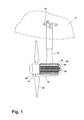
- an aircraft 10 may include a RAT system 12 for generating electrical power for the aircraft 10 when the RAT system 12 is exposed to the airstream exterior of the aircraft 10.
- the RAT system 12 may include a RAT 14, which may be suspended from the aircraft 10 by a strut 16 and mounting assembly 18.
- the RAT 14 may be stored within a suitable compartment in the fuselage or wing of the aircraft 10 and may be deployed quickly and easily by moving the strut 16 relative to the mounting assembly 18, thereby moving the RAT system 12 to an exposed position within the air stream flowing past the aircraft 10.
- the RAT 14 includes a housing 20 in which are located an electrical generator 22, a gearbox 23 having a gearbox output element 24, and an integrated heat exchanger 25.
- a turbine in the form of multiple blades 26 projecting from a rotary hub 28 is provided on one end of the housing 20. Although only two blades 26 have been shown in the illustrated embodiment it is contemplated that any number of blades 26 may be used.
- the turbine further includes a turbine output shaft 30 may be operably coupled at a first end 32 to the blades 26 such that rotation of the blades 26 rotates the turbine output shaft 30.
- the turbine output shaft 30 may be operably coupled to the blades 26 in any suitable manner and may project rearwardly from the blades 26 to provide a rotary output for driving an auxiliary power unit, such as the electrical generator 22.
- a rotor shaft 34 may extend from the blades 26 and may be splined, or otherwise suitably mechanically coupled, with the turbine output shaft 30 such that rotation of the blades 26 is transferred through the rotor shaft 34 to the turbine output shaft 30.
- the blades 26 or a portion of the rotary hub 28 may be coupled directly to the turbine output shaft 30.
- a second end 36 of the turbine output shaft 30 may be operably coupled to a portion of the gearbox 23.
- the turbine output shaft 30 may be rotatably supported within bearings 38 mounted in the rotary hub 28.
- the housing 20 comprises a body 44, which is closed by opposing first and second end caps 46, 48, to provide a common housing defining an interior 40 for receiving both the gearbox 23 and generator 22.
- a wall 42 is provided to separate the gearbox portion of the interior 40 from the generator portion of the interior 40 to physically and fluidly separate the two portions of the interior 40.
- the housing 20 may also include a plurality of heat-dissipating fins or cooling fins 50.
- the cooling fins 50 may be formed in any suitable manner such that they project outwardly from a periphery 52 of the housing 20.
- the cooling fins 50 may be spaced about the periphery 52 of the body 44. The size and number of the cooling fins 50 may be a function of the specific heat dissipation requirements of the RAT system 12.
- the generator 22 comprises a stator 54 and a rotor 56 located within the generator portion of the interior 40.
- the rotor 56 may be operably coupled to the gearbox output element 24 such that the gearbox output element 24 may provide driving force for the rotor 56 such that electrical power may be generated.
- the generator 22 may be suitably coupled via conductor cables 58 to the aircraft 10.
- the RAT system 12 may be carried at the lower end of strut 16, which may be hollow.
- the hollow strut 16 may define a passage 59 through which the conductor cables 58 from the generator 22 may pass to the aircraft 10. In this manner, the conductor cables 58, and any other linkages between the RAT system 12 and the aircraft 10, may be protectively concealed within the strut 16 to lessen damage.
- the gearbox 23 may include a speed-increasing gear train 60. More specifically, an input gear 62, a first idler gear 64, a second idler gear 66, and an output drive gear 68 may be included in the speed-increasing gear train 60.
- the input gear 62 may be referred to by other names but has been referenced here as an input gear because power is input to the speed-increasing gear train 60 of the gearbox 23 at the input gear end of the speed-increasing gear train 60.
- the input gear 62 may be splined or otherwise suitably mechanically coupled to the turbine output shaft 30, generally near its second end 36.
- Input gear 62 meshes with the first idler gear 64, which has a height spanning across both the input gear 62 and the second idler gear 66.
- first idler gear 64 may mesh with the second idler gear 66.
- the second idler gear 66 may in turn mesh with the output drive gear 68, which may be splined, or otherwise suitably mechanically coupled, to the gearbox output element 24, which is illustrated as a shaft that may be rotatably supported by bearings 70.
- the bearings 70 may be provided in an arrangement to rotatably support the gearbox output element 24 coaxially with the turbine output shaft 30.
- gearbox 23 is illustrated as being located within the housing 20 with the generator 22 it may be in a separate housing coupled to the generator 22.
- a coolant circuit 72 is included in the integrated heat exchanger 25 for cooling the gearbox 23 and the generator 22.
- the coolant circuit 72 is illustrated as extending from the gearbox 23 to the generator 22 and is formed at least in part by passageways 74 within the housing 20 such that heat from the gearbox 23 and the generator 22 is transferred to the housing 20 by a coolant 76 circulating in the coolant circuit 72.
- the passageways 74 may be formed within the body 44 such that they extend a length of the body 44.
- the passageways 74 may be formed within the first and second end caps 46 and 48 such that they fluidly couple the passageways 74 within the body 44 to each other.
- a coolant sump 78 may be fluidly coupled to the coolant circuit 72 to supply coolant 76 to the coolant circuit 72. Any suitable coolant 76 may be used including, by way of non-limiting example, oil.
- a pump 80 may be fluidly coupled to at least one of the coolant sump 78 and the coolant circuit 72 to recirculate the coolant 76 from the coolant sump 78 through the coolant circuit 72.
- the pump 80 may be any suitable type of pump and by way of non-limiting examples may include a simple gear pump, or a gerotor type pump. It is contemplated that regardless of the type of pump used the pump 80 may be driven off of the speed-increasing gear train 60.
- a filter assembly 82 may also be located within the gear box 23 along the coolant circuit 72, preferably adjacent the pump 80 to filter the coolant 76 to prevent plugging of the coolant circuit 72.
- the coolant sump 78 and pump 80 are illustrated as being located within the gearbox 23. In this configuration, as better illustrated in FIG. 3 , the input gear 62 may contact the coolant 76 within the coolant sump 78 such that the coolant 76 may be used as lubrication for the speed-increasing gear train 60.
- the RAT 14 is extended into the airstream surrounding the aircraft, the airstream flowing over the blades 26 causes the blades 26 to rotate, which in turn causes the turbine output shaft 30 to rotate at the same rotations per minutes as the blades 26.
- the turbine output shaft 30 drives the input gear 62 of the speed-increasing gear train 60, which in turn drives the first and second idler gears 64 and 66, which in turn drives the output drive gear 68 and the gearbox output element 24.
- the speed-increasing gear train 60 causes the gearbox output element 24 to rotate at a faster speed than the blades 26 and acts to convert the low speed incoming rotation to high speed rotation suitable for generating electricity.
- the generator 22 may be configured to generate at least 30kW at 20,000 rpm. More specifically, the ratio of the input gear 62 to the output drive gear 68 may be selected such that the output drive gear 68 rotates at a substantially greater speed than the input gear 62.
- the gear configuration and gear ratios in the speed-increasing gear train 60 may be selected such that the gearbox output element 24 rotates at 20,000 rpm in response to a predetermined rotational speed of the turbine output shaft of 6,000 rpm.
- the rotor 56 is driven by the gearbox output element 24 and causes the generator 22 to produce electricity that may be transferred to the aircraft 10 through the conductor cables 58.
- the RAT system 12 Along with producing electricity, the RAT system 12 also produces heat.
- the pump 80 may also be driven by the speed-increasing gear train 60 and may operate to circulate the coolant 76 within the cooling circuit 72.
- the coolant 76 may be pumped by the pump 80 through the coolant circuit 72 including the multiple passageways 74 within the body 44 and first and second end caps 46 and 48 before the coolant flows into the coolant sump 78 and through the filter assembly 82 before being pumped by the pump 80 through the coolant circuit 72 again.
- the coolant flows through the coolant circuit 72 it may absorb heat from the gearbox 23 and interior 40 of the generator 22, which is hotter than the coolant.
- the coolant 76 As the coolant 76 is pumped through the cooling circuit 72 it carries the displaced heat.
- the displaced heat in the coolant 76 may then be dissipated through the housing 20 and its cooling fins 50.
- the cooled coolant repeats this cycle, to continuously remove heat from the gearbox 23 and generator 22.
- the RAT 14, gearbox 23, and generator 22 are linearly arranged such that the airstream passing through the blades 26 flows over the gearbox 23 and the housing 20 including the cooling fins 50 to provide for heat transfer from the circulating coolant 76 to the airstream.
- the cooling fins 50 add to the surface area of the generator 22 and aid in transferring heat to the surrounding air stream allowing for greater heat dissipation from the RAT system 12.
- the speed-increasing gear train 60 may also provide the driving power for a hydraulic pump (not shown).
- a hydraulic pump may be located such that it may rotate at the same increased speed as the generator 22 or may be located such that it may rotate at the slower turbine speed while the electrical generator is allowed to rotate at the increased speed.
- the design and placement of the various components may be rearranged such that a number of different in-line configurations could be realized.
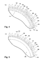
- FIG. 4 illustrates an alternative RAT system 112 with an integrated heat exchanger 125 according to a second embodiment of the invention.
- the second embodiment is similar to the first embodiment; therefore, like parts will be identified with like numerals increased by 100, with it being understood that the description of the like parts of the first embodiment applies to the second embodiment, unless otherwise noted.
- the difference between the first embodiment and the second embodiment is that the cooling fins 150 of the heat exchanger 125 also have passageways 190, which may be fluidly coupled to the passageways 174 and the remainder of the cooling circuit 172. Although each cooling fin 150 has been illustrated as having a passageway 190 this need not be the case. It is possible for some, but not all, of the cooling fins 150 to have a passageway 190.
- passageways 190 being located in the cooling fins 150 the number of passageways in the housing 120 may be reduced.
- the coolant in both the passageways 174 and the passageways 190 may further aid in displacing heat from the gearbox 23 and generator 122 to the surrounding airstream.
- FIG. 5 illustrates a third embodiment wherein the RAT system 212 only includes the passageways 290 located within the fins 250.
- the third embodiment is similar to the first embodiment; therefore, like parts will be identified with like numerals increased by 200, with it being understood that the description of the like parts of the first embodiment applies to the third embodiment, unless otherwise noted.
- the passageways 290 take the place of the passageways within the body 244.
- the first and second end caps would include corresponding fluid passageways to allow coolant pumped through the passageways 290 to be in fluid communication with the remainder of the cooling circuit 272 including the coolant sump and pump (not shown).
- the embodiments disclosed herein provide a RAT system with an integrated heat exchanger.
- One advantage that may be realized in the above embodiments is that the above described embodiments can effectively remove heat from the high power RAT system.
- the cooling fins along the housing increase the cooling surface area and the coolant circuit provides an effective means for dissipating heat from the gearbox and generator.
- Another advantage is that the above described embodiments are configured as closed loop systems where oil in the coolant sump is recirculated to remove heat from the generator while also providing lubrication to the gears in gearbox.
Description
- Ram Air Turbine (RAT) systems are used in contemporary aircraft as emergency or supplemental power systems. They typically have a turbine, with a rotating hub and a plurality of blades, operably coupled to a generator to provide the driving source for the generator. Initially in flight they are stowed in a compartment of the aircraft fuselage, covered by a compartment door. When needed as a source of emergency or supplemental power, the RAT system is deployed from the fuselage into the surrounding airstream, which drives the blades to rotate the generator to extract energy from the airstream.
- An example is shown in
WO 02 098 736 - The present invention provides a ram air turbine system for generating electrical power in an aircraft when the system is exposed to an airstream exterior of the aircraft, the ram air turbine system being in accordance with claim 1 herein.
- In the drawings:
-
FIG. 1 is a side view illustrating a portion of an aircraft having a ram air turbine with integrated heat exchanger in accordance with one embodiment of the invention; -
FIG. 2 is a schematic cross sectional view of the ram air turbine and integrated heat exchanger ofFIG. 1 ; -
FIG. 3 is a schematic cross sectional view of the ram air turbine and integrated heat exchanger ofFIG. 1 ; -
FIG. 4 is a schematic cross sectional view of a portion of a ram air turbine with an integrated heat exchanger according to a second embodiment of the invention; and -
FIG. 5 is a schematic cross sectional view of a portion of a ram air turbine with an integrated heat exchanger according to a third embodiment of the invention. - As illustrated in
FIG. 1 , anaircraft 10 may include aRAT system 12 for generating electrical power for theaircraft 10 when theRAT system 12 is exposed to the airstream exterior of theaircraft 10. TheRAT system 12 may include aRAT 14, which may be suspended from theaircraft 10 by astrut 16 and mountingassembly 18. The RAT 14 may be stored within a suitable compartment in the fuselage or wing of theaircraft 10 and may be deployed quickly and easily by moving thestrut 16 relative to themounting assembly 18, thereby moving theRAT system 12 to an exposed position within the air stream flowing past theaircraft 10. As illustrated inFIG. 2 , the RAT 14 includes ahousing 20 in which are located anelectrical generator 22, agearbox 23 having agearbox output element 24, and an integratedheat exchanger 25. A turbine in the form ofmultiple blades 26 projecting from arotary hub 28 is provided on one end of thehousing 20. Although only twoblades 26 have been shown in the illustrated embodiment it is contemplated that any number ofblades 26 may be used. The turbine further includes aturbine output shaft 30 may be operably coupled at afirst end 32 to theblades 26 such that rotation of theblades 26 rotates theturbine output shaft 30. Theturbine output shaft 30 may be operably coupled to theblades 26 in any suitable manner and may project rearwardly from theblades 26 to provide a rotary output for driving an auxiliary power unit, such as theelectrical generator 22. By way of non-limiting example, arotor shaft 34 may extend from theblades 26 and may be splined, or otherwise suitably mechanically coupled, with theturbine output shaft 30 such that rotation of theblades 26 is transferred through therotor shaft 34 to theturbine output shaft 30. Alternatively, theblades 26 or a portion of therotary hub 28 may be coupled directly to theturbine output shaft 30. Asecond end 36 of theturbine output shaft 30 may be operably coupled to a portion of thegearbox 23. Theturbine output shaft 30 may be rotatably supported withinbearings 38 mounted in therotary hub 28. - The
housing 20, as illustrated, comprises abody 44, which is closed by opposing first andsecond end caps interior 40 for receiving both thegearbox 23 andgenerator 22. Awall 42 is provided to separate the gearbox portion of theinterior 40 from the generator portion of theinterior 40 to physically and fluidly separate the two portions of theinterior 40. Thehousing 20 may also include a plurality of heat-dissipating fins or cooling fins 50. Thecooling fins 50 may be formed in any suitable manner such that they project outwardly from aperiphery 52 of thehousing 20. The cooling fins 50 may be spaced about theperiphery 52 of thebody 44. The size and number of thecooling fins 50 may be a function of the specific heat dissipation requirements of theRAT system 12. - The
generator 22 comprises astator 54 and arotor 56 located within the generator portion of theinterior 40. Therotor 56 may be operably coupled to thegearbox output element 24 such that thegearbox output element 24 may provide driving force for therotor 56 such that electrical power may be generated. Thegenerator 22 may be suitably coupled viaconductor cables 58 to theaircraft 10. As illustrated, theRAT system 12 may be carried at the lower end ofstrut 16, which may be hollow. Thehollow strut 16 may define apassage 59 through which the conductor cables 58 from thegenerator 22 may pass to theaircraft 10. In this manner, theconductor cables 58, and any other linkages between theRAT system 12 and theaircraft 10, may be protectively concealed within thestrut 16 to lessen damage. - The
gearbox 23 may include a speed-increasinggear train 60. More specifically, aninput gear 62, afirst idler gear 64, asecond idler gear 66, and anoutput drive gear 68 may be included in the speed-increasinggear train 60. Theinput gear 62 may be referred to by other names but has been referenced here as an input gear because power is input to the speed-increasinggear train 60 of thegearbox 23 at the input gear end of the speed-increasinggear train 60. Theinput gear 62 may be splined or otherwise suitably mechanically coupled to theturbine output shaft 30, generally near itssecond end 36.Input gear 62 meshes with thefirst idler gear 64, which has a height spanning across both theinput gear 62 and thesecond idler gear 66. In this manner, thefirst idler gear 64 may mesh with thesecond idler gear 66. Thesecond idler gear 66 may in turn mesh with theoutput drive gear 68, which may be splined, or otherwise suitably mechanically coupled, to thegearbox output element 24, which is illustrated as a shaft that may be rotatably supported bybearings 70. Thebearings 70 may be provided in an arrangement to rotatably support thegearbox output element 24 coaxially with theturbine output shaft 30. - Other configurations for the
gearbox 23, including thegear train 60 are possible. For example, although thegearbox 23 is illustrated as being located within thehousing 20 with thegenerator 22 it may be in a separate housing coupled to thegenerator 22. - A
coolant circuit 72 is included in the integratedheat exchanger 25 for cooling thegearbox 23 and thegenerator 22. Thecoolant circuit 72 is illustrated as extending from thegearbox 23 to thegenerator 22 and is formed at least in part bypassageways 74 within thehousing 20 such that heat from thegearbox 23 and thegenerator 22 is transferred to thehousing 20 by acoolant 76 circulating in thecoolant circuit 72. More specifically, thepassageways 74 may be formed within thebody 44 such that they extend a length of thebody 44. Thepassageways 74 may be formed within the first andsecond end caps passageways 74 within thebody 44 to each other. - A
coolant sump 78 may be fluidly coupled to thecoolant circuit 72 to supplycoolant 76 to thecoolant circuit 72. Anysuitable coolant 76 may be used including, by way of non-limiting example, oil. Apump 80 may be fluidly coupled to at least one of thecoolant sump 78 and thecoolant circuit 72 to recirculate thecoolant 76 from thecoolant sump 78 through thecoolant circuit 72. Thepump 80 may be any suitable type of pump and by way of non-limiting examples may include a simple gear pump, or a gerotor type pump. It is contemplated that regardless of the type of pump used thepump 80 may be driven off of the speed-increasinggear train 60. Afilter assembly 82 may also be located within thegear box 23 along thecoolant circuit 72, preferably adjacent thepump 80 to filter thecoolant 76 to prevent plugging of thecoolant circuit 72. Thecoolant sump 78 andpump 80 are illustrated as being located within thegearbox 23. In this configuration, as better illustrated inFIG. 3 , theinput gear 62 may contact thecoolant 76 within thecoolant sump 78 such that thecoolant 76 may be used as lubrication for the speed-increasinggear train 60. - During operation of the
RAT system 12, theRAT 14 is extended into the airstream surrounding the aircraft, the airstream flowing over theblades 26 causes theblades 26 to rotate, which in turn causes theturbine output shaft 30 to rotate at the same rotations per minutes as theblades 26. Theturbine output shaft 30 drives theinput gear 62 of the speed-increasinggear train 60, which in turn drives the first and second idler gears 64 and 66, which in turn drives theoutput drive gear 68 and thegearbox output element 24. The speed-increasinggear train 60 causes thegearbox output element 24 to rotate at a faster speed than theblades 26 and acts to convert the low speed incoming rotation to high speed rotation suitable for generating electricity. - By way of non-limiting example the
generator 22 may be configured to generate at least 30kW at 20,000 rpm. More specifically, the ratio of theinput gear 62 to theoutput drive gear 68 may be selected such that theoutput drive gear 68 rotates at a substantially greater speed than theinput gear 62. The gear configuration and gear ratios in the speed-increasinggear train 60 may be selected such that thegearbox output element 24 rotates at 20,000 rpm in response to a predetermined rotational speed of the turbine output shaft of 6,000 rpm. Therotor 56 is driven by thegearbox output element 24 and causes thegenerator 22 to produce electricity that may be transferred to theaircraft 10 through theconductor cables 58. - Along with producing electricity, the
RAT system 12 also produces heat. During operation thepump 80 may also be driven by the speed-increasinggear train 60 and may operate to circulate thecoolant 76 within thecooling circuit 72. Thecoolant 76 may be pumped by thepump 80 through thecoolant circuit 72 including themultiple passageways 74 within thebody 44 and first and second end caps 46 and 48 before the coolant flows into thecoolant sump 78 and through thefilter assembly 82 before being pumped by thepump 80 through thecoolant circuit 72 again. When the coolant flows through thecoolant circuit 72 it may absorb heat from thegearbox 23 andinterior 40 of thegenerator 22, which is hotter than the coolant. As thecoolant 76 is pumped through thecooling circuit 72 it carries the displaced heat. The displaced heat in thecoolant 76 may then be dissipated through thehousing 20 and itscooling fins 50. The cooled coolant repeats this cycle, to continuously remove heat from thegearbox 23 andgenerator 22. TheRAT 14,gearbox 23, andgenerator 22 are linearly arranged such that the airstream passing through theblades 26 flows over thegearbox 23 and thehousing 20 including the coolingfins 50 to provide for heat transfer from the circulatingcoolant 76 to the airstream. The coolingfins 50 add to the surface area of thegenerator 22 and aid in transferring heat to the surrounding air stream allowing for greater heat dissipation from theRAT system 12. - Many other possible embodiments and configurations in addition to that shown in the above figures are contemplated by the present disclosure. For example, the speed-increasing
gear train 60 may also provide the driving power for a hydraulic pump (not shown). Such a hydraulic pump may be located such that it may rotate at the same increased speed as thegenerator 22 or may be located such that it may rotate at the slower turbine speed while the electrical generator is allowed to rotate at the increased speed. Further, the design and placement of the various components may be rearranged such that a number of different in-line configurations could be realized. - Furthermore,
FIG. 4 illustrates analternative RAT system 112 with anintegrated heat exchanger 125 according to a second embodiment of the invention. The second embodiment is similar to the first embodiment; therefore, like parts will be identified with like numerals increased by 100, with it being understood that the description of the like parts of the first embodiment applies to the second embodiment, unless otherwise noted. The difference between the first embodiment and the second embodiment is that the coolingfins 150 of theheat exchanger 125 also havepassageways 190, which may be fluidly coupled to thepassageways 174 and the remainder of thecooling circuit 172. Although each coolingfin 150 has been illustrated as having apassageway 190 this need not be the case. It is possible for some, but not all, of the coolingfins 150 to have apassageway 190. Further, with some of thepassageways 190 being located in the coolingfins 150 the number of passageways in thehousing 120 may be reduced. The coolant in both thepassageways 174 and thepassageways 190 may further aid in displacing heat from thegearbox 23 andgenerator 122 to the surrounding airstream. -
FIG. 5 illustrates a third embodiment wherein theRAT system 212 only includes thepassageways 290 located within thefins 250. The third embodiment is similar to the first embodiment; therefore, like parts will be identified with like numerals increased by 200, with it being understood that the description of the like parts of the first embodiment applies to the third embodiment, unless otherwise noted. In the case of the third embodiment thepassageways 290 take the place of the passageways within thebody 244. Thus, the first and second end caps (not shown) would include corresponding fluid passageways to allow coolant pumped through thepassageways 290 to be in fluid communication with the remainder of the cooling circuit 272 including the coolant sump and pump (not shown). - The embodiments disclosed herein provide a RAT system with an integrated heat exchanger. One advantage that may be realized in the above embodiments is that the above described embodiments can effectively remove heat from the high power RAT system. The cooling fins along the housing increase the cooling surface area and the coolant circuit provides an effective means for dissipating heat from the gearbox and generator. Another advantage is that the above described embodiments are configured as closed loop systems where oil in the coolant sump is recirculated to remove heat from the generator while also providing lubrication to the gears in gearbox.
- When designing aircraft components, important factors to address are size, weight, and reliability. The above described RAT systems have a decreased number of parts as there is not a separate heat exchanger or separate plumbing connections. This results in a lower weight, smaller sized, and increased reliability system. The lower number of parts and reduced maintenance will lead to a lower product costs and lower operating costs. Reduced weight and size correlate to competitive advantages during flight.
- This written description uses examples to disclose the invention, including the best mode, and also to enable any person skilled in the art to practice the invention, including making and using any devices or systems and performing any incorporated methods. The patentable scope of the invention is defined by the claims, and may include other examples that occur to those skilled in the art. Such other examples are intended to be within the scope of the claims if they have structural elements that do not differ from the literal language of the claims, or if they include equivalent structural elements with insubstantial differences from the literal languages of the claims.
Claims (12)
- A ram air turbine system (12) for generating electrical power in an aircraft (10) when the system is exposed to an airstream exterior of the aircraft, the system comprising:a turbine (14) having multiple blades (26) and a turbine output shaft (30) operably coupled to the blades such that rotation of the blades rotates the turbine output shaft;a housing (20) defining an interior;a gearbox (23) located within the interior (40) and having a speed-increasing gear train (60) with a gearbox output element (24) and operably coupled to the turbine output shaft such that the gearbox output element rotates at a faster speed than the blades;a generator (22) located within the interior and having a stator (54) and a rotor (56) where the rotor operably couples to the gearbox output element (24); andan integrated heat exchanger (25) for cooling the gearbox (23) and the generator having a coolant circuit (72) extending from the gearbox (23) to the generator (22) and formed at least in part by passageways (74) within the housing (20) such that heat from the gearbox and the generator is transferred to the housing by coolant (76) circulating in the coolant circuit;wherein the turbine, gearbox (23) and generator (22) are linearly arranged such that the airstream passing through the blades (26) flows over the gearbox (23) and the generator (22) to provide for heat transfer from the circulating coolant (76) to the airstream via the housing (20).
- The ram air turbine system (12) of claim 1 wherein the housing (20) further comprises outwardly projecting cooling fins (50).
- The ram air turbine system (112,212) of claim 2, wherein at least some of the passageways (190, 290) are located in the cooling fins (150, 250).
- The ram air turbine system of either of claim 2 or 3, wherein at least some of the passageways (74) are located in the housing (20) at locations other than the cooling fins (50).
- The ram air turbine system of any of claims 2 to 4, wherein the cooling fins (50) are spaced about a periphery (52) of the housing (20).
- The ram air turbine system (12) of any preceding claim, further comprising a coolant sump (78) fluidly coupled to the coolant circuit (72) to supply coolant (76) to the coolant circuit.
- The ram air turbine system (12) of claim 6, further comprising a pump (80) fluidly coupled to at least one of the coolant sump (78) and the coolant circuit (72) to recirculate coolant (76) from the coolant sump through the coolant circuit.
- The ram air turbine system (12) of claim 7, wherein the sump (78) and pump (80) are located within the gearbox (23).
- The ram air turbine system (12) of claim 8, wherein the speed-increasing gear train (60) drives the pump (80).
- The ram air turbine system (12) of any preceding claim, wherein the generator (22) is configured to generate at least 30kW at 20,000 rpm.
- The ram air turbine system (12) of any preceding claim, wherein the speed-increasing gear train (60) is selected such that the gearbox output element (24) rotates at 20,000 rpm in response to a predetermined rotational speed of the turbine output shaft (30).
- The ram air turbine system (12) of claim 11, wherein the predetermined rotational speed of the turbine output shaft (30) is 6,000 rpm.
Applications Claiming Priority (1)
| Application Number | Priority Date | Filing Date | Title |
|---|---|---|---|
| US13/238,880 US8864448B2 (en) | 2011-09-21 | 2011-09-21 | Ram air turbine with integrated heat exchanger |
Publications (2)
| Publication Number | Publication Date |
|---|---|
| EP2572989A1 EP2572989A1 (en) | 2013-03-27 |
| EP2572989B1 true EP2572989B1 (en) | 2014-03-26 |
Family
ID=46939594
Family Applications (1)
| Application Number | Title | Priority Date | Filing Date |
|---|---|---|---|
| EP12184550.7A Not-in-force EP2572989B1 (en) | 2011-09-21 | 2012-09-14 | Ram air turbine with integrated heat exchanger |
Country Status (6)
| Country | Link |
|---|---|
| US (1) | US8864448B2 (en) |
| EP (1) | EP2572989B1 (en) |
| JP (1) | JP6088184B2 (en) |
| CN (1) | CN103016206B (en) |
| BR (1) | BR102012022326A2 (en) |
| CA (1) | CA2790062A1 (en) |
Families Citing this family (11)
| Publication number | Priority date | Publication date | Assignee | Title |
|---|---|---|---|---|
| US9217417B2 (en) * | 2012-10-31 | 2015-12-22 | Ge Aviation Systems Llc | Ram air turbine generator with external rotor having permanent magnets |
| US10161416B2 (en) | 2014-06-02 | 2018-12-25 | Hamilton Sundstrand Corporation | Rotary machine heat sink |
| US9643729B2 (en) | 2014-06-20 | 2017-05-09 | Electronair Llc | Energy cell regenerative system for electrically powered aircraft |
| US9828109B2 (en) | 2014-07-23 | 2017-11-28 | Pratt & Whitney Canada Corp. | Apparatus and methods for powering an electrical device associated with an aircraft rotor |
| WO2016018498A1 (en) * | 2014-07-31 | 2016-02-04 | Sikorsky Aircraft Corporation | Gearbox oil cooling assembly |
| US10094293B2 (en) | 2014-08-22 | 2018-10-09 | Pratt & Whitney Canada Corp. | In flight restart system and method for free turbine engine |
| US10399694B2 (en) * | 2015-09-02 | 2019-09-03 | Ge Aviation Systems Llc | Ram air turbine system |
| US10077118B2 (en) * | 2016-06-06 | 2018-09-18 | Hamilton Sundstrand Corporation | Integral rat generator cooling holes |
| CN105927466A (en) * | 2016-06-27 | 2016-09-07 | 郭全有 | Wind power generation apparatus, and automobile and transportation means comprising wind power generation apparatus |
| US10348162B1 (en) * | 2017-12-21 | 2019-07-09 | Ge Aviation Systems Llc | Method and assembly of an electric machine |
| CN111271190B (en) * | 2018-12-04 | 2022-11-08 | 中国航空工业集团公司金城南京机电液压工程研究中心 | Ram air turbine miniflow temperature control circulation structure |
Family Cites Families (12)
| Publication number | Priority date | Publication date | Assignee | Title |
|---|---|---|---|---|
| US2761984A (en) * | 1952-01-21 | 1956-09-04 | Kleinschanzlin Pumpen Ag | Core and shell for electromotors |
| US5249924A (en) * | 1992-02-21 | 1993-10-05 | Southwest Aerospace Corporation | RAM air turbine |
| US6580179B2 (en) | 2001-06-07 | 2003-06-17 | Honeywell International Inc. | Ram air turbine with high power density generator and self-contained fluid cooling loop |
| US6676379B2 (en) * | 2001-12-06 | 2004-01-13 | Honeywell International Inc. | Ram air turbine with speed increasing gearbox |
| US7019415B2 (en) | 2004-03-22 | 2006-03-28 | Honeywell International Inc. | Electrical power generation system and method for mitigating corona discharge |
| WO2006036541A1 (en) | 2004-09-22 | 2006-04-06 | Hamilton Sundstrand Corporation | Motor cooling path and thrust bearing load design |
| US7708527B2 (en) | 2006-01-12 | 2010-05-04 | Honeywell International Inc. | Ram air turbine with compound geartrain gearbox |
| US7445102B2 (en) | 2006-02-27 | 2008-11-04 | Honeywell International Inc. | Air turbine starter assembly |
| DE102007012408A1 (en) * | 2007-03-15 | 2008-09-18 | Aerodyn Engineering Gmbh | Wind turbines with load-transmitting components |
| US20080231126A1 (en) * | 2007-03-23 | 2008-09-25 | Rajendra Narayan Telore | Motor cooling arrangement |
| US9803694B2 (en) * | 2010-01-11 | 2017-10-31 | Siemens Aktiengesellschaft | Direct drive wind turbine with a cooling system |
| FR2956379B1 (en) | 2010-02-17 | 2012-08-24 | Technofan | VENTILATION APPARATUS FOR AIRCRAFT |
-
2011
- 2011-09-21 US US13/238,880 patent/US8864448B2/en active Active
-
2012
- 2012-09-04 BR BRBR102012022326-0A patent/BR102012022326A2/en not_active IP Right Cessation
- 2012-09-13 CA CA2790062A patent/CA2790062A1/en not_active Abandoned
- 2012-09-13 JP JP2012201035A patent/JP6088184B2/en not_active Expired - Fee Related
- 2012-09-14 EP EP12184550.7A patent/EP2572989B1/en not_active Not-in-force
- 2012-09-21 CN CN201210353964.5A patent/CN103016206B/en active Active
Also Published As
| Publication number | Publication date |
|---|---|
| EP2572989A1 (en) | 2013-03-27 |
| JP2013068217A (en) | 2013-04-18 |
| CA2790062A1 (en) | 2013-03-21 |
| US20130071232A1 (en) | 2013-03-21 |
| CN103016206B (en) | 2016-05-18 |
| US8864448B2 (en) | 2014-10-21 |
| CN103016206A (en) | 2013-04-03 |
| BR102012022326A2 (en) | 2013-12-03 |
| JP6088184B2 (en) | 2017-03-01 |
Similar Documents
| Publication | Publication Date | Title |
|---|---|---|
| EP2572989B1 (en) | Ram air turbine with integrated heat exchanger | |
| US6580179B2 (en) | Ram air turbine with high power density generator and self-contained fluid cooling loop | |
| US11092031B2 (en) | Drive system for an aircraft | |
| US10800539B2 (en) | Propulsion engine for an aircraft | |
| US20180127103A1 (en) | Fully Integrated Hybrid Electric Jet Engine | |
| US20150214816A1 (en) | Gear-driven generator with offset axis of rotation and integrated cooling system | |
| US10399694B2 (en) | Ram air turbine system | |
| EP1881194A1 (en) | Cooling device | |
| CN109642521A (en) | Propelling motor for aircraft | |
| CN101657637A (en) | Wind driven electric power generator | |
| JP2011196183A (en) | Wind turbine generator | |
| EP2727840A2 (en) | Ram air turbine generator with external rotor having permanent magnets | |
| EP2573389B1 (en) | Cooling and climate control system and method for a wind turbine | |
| AU2008228654A1 (en) | Wind turbine comprising load transmitting components | |
| WO2011133024A2 (en) | Highly integrated energy conversion system for wind, tidal or hydro turbines | |
| JP2013068217A5 (en) | ||
| CN115004524A (en) | System for cooling a propeller drive having a plurality of electric motors | |
| EP2784306B1 (en) | Cooling device for a wind turbine generator | |
| EP2589801A1 (en) | Wind-powered electricity generator | |
| KR101638867B1 (en) | Wind turbine comprising integrated cooling system for the heat generating component inside the nacelle assembly. | |
| JP2013181426A (en) | Rotational power unit for wind power generation apparatus and wind power generation apparatus |
Legal Events
| Date | Code | Title | Description |
|---|---|---|---|
| PUAI | Public reference made under article 153(3) epc to a published international application that has entered the european phase |
Free format text: ORIGINAL CODE: 0009012 |
|
| AK | Designated contracting states |
Kind code of ref document: A1 Designated state(s): AL AT BE BG CH CY CZ DE DK EE ES FI FR GB GR HR HU IE IS IT LI LT LU LV MC MK MT NL NO PL PT RO RS SE SI SK SM TR |
|
| AX | Request for extension of the european patent |
Extension state: BA ME |
|
| GRAP | Despatch of communication of intention to grant a patent |
Free format text: ORIGINAL CODE: EPIDOSNIGR1 |
|
| 17P | Request for examination filed |
Effective date: 20130927 |
|
| RBV | Designated contracting states (corrected) |
Designated state(s): AL AT BE BG CH CY CZ DE DK EE ES FI FR GB GR HR HU IE IS IT LI LT LU LV MC MK MT NL NO PL PT RO RS SE SI SK SM TR |
|
| INTG | Intention to grant announced |
Effective date: 20131029 |
|
| GRAS | Grant fee paid |
Free format text: ORIGINAL CODE: EPIDOSNIGR3 |
|
| GRAA | (expected) grant |
Free format text: ORIGINAL CODE: 0009210 |
|
| AK | Designated contracting states |
Kind code of ref document: B1 Designated state(s): AL AT BE BG CH CY CZ DE DK EE ES FI FR GB GR HR HU IE IS IT LI LT LU LV MC MK MT NL NO PL PT RO RS SE SI SK SM TR |
|
| REG | Reference to a national code |
Ref country code: GB Ref legal event code: FG4D |
|
| REG | Reference to a national code |
Ref country code: CH Ref legal event code: EP |
|
| REG | Reference to a national code |
Ref country code: AT Ref legal event code: REF Ref document number: 658838 Country of ref document: AT Kind code of ref document: T Effective date: 20140415 |
|
| REG | Reference to a national code |
Ref country code: IE Ref legal event code: FG4D |
|
| REG | Reference to a national code |
Ref country code: DE Ref legal event code: R096 Ref document number: 602012001216 Country of ref document: DE Effective date: 20140508 |
|
| PG25 | Lapsed in a contracting state [announced via postgrant information from national office to epo] |
Ref country code: LT Free format text: LAPSE BECAUSE OF FAILURE TO SUBMIT A TRANSLATION OF THE DESCRIPTION OR TO PAY THE FEE WITHIN THE PRESCRIBED TIME-LIMIT Effective date: 20140326 Ref country code: NO Free format text: LAPSE BECAUSE OF FAILURE TO SUBMIT A TRANSLATION OF THE DESCRIPTION OR TO PAY THE FEE WITHIN THE PRESCRIBED TIME-LIMIT Effective date: 20140626 |
|
| REG | Reference to a national code |
Ref country code: AT Ref legal event code: MK05 Ref document number: 658838 Country of ref document: AT Kind code of ref document: T Effective date: 20140326 |
|
| REG | Reference to a national code |
Ref country code: NL Ref legal event code: VDEP Effective date: 20140326 |
|
| REG | Reference to a national code |
Ref country code: LT Ref legal event code: MG4D |
|
| PG25 | Lapsed in a contracting state [announced via postgrant information from national office to epo] |
Ref country code: FI Free format text: LAPSE BECAUSE OF FAILURE TO SUBMIT A TRANSLATION OF THE DESCRIPTION OR TO PAY THE FEE WITHIN THE PRESCRIBED TIME-LIMIT Effective date: 20140326 Ref country code: SE Free format text: LAPSE BECAUSE OF FAILURE TO SUBMIT A TRANSLATION OF THE DESCRIPTION OR TO PAY THE FEE WITHIN THE PRESCRIBED TIME-LIMIT Effective date: 20140326 |
|
| PG25 | Lapsed in a contracting state [announced via postgrant information from national office to epo] |
Ref country code: HR Free format text: LAPSE BECAUSE OF FAILURE TO SUBMIT A TRANSLATION OF THE DESCRIPTION OR TO PAY THE FEE WITHIN THE PRESCRIBED TIME-LIMIT Effective date: 20140326 Ref country code: LV Free format text: LAPSE BECAUSE OF FAILURE TO SUBMIT A TRANSLATION OF THE DESCRIPTION OR TO PAY THE FEE WITHIN THE PRESCRIBED TIME-LIMIT Effective date: 20140326 Ref country code: RS Free format text: LAPSE BECAUSE OF FAILURE TO SUBMIT A TRANSLATION OF THE DESCRIPTION OR TO PAY THE FEE WITHIN THE PRESCRIBED TIME-LIMIT Effective date: 20140326 |
|
| PG25 | Lapsed in a contracting state [announced via postgrant information from national office to epo] |
Ref country code: IS Free format text: LAPSE BECAUSE OF FAILURE TO SUBMIT A TRANSLATION OF THE DESCRIPTION OR TO PAY THE FEE WITHIN THE PRESCRIBED TIME-LIMIT Effective date: 20140726 Ref country code: RO Free format text: LAPSE BECAUSE OF FAILURE TO SUBMIT A TRANSLATION OF THE DESCRIPTION OR TO PAY THE FEE WITHIN THE PRESCRIBED TIME-LIMIT Effective date: 20140326 Ref country code: NL Free format text: LAPSE BECAUSE OF FAILURE TO SUBMIT A TRANSLATION OF THE DESCRIPTION OR TO PAY THE FEE WITHIN THE PRESCRIBED TIME-LIMIT Effective date: 20140326 Ref country code: BG Free format text: LAPSE BECAUSE OF FAILURE TO SUBMIT A TRANSLATION OF THE DESCRIPTION OR TO PAY THE FEE WITHIN THE PRESCRIBED TIME-LIMIT Effective date: 20140626 Ref country code: EE Free format text: LAPSE BECAUSE OF FAILURE TO SUBMIT A TRANSLATION OF THE DESCRIPTION OR TO PAY THE FEE WITHIN THE PRESCRIBED TIME-LIMIT Effective date: 20140326 Ref country code: BE Free format text: LAPSE BECAUSE OF FAILURE TO SUBMIT A TRANSLATION OF THE DESCRIPTION OR TO PAY THE FEE WITHIN THE PRESCRIBED TIME-LIMIT Effective date: 20140326 Ref country code: CY Free format text: LAPSE BECAUSE OF FAILURE TO SUBMIT A TRANSLATION OF THE DESCRIPTION OR TO PAY THE FEE WITHIN THE PRESCRIBED TIME-LIMIT Effective date: 20140326 Ref country code: CZ Free format text: LAPSE BECAUSE OF FAILURE TO SUBMIT A TRANSLATION OF THE DESCRIPTION OR TO PAY THE FEE WITHIN THE PRESCRIBED TIME-LIMIT Effective date: 20140326 |
|
| PG25 | Lapsed in a contracting state [announced via postgrant information from national office to epo] |
Ref country code: PL Free format text: LAPSE BECAUSE OF FAILURE TO SUBMIT A TRANSLATION OF THE DESCRIPTION OR TO PAY THE FEE WITHIN THE PRESCRIBED TIME-LIMIT Effective date: 20140326 Ref country code: ES Free format text: LAPSE BECAUSE OF FAILURE TO SUBMIT A TRANSLATION OF THE DESCRIPTION OR TO PAY THE FEE WITHIN THE PRESCRIBED TIME-LIMIT Effective date: 20140326 Ref country code: SK Free format text: LAPSE BECAUSE OF FAILURE TO SUBMIT A TRANSLATION OF THE DESCRIPTION OR TO PAY THE FEE WITHIN THE PRESCRIBED TIME-LIMIT Effective date: 20140326 Ref country code: AT Free format text: LAPSE BECAUSE OF FAILURE TO SUBMIT A TRANSLATION OF THE DESCRIPTION OR TO PAY THE FEE WITHIN THE PRESCRIBED TIME-LIMIT Effective date: 20140326 |
|
| PG25 | Lapsed in a contracting state [announced via postgrant information from national office to epo] |
Ref country code: PT Free format text: LAPSE BECAUSE OF FAILURE TO SUBMIT A TRANSLATION OF THE DESCRIPTION OR TO PAY THE FEE WITHIN THE PRESCRIBED TIME-LIMIT Effective date: 20140728 |
|
| REG | Reference to a national code |
Ref country code: DE Ref legal event code: R097 Ref document number: 602012001216 Country of ref document: DE |
|
| PG25 | Lapsed in a contracting state [announced via postgrant information from national office to epo] |
Ref country code: DK Free format text: LAPSE BECAUSE OF FAILURE TO SUBMIT A TRANSLATION OF THE DESCRIPTION OR TO PAY THE FEE WITHIN THE PRESCRIBED TIME-LIMIT Effective date: 20140326 |
|
| PLBE | No opposition filed within time limit |
Free format text: ORIGINAL CODE: 0009261 |
|
| STAA | Information on the status of an ep patent application or granted ep patent |
Free format text: STATUS: NO OPPOSITION FILED WITHIN TIME LIMIT |
|
| 26N | No opposition filed |
Effective date: 20150106 |
|
| PG25 | Lapsed in a contracting state [announced via postgrant information from national office to epo] |
Ref country code: IT Free format text: LAPSE BECAUSE OF FAILURE TO SUBMIT A TRANSLATION OF THE DESCRIPTION OR TO PAY THE FEE WITHIN THE PRESCRIBED TIME-LIMIT Effective date: 20140326 |
|
| REG | Reference to a national code |
Ref country code: DE Ref legal event code: R097 Ref document number: 602012001216 Country of ref document: DE Effective date: 20150106 |
|
| PG25 | Lapsed in a contracting state [announced via postgrant information from national office to epo] |
Ref country code: MC Free format text: LAPSE BECAUSE OF FAILURE TO SUBMIT A TRANSLATION OF THE DESCRIPTION OR TO PAY THE FEE WITHIN THE PRESCRIBED TIME-LIMIT Effective date: 20140326 Ref country code: LU Free format text: LAPSE BECAUSE OF FAILURE TO SUBMIT A TRANSLATION OF THE DESCRIPTION OR TO PAY THE FEE WITHIN THE PRESCRIBED TIME-LIMIT Effective date: 20140914 |
|
| REG | Reference to a national code |
Ref country code: IE Ref legal event code: MM4A |
|
| PG25 | Lapsed in a contracting state [announced via postgrant information from national office to epo] |
Ref country code: SI Free format text: LAPSE BECAUSE OF FAILURE TO SUBMIT A TRANSLATION OF THE DESCRIPTION OR TO PAY THE FEE WITHIN THE PRESCRIBED TIME-LIMIT Effective date: 20140326 |
|
| PG25 | Lapsed in a contracting state [announced via postgrant information from national office to epo] |
Ref country code: IE Free format text: LAPSE BECAUSE OF NON-PAYMENT OF DUE FEES Effective date: 20140914 |
|
| REG | Reference to a national code |
Ref country code: CH Ref legal event code: PL |
|
| PG25 | Lapsed in a contracting state [announced via postgrant information from national office to epo] |
Ref country code: SM Free format text: LAPSE BECAUSE OF FAILURE TO SUBMIT A TRANSLATION OF THE DESCRIPTION OR TO PAY THE FEE WITHIN THE PRESCRIBED TIME-LIMIT Effective date: 20140326 |
|
| PG25 | Lapsed in a contracting state [announced via postgrant information from national office to epo] |
Ref country code: MT Free format text: LAPSE BECAUSE OF FAILURE TO SUBMIT A TRANSLATION OF THE DESCRIPTION OR TO PAY THE FEE WITHIN THE PRESCRIBED TIME-LIMIT Effective date: 20140326 Ref country code: GR Free format text: LAPSE BECAUSE OF FAILURE TO SUBMIT A TRANSLATION OF THE DESCRIPTION OR TO PAY THE FEE WITHIN THE PRESCRIBED TIME-LIMIT Effective date: 20140627 |
|
| PG25 | Lapsed in a contracting state [announced via postgrant information from national office to epo] |
Ref country code: LI Free format text: LAPSE BECAUSE OF NON-PAYMENT OF DUE FEES Effective date: 20150930 Ref country code: TR Free format text: LAPSE BECAUSE OF FAILURE TO SUBMIT A TRANSLATION OF THE DESCRIPTION OR TO PAY THE FEE WITHIN THE PRESCRIBED TIME-LIMIT Effective date: 20140326 Ref country code: HU Free format text: LAPSE BECAUSE OF FAILURE TO SUBMIT A TRANSLATION OF THE DESCRIPTION OR TO PAY THE FEE WITHIN THE PRESCRIBED TIME-LIMIT; INVALID AB INITIO Effective date: 20120914 Ref country code: CH Free format text: LAPSE BECAUSE OF NON-PAYMENT OF DUE FEES Effective date: 20150930 |
|
| REG | Reference to a national code |
Ref country code: FR Ref legal event code: PLFP Year of fee payment: 5 |
|
| REG | Reference to a national code |
Ref country code: FR Ref legal event code: PLFP Year of fee payment: 6 |
|
| PGFP | Annual fee paid to national office [announced via postgrant information from national office to epo] |
Ref country code: FR Payment date: 20170925 Year of fee payment: 6 Ref country code: GB Payment date: 20170927 Year of fee payment: 6 |
|
| PGFP | Annual fee paid to national office [announced via postgrant information from national office to epo] |
Ref country code: DE Payment date: 20170927 Year of fee payment: 6 |
|
| PG25 | Lapsed in a contracting state [announced via postgrant information from national office to epo] |
Ref country code: MK Free format text: LAPSE BECAUSE OF FAILURE TO SUBMIT A TRANSLATION OF THE DESCRIPTION OR TO PAY THE FEE WITHIN THE PRESCRIBED TIME-LIMIT Effective date: 20140326 |
|
| PG25 | Lapsed in a contracting state [announced via postgrant information from national office to epo] |
Ref country code: AL Free format text: LAPSE BECAUSE OF FAILURE TO SUBMIT A TRANSLATION OF THE DESCRIPTION OR TO PAY THE FEE WITHIN THE PRESCRIBED TIME-LIMIT Effective date: 20140326 |
|
| REG | Reference to a national code |
Ref country code: DE Ref legal event code: R119 Ref document number: 602012001216 Country of ref document: DE |
|
| GBPC | Gb: european patent ceased through non-payment of renewal fee |
Effective date: 20180914 |
|
| PG25 | Lapsed in a contracting state [announced via postgrant information from national office to epo] |
Ref country code: DE Free format text: LAPSE BECAUSE OF NON-PAYMENT OF DUE FEES Effective date: 20190402 |
|
| PG25 | Lapsed in a contracting state [announced via postgrant information from national office to epo] |
Ref country code: FR Free format text: LAPSE BECAUSE OF NON-PAYMENT OF DUE FEES Effective date: 20180930 |
|
| PG25 | Lapsed in a contracting state [announced via postgrant information from national office to epo] |
Ref country code: GB Free format text: LAPSE BECAUSE OF NON-PAYMENT OF DUE FEES Effective date: 20180914 |