EP2589801A1 - Wind-powered electricity generator - Google Patents
Wind-powered electricity generator Download PDFInfo
- Publication number
- EP2589801A1 EP2589801A1 EP11800535.4A EP11800535A EP2589801A1 EP 2589801 A1 EP2589801 A1 EP 2589801A1 EP 11800535 A EP11800535 A EP 11800535A EP 2589801 A1 EP2589801 A1 EP 2589801A1
- Authority
- EP
- European Patent Office
- Prior art keywords
- nacelle
- heat
- dissipation
- power generator
- wind power
- Prior art date
- Legal status (The legal status is an assumption and is not a legal conclusion. Google has not performed a legal analysis and makes no representation as to the accuracy of the status listed.)
- Withdrawn
Links
Images


Classifications
-
- F—MECHANICAL ENGINEERING; LIGHTING; HEATING; WEAPONS; BLASTING
- F03—MACHINES OR ENGINES FOR LIQUIDS; WIND, SPRING, OR WEIGHT MOTORS; PRODUCING MECHANICAL POWER OR A REACTIVE PROPULSIVE THRUST, NOT OTHERWISE PROVIDED FOR
- F03D—WIND MOTORS
- F03D80/00—Details, components or accessories not provided for in groups F03D1/00 - F03D17/00
- F03D80/60—Cooling or heating of wind motors
-
- F—MECHANICAL ENGINEERING; LIGHTING; HEATING; WEAPONS; BLASTING
- F05—INDEXING SCHEMES RELATING TO ENGINES OR PUMPS IN VARIOUS SUBCLASSES OF CLASSES F01-F04
- F05B—INDEXING SCHEME RELATING TO WIND, SPRING, WEIGHT, INERTIA OR LIKE MOTORS, TO MACHINES OR ENGINES FOR LIQUIDS COVERED BY SUBCLASSES F03B, F03D AND F03G
- F05B2230/00—Manufacture
- F05B2230/90—Coating; Surface treatment
-
- F—MECHANICAL ENGINEERING; LIGHTING; HEATING; WEAPONS; BLASTING
- F05—INDEXING SCHEMES RELATING TO ENGINES OR PUMPS IN VARIOUS SUBCLASSES OF CLASSES F01-F04
- F05B—INDEXING SCHEME RELATING TO WIND, SPRING, WEIGHT, INERTIA OR LIKE MOTORS, TO MACHINES OR ENGINES FOR LIQUIDS COVERED BY SUBCLASSES F03B, F03D AND F03G
- F05B2260/00—Function
- F05B2260/60—Fluid transfer
- F05B2260/64—Aeration, ventilation, dehumidification or moisture removal of closed spaces
-
- Y—GENERAL TAGGING OF NEW TECHNOLOGICAL DEVELOPMENTS; GENERAL TAGGING OF CROSS-SECTIONAL TECHNOLOGIES SPANNING OVER SEVERAL SECTIONS OF THE IPC; TECHNICAL SUBJECTS COVERED BY FORMER USPC CROSS-REFERENCE ART COLLECTIONS [XRACs] AND DIGESTS
- Y02—TECHNOLOGIES OR APPLICATIONS FOR MITIGATION OR ADAPTATION AGAINST CLIMATE CHANGE
- Y02E—REDUCTION OF GREENHOUSE GAS [GHG] EMISSIONS, RELATED TO ENERGY GENERATION, TRANSMISSION OR DISTRIBUTION
- Y02E10/00—Energy generation through renewable energy sources
- Y02E10/70—Wind energy
- Y02E10/72—Wind turbines with rotation axis in wind direction
-
- Y—GENERAL TAGGING OF NEW TECHNOLOGICAL DEVELOPMENTS; GENERAL TAGGING OF CROSS-SECTIONAL TECHNOLOGIES SPANNING OVER SEVERAL SECTIONS OF THE IPC; TECHNICAL SUBJECTS COVERED BY FORMER USPC CROSS-REFERENCE ART COLLECTIONS [XRACs] AND DIGESTS
- Y02—TECHNOLOGIES OR APPLICATIONS FOR MITIGATION OR ADAPTATION AGAINST CLIMATE CHANGE
- Y02P—CLIMATE CHANGE MITIGATION TECHNOLOGIES IN THE PRODUCTION OR PROCESSING OF GOODS
- Y02P70/00—Climate change mitigation technologies in the production process for final industrial or consumer products
- Y02P70/50—Manufacturing or production processes characterised by the final manufactured product
Definitions
- the present invention relates to a wind power generator that generates electricity upon receiving wind force on wind-turbine blades, and in particular, to cooling of equipment installed in a nacelle of a wind power generator.
- a wind power generator (hereinafter referred to as “wind turbine”) is a device in which a rotor head equipped with wind-turbine blades rotates upon receiving wind force, and in which a generator driven by, for example, accelerating this rotation with a gear box generates electricity.
- the above-described rotor head is attached at an end portion of a nacelle, which is generally installed on top of a wind turbine tower (hereinafter referred to as “tower”) in a manner that allows yawing, and is supported so as to be rotatable about a substantially horizontal lateral rotation axis.
- a device for transmitting a mechanical rotational force that is received from the wind-turbine blades and a power generator are installed inside the nacelle of the wind power generator.
- the rotational-force transmission device is provided with a main bearing and a gear box
- the power generator is provided with a generator, a transformer, an inverter, and a control panel, or is provided with a generator and a control panel.
- Such equipment in the nacelle is cooled by using outside air that is sucked in through a nacelle air inlet, performing heat exchange between the outside air and a coolant with individual heat exchangers, which are installed on each piece of equipment serving as a heat source, and supplying the coolant, whose heat has been absorbed by the outside air, to the equipment to be cooled.
- the outside air to be sucked into the nacelle is generally subjected to salt removal treatment and dust removal treatment through a filter.
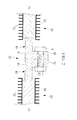
- FIG. 6A and 6B As a conventional example employing heat exchange between the outside air and the coolant, specific examples of each piece of equipment releasing heat are illustrated in Figs. 6A and 6B .
- reference sign 1 in the figure designates a wind power generator
- 2 designates a tower
- 3 designates a nacelle
- 4 designates a rotor head
- 5 designates wind-turbine blades
- 6 designates a nacelle air inlet
- 7 designates an air outlet.
- Fig. 6B is an enlarged view of relevant portions of a wall surface structure of the nacelle 3.
- the nacelle wall surface of the general nacelle structure has an outside wall structure that is formed by connecting a plurality of separated wall members 3a, which are made of fiber reinforced plastic (hereinafter referred to as "FRP"), and a structure in which flange parts 3b provided inside the nacelle are connected with bolts and nuts 8 is employed.
- FRP fiber reinforced plastic
- cooling of a main bearing 9 and a gear box 10, which constitute mechanical transmission devices is achieved by using lubricating oil, which circulates through a lubricating oil circulatory system, as the coolant for heat exchange with the outside air.
- lubricating oil which circulates through a lubricating oil circulatory system
- heat exchange between the lubricating oil and the outside air is performed in an oil cooler 11, and lubrication and cooling of frictional heat are achieved by supplying the lubricating oil that has been cooled due to the heat absorption with the outside air to rotating parts.
- antifreeze is used as the coolant for heat exchange with the outside air
- primary air is used as the coolant for heat exchange with the outside air.
- continuous cooling is achieved by supplying and circulating the antifreeze or the primary air, whose heat has been absorbed by the outside air, to electrical apparatuses that are heat sources to be coaled.
- Reference sign 14 in this figure designates a transformer.
- the above-described outside air flows into the nacelle 3 through the nacelle air inlet 6 by operating a fan 15.
- This outside air flows within the nacelle 3 to exchange heat with various types of coolants, and to ventilate and cool the inside of the nacelle, and after that, the outside air flows out through the air outlet 7.
- the following PTL 1 discloses a wind power generator that is provided with heat dissipating fins for dissipating heat to the outside air from a rotor hub through a cover.
- the solar constant (the amount of incoming solar energy per unit area incident on the surface of the earth's atmosphere perpendicularly) is about 1370 W/m 2 , and thus, by assuming that the top surface and the side surfaces of the nacelle 3 form a substantially cuboid shape having a heat receiving area of 80 m 2 (nacelle height of 4 m, nacelle width of 4 m, and nacelle length of 5 m), the amount of heat input to the wall surface of the nacelle 3 from the sun will be about 77 kW at an atmospheric transmittance of 0.7.
- the total heat loss in the wind power generator 1 when the heat loss in the wind power generator 1 is assumed to be about 10 to 15% of the generated output power, with the wind power generator 1 having a rated generated output power of 2500 kW, the total heat loss will be about 250 to 375 kW. Adding the amount of heat input from the sunlight to this total heat loss, the required cooling capacity in the nacelle 3 is increased to about 327 to 452 kW. That is to say, by adding the amount of heat input from the sunlight, the total heat loss from the nacelle 3 will be increased to 120 to 131% relative to the total heat loss without taking the sunlight into consideration.
- the thermal insulance of the FRP becomes the dominant factor, and therefore, the effect of the heat input from the sunlight can be negligible in many cases.
- the air temperature in the nacelle 3 will exceed the upper limit of the electronic equipment environmental temperature. Because the lifetime of the electronic equipment installed inside the nacelle 3 is shortened, such a temperature environment in the nacelle 3 is undesirable.
- the nacelle 3 of the wind power generator 1 by making the plate thickness of the wall surface thinner, the heat-dissipation resistance is reduced to improve the heat dissipation performance.
- the amount of heat input into the nacelle 3 from the sunlight is increased. Therefore, particularly during daytime in summer, because the air temperature of the nacelle 3 tends to exceed the upper environmental temperature limit of the electronic equipment, which causes the lifetime of the electronic equipment to be shortened, as in the case where the plate thickness is thick, it is undesirable for the wall surface of the nacelle 3 to have a small plate thickness.
- the input-heat resistance and the heat-dissipation resistance of the wall surface are in an inverse relationship, and therefore, it is difficult to optimize the plate thickness of the nacelle wall surface, such that only the heat dissipation performance through the wall surface of the nacelle 3 from the inside of the nacelle 3 to the outside air is improved in order to maintain a suitable air temperature in the nacelle 3.
- the present invention has been conceived in light of the circumstances described above, and an object thereof is to provide a wind power generator in which the amount of heat that is input into a nacelle from outside the nacelle due to the solar radiation is suppressed, and in which the heat dissipation performance from the inside of the nacelle to the outside air is improved.
- a wind power generator according to the present invention is a wind power generator in which a driving mechanism and power generation mechanism linked with a rotor head, to which wind-turbine blades are attached, are accommodated and installed in a nacelle, wherein an outer wall surface of the nacelle is provided with, on at least a part of the wall surface where no direct sunlight is radiated, a heat-dissipation-resistance reducing portion that uses a member having a higher thermal conductivity than that of a peripheral wall member.
- the outer wall surface of the nacelle is provided with, on at least a part of the wall surface where no direct sunlight is radiated, the heat-dissipation-resistance reducing portion that uses the member having a higher thermal conductivity than that of peripheral wall member, the peripheral wall member where direct sunlight is radiated has a relatively low thermal conductivity, and thus, it is possible to suppress the amount of heat input to the nacelle, and at the same time, because the heat-dissipation-resistance reducing portion where no direct sunlight is radiated has a relatively high thermal conductivity, only the heat dissipation performance from the inside of the nacelle to the outside air is improved.
- the heat-dissipation-resistance reducing portion is installed at a location (bottom surface etc.) where no direct sunlight is radiated, even if a member having a high thermal conductivity is used, the amount of heat input into the nacelle due to the solar heat will not be increased, and it is possible to efficiently dissipate the heat inside the nacelle to the outside air through the high-thermal-conductive member.
- the heat-dissipation-resistance reducing portion may be provided with a fin that is attached on at least one of the surfaces, and thereby, the heat dissipation performance can be improved furthermore.
- the heat-dissipation-resistance reducing portion may be provided with heat transport means that is linked with a heat source installed in the nacelle and carries heat therebetween, and thereby, heat can be dissipated efficiently from a high-temperature heat source to the outside air.
- the heat-dissipation-resistance reducing portion may be formed into a wave-like shape, and thereby, it is possible to ensure necessary rigidities even if the plate thickness of the member is made thinner in order to save weight, and at the same time, it is possible to increase the heat transporting surface area to the outside air.
- the present invention described above by providing a heat-dissipation-resistance reducing portion on an outer wall surface of a nacelle, it is possible to reduce the amount of heat input to the nacelle from the outside of the nacelle due to solar radiation, and to improve the heat dissipation performance from the inside of the nacelle to the outside air. Therefore, the air temperature inside the nacelle is maintained so as not to exceed the upper environmental temperature limit of the electronic equipment by suppressing the temperature rise even in an operating state where the amount of heat input from the sunlight is high, for example, during a sunny day in summer. Accordingly, the electronic equipment installed in the nacelle can be operated under a suitable temperature environment that dose not exceed the upper environmental temperature limit of the electronic equipment, and thus, reliability and durability are improved to achieve long lifetime.
- the temperature rise of the internal air in the nacelle is suppressed, for example, it is possible to reduce the capacity of heat exchanger that cools the coolant, such as lubricating oil, antifreeze, primary air, and so forth, with the outside air. Because such a reduction in size of the heat exchanger is also effective for reducing the amount of outside air required for the heat exchange, it is possible to reduce the power of an electric motor required for driving the fan that introduces the outside air, and to improve the power generating efficiency of the wind power generator as a whole.
- the coolant such as lubricating oil, antifreeze, primary air, and so forth
- a wind power generator 1A includes a tower 2 erected upright on a base, a nacelle 30 provided at the top of the tower 2, and a rotor head 4 provided on the nacelle 30 so as to be rotatable about a substantially horizontal axis.
- a plurality of (for example three) wind-turbine blades 5 are attached to the rotor head 4 in a radiating pattern around a rotational axis thereof. Accordingly, the force of wind striking the wind turbine blades 5 from the rotational axis direction of the rotor head 4 is converted to a motive force that causes the rotor head 4 to rotate about its rotational axis.
- the illustrated wind power generator 1A is of a so-called upwind type in which the wind-turbine blades 5 rotate in front of the nacelle 30.
- the type of the wind power generator 1A is not limited thereto, and, for instance, the present invention described below can be applied to a downwind type.
- a main bearing 9 and a gear box 10 are provided as a mechanical-driving-force transmitting mechanism that transmits the rotation of the rotor head 4 to a generator 13. Furthermore, an inverter control panel 12, a transformer 14 that transform the electric power generated by the generator 13, and so forth are installed in the nacelle, 30 as various types of electrical apparatuses that constitute a power generation mechanism with the generator 13.
- a driving mechanism / power generation mechanism which are linked to the rotor head 4, to :which the wind-turbine blades 5 are attached, are accommodated and installed inside the nacelle 30.
- driving / power generation mechanisms include equipment that generates heat while operating.
- the nacelle 30 is a hollow member having a substantially cuboid form, in which a cover member 31 covers around a nacelle base plate and frame components (not shown).
- the cover member 31 is, for example, a plate-like member made of a fiber reinforced plastic (FRP), and this cover member 31 forms the outer wall of the nacelle 30.
- a nacelle air inlet 6 formed in the cover member 31 is provided at the bottom of the front end face of the nacelle 30 for introducing the outside air into the nacelle 30 for cooling.
- a filter having salt removal and dust removal functions is attached to this nacelle air inlet 6.
- an air outlet 7 having a rain guard attached to the opening of the cover member 31 is provided in the top surface of the nacelle 30.
- the outside air that is introduced through the nacelle air inlet 6 by the operation of a fan 15 is used for heat exchange etc. with a coolant that cools heat-releasing equipment installed inside the nacelle 30, thereafter, the warmed outside air is discharged top the atmosphere from the air outlet 7.
- an oil cooler 11 that uses the lubricating oil of the main bearing 9 and the gear box 10 as the coolant and that achieves cooling by heat exchange between the lubricating oil and the outside air is illustrated.
- the actual nacelle 30 is provided with various types of heat exchangers (not shown) in order to perform heat exchange between the outside air and the coolant that are used for cooling the inverter control panel 12, the generator 13, and so forth.
- An arrow Ca in the figure shows an example of the main flow of outside air. The actual flow of the outside air flows so as to circulate within the nacelle 30 depending on the arrangement etc. of the heat exchangers installed in the nacelle 30.
- the outer wall surface of such a nacelle 30 is provided with, on at least a part of the wall surface where no direct sunlight is radiated, a heat-dissipation-resistance reducing portion 50 formed of a member (high-thermal-conductivity member) having a higher thermal conductivity than that of a peripheral wall member.
- the wall surface where no direct sunlight is radiated includes, for example, a bottom surface portion (a lower surface towards the tower 2) 32 having a substantially cuboid form.
- the structure is formed by connecting a plurality of separate cover members 31 that form the outer wall surface of the nacelle 30.
- the heat-dissipation-resistance reducing portion 50 formed of a high-thermal-conductive member is provided on bottom-surface cover members 40 that is attached to the bottom surface portion 32.
- This heat-dissipation-resistance reducing portion 50 is desirably provided over the largest possible region on the bottom surface portion 32, excluding the connection part to the tower 2.
- Fig. 1B is a bottom view showing the bottom surface of the nacelle 30 from the aground (view taken along arrow A in Fig. 1A ).
- the bottom-surface cover members 40 attached to the bottom surface portion 32 are provided with, on a central portion excluding a peripheral frame 41, the heat-dissipation-resistance reducing portion 50 formed of the high-thermal-conductive member.
- the heat-dissipation-resistance reducing portion 50 has a non-separated monolithic structure, for instance, a multi-part separated structure may be formed by forming a frame within the peripheral frame 41 etc.
- the illustrated bottom surface portion 32 has a structure in which a plurality of separated cover members 40 are connected, one integral cover member 40 may be used depending on the size of the nacelle 30 etc.
- Fig. 2 is a sectional view of relevant portions showing a cross-sectional structure (cross-section along B-B in Fig. 1B ) of a connection part in the bottom surface portion 32 formed by connecting a plurality of bottom-surface cover members 40.
- These bottom-surface cover members 40 are each provided with the heat-dissipation-resistance reducing portion 50 that is held at the inner side of the peripheral frame 41 made of FRP and a flange parts 42 that are provided by bending the end portion of the peripheral frame 41 towards the inside of the nacelle 30.
- the flange parts 42 are used in the connecting part between the adjacent bottom-surface cover members 40 or between the adjacent cover members 31, for connecting and integrating them with nuts and bolts 8.
- the above-described heat-dissipation-resistance reducing portion 50 is provided with a member having a higher thermal conductivity than a peripheral wall member made of FRP etc. on the outer wall surface of the nacelle 30 where no direct sunlight is radiated.
- a metal plate 51 may be held in the central portion of the peripheral frame 41 by impregnating the metal plate 51 having a high thermal conductivity in the peripheral frame 41 made of FRP, and curing it.
- the metal whose thermal conductivity is higher than that of the FRP of the peripheral wall member includes, for example, copper, aluminium, duralumin, and so forth.
- no limitation is imposed on its material so long as it is more thermally conductive and lighter than the peripheral wall member.
- the high-thermal-conductive member that is impregnated in the bottom-surface cover member 40 made of FRP is not limited to the above-described metal plate 51, and for example, high-thermal-conductive resin (for example, epoxy resin etc.) may be employed.
- the high-thermal-conductive resin in this case includes, for example, those made to have a thermal conductivity close to that of high-thermal-conductive metal by impregnating high-thermal-conductive fibers, such as glass fibers, carbon, and so forth, into, for example, epoxy resin etc., and at the same time, by increasing the number of connecting points between the fibers compared with general fiber-reinforced plastic.
- the thermal conductivity of the heat-dissipation-resistance reducing portion 50 is high, the thermal insulance is reduced in the wall surface in which the bottom-surface cover members 40 are installed. That is to say, the thermal conductivity of the peripheral wall member made of FRP etc., where direct sunlight is radiated, becomes relatively low, and at the same time, the thermal conductivity of the heat-dissipation-resistance reducing portion 50, where no direct sunlight is radiated, becomes relatively high.
- the outer wall surface of the nacelle 30 is provided with the heat-dissipation-resistance reducing portion 50 that has a higher thermal conductivity than the peripheral wall member on at least a part of the outer wall surface, where no direct sunlight is radiated, as in, for example, the bottom surface portion 32.
- the nacelle wall surface made of FRP etc. it is possible to suppress the amount of heat input to the nacelle 30 due to solar radiation, and at the same time, with the heat-dissipation-resistance reducing portion 50, where no sunlight is radiated, regardless of the high thermal conductivity, because no direct sunlight is radiated thereon, the amount of heat input due to the sunlight is small, and only the heat dissipation performance from the inside of the nacelle 30 to the outside air is improved.
- the heat-dissipation-resistance reducing portion 50 is installed at the location where no direct sunlight is radiated, as in the bottom surface portion 32, the amount of solar heat input to the nacelle 30 does not increase even if a member having a high thermal conductivity is used; therefor, it is possible to dissipate the heat to the outside air efficiently from the inside of the nacelle 30 through the high-thermal-conductive member that is installed as the heat-dissipation-resistance reducing portion 50.
- the above-described heat-dissipation-resistance reducing portion 50 of the wind power generator 1 is preferably provided with fins 52 on at least one side thereof.
- These fins 52 improve the heat dissipation performance by increasing the contact surface area with the air inside the nacelle 30 and with the outside air, and are attached so as to protrude from the surface of the high-thermal-conductivity member, such as the above-mentioned metal plate 51 etc.
- such fins 52 may be attached on only one side of the heat-dissipation-resistance reducing portion 50, that is either the side in contact with the air inside the nacelle 30 or the side in contact with the outside air, in a more preferable embodiment, as show in Fig. 2 , it is preferable to improve the heat dissipation performance even more by providing the fins 52 on both sides of the heat-dissipation-resistance reducing portion 50.
- a heat-dissipation-resistance reducing portion 50A is provided with a heat transport member 53 that is joined to the heat source, such as the gear box 10 etc., installed in the nacelle 30, and that guides and carries the heat from the high-temperature side to the low-temperature side.
- this is a configuration example in which heat is transported from the high-temperature heat source that is installed in the nacelle 30 to the metal plate 51 of the heat-dissipation-resistance reducing portion 50A provided on the outer wall surface of the nacelle 30 through the heat transport member 53, and the heat is dissipated from the surface of the high-thermal-conductivity member, such as the metal plate 51 etc., to the outside air, which is the low-temperature side.
- the fins 52 are attached only on the outside-airside surface of the high-thermal-conductivity member such as the metal plate 51 etc.; however the configuration is not limited thereto.
- the heat-dissipation-resistance reducing portion 50A may be provided over the whole bottom surface portion 32 or on at least a part thereof.
- thermo bond that transports heat by directly connecting the heat source and the high-thermal-conductivity member, such as the metal plate 51 etc., with a metal with high thermal conductivity, such as, for example, copper, aluminium, duralumin, and so forth; a heat pipe that uses a fluid as an intermediate medium; and so forth.
- the heat source in the nacelle 30 is assumed to be the gear box 10, regarding the heat source of high-temperature, it may apply to other high-temperature heat sources, such as, for example, windings in the generator 13, coils in the transformer 14s, and so forth.
- a second modification of the above-described wind power generator 1A will be explained with reference to Fig. 5 . Parts similar to those in the above-described embodiment are assigned the same reference numerals, and a detailed description thereof will be omitted.
- the thin plate is suitably made of a material that is light and that has a high thermal conductivity, such as copper, aluminum, duralumin, high-thermal-conductive resin, and so forth, as described above.
- this plate By using this plate by forming it into a wave-like shape, it is possible to ensure the necessary rigidity even if a plate-like member having a small plate thickness is used for weight saving.
- the heat-dissipation-resistance reducing portion 50B formed into the wave-like shape has a larger surface area: therefore, it is possible to improve the heat dissipation with the increased heat transporting surface area that dissipates the heat to the outside air.
- the heat-dissipation-resistance reducing portion 50B having the wave-like shape can not only ensure rigidity and achieve weight saving, but can also improve heat dissipation with the increased heat transporting surface area.
- the heat-dissipation-resistance reducing portion 50B may be attached so as to cover either all of the above-described bottom-plate cover member 40 or a part thereof.
- the heat-dissipation-resistance reducing portion 50 on the outer wall surface of the nacelle 30, it is possible to suppress the amount of heat input into the nacelle 30 from the outside of the nacelle due to solar radiation, and to improve the heat dissipation performance from the inside of the nacelle 30 to the outside air.
- the air temperature inside the nacelle 30 is maintained so as not to exceed the upper environmental temperature limit of the electronic equipment by suppressing the temperature rise even in an operating state where the amount of heat input from the sunlight is increased, for example, during a sunny day in summer. Therefore, various types of electronic equipment that are installed in the nacelle 30 are operated under a suitable temperature environment that does not exceed the upper environmental temperature limit of the electronic equipment, and thus, their reliability and durability are improved.
- heat-dissipation-resistance reducing portion 50 may also be installed at suitable locations, such as the cover member of the rotor head 4.
- suitable locations such as the cover member of the rotor head 4.
Abstract
Provided is a wind power generator that reduces the amount of heat input into a nacelle from the outside of the nacelle due to the solar radiation, and that improves the heat dissipation performance from the inside of the nacelle to the outside air. In a wind power generator (1A) in which a driving mechanism and power generation mechanism that are connected with a rotor head (4), to which wind-turbine blades (5) are attached, are accommodated and installed in a nacelle (30), an outer wall surface of the nacelle (30) is provided with, on at least a part of the wall surface where no direct sunlight is radiated, a heat-dissipation-resistance reducing portion (50) that uses a member having a higher thermal conductivity than that of a peripheral wall member.
Description
- The present invention relates to a wind power generator that generates electricity upon receiving wind force on wind-turbine blades, and in particular, to cooling of equipment installed in a nacelle of a wind power generator.
- A wind power generator (hereinafter referred to as "wind turbine") is a device in which a rotor head equipped with wind-turbine blades rotates upon receiving wind force, and in which a generator driven by, for example, accelerating this rotation with a gear box generates electricity.
The above-described rotor head is attached at an end portion of a nacelle, which is generally installed on top of a wind turbine tower (hereinafter referred to as "tower") in a manner that allows yawing, and is supported so as to be rotatable about a substantially horizontal lateral rotation axis. - As a general device configuration, a device for transmitting a mechanical rotational force that is received from the wind-turbine blades and a power generator are installed inside the nacelle of the wind power generator. Among those, the rotational-force transmission device is provided with a main bearing and a gear box, and the power generator is provided with a generator, a transformer, an inverter, and a control panel, or is provided with a generator and a control panel.
Such equipment in the nacelle is cooled by using outside air that is sucked in through a nacelle air inlet, performing heat exchange between the outside air and a coolant with individual heat exchangers, which are installed on each piece of equipment serving as a heat source, and supplying the coolant, whose heat has been absorbed by the outside air, to the equipment to be cooled. In this case, the outside air to be sucked into the nacelle is generally subjected to salt removal treatment and dust removal treatment through a filter. - As a conventional example employing heat exchange between the outside air and the coolant, specific examples of each piece of equipment releasing heat are illustrated in
Figs. 6A and 6B . InFigs. 6A and 6B ,reference sign 1 in the figure designates a wind power generator, 2 designates a tower, 3 designates a nacelle, 4 designates a rotor head, 5 designates wind-turbine blades, 6 designates a nacelle air inlet, and 7 designates an air outlet.
In addition,Fig. 6B is an enlarged view of relevant portions of a wall surface structure of thenacelle 3. The nacelle wall surface of the general nacelle structure has an outside wall structure that is formed by connecting a plurality ofseparated wall members 3a, which are made of fiber reinforced plastic (hereinafter referred to as "FRP"), and a structure in whichflange parts 3b provided inside the nacelle are connected with bolts andnuts 8 is employed. - With such a
wind power generator 1, cooling of a main bearing 9 and agear box 10, which constitute mechanical transmission devices, is achieved by using lubricating oil, which circulates through a lubricating oil circulatory system, as the coolant for heat exchange with the outside air. In this case, heat exchange between the lubricating oil and the outside air is performed in anoil cooler 11, and lubrication and cooling of frictional heat are achieved by supplying the lubricating oil that has been cooled due to the heat absorption with the outside air to rotating parts. - On the other hand, for cooling the electrical apparatuses that are heat releasing sources, for instance, in the case of an
inverter control panel 12, antifreeze is used as the coolant for heat exchange with the outside air, and in the case of agenerator 13, primary air is used as the coolant for heat exchange with the outside air. In both case, continuous cooling is achieved by supplying and circulating the antifreeze or the primary air, whose heat has been absorbed by the outside air, to electrical apparatuses that are heat sources to be coaled.Reference sign 14 in this figure designates a transformer. - The above-described outside air flows into the
nacelle 3 through thenacelle air inlet 6 by operating afan 15. This outside air flows within thenacelle 3 to exchange heat with various types of coolants, and to ventilate and cool the inside of the nacelle, and after that, the outside air flows out through theair outlet 7.
In addition, the followingPTL 1 discloses a wind power generator that is provided with heat dissipating fins for dissipating heat to the outside air from a rotor hub through a cover. - {PTL 1} Japanese Unexamined Patent Application, Publication No.
2009-091929 - Is the above-described
wind power generator 1, if a summer day temperature (for instance, 40 °C) is set as the most severe outside air temperature condition through the year, because the upper environmental temperature limit of general electronic equipment is about 50 °C, the temperature difference between the inside and the outside of thenacelle 3 is required to be controlled within 10 °C or less.
To describe this more specifically, the solar constant (the amount of incoming solar energy per unit area incident on the surface of the earth's atmosphere perpendicularly) is about 1370 W/m2, and thus, by assuming that the top surface and the side surfaces of thenacelle 3 form a substantially cuboid shape having a heat receiving area of 80 m2 (nacelle height of 4 m, nacelle width of 4 m, and nacelle length of 5 m), the amount of heat input to the wall surface of thenacelle 3 from the sun will be about 77 kW at an atmospheric transmittance of 0.7. - On the other hand, when the heat loss in the
wind power generator 1 is assumed to be about 10 to 15% of the generated output power, with thewind power generator 1 having a rated generated output power of 2500 kW, the total heat loss will be about 250 to 375 kW. Adding the amount of heat input from the sunlight to this total heat loss, the required cooling capacity in thenacelle 3 is increased to about 327 to 452 kW. That is to say, by adding the amount of heat input from the sunlight, the total heat loss from thenacelle 3 will be increased to 120 to 131% relative to the total heat loss without taking the sunlight into consideration. - In general, when the wall surface of the
nacelle 3 is made of FRP, because the thickness of the wall surface (plate thickness) is as much as about 100 mm, the thermal insulance of the FRP becomes the dominant factor, and therefore, the effect of the heat input from the sunlight can be negligible in many cases.
On the other hand, the larger the wall surface thermal insulance of thenacelle 3 is, the lower the heat-dissipation resistance through the wall surface of thenacelle 3 becomes, and therefore, the larger the temperature difference between the air in thenacelle 3 and the outside air becomes. In particular, during daytime in the summer when the effect of the solar heat is large, there is a risk that the air temperature in thenacelle 3 will exceed the upper limit of the electronic equipment environmental temperature. Because the lifetime of the electronic equipment installed inside thenacelle 3 is shortened, such a temperature environment in thenacelle 3 is undesirable. - That is to say, with the
nacelle 3 of thewind power generator 1, by making the plate thickness of the wall surface thinner, the heat-dissipation resistance is reduced to improve the heat dissipation performance. However, because this makes the input-heat resistance of the wall surface smaller at the same time, the amount of heat input into thenacelle 3 from the sunlight is increased. Therefore, particularly during daytime in summer, because the air temperature of thenacelle 3 tends to exceed the upper environmental temperature limit of the electronic equipment, which causes the lifetime of the electronic equipment to be shortened, as in the case where the plate thickness is thick, it is undesirable for the wall surface of thenacelle 3 to have a small plate thickness. - As described above, in the
nacelle 3 of thewind power generator 1, the input-heat resistance and the heat-dissipation resistance of the wall surface are in an inverse relationship, and therefore, it is difficult to optimize the plate thickness of the nacelle wall surface, such that only the heat dissipation performance through the wall surface of thenacelle 3 from the inside of thenacelle 3 to the outside air is improved in order to maintain a suitable air temperature in thenacelle 3.
The present invention has been conceived in light of the circumstances described above, and an object thereof is to provide a wind power generator in which the amount of heat that is input into a nacelle from outside the nacelle due to the solar radiation is suppressed, and in which the heat dissipation performance from the inside of the nacelle to the outside air is improved. - In order to solve the problems described above, the present invention employs the following solutions.
A wind power generator according to the present invention is a wind power generator in which a driving mechanism and power generation mechanism linked with a rotor head, to which wind-turbine blades are attached, are accommodated and installed in a nacelle, wherein an outer wall surface of the nacelle is provided with, on at least a part of the wall surface where no direct sunlight is radiated, a heat-dissipation-resistance reducing portion that uses a member having a higher thermal conductivity than that of a peripheral wall member. - According to such a wind power generator, because the outer wall surface of the nacelle is provided with, on at least a part of the wall surface where no direct sunlight is radiated, the heat-dissipation-resistance reducing portion that uses the member having a higher thermal conductivity than that of peripheral wall member, the peripheral wall member where direct sunlight is radiated has a relatively low thermal conductivity, and thus, it is possible to suppress the amount of heat input to the nacelle, and at the same time, because the heat-dissipation-resistance reducing portion where no direct sunlight is radiated has a relatively high thermal conductivity, only the heat dissipation performance from the inside of the nacelle to the outside air is improved. That is to say, because the heat-dissipation-resistance reducing portion is installed at a location (bottom surface etc.) where no direct sunlight is radiated, even if a member having a high thermal conductivity is used, the amount of heat input into the nacelle due to the solar heat will not be increased, and it is possible to efficiently dissipate the heat inside the nacelle to the outside air through the high-thermal-conductive member.
- In the above-mentioned wind power generator, the heat-dissipation-resistance reducing portion may be provided with a fin that is attached on at least one of the surfaces, and thereby, the heat dissipation performance can be improved furthermore.
- In the above-mentioned wind power generator, the heat-dissipation-resistance reducing portion may be provided with heat transport means that is linked with a heat source installed in the nacelle and carries heat therebetween, and thereby, heat can be dissipated efficiently from a high-temperature heat source to the outside air.
- In the above-mentioned wind power generator, the heat-dissipation-resistance reducing portion may be formed into a wave-like shape, and thereby, it is possible to ensure necessary rigidities even if the plate thickness of the member is made thinner in order to save weight, and at the same time, it is possible to increase the heat transporting surface area to the outside air.
- According to the present invention described above, by providing a heat-dissipation-resistance reducing portion on an outer wall surface of a nacelle, it is possible to reduce the amount of heat input to the nacelle from the outside of the nacelle due to solar radiation, and to improve the heat dissipation performance from the inside of the nacelle to the outside air. Therefore, the air temperature inside the nacelle is maintained so as not to exceed the upper environmental temperature limit of the electronic equipment by suppressing the temperature rise even in an operating state where the amount of heat input from the sunlight is high, for example, during a sunny day in summer. Accordingly, the electronic equipment installed in the nacelle can be operated under a suitable temperature environment that dose not exceed the upper environmental temperature limit of the electronic equipment, and thus, reliability and durability are improved to achieve long lifetime.
- In addition, because the temperature rise of the internal air in the nacelle is suppressed, for example, it is possible to reduce the capacity of heat exchanger that cools the coolant, such as lubricating oil, antifreeze, primary air, and so forth, with the outside air. Because such a reduction in size of the heat exchanger is also effective for reducing the amount of outside air required for the heat exchange, it is possible to reduce the power of an electric motor required for driving the fan that introduces the outside air, and to improve the power generating efficiency of the wind power generator as a whole.
-
- {
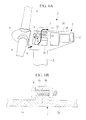
FIG. 1A} FIG. 1A is a view showing an embodiment of a wind power generator according to the present invention, and is a sectional view of relevant portions showing, in outline, an example internal configuration of a nacelle. - {
FIG. 1B} FIG. 1B is a view showing an embodiment of a wind power generator according to the present invention, and is a view taken along arrow A inFig. 1A . - {
FIG. 2} FIG. 2 is a sectional view taken along B-B inFig. 1B (the wall surface cross-sectional structure of the nacelle). - {
FIG. 3} FIG. 3 is a sectional view of relevant portions showing, in outline, an example internal configuration of a nacelle as a first modification of a wind power generator according to the present invention. - {
FIG. 4} FIG. 4 is a sectional view showing the wall surface cross-sectional structure of a nacelle in the wind power generator shown inFig. 3 . - {
FIG. 5} FIG. 5 is a sectional view of relevant portions showing, in outline, an example internal configuration of a nacelle as a second modification of a wind power generator according to the present invention. - {
FIG. 6A} FIG. 6A is a view showing a conventional example related to internal cooling of a nacelle of a wind power generator, and is a sectional view of relevant portions showing, in outline, an example internal configuration of the nacelle. - (
FIG. 6B} FIG. 6B is a view showing a conventional example related to internal cooling of a nacelle of a wind power generator, and is a sectional view showing an example wall surface cross-sectional structure of a nacelle. - An embodiment of a wind power generator according to the present invention will be described below with reference to the drawings.
InFig. 1A a wind power generator 1A includes atower 2 erected upright on a base, anacelle 30 provided at the top of thetower 2, and arotor head 4 provided on thenacelle 30 so as to be rotatable about a substantially horizontal axis.
A plurality of (for example three) wind-turbine blades 5 are attached to therotor head 4 in a radiating pattern around a rotational axis thereof. Accordingly, the force of wind striking thewind turbine blades 5 from the rotational axis direction of therotor head 4 is converted to a motive force that causes therotor head 4 to rotate about its rotational axis. The illustrated wind power generator 1A is of a so-called upwind type in which the wind-turbine blades 5 rotate in front of thenacelle 30. However, the type of the wind power generator 1A is not limited thereto, and, for instance, the present invention described below can be applied to a downwind type. - In the
nacelle 30, amain bearing 9 and agear box 10 are provided as a mechanical-driving-force transmitting mechanism that transmits the rotation of therotor head 4 to agenerator 13. Furthermore, aninverter control panel 12, atransformer 14 that transform the electric power generated by thegenerator 13, and so forth are installed in the nacelle, 30 as various types of electrical apparatuses that constitute a power generation mechanism with thegenerator 13.
In this way, in the wind power generator 1A, a driving mechanism / power generation mechanism, which are linked to therotor head 4, to :which the wind-turbine blades 5 are attached, are accommodated and installed inside thenacelle 30. Such driving / power generation mechanisms include equipment that generates heat while operating. - The
nacelle 30 is a hollow member having a substantially cuboid form, in which acover member 31 covers around a nacelle base plate and frame components (not shown). Thecover member 31 is, for example, a plate-like member made of a fiber reinforced plastic (FRP), and thiscover member 31 forms the outer wall of thenacelle 30.
Anacelle air inlet 6 formed in thecover member 31 is provided at the bottom of the front end face of thenacelle 30 for introducing the outside air into thenacelle 30 for cooling. A filter having salt removal and dust removal functions is attached to thisnacelle air inlet 6. In addition, in order to allow the cooling outside air that has been circulated inside thenacelle 30 to flow out to the atmosphere, anair outlet 7 having a rain guard attached to the opening of thecover member 31 is provided in the top surface of thenacelle 30. - The outside air that is introduced through the
nacelle air inlet 6 by the operation of afan 15 is used for heat exchange etc. with a coolant that cools heat-releasing equipment installed inside thenacelle 30, thereafter, the warmed outside air is discharged top the atmosphere from theair outlet 7.
In the illustrated example configuration, an oil cooler 11 that uses the lubricating oil of themain bearing 9 and thegear box 10 as the coolant and that achieves cooling by heat exchange between the lubricating oil and the outside air is illustrated. However, as described in the Background Art, theactual nacelle 30 is provided with various types of heat exchangers (not shown) in order to perform heat exchange between the outside air and the coolant that are used for cooling theinverter control panel 12, thegenerator 13, and so forth.
An arrow Ca in the figure shows an example of the main flow of outside air. The actual flow of the outside air flows so as to circulate within thenacelle 30 depending on the arrangement etc. of the heat exchangers installed in thenacelle 30. - The outer wall surface of such a
nacelle 30 is provided with, on at least a part of the wall surface where no direct sunlight is radiated, a heat-dissipation-resistance reducing portion 50 formed of a member (high-thermal-conductivity member) having a higher thermal conductivity than that of a peripheral wall member. In the outer wall surface of thenacelle 30, the wall surface where no direct sunlight is radiated includes, for example, a bottom surface portion (a lower surface towards the tower 2) 32 having a substantially cuboid form.
In the illustrated example, the structure is formed by connecting a plurality ofseparate cover members 31 that form the outer wall surface of thenacelle 30. The heat-dissipation-resistance reducing portion 50 formed of a high-thermal-conductive member is provided on bottom-surface cover members 40 that is attached to thebottom surface portion 32. This heat-dissipation-resistance reducing portion 50 is desirably provided over the largest possible region on thebottom surface portion 32, excluding the connection part to thetower 2. -
Fig. 1B is a bottom view showing the bottom surface of thenacelle 30 from the aground (view taken along arrow A inFig. 1A ). In the figure, the bottom-surface cover members 40 attached to thebottom surface portion 32 are provided with, on a central portion excluding aperipheral frame 41, the heat-dissipation-resistance reducing portion 50 formed of the high-thermal-conductive member. In this case, although the heat-dissipation-resistance reducing portion 50 has a non-separated monolithic structure, for instance, a multi-part separated structure may be formed by forming a frame within theperipheral frame 41 etc.
Although the illustratedbottom surface portion 32 has a structure in which a plurality of separatedcover members 40 are connected, oneintegral cover member 40 may be used depending on the size of thenacelle 30 etc. -
Fig. 2 is a sectional view of relevant portions showing a cross-sectional structure (cross-section along B-B inFig. 1B ) of a connection part in thebottom surface portion 32 formed by connecting a plurality of bottom-surface cover members 40. These bottom-surface cover members 40 are each provided with the heat-dissipation-resistance reducing portion 50 that is held at the inner side of theperipheral frame 41 made of FRP and aflange parts 42 that are provided by bending the end portion of theperipheral frame 41 towards the inside of thenacelle 30. Theflange parts 42 are used in the connecting part between the adjacent bottom-surface cover members 40 or between theadjacent cover members 31, for connecting and integrating them with nuts andbolts 8. - The above-described heat-dissipation-
resistance reducing portion 50 will be explained in detail below.
The heat-dissipation-resistance reducing portion 50 is provided with a member having a higher thermal conductivity than a peripheral wall member made of FRP etc. on the outer wall surface of thenacelle 30 where no direct sunlight is radiated. For example, ametal plate 51 may be held in the central portion of theperipheral frame 41 by impregnating themetal plate 51 having a high thermal conductivity in theperipheral frame 41 made of FRP, and curing it.
In this case, the metal whose thermal conductivity is higher than that of the FRP of the peripheral wall member includes, for example, copper, aluminium, duralumin, and so forth. However, no limitation is imposed on its material so long as it is more thermally conductive and lighter than the peripheral wall member. - In addition, the high-thermal-conductive member that is impregnated in the bottom-
surface cover member 40 made of FRP is not limited to the above-describedmetal plate 51, and for example, high-thermal-conductive resin (for example, epoxy resin etc.) may be employed. The high-thermal-conductive resin in this case includes, for example, those made to have a thermal conductivity close to that of high-thermal-conductive metal by impregnating high-thermal-conductive fibers, such as glass fibers, carbon, and so forth, into, for example, epoxy resin etc., and at the same time, by increasing the number of connecting points between the fibers compared with general fiber-reinforced plastic. - As described above, by employing the bottom-
surface cover members 40 that are provided with the heat-dissipation-resistance reducing portion 50 on the nacelle outer wall surface where no direct sunlight is radiated, because the thermal conductivity of the heat-dissipation-resistance reducing portion 50 is high, the thermal insulance is reduced in the wall surface in which the bottom-surface cover members 40 are installed. That is to say, the thermal conductivity of the peripheral wall member made of FRP etc., where direct sunlight is radiated, becomes relatively low, and at the same time, the thermal conductivity of the heat-dissipation-resistance reducing portion 50, where no direct sunlight is radiated, becomes relatively high. This is because the outer wall surface of thenacelle 30 is provided with the heat-dissipation-resistance reducing portion 50 that has a higher thermal conductivity than the peripheral wall member on at least a part of the outer wall surface, where no direct sunlight is radiated, as in, for example, thebottom surface portion 32. In addition, in order to improve the heat dissipation performance, it is generally preferred to orientate the fibers in the FRP such that the thermal conductivity is higher in the thickness-wise direction. - Accordingly, in the nacelle wall surface made of FRP etc., it is possible to suppress the amount of heat input to the
nacelle 30 due to solar radiation, and at the same time, with the heat-dissipation-resistance reducing portion 50, where no sunlight is radiated, regardless of the high thermal conductivity, because no direct sunlight is radiated thereon, the amount of heat input due to the sunlight is small, and only the heat dissipation performance from the inside of thenacelle 30 to the outside air is improved.
In other words, because the heat-dissipation-resistance reducing portion 50 is installed at the location where no direct sunlight is radiated, as in thebottom surface portion 32, the amount of solar heat input to thenacelle 30 does not increase even if a member having a high thermal conductivity is used; therefor, it is possible to dissipate the heat to the outside air efficiently from the inside of thenacelle 30 through the high-thermal-conductive member that is installed as the heat-dissipation-resistance reducing portion 50. - In addition, the above-described heat-dissipation-
resistance reducing portion 50 of thewind power generator 1 is preferably provided withfins 52 on at least one side thereof. Thesefins 52 improve the heat dissipation performance by increasing the contact surface area with the air inside thenacelle 30 and with the outside air, and are attached so as to protrude from the surface of the high-thermal-conductivity member, such as the above-mentionedmetal plate 51 etc.
Althoughsuch fins 52 may be attached on only one side of the heat-dissipation-resistance reducing portion 50, that is either the side in contact with the air inside thenacelle 30 or the side in contact with the outside air, in a more preferable embodiment, as show inFig. 2 , it is preferable to improve the heat dissipation performance even more by providing thefins 52 on both sides of the heat-dissipation-resistance reducing portion 50. - Next, a first modification of the above-described wind power generator 1A will be explained with reference to
Figs. 3 and4 . Parts similar to those in the above-described embodiment are assigned the same reference numerals, and a detailed description thereof will be omitted.
In thewind power generator 1B in the first modification, a heat-dissipation-resistance reducing portion 50A is provided with aheat transport member 53 that is joined to the heat source, such as thegear box 10 etc., installed in thenacelle 30, and that guides and carries the heat from the high-temperature side to the low-temperature side. That is to say, this is a configuration example in which heat is transported from the high-temperature heat source that is installed in thenacelle 30 to themetal plate 51 of the heat-dissipation-resistance reducing portion 50A provided on the outer wall surface of thenacelle 30 through theheat transport member 53, and the heat is dissipated from the surface of the high-thermal-conductivity member, such as themetal plate 51 etc., to the outside air, which is the low-temperature side. In this case, thefins 52 are attached only on the outside-airside surface of the high-thermal-conductivity member such as themetal plate 51 etc.; however the configuration is not limited thereto. The heat-dissipation-resistance reducing portion 50A may be provided over the wholebottom surface portion 32 or on at least a part thereof. - As suitable specific examples of the above-described
heat transport member 53, it is effective to use: a thermal bond that transports heat by directly connecting the heat source and the high-thermal-conductivity member, such as themetal plate 51 etc., with a metal with high thermal conductivity, such as, for example, copper, aluminium, duralumin, and so forth; a heat pipe that uses a fluid as an intermediate medium; and so forth.
By employing such a configuration, because theheat transport member 53 transports the heat directly from the high-temperature heat source in thenacelle 30 to the outside air, which is a low-heat source, without passing through the air in thenacelle 30, the heat dissipation efficiency from the inside of thenacelle 30 to the outside air is improved further.
In the above-described description, although the heat source in thenacelle 30 is assumed to be thegear box 10, regarding the heat source of high-temperature, it may apply to other high-temperature heat sources, such as, for example, windings in thegenerator 13, coils in the transformer 14s, and so forth. - Next, a second modification of the above-described wind power generator 1A will be explained with reference to
Fig. 5 . Parts similar to those in the above-described embodiment are assigned the same reference numerals, and a detailed description thereof will be omitted.
In thewind power generator 1C in the second modification, a thin plate with high thermal conductivity, which is formed to have a wave-like shape, is used as the heat-dissipation-resistance reducing portion 50B. In this case, the thin plate is suitably made of a material that is light and that has a high thermal conductivity, such as copper, aluminum, duralumin, high-thermal-conductive resin, and so forth, as described above. By using this plate by forming it into a wave-like shape, it is possible to ensure the necessary rigidity even if a plate-like member having a small plate thickness is used for weight saving.
In addition, the heat-dissipation-resistance reducing portion 50B formed into the wave-like shape has a larger surface area: therefore, it is possible to improve the heat dissipation with the increased heat transporting surface area that dissipates the heat to the outside air. - As described above, the heat-dissipation-
resistance reducing portion 50B having the wave-like shape can not only ensure rigidity and achieve weight saving, but can also improve heat dissipation with the increased heat transporting surface area.
In this case, the heat-dissipation-resistance reducing portion 50B may be attached so as to cover either all of the above-described bottom-plate cover member 40 or a part thereof. - As described above, according to the wind power generator in the above-described embodiment and modifications, by providing the heat-dissipation-
resistance reducing portion 50 on the outer wall surface of thenacelle 30, it is possible to suppress the amount of heat input into thenacelle 30 from the outside of the nacelle due to solar radiation, and to improve the heat dissipation performance from the inside of thenacelle 30 to the outside air. As a result, the air temperature inside thenacelle 30 is maintained so as not to exceed the upper environmental temperature limit of the electronic equipment by suppressing the temperature rise even in an operating state where the amount of heat input from the sunlight is increased, for example, during a sunny day in summer.
Therefore, various types of electronic equipment that are installed in thenacelle 30 are operated under a suitable temperature environment that does not exceed the upper environmental temperature limit of the electronic equipment, and thus, their reliability and durability are improved. - In addition, by suppressing the temperature rise of the air in the
nacelle 30, for example, it is possible to reduce the capacities of the heat exchangers that cool the coolant with the outside air, as with theoil cooler 11 that cools the lubricating oil with the outside air. That is to say, because the temperature of the outside air that is introduced into thenacelle 30 and used for heat exchange is lowered, it is possible to reduce the capacity of the heat exchanger by an amount corresponding to the increase in heat absorption capacity of the outside air.
Because such a size reduction of the heat exchanger is also effective for reducing the amount of outside air required for heat exchange, it is possible to reduce the power of an electric motor required for driving thefan 15 that introduces the outside air, and to improve the power generating efficiency of the wind power generator as a whole. - In addition, the above-described heat-dissipation-
resistance reducing portion 50 may also be installed at suitable locations, such as the cover member of therotor head 4.
Note that, the present invention is not limited to the above-described embodiment, and appropriate modifications are permissible within a range that does not depart from the spirit of the present invention. -
- 1A, 1B, 1C wind power generator
- 3, 30 nacelle
- 4 rotor head
- 5 wind-turbine blade
- 6 nacelle air inlet
- 7 air outlet
- 9 main bearing
- 10 gear box
- 11 oil cooler
- 12 inverter control panel
- 13 generator
- 14 transformer
- 15 fan
- 31 cover member
- 32 bottom surface portion
- 40 bottom-surface cover member
- 41 peripheral frame
- 42 flange part
- 50, 50A, 50B heat-dissipation-resistance reducing portion
- 51 metal plate
- 52 fin
- 53 heat transport member
Claims (4)
- A wind power generator in which a driving mechanism and power generation mechanism linked with a rotor head, to which wind-turbine blades are attached, are accommodated and installed in a nacelle,
wherein an outer wall surface of the nacelle is provided with, on at least a part of the wall surface where no direct sunlight is radiated, a heat-dissipation-resistance reducing portion that uses a member having a higher thermal conductivity than that of a peripheral wall member. - A wind power generator according to Claim 1, wherein the heat-dissipation-resistance reducing portion is provided with a fin that is attached on at least one of the surfaces.
- A wind power generator according to Claim 1, wherein the heat-dissipation-resistance reducing portion is provided with heat transport means that is linked with a heat source installed in the nacelle and carries heat therebetween.
- A wind power generator according to Claim 1, wherein the heat-dissipation-resistance reducing portion is formed into a wave-like shape.
Applications Claiming Priority (2)
| Application Number | Priority Date | Filing Date | Title |
|---|---|---|---|
| JP2010149098A JP2012012980A (en) | 2010-06-30 | 2010-06-30 | Wind power generator |
| PCT/JP2011/061739 WO2012002066A1 (en) | 2010-06-30 | 2011-05-23 | Wind-powered electricity generator |
Publications (1)
| Publication Number | Publication Date |
|---|---|
| EP2589801A1 true EP2589801A1 (en) | 2013-05-08 |
Family
ID=45401800
Family Applications (1)
| Application Number | Title | Priority Date | Filing Date |
|---|---|---|---|
| EP11800535.4A Withdrawn EP2589801A1 (en) | 2010-06-30 | 2011-05-23 | Wind-powered electricity generator |
Country Status (3)
| Country | Link |
|---|---|
| EP (1) | EP2589801A1 (en) |
| JP (1) | JP2012012980A (en) |
| WO (1) | WO2012002066A1 (en) |
Families Citing this family (5)
| Publication number | Priority date | Publication date | Assignee | Title |
|---|---|---|---|---|
| KR101391763B1 (en) | 2012-10-10 | 2014-05-27 | 한국해양과학기술원 | Tidal Current Power Nacelle with Heat Radiating Stiffener |
| KR101434443B1 (en) * | 2012-12-27 | 2014-08-28 | 삼성중공업 주식회사 | Apparatus for nacelle air cooling using by heat exchanger |
| JP2014204647A (en) * | 2013-04-10 | 2014-10-27 | 株式会社日立製作所 | Rotary electric machine or wind generator system |
| JP6118185B2 (en) * | 2013-06-12 | 2017-04-19 | 株式会社日立製作所 | Rotating electric machine and wind power generation system equipped with rotating electric machine |
| JP6356500B2 (en) * | 2014-06-19 | 2018-07-11 | 株式会社日立製作所 | Wind power generator |
Family Cites Families (4)
| Publication number | Priority date | Publication date | Assignee | Title |
|---|---|---|---|---|
| JP3989693B2 (en) * | 2000-04-28 | 2007-10-10 | 三菱電機株式会社 | Wind power generator |
| DE10124268B4 (en) * | 2001-05-18 | 2006-02-09 | Wobben, Aloys, Dipl.-Ing. | generator cooling |
| US20090232659A1 (en) * | 2008-03-11 | 2009-09-17 | Joris Schiffer | Concrete to fabricate the nacelle of a wind turbine |
| WO2009126696A1 (en) * | 2008-04-08 | 2009-10-15 | Ufo Wind Llc | Wind-driven generation of power |
-
2010
- 2010-06-30 JP JP2010149098A patent/JP2012012980A/en not_active Ceased
-
2011
- 2011-05-23 EP EP11800535.4A patent/EP2589801A1/en not_active Withdrawn
- 2011-05-23 WO PCT/JP2011/061739 patent/WO2012002066A1/en active Application Filing
Also Published As
| Publication number | Publication date |
|---|---|
| JP2012012980A (en) | 2012-01-19 |
| WO2012002066A1 (en) | 2012-01-05 |
Similar Documents
| Publication | Publication Date | Title |
|---|---|---|
| US8403638B2 (en) | Wind power generator | |
| EP2182619B1 (en) | Arrangement for cooling of an electrical machine | |
| EP2376778B1 (en) | Wind turbine comprising a cooling circuit | |
| US8058742B2 (en) | Thermal management system for wind turbine | |
| EP2163761B1 (en) | Wind turbine comprising a heating and cooling system | |
| EP2527650B1 (en) | System to cool the nacelle and the heat generating components of an offshore wind turbine | |
| US8585358B2 (en) | Wind turbine generator including air-cooled heat exchanger | |
| US20150233265A1 (en) | Integrated cooling system for a nacelle of a wind turbine | |
| EP2589801A1 (en) | Wind-powered electricity generator | |
| US8308438B2 (en) | Wind power generator | |
| TWI382125B (en) | Wind power generation | |
| US9410532B2 (en) | Cooling arrangement | |
| US10590916B2 (en) | Multisiphon passive cooling system | |
| CN218506110U (en) | Power device, propeller and water area movable equipment | |
| EP2589802A1 (en) | Wind power generation apparatus | |
| KR101434443B1 (en) | Apparatus for nacelle air cooling using by heat exchanger | |
| CN217976461U (en) | Wind power recovery power generation system | |
| CN220646112U (en) | Cooling device of wind turbine generator | |
| CN116221044A (en) | Wind power cabin heat abstractor of coupling helicopter platform | |
| EP2950430B1 (en) | Electrical machine system and wind power generating system | |
| KR101638867B1 (en) | Wind turbine comprising integrated cooling system for the heat generating component inside the nacelle assembly. | |
| CN114450765A (en) | Heat exchanger assembly for dry-type transformer | |
| JP2012012978A (en) | Wind power generator |
Legal Events
| Date | Code | Title | Description |
|---|---|---|---|
| PUAI | Public reference made under article 153(3) epc to a published international application that has entered the european phase |
Free format text: ORIGINAL CODE: 0009012 |
|
| 17P | Request for examination filed |
Effective date: 20121128 |
|
| AK | Designated contracting states |
Kind code of ref document: A1 Designated state(s): AL AT BE BG CH CY CZ DE DK EE ES FI FR GB GR HR HU IE IS IT LI LT LU LV MC MK MT NL NO PL PT RO RS SE SI SK SM TR |
|
| DAX | Request for extension of the european patent (deleted) | ||
| STAA | Information on the status of an ep patent application or granted ep patent |
Free format text: STATUS: THE APPLICATION HAS BEEN WITHDRAWN |
|
| 18W | Application withdrawn |
Effective date: 20141006 |