EP2572562B1 - Set-top box having dissipating thermal loads - Google Patents
Set-top box having dissipating thermal loads Download PDFInfo
- Publication number
- EP2572562B1 EP2572562B1 EP11724317.0A EP11724317A EP2572562B1 EP 2572562 B1 EP2572562 B1 EP 2572562B1 EP 11724317 A EP11724317 A EP 11724317A EP 2572562 B1 EP2572562 B1 EP 2572562B1
- Authority
- EP
- European Patent Office
- Prior art keywords
- heatsink
- circuit board
- electronic device
- vent
- heat source
- Prior art date
- Legal status (The legal status is an assumption and is not a legal conclusion. Google has not performed a legal analysis and makes no representation as to the accuracy of the status listed.)
- Not-in-force
Links
Images

Classifications
-
- H—ELECTRICITY
- H05—ELECTRIC TECHNIQUES NOT OTHERWISE PROVIDED FOR
- H05K—PRINTED CIRCUITS; CASINGS OR CONSTRUCTIONAL DETAILS OF ELECTRIC APPARATUS; MANUFACTURE OF ASSEMBLAGES OF ELECTRICAL COMPONENTS
- H05K7/00—Constructional details common to different types of electric apparatus
- H05K7/20—Modifications to facilitate cooling, ventilating, or heating
- H05K7/2039—Modifications to facilitate cooling, ventilating, or heating characterised by the heat transfer by conduction from the heat generating element to a dissipating body
- H05K7/20409—Outer radiating structures on heat dissipating housings, e.g. fins integrated with the housing
-
- H—ELECTRICITY
- H01—ELECTRIC ELEMENTS
- H01L—SEMICONDUCTOR DEVICES NOT COVERED BY CLASS H10
- H01L23/00—Details of semiconductor or other solid state devices
- H01L23/34—Arrangements for cooling, heating, ventilating or temperature compensation ; Temperature sensing arrangements
- H01L23/36—Selection of materials, or shaping, to facilitate cooling or heating, e.g. heatsinks
- H01L23/367—Cooling facilitated by shape of device
- H01L23/3677—Wire-like or pin-like cooling fins or heat sinks
-
- H—ELECTRICITY
- H05—ELECTRIC TECHNIQUES NOT OTHERWISE PROVIDED FOR
- H05K—PRINTED CIRCUITS; CASINGS OR CONSTRUCTIONAL DETAILS OF ELECTRIC APPARATUS; MANUFACTURE OF ASSEMBLAGES OF ELECTRICAL COMPONENTS
- H05K7/00—Constructional details common to different types of electric apparatus
- H05K7/20—Modifications to facilitate cooling, ventilating, or heating
- H05K7/2039—Modifications to facilitate cooling, ventilating, or heating characterised by the heat transfer by conduction from the heat generating element to a dissipating body
- H05K7/20436—Inner thermal coupling elements in heat dissipating housings, e.g. protrusions or depressions integrally formed in the housing
- H05K7/20445—Inner thermal coupling elements in heat dissipating housings, e.g. protrusions or depressions integrally formed in the housing the coupling element being an additional piece, e.g. thermal standoff
-
- H—ELECTRICITY
- H01—ELECTRIC ELEMENTS
- H01L—SEMICONDUCTOR DEVICES NOT COVERED BY CLASS H10
- H01L2924/00—Indexing scheme for arrangements or methods for connecting or disconnecting semiconductor or solid-state bodies as covered by H01L24/00
- H01L2924/0001—Technical content checked by a classifier
- H01L2924/0002—Not covered by any one of groups H01L24/00, H01L24/00 and H01L2224/00
Definitions
- the present invention relates to quiet set-top boxes having improved heat dissipating capabilities.
- US2005128710 discloses a cooling system for an electronic system housing a heat-generating component, the system comprises a housing having a first vertical outer wall with a first vent and a second vertical outer wall with a second vent; a circuit board having a first heat source element and a second heat source element; a contoured heatsink in thermal engagement with the first heat source element, wherein the contoured heatsink overlies at least one-third of the circuit board and extends along a first vertical side wall; a second heatsink contacting the second heat source element, wherein the second heatsink is located in only one half of the housing and is aligned with the second vent; wherein the second heat source element is arranged on the second heat source element.
- US6049469 relates to a electromagnetic shielding and a heat dissipation for a computer system wherein a second heat source element is arranged below a circuit board and the circuit board do not has heat passage via holes therethrough over the second heat source element.
- Set-top boxes continue to be in high demand and an ever increasing need exists to reduce the size and improve aesthetic appeal, performance, functionality, and robustness of these devices and the like. As such, many set-top boxes now require smartcard readers, hard drives, and other heat generating elements.
- An electronic device comprises a housing having a first vertical outer wall with a first vent and a second vertical outer wall with a second vent; a circuit board having a first heat source element and a second heat source element; a contoured heatsink in thermal engagement with the first heat source element, wherein the contoured heatsink overlies at least one-third of the circuit board and extends along the first vertical side wall; and a second heatsink contacting the second heat source element, wherein the second heatsink is located in only one half of the device and is aligned with the second vent.
- the contoured heatsink can have a planar peripheral portion and a central depression portion in which the planar peripheral portion completely or partially surrounds the central depression portion and the central depression portion contacts the first heat source element.
- the contoured heatsink substantially overlies the circuit board and completely overlies the second heatsink.
- the second heatsink can be a finned heatsink or the second heatsink can be a contoured heatsink having a second planar peripheral portion and a second central depression in which the second planar peripheral portion surrounds at least a portion of the second central depression portion, and the second central depression portion contacts the second heat source element.
- the device can comprise a frame that has a base and embosses, wherein the base is under the circuit board and the embosses contact and support the circuit board.
- the frame can have at least a first vertical side wall oriented along the first vertical outer wall and a second vertical side wall oriented along the second vertical outer wall in which the first vertical side wall has a first interior vent aligned with the first vent and the second vertical side wall has a second interior vent aligned with the second vent.
- the second heat source element can be a smart card reader and can be below the circuit board, wherein the circuit board can have heat passage via holes therethrough over the second heat source element and under the second heatsink where it contacts the circuit board or a thermal pad thereon.
- the invention is directed to arrangements for cooling an electronic assembly that generates a thermal load, for example a smart card reader, when the electronic assembly is disposed in a hostile thermal environment.
- a hostile thermal environment is one in which there is insufficient ventilation for adequate cooling, for example, a densely populated electronic box such as a set-top box, wherein desired design criteria are directed to compact, sleek designs with small footprints. Providing for sufficient cooling to dissipate thermal loads in such a set-top box is challenging under any circumstances.
- the cooling problem is exacerbated by including in a set- top box a low profile smart card reader that generates its own thermal load and that is mounted on the bottom side of a multilayer printed circuit board (PCB) disposed inside the set-top box. Dissipating the thermal load of the smart card reader is even more difficult due to a mounting location at the bottom of the set-top box, beneath a multilayer PCB on which are mounted other electronic components generating other thermal loads, and far removed from the top of the set-top box. With respect to conventional wisdom, placing the smart card reader in such a location is quite counter-intuitive.
- PCB printed circuit board
- An electronic assembly such as a smart card reader can be safely positioned in a hostile thermal environment as described above, in accordance with the inventive arrangements taught herein.
- the smart card reader contacts are located on the bottom of the smart card reader and push the smart card upward against the bottom printed circuit board surface. Since the card surface is in direct contact with the printed circuit board, a patch or area of many copper-plated thru-hole vias is advantageously added in the board at the location of the smart card contacts. Other highly thermally conductive metal can be used to plate the vias.
- a thermally conductive pad is advantageously placed on the patch of vias and a heat sink is advantageously placed on the pad.
- a top broad heat sink has proved to be an effective way to cool the main integrated circuit of the set-top box, but the smart card reader adds an additional thermal load that may not be dissipated by the conventional top broad heat sink.
- a finned convecting heat sink 58 advantageously radiates heat through convection to vents on the outer sides 34 of the outer cover 28 of a set-top box 1.
- the first embodiment can be appreciated by particular reference to Figs. 1- 4 .
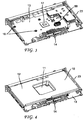
- Fig. 1 shows an internal view of the set-top box 1 in an assembled form with a front portion of the set-top box removed according to the first embodiment.
- Fig. 1 shows a top broad heat sink 10, which is an internal component.
- the top broad heat sink 10 can be a generally contoured plate that has a generally planar periphery 12 and a contoured central feature such as a pocket, central depression, notch, recess, multilevel depression, or mesa extending from and/or into a plane of the planar periphery.
- the central feature or central depression 11 can have side walls extending from the planar periphery and form an obtuse angle therewith.
- the contoured feature can have a flat bottom designed to contact the main integrated circuit and/or other heat generating component 17 on a main printed circuit board 13 which can be below it.
- Fig. 1 further shows a main printed circuit board 13 or the like, which can be generally flat.
- the main printed circuit board 13 can have a main integrated circuit 17 or the like in a central region and holes for mounting and/or securing the main printed circuit board 13 to a frame pan 18.
- the main integrated circuit and other heat generating or hot components 17 can contact the flat bottom or other portion of the central depression 11 of the top broad heat sink 10, which can be in thermal contact with the other heat generating or hot components through a thermal joint 27 which could be a pad.
- the main printed circuit board 13 is shown being mounted and/or secured to embosses 20 of the frame pan 18 by use of screws, bolts or solder pad joints 43 through the holes or contact points in the circuit board 13, wherein the main printed circuit board 13 is effectively contacting the frame pan 18. This contact can be thermal contact.
- Fig. 2 shows a perspective view of the underside of the main printed main printed circuit board 13 or the like.
- the main printed circuit board 13 can have in a central region of holes and associated pins 16 for primary or additional mounting and/or securing the main printed circuit board 13 to a frame pan 18.
- Other features of the main printed circuit board are shown in the figure which can include jack panel connectors 15 at one edge and a button cluster 14 at another edge. These edges can be opposing edges.
- Fig. 2 shows how the smart card reader 61 can be positioned on the main printed circuit board 13.
- Fig. 3 shows another perspective view of the upper side of the main printed main printed circuit board 13 or the like in contact with the frame 18.
- Fig. 3 shows the main printed circuit board 13 can have main integrated circuit or other heat generating component 17 in a central region and holes and associated pins 16 for mounting and/or securing the main printed circuit board 13 to a frame pan 18. Additionally shown is the finned convecting heat sink 58.
- the finned convecting heat sink 58 is constructed of 24 fins in which there are four rows of flat evenly spaced fins with the planar portion oriented along the x-axis (or the long axis which is parallel to the front of the set-top box) and in which there are six columns of evenly spaced fins oriented along the y-axis (or short axis which is parallel to the sides of the set-top box).
- the finned convecting heat sink 58 having a long dimension in the x-axis being 17.78 mm, a short dimension in the y-axis being 10.18 mm, and a height being 10.11 mm. Keeping these dimensions within 20% of the stated dimensions can be effective.
- the gaps between the fins are U-shaped or V-shaped in which the depths of the gaps are greater than half the height of the finned convecting heat sink 58.
- Fig. 4 shows a perspective view of the top broad heat sink 10 on the main printed main printed circuit board 13.
- the top broad heat sink 10 substantially covers the main printed main printed circuit board 13.
- Fig. 1 further shows how the smart card reader 61 can be in contact with the main printed circuit board 13 and immediately thereunder.
- the smart card reader 61 is shown having a smart card 64 inserted therein through a smart card entrance port 63 in one of the outer sides 34.
- the smart card reader 61 is shown being in contact with at least one thermal pad joint 62 that conducts heat generated by the smart card reader 61 to the finned convecting heat sink 58 which is also in contact with the main printed circuit board 13 and positioned immediately thereon.
- heat via holes 65 are shown being in the a main printed circuit board 13 to permit the heat from the smart card reader 61 to propagate to the finned convecting heat sink 58.
- the heat via holes 65 can be copper plated and the population of the heat via holes can be located substantially along and over the perimeter of the smart card reader 61 and uniformly distributed over the smart card reader 61 to optimize heat transfer from the smart card reader 61. It is advantageous to have the total plan view area of the via holes exceeding one-half area the plan view area of the via hole region, which is the region where the finned convecting heat sink 58 or the second heat sink contacts circuit board or the thermal pad joint.
- the vias can have vertical walls and can have an aspect ratio, which is a width or diameter of the via hole to height ratio, of 0.5 to 10.
- the set-top box 1 in Fig. 1 can have an outer cover 28 that further includes an upper wall 31, lower wall 32, and multiple outer sides 34.
- the exterior side of the lower wall 32 can include rubber feet 33 which can be at least 6 mm in height to ensure adequate air entry under the set-top box for improved thermal management.
- Fig. 1 also shows at least one proximal vent 59 in one of the outer sides 34 which is positioned in the general proximity of the finned convecting heat sink 58. It is preferable that the proximal vent 59 be positioned in one of the vertical outer sides 34 at a place that is closest to the finned convecting heat sink 58. At least one general vent 60 is shown which can be at other locations on other outer sides 34. The general vents 60 can further assist with the dissipation of heat. Additionally, the frame pan 18 can have side walls 23 that have complementary vents 66 which can be aligned with the vents of the outer sides 34. Having the vents on the outer sides in the combination of top broad heat sink 10 and the finned convecting heat sink 58 eliminates or can eliminate the need for vents in the upper wall 31.
- Fig. 1 further shows outer gaps 41 between the side walls 23 of the frame pan 18 and the outer side 34 of the outer cover 28; inner gaps 40 between the edge of the planar periphery 12 of the top broad heat sink 12 and the side walls 23 of the frame pan 18; bottom gap 42 between the lower wall 32 of the outer cover 28 and the base 22 of the frame pan 18; and upper gap 44 between the upper wall 31 of the outer cover 28 and the planar periphery 12 of the top broad heat sink 10.
- the bottom gap 42 and upper gap 44 prevent the outer cover 28 from overheating.
- a patch or area of many copper-plated thru-hole vias is advantageously added in the board at the location of the smart card contacts.
- a thermally conductive pad is advantageously placed on the patch of vias 62 and a heat sink is advantageously placed on the pad.
- a top broad heat sink has proved to be an effective way to cool the main integrated circuit of the set-top box, but the smart card reader adds an additional thermal load that cannot be dissipated by the conventional top broad heat sink.
- the finned heat sink and proximal vents have enhanced the thermal management of the set-top box.
- the top broad radiating heat sink is advantageously split or divided into two parts or two separate heat sinks.
- One of the two parts is in thermal contact with the main integrated circuit in the set-top box.
- the other of the two parts is in thermal contact with the smart card through the patch or area of vias.
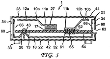
- Fig. 5 shows an internal view of the set-top box 1 in an assembled form with a front portion of the set-top box removed according to the second embodiment.
- Fig. 5 shows first top broad heat sink 10a, which is an internal component.
- the top broad heat sink 10a can be a generally contoured plate that has a generally planar periphery 12a and a contoured central feature such as a pocket, central depression, notch, recess, multilevel depression, or mesa extending from and/or into a plane of the planar periphery, wherein the planar periphery 12a preferably only surrounds part of the or central depression 11a.
- the planar periphery 12a surrounds 3 sides of the central depression 11a.
- the central feature or central depression 11a can have side walls extending from the planar periphery and form an obtuse angle therewith.
- the contoured feature can have a flat bottom designed to contact the main integrated circuit and/or other heat generating component 17 on a main printed circuit board 13 which can be below it.
- Fig. 5 also shows the second top broad heat sink 10b, which is an internal component.
- the top broad heat sink 10b can also be a generally contoured plate that has a generally planar periphery 12b and a contoured central feature such as a pocket, central depression, notch, recess, multilevel depression, mesa extending from and/or into a plane of the planar periphery, wherein the planar periphery 12b preferably only surrounds part of the central depression 11b.
- the planar periphery 12b surrounds 3 sides of the central depression 11b.
- the central feature or central depression 11b can have side walls extending from the planar periphery and form an obtuse angle therewith.
- the contoured feature can have a flat bottom designed to contact the main printed circuit board 13 in the region where the smart card reader 61 is located.
- the smart card reader 61 is shown being in contact with at least one thermal pad joint 62 that conducts heat generated by the smart card reader 61 to the second top broad heat sink 10b which is also in contact with the main printed circuit board 13 and thereon.
- heat transmissive via holes 65 are positioned in the main printed circuit board 13 to permit the heat from the smart card reader 61 to propagate to the second top broad heat sink 10b.
- the heat via holes 65 can be copper plated and the population of the heat via holes can be located substantially along the perimeter of the smart card reader 61 and uniformly distributed over the smart card reader 61 to optimize heat transfer from the smart card reader 61.
- the vias can have the same characteristics and dimensional aspects in this embodiment as in the first embodiment.
- the main printed circuit board 13, frame pan 18 and the outer cover 28 are generally the same as in the first embodiment of the invention.
- the frame pan 18 also can have complementary vents 66 which can be aligned with the vents 60 of the outer sides 34, wherein the edges of planar peripheries 12a, 12b run along the outer sides 34.
- the invention is applicable to computers and other electronic devices having heat generating components. Furthermore, the invention is also applicable to electronic parts other than circuit boards which can generate heat.
- the invention is not limited to the precise arrangements and instrumentalities shown. As such, the invention is intended to apply, for example, to heat source elements such as hard drives, smart card readers, integrated circuits, and light sources that could be used to light buttons. Further, when a heatsink is said to be contacting a heat source element, this can imply through direct contact or contact through an intermediary component such as via holes and/or thermal pads or thermal joints.
- vent can imply a single vent opening or multiple localized vent openings; the expression “substantially overlying” is intended to mean completely overlying or overlying at 90% of a surface of a structure; the expression “planar peripheral portion” can mean that the portion is completely planar or can include portions which are generally planar, but may have some raised portions or groves which may be needed to add structural integrity or may be needed to accommodate components in the set-top box.
Landscapes
- Engineering & Computer Science (AREA)
- Physics & Mathematics (AREA)
- Microelectronics & Electronic Packaging (AREA)
- Chemical & Material Sciences (AREA)
- Materials Engineering (AREA)
- Condensed Matter Physics & Semiconductors (AREA)
- General Physics & Mathematics (AREA)
- Computer Hardware Design (AREA)
- Power Engineering (AREA)
- Thermal Sciences (AREA)
- Cooling Or The Like Of Electrical Apparatus (AREA)
- Cooling Or The Like Of Semiconductors Or Solid State Devices (AREA)
Description
- The present invention relates to quiet set-top boxes having improved heat dissipating capabilities.
-
US2005128710 discloses a cooling system for an electronic system housing a heat-generating component, the system comprises a housing having a first vertical outer wall with a first vent and a second vertical outer wall with a second vent;a circuit board having a first heat source element and a second heat source element; a contoured heatsink in thermal engagement with the first heat source element, wherein the contoured heatsink overlies at least one-third of the circuit board and extends along a first vertical side wall; a second heatsink contacting the second heat source element, wherein the second heatsink is located in only one half of the housing and is aligned with the second vent; wherein the second heat source element is arranged on the second heat source element. -
US6049469 relates to a electromagnetic shielding and a heat dissipation for a computer system wherein a second heat source element is arranged below a circuit board and the circuit board do not has heat passage via holes therethrough over the second heat source element. Set-top boxes continue to be in high demand and an ever increasing need exists to reduce the size and improve aesthetic appeal, performance, functionality, and robustness of these devices and the like. As such, many set-top boxes now require smartcard readers, hard drives, and other heat generating elements. - Particular problems that such set-top boxes face are damage due to heat generation. However, a need exists for a means for dissipating heat without creating other complications such as noticeable noise or large spacial or footprint requirements. As such, heat dissipation fans, which tend to improve electrical robustness of the set-top boxes, are not preferable, because they do introduce noise and increase the size of set-top boxes. Also, other set-top box designs having vents on the top of the set-top boxes surprisingly require more internal free space (i.e., a larger outer casing) when there are no fans employed to appropriately dissipate heat. Additionally, these top vent systems place the set-top box in jeopardy of damage due to liquid spills.
- In light of the requirement for set-top boxes to appropriately dissipate heat and yet also house more electronic components and meet customer preferences, a need exists for a new set-top box design that has improved heat dissipating capabilities.
- An electronic device according to
claim 1 is provided, said electronic device comprises a housing having a first vertical outer wall with a first vent and a second vertical outer wall with a second vent; a circuit board having a first heat source element and a second heat source element; a contoured heatsink in thermal engagement with the first heat source element, wherein the contoured heatsink overlies at least one-third of the circuit board and extends along the first vertical side wall; and a second heatsink contacting the second heat source element, wherein the second heatsink is located in only one half of the device and is aligned with the second vent. The contoured heatsink can have a planar peripheral portion and a central depression portion in which the planar peripheral portion completely or partially surrounds the central depression portion and the central depression portion contacts the first heat source element. The contoured heatsink substantially overlies the circuit board and completely overlies the second heatsink. The second heatsink can be a finned heatsink or the second heatsink can be a contoured heatsink having a second planar peripheral portion and a second central depression in which the second planar peripheral portion surrounds at least a portion of the second central depression portion, and the second central depression portion contacts the second heat source element. If the second heatsink is a contoured heatsink, then the contoured heatsink can overlie less than half the circuit board and the second heatsink can overlie more than one-third of the circuit board. The device can comprise a frame that has a base and embosses, wherein the base is under the circuit board and the embosses contact and support the circuit board. The frame can have at least a first vertical side wall oriented along the first vertical outer wall and a second vertical side wall oriented along the second vertical outer wall in which the first vertical side wall has a first interior vent aligned with the first vent and the second vertical side wall has a second interior vent aligned with the second vent. The second heat source element can be a smart card reader and can be below the circuit board, wherein the circuit board can have heat passage via holes therethrough over the second heat source element and under the second heatsink where it contacts the circuit board or a thermal pad thereon. - The invention will now be described by way of example with reference to the accompanying figures of which:
-
Fig. 1 shows a cross sectional interior view of the assembled set-top box according to a first embodiment of the invention with a front portion of the set-top box removed; -
Fig. 2 shows a perspective view of the underside of the main printed circuit board according to the invention; -
Fig. 3 shows a perspective view of the upper side of the main printed circuit board according to the invention; -
Fig. 4 shows a perspective view of the top broad heat sink on the main printed main printed circuit board according to a first embodiment of the invention; and -
Fig. 5 shows a cross sectional interior view of the assembled set-top box according to a second embodiment of the invention with a front portion of the set-top box removed. - The invention is directed to arrangements for cooling an electronic assembly that generates a thermal load, for example a smart card reader, when the electronic assembly is disposed in a hostile thermal environment. A hostile thermal environment is one in which there is insufficient ventilation for adequate cooling, for example, a densely populated electronic box such as a set-top box, wherein desired design criteria are directed to compact, sleek designs with small footprints. Providing for sufficient cooling to dissipate thermal loads in such a set-top box is challenging under any circumstances.
- In the exemplary embodiments of the invention disclosed herein, the cooling problem is exacerbated by including in a set- top box a low profile smart card reader that generates its own thermal load and that is mounted on the bottom side of a multilayer printed circuit board (PCB) disposed inside the set-top box. Dissipating the thermal load of the smart card reader is even more difficult due to a mounting location at the bottom of the set-top box, beneath a multilayer PCB on which are mounted other electronic components generating other thermal loads, and far removed from the top of the set-top box. With respect to conventional wisdom, placing the smart card reader in such a location is quite counter-intuitive. However, placing the smart card reader in such a location does enable the implementation of a desirable sleek design without objectionable top vents or objectionable fans. It will be understood by those skilled in the art that, in many if not most cases, vents in a set-top box may not be altogether avoided.
- An electronic assembly such as a smart card reader can be safely positioned in a hostile thermal environment as described above, in accordance with the inventive arrangements taught herein. The smart card reader contacts are located on the bottom of the smart card reader and push the smart card upward against the bottom printed circuit board surface. Since the card surface is in direct contact with the printed circuit board, a patch or area of many copper-plated thru-hole vias is advantageously added in the board at the location of the smart card contacts. Other highly thermally conductive metal can be used to plate the vias. A thermally conductive pad is advantageously placed on the patch of vias and a heat sink is advantageously placed on the pad. A top broad heat sink has proved to be an effective way to cool the main integrated circuit of the set-top box, but the smart card reader adds an additional thermal load that may not be dissipated by the conventional top broad heat sink.
- There are two exemplary embodiments taught herein and shown in the drawings for advantageously dissipating the thermal load generated by the smart card reader. In a first embodiment, a finned convecting
heat sink 58 advantageously radiates heat through convection to vents on theouter sides 34 of theouter cover 28 of a set-top box 1. The first embodiment can be appreciated by particular reference toFigs. 1- 4 . -
Fig. 1 shows an internal view of the set-top box 1 in an assembled form with a front portion of the set-top box removed according to the first embodiment.Fig. 1 shows a topbroad heat sink 10, which is an internal component. The topbroad heat sink 10 can be a generally contoured plate that has a generallyplanar periphery 12 and a contoured central feature such as a pocket, central depression, notch, recess, multilevel depression, or mesa extending from and/or into a plane of the planar periphery. The central feature orcentral depression 11 can have side walls extending from the planar periphery and form an obtuse angle therewith. The contoured feature can have a flat bottom designed to contact the main integrated circuit and/or otherheat generating component 17 on a main printedcircuit board 13 which can be below it. -
Fig. 1 further shows a main printedcircuit board 13 or the like, which can be generally flat. The main printedcircuit board 13 can have a main integratedcircuit 17 or the like in a central region and holes for mounting and/or securing the main printedcircuit board 13 to aframe pan 18. The main integrated circuit and other heat generating orhot components 17 can contact the flat bottom or other portion of thecentral depression 11 of the topbroad heat sink 10, which can be in thermal contact with the other heat generating or hot components through athermal joint 27 which could be a pad. The main printedcircuit board 13 is shown being mounted and/or secured to embosses 20 of theframe pan 18 by use of screws, bolts orsolder pad joints 43 through the holes or contact points in thecircuit board 13, wherein the main printedcircuit board 13 is effectively contacting theframe pan 18. This contact can be thermal contact. -
Fig. 2 shows a perspective view of the underside of the main printed main printedcircuit board 13 or the like. The main printedcircuit board 13 can have in a central region of holes and associatedpins 16 for primary or additional mounting and/or securing the main printedcircuit board 13 to aframe pan 18. Other features of the main printed circuit board are shown in the figure which can includejack panel connectors 15 at one edge and abutton cluster 14 at another edge. These edges can be opposing edges.Fig. 2 shows how thesmart card reader 61 can be positioned on the main printedcircuit board 13. -
Fig. 3 shows another perspective view of the upper side of the main printed main printedcircuit board 13 or the like in contact with theframe 18.Fig. 3 shows the main printedcircuit board 13 can have main integrated circuit or otherheat generating component 17 in a central region and holes and associatedpins 16 for mounting and/or securing the main printedcircuit board 13 to aframe pan 18. Additionally shown is the finned convectingheat sink 58. - In a particular example shown in
Fig. 3 , the finned convectingheat sink 58 is constructed of 24 fins in which there are four rows of flat evenly spaced fins with the planar portion oriented along the x-axis (or the long axis which is parallel to the front of the set-top box) and in which there are six columns of evenly spaced fins oriented along the y-axis (or short axis which is parallel to the sides of the set-top box). The finnedconvecting heat sink 58 having a long dimension in the x-axis being 17.78 mm, a short dimension in the y-axis being 10.18 mm, and a height being 10.11 mm. Keeping these dimensions within 20% of the stated dimensions can be effective. The gaps between the fins are U-shaped or V-shaped in which the depths of the gaps are greater than half the height of the finned convectingheat sink 58. -
Fig. 4 shows a perspective view of the topbroad heat sink 10 on the main printed main printedcircuit board 13. Here, one can see that the topbroad heat sink 10 substantially covers the main printed main printedcircuit board 13. - Regarding the
smart card reader 61,Fig. 1 further shows how thesmart card reader 61 can be in contact with the main printedcircuit board 13 and immediately thereunder. Thesmart card reader 61 is shown having asmart card 64 inserted therein through a smartcard entrance port 63 in one of the outer sides 34. Thesmart card reader 61 is shown being in contact with at least one thermal pad joint 62 that conducts heat generated by thesmart card reader 61 to the finned convectingheat sink 58 which is also in contact with the main printedcircuit board 13 and positioned immediately thereon. Here, heat viaholes 65 are shown being in the a main printedcircuit board 13 to permit the heat from thesmart card reader 61 to propagate to the finned convectingheat sink 58. The heat viaholes 65 can be copper plated and the population of the heat via holes can be located substantially along and over the perimeter of thesmart card reader 61 and uniformly distributed over thesmart card reader 61 to optimize heat transfer from thesmart card reader 61. It is advantageous to have the total plan view area of the via holes exceeding one-half area the plan view area of the via hole region, which is the region where the finned convectingheat sink 58 or the second heat sink contacts circuit board or the thermal pad joint. The vias can have vertical walls and can have an aspect ratio, which is a width or diameter of the via hole to height ratio, of 0.5 to 10. - Additionally, the set-
top box 1 inFig. 1 can have anouter cover 28 that further includes anupper wall 31,lower wall 32, and multipleouter sides 34. The exterior side of thelower wall 32 can includerubber feet 33 which can be at least 6 mm in height to ensure adequate air entry under the set-top box for improved thermal management. -
Fig. 1 also shows at least oneproximal vent 59 in one of theouter sides 34 which is positioned in the general proximity of the finned convectingheat sink 58. It is preferable that theproximal vent 59 be positioned in one of the verticalouter sides 34 at a place that is closest to the finned convectingheat sink 58. At least onegeneral vent 60 is shown which can be at other locations on otherouter sides 34. The general vents 60 can further assist with the dissipation of heat. Additionally, theframe pan 18 can haveside walls 23 that havecomplementary vents 66 which can be aligned with the vents of the outer sides 34. Having the vents on the outer sides in the combination of topbroad heat sink 10 and the finnedconvecting heat sink 58 eliminates or can eliminate the need for vents in theupper wall 31. -
Fig. 1 further showsouter gaps 41 between theside walls 23 of theframe pan 18 and theouter side 34 of theouter cover 28;inner gaps 40 between the edge of theplanar periphery 12 of the topbroad heat sink 12 and theside walls 23 of theframe pan 18;bottom gap 42 between thelower wall 32 of theouter cover 28 and thebase 22 of theframe pan 18; andupper gap 44 between theupper wall 31 of theouter cover 28 and theplanar periphery 12 of the topbroad heat sink 10. Thebottom gap 42 andupper gap 44 prevent theouter cover 28 from overheating. - Since the card surface is in direct contact with the printed circuit board, a patch or area of many copper-plated thru-hole vias is advantageously added in the board at the location of the smart card contacts. A thermally conductive pad is advantageously placed on the patch of
vias 62 and a heat sink is advantageously placed on the pad. A top broad heat sink has proved to be an effective way to cool the main integrated circuit of the set-top box, but the smart card reader adds an additional thermal load that cannot be dissipated by the conventional top broad heat sink. However, the finned heat sink and proximal vents have enhanced the thermal management of the set-top box. - In a second embodiment, the top broad radiating heat sink, previously embodied as a unitary heat sink, is advantageously split or divided into two parts or two separate heat sinks. One of the two parts is in thermal contact with the main integrated circuit in the set-top box. The other of the two parts is in thermal contact with the smart card through the patch or area of vias. The second embodiment can be appreciated by reference to
Fig. 5 . -
Fig. 5 shows an internal view of the set-top box 1 in an assembled form with a front portion of the set-top box removed according to the second embodiment.Fig. 5 shows first topbroad heat sink 10a, which is an internal component. The topbroad heat sink 10a can be a generally contoured plate that has a generallyplanar periphery 12a and a contoured central feature such as a pocket, central depression, notch, recess, multilevel depression, or mesa extending from and/or into a plane of the planar periphery, wherein theplanar periphery 12a preferably only surrounds part of the orcentral depression 11a. Here, theplanar periphery 12a surrounds 3 sides of thecentral depression 11a. The central feature orcentral depression 11a can have side walls extending from the planar periphery and form an obtuse angle therewith. The contoured feature can have a flat bottom designed to contact the main integrated circuit and/or otherheat generating component 17 on a main printedcircuit board 13 which can be below it. -
Fig. 5 also shows the second topbroad heat sink 10b, which is an internal component. The topbroad heat sink 10b can also be a generally contoured plate that has a generallyplanar periphery 12b and a contoured central feature such as a pocket, central depression, notch, recess, multilevel depression, mesa extending from and/or into a plane of the planar periphery, wherein theplanar periphery 12b preferably only surrounds part of thecentral depression 11b. In the one embodiment, theplanar periphery 12b surrounds 3 sides of thecentral depression 11b. The central feature orcentral depression 11b can have side walls extending from the planar periphery and form an obtuse angle therewith. The contoured feature can have a flat bottom designed to contact the main printedcircuit board 13 in the region where thesmart card reader 61 is located. Thesmart card reader 61 is shown being in contact with at least one thermal pad joint 62 that conducts heat generated by thesmart card reader 61 to the second topbroad heat sink 10b which is also in contact with the main printedcircuit board 13 and thereon. Here, heat transmissive viaholes 65 are positioned in the main printedcircuit board 13 to permit the heat from thesmart card reader 61 to propagate to the second topbroad heat sink 10b. The heat viaholes 65 can be copper plated and the population of the heat via holes can be located substantially along the perimeter of thesmart card reader 61 and uniformly distributed over thesmart card reader 61 to optimize heat transfer from thesmart card reader 61. The vias can have the same characteristics and dimensional aspects in this embodiment as in the first embodiment. - In the second embodiment, the main printed
circuit board 13,frame pan 18 and theouter cover 28 are generally the same as in the first embodiment of the invention. Theframe pan 18 also can havecomplementary vents 66 which can be aligned with thevents 60 of theouter sides 34, wherein the edges ofplanar peripheries - The invention is applicable to computers and other electronic devices having heat generating components. Furthermore, the invention is also applicable to electronic parts other than circuit boards which can generate heat.
- The invention is not limited to the precise arrangements and instrumentalities shown. As such, the invention is intended to apply, for example, to heat source elements such as hard drives, smart card readers, integrated circuits, and light sources that could be used to light buttons. Further, when a heatsink is said to be contacting a heat source element, this can imply through direct contact or contact through an intermediary component such as via holes and/or thermal pads or thermal joints. Additionally, the expression "vent" can imply a single vent opening or multiple localized vent openings; the expression "substantially overlying" is intended to mean completely overlying or overlying at 90% of a surface of a structure; the expression "planar peripheral portion" can mean that the portion is completely planar or can include portions which are generally planar, but may have some raised portions or groves which may be needed to add structural integrity or may be needed to accommodate components in the set-top box.
Claims (14)
- An electronic device (1) comprising:a housing having a first vertical outer wall (34) with a first vent (60) and a second vertical outer wall (34) with a second vent (59);a circuit board (13) having a first heat source element (17) and a second heat source element (61);a contoured heatsink (10;10a) in thermal engagement with the first heat source element (17), wherein the contoured heatsink (10;10a) overlies at least one-third of the circuit board (13) and extends along the first vertical side wall;a second heatsink (58;10b) contacting the second heat source element (61), wherein the second heatsink (58;10b) is located in only one half of the electronic device (1) and is aligned with the second vent (59);wherein the second heat source element (61) is below the circuit board (13) and the circuit board (13) has heat passage via holes (65)therethrough over the second heat source element (61), whereby heat generated by the second heat source (61) element transfers to the second heatsink (58;10b) through the heat passage via holes (65).
- The electronic device of claim 1 wherein
the contoured heatsink (10;10a) has a planar peripheral portion (12;12a) and a central depression portion (11;11a),
the planar peripheral portion (12;12a) surrounds at least a portion of the central depression portion(11;11a), and
the central depression portion (11; 11a) contacts the first heat source element (17). - The electronic device of claim 1 comprising a frame (18) therein having a base (22) and embosses (20), wherein the base (22) is under the circuit board (13) and the embosses (20) contact and support the circuit board (13).
- The electronic device of claim 3 wherein
the frame (18) has at least a first vertical side wall (23) oriented along the first vertical outer wall (34) and a second vertical side wall (23) oriented along the second vertical outer wall (34), and
the first vertical side wall (23) has a first interior vent (66) aligned with the first vent (60) and the second vertical side wall (23) has a second interior vent (66) aligned with the second vent (59). - The electronic device of claim 2 wherein
the contoured heatsink (10) has a planar peripheral portion (12) completely surrounding the central depression portion (11), and
the contoured heatsink (10) substantially overlies the circuit board (13) and completely overlies the a second heatsink (58). - The electronic device of claim 5 wherein the second heatsink (58) is a finned heatsink.
- The electronic device of claim 4 wherein the contoured heatsink (10) substantially overlies the circuit board (13) and completely overlies the second heatsink (58).
- The electronic device of claim 7 wherein the second heatsink (58) is a finned heatsink.
- The electronic device of claim 4 wherein
the contoured heatsink (10) has a planar peripheral portion (12) completely surrounding a central depression portion (11),
the contoured heatsink (10) substantially overlies the circuit board (13) and completely overlies the second heatsink (58), and
the central depression portion (11) contacts the first heat source element (17). - The electronic device of claim 9 wherein the second heatsink (58) is a finned heatsink.
- The electronic device of claim 2 wherein
the second heatsink (10b) has a second planar peripheral portion (12b) and a second central depression portion (11b),
the second planar peripheral portion (12b) surrounds at least a portion of the second central depression portion (11b), and
the second central depression portion (11b) contacts the second heat source element (61). - The electronic device of claim 11 wherein the contoured heatsink (10a) overlies less than half the circuit board (13) and the second heatsink (10b) overlies more than one-third of the circuit board (13).
- The electronic device of claim 12 comprising a frame (18) therein having a base (22) and embosses (20), wherein
the base (22) is under the circuit board (13) and the embosses (20) contact and supports the circuit board (13),
the frame (18) has at least a first vertical side wall (23) oriented along the first vertical outer wall (34) and a second vertical side wall (23) oriented along the second vertical outer wall (34), and
the first vertical side wall (23) has a first interior vent (66) aligned with the first vent (60) and the second vertical side wall (23) has a second interior vent (66) aligned with the second vent (60). - The electronic device of claim 13, wherein the heat passage via holes (65) are under the second central depression portion (11 b).
Applications Claiming Priority (3)
| Application Number | Priority Date | Filing Date | Title |
|---|---|---|---|
| US34607310P | 2010-05-19 | 2010-05-19 | |
| US40076710P | 2010-08-02 | 2010-08-02 | |
| PCT/US2011/036171 WO2011146302A1 (en) | 2010-05-19 | 2011-05-12 | Set-top box having dissipating thermal loads |
Publications (2)
| Publication Number | Publication Date |
|---|---|
| EP2572562A1 EP2572562A1 (en) | 2013-03-27 |
| EP2572562B1 true EP2572562B1 (en) | 2018-05-09 |
Family
ID=44484817
Family Applications (1)
| Application Number | Title | Priority Date | Filing Date |
|---|---|---|---|
| EP11724317.0A Not-in-force EP2572562B1 (en) | 2010-05-19 | 2011-05-12 | Set-top box having dissipating thermal loads |
Country Status (7)
| Country | Link |
|---|---|
| US (1) | US9220185B2 (en) |
| EP (1) | EP2572562B1 (en) |
| JP (1) | JP2013527615A (en) |
| KR (1) | KR20130077841A (en) |
| CN (1) | CN103262675B (en) |
| BR (1) | BR112012029464A2 (en) |
| WO (1) | WO2011146302A1 (en) |
Cited By (1)
| Publication number | Priority date | Publication date | Assignee | Title |
|---|---|---|---|---|
| CN106848539A (en) * | 2017-01-19 | 2017-06-13 | 努比亚技术有限公司 | A kind of antenna assembly |
Families Citing this family (28)
| Publication number | Priority date | Publication date | Assignee | Title |
|---|---|---|---|---|
| EP2510764B1 (en) | 2009-12-09 | 2016-11-16 | Thomson Licensing | Set-top box having microperforations |
| BR112012021430A2 (en) | 2010-02-25 | 2020-07-14 | Thomson Licensing | miniature multi-layer radiant radiant cooling case with hidden quick release fasteners |
| US9220185B2 (en) | 2010-05-19 | 2015-12-22 | Thomson Licensing | Set-top box having dissipating thermal loads |
| US9392317B2 (en) * | 2011-03-09 | 2016-07-12 | Thomson Licensing | Set top box or server having snap-in heat sink and smart card reader |
| US8363411B2 (en) | 2011-03-18 | 2013-01-29 | Eldon Technology Limited | Passive, low-profile heat transferring system |
| US8619427B2 (en) | 2011-03-21 | 2013-12-31 | Eldon Technology Limited | Media content device chassis with internal extension members |
| US8681495B2 (en) | 2011-03-29 | 2014-03-25 | Eldon Technology Limited | Media device having a piezoelectric fan |
| US9317079B2 (en) | 2011-03-29 | 2016-04-19 | Echostar Uk Holdings Limited | Media content device with customized panel |
| JP5792386B2 (en) | 2011-07-14 | 2015-10-14 | トムソン ライセンシングThomson Licensing | Set-top box with snap-in heat sink and smart card reader with heat sink retention fastener |
| US9591250B2 (en) | 2011-10-19 | 2017-03-07 | Thomson Licensing | Remote control with feedback for blind navigation |
| CN103547111B (en) * | 2012-07-09 | 2016-08-10 | 光宝电子(广州)有限公司 | Planar heat radiation structure and electronic installation |
| ES2747480T3 (en) * | 2013-06-27 | 2020-03-10 | Interdigital Ce Patent Holdings | Thermal management device cover |
| JP2016528736A (en) | 2013-08-16 | 2016-09-15 | トムソン ライセンシングThomson Licensing | Multilayer heat spreader assembly with separate convection fins |
| CN103491748B (en) * | 2013-09-17 | 2016-06-08 | 深圳市九洲电器有限公司 | Heat abstractor and Set Top Box |
| CN105814738A (en) * | 2013-10-24 | 2016-07-27 | 汤姆逊许可公司 | Compact wireless antennae mounting with electrostatic discharge protection |
| US20160135282A1 (en) * | 2014-11-07 | 2016-05-12 | Kabushiki Kaisha Toshiba | Electronic apparatus |
| KR101491833B1 (en) * | 2014-11-16 | 2015-02-11 | 가온미디어 주식회사 | collective dispersion type heatsink device |
| JP6601055B2 (en) * | 2015-08-20 | 2019-11-06 | 富士通株式会社 | Printed wiring board, electronic device and mounting method |
| US10356948B2 (en) * | 2015-12-31 | 2019-07-16 | DISH Technologies L.L.C. | Self-adjustable heat spreader system for set-top box assemblies |
| KR101794007B1 (en) | 2016-04-06 | 2017-11-07 | (주)휴맥스 | Eradiation module assembly and set top box having the same |
| WO2019030809A1 (en) * | 2017-08-08 | 2019-02-14 | Necプラットフォームズ株式会社 | Heat radiation structure |
| JP2019057656A (en) * | 2017-09-22 | 2019-04-11 | ダイヤモンド電機株式会社 | Electronic device with air cooling mechanism |
| US10721840B2 (en) | 2017-10-11 | 2020-07-21 | DISH Technologies L.L.C. | Heat spreader assembly |
| US11122707B2 (en) * | 2018-07-12 | 2021-09-14 | Arris Enterprises Llc | Raised pathway heat sink |
| KR20220041291A (en) | 2020-09-24 | 2022-04-01 | 삼성디스플레이 주식회사 | Display apparatus and electronic device including the same |
| US11647609B2 (en) * | 2020-12-15 | 2023-05-09 | Arris Enterprises Llc | Multisided heat spreader |
| US11800687B2 (en) * | 2021-08-26 | 2023-10-24 | Dish Network L.L.C. | Heat transfer assembly |
| US20230345675A1 (en) * | 2022-04-26 | 2023-10-26 | Dish Network, L.L.C. | Electronic assembly having thermal pad with polymer layer |
Family Cites Families (81)
| Publication number | Priority date | Publication date | Assignee | Title |
|---|---|---|---|---|
| US4887147A (en) | 1987-07-01 | 1989-12-12 | Digital Equipment Corporation | Thermal package for electronic components |
| JPH02307182A (en) | 1989-05-23 | 1990-12-20 | Hitachi Maxell Ltd | Ic card reader/writer |
| JP2758283B2 (en) | 1991-06-17 | 1998-05-28 | 株式会社東芝 | Hard disk pack detachable mechanism |
| US6850252B1 (en) | 1999-10-05 | 2005-02-01 | Steven M. Hoffberg | Intelligent electronic appliance system and method |
| JPH06227553A (en) | 1993-01-28 | 1994-08-16 | Yazaki Corp | Locking structure |
| US5620242A (en) | 1993-04-19 | 1997-04-15 | Motorola, Inc. | Portable radio battery latch |
| JP3251734B2 (en) | 1993-08-18 | 2002-01-28 | 株式会社日立テレコムテクノロジー | Electronic device housing structure |
| JPH0786471A (en) * | 1993-09-20 | 1995-03-31 | Hitachi Ltd | Semiconductor module |
| US5667397A (en) | 1994-12-01 | 1997-09-16 | The Whitaker Corporation | Smart card connector |
| US5917236A (en) | 1995-12-08 | 1999-06-29 | Hewlett-Packard Company | Packaging system for field effects transistors |
| JP3776169B2 (en) | 1996-06-13 | 2006-05-17 | 任天堂株式会社 | Heat dissipation structure of electronic equipment |
| JPH10154390A (en) | 1996-11-20 | 1998-06-09 | Nippon Columbia Co Ltd | Disk reproducing device |
| US6049469A (en) | 1997-08-20 | 2000-04-11 | Dell Usa, L.P. | Combination electromagnetic shield and heat spreader |
| US7082033B1 (en) | 1998-02-13 | 2006-07-25 | Micron Technology, Inc. | Removing heat from integrated circuit devices mounted on a support structure |
| JP3597368B2 (en) * | 1998-02-16 | 2004-12-08 | アルプス電気株式会社 | Electronics |
| US6021044A (en) | 1998-08-13 | 2000-02-01 | Data General Corporation | Heatsink assembly |
| JP2000269675A (en) | 1999-03-19 | 2000-09-29 | Sony Corp | Cooling device and set top box |
| JP2000269671A (en) * | 1999-03-19 | 2000-09-29 | Toshiba Corp | Electronic apparatus |
| US6411522B1 (en) | 1999-04-01 | 2002-06-25 | Western Digital Ventures, Inc. | Integrated computer module with EMI shielding plate |
| JP3982941B2 (en) | 1999-04-12 | 2007-09-26 | 富士通株式会社 | Storage device |
| US6382995B1 (en) | 1999-05-20 | 2002-05-07 | Itt Manufacturing Enterprises, Inc | Smart card connector with retain and eject means |
| DE69937103T2 (en) | 1999-06-08 | 2008-06-12 | Molex Inc., Lisle | Portable chip card reading device |
| JP2003504817A (en) | 1999-07-02 | 2003-02-04 | スリーエム イノベイティブ プロパティズ カンパニー | Smart card reader |
| JP2001147061A (en) | 1999-09-08 | 2001-05-29 | Sega Corp | Electronic equipment having cooling device |
| GB2355017B (en) | 1999-09-23 | 2001-09-12 | Lorenzo Battisti | Porous element |
| US6212074B1 (en) | 2000-01-31 | 2001-04-03 | Sun Microsystems, Inc. | Apparatus for dissipating heat from a circuit board having a multilevel surface |
| JP3923703B2 (en) | 2000-03-29 | 2007-06-06 | ローム株式会社 | Printed wiring board having heat dissipation means |
| JP2001358482A (en) | 2000-04-14 | 2001-12-26 | Matsushita Refrig Co Ltd | Heat radiative module |
| FR2809871B1 (en) | 2000-06-05 | 2002-07-19 | Itt Mfg Entpr S Inc | ELECTRICAL CONNECTOR WITH IMPROVED CONTACT BLADES FOR CONNECTION OF AN INTEGRATED CIRCUIT (S) CARD |
| US20020051338A1 (en) | 2000-07-27 | 2002-05-02 | Lixin Jiang | Acoustic enclosure for an air cooled hard disk drive |
| DE10051159C2 (en) | 2000-10-16 | 2002-09-19 | Osram Opto Semiconductors Gmbh | LED module, e.g. White light source |
| JP2002134970A (en) | 2000-10-26 | 2002-05-10 | Denso Corp | Electronic controller |
| US6524361B1 (en) | 2000-10-26 | 2003-02-25 | Hubbell Incorporated | Micro-porous filter |
| EP1248507A1 (en) | 2001-04-04 | 2002-10-09 | Siemens Aktiengesellschaft | High frequencies module for audio device with improved heat dissipation |
| JP2002324989A (en) * | 2001-04-26 | 2002-11-08 | Murata Mach Ltd | Heat radiating structure for printed circuit board |
| JP4057796B2 (en) | 2001-07-03 | 2008-03-05 | 株式会社東芝 | Non-aqueous electrolyte air battery |
| US6735085B2 (en) | 2002-08-15 | 2004-05-11 | Hon Hai Precision Ind. Co., Ltd. | Foldable retention device for land grid array connector assembly |
| JP2004186294A (en) | 2002-12-02 | 2004-07-02 | Denso Corp | Electronic apparatus |
| JP4039316B2 (en) | 2003-06-09 | 2008-01-30 | 株式会社明電舎 | Electronic equipment cooling structure |
| DE60319523T2 (en) | 2003-08-07 | 2009-03-26 | Harman Becker Automotive Systems Gmbh | Device for cooling semiconductor components on printed circuit boards |
| US7203065B1 (en) * | 2003-11-24 | 2007-04-10 | Ciena Corporation | Heatsink assembly |
| US20050128710A1 (en) * | 2003-12-15 | 2005-06-16 | Beiteimal Abdlmonem H. | Cooling system for electronic components |
| TWI256192B (en) | 2004-04-15 | 2006-06-01 | Acbel Polytech Inc | Power adapter with heat sink device |
| FR2871022B1 (en) | 2004-05-25 | 2006-11-03 | Valeo Electronique Sys Liaison | HOUSING FOR ELECTRIC OR ELECTRONIC CIRCUITS |
| GB0413340D0 (en) | 2004-06-15 | 2004-07-21 | Pace Micro Tech Plc | Improvements to electrical apparatus |
| FR2875917B3 (en) | 2004-09-29 | 2007-01-05 | Alvaro Lemos | FOLDING VENTILATION DEVICE FOR THE PROTECTION OF PORTABLE MICROCOMPUTERS |
| US7215551B2 (en) * | 2004-09-29 | 2007-05-08 | Super Talent Electronics, Inc. | Memory module assembly including heat sink attached to integrated circuits by adhesive |
| TWI247574B (en) | 2004-11-30 | 2006-01-11 | Silicon Integrated Sys Corp | Heat dissipation mechanism for electronic device |
| US7791874B2 (en) | 2004-12-30 | 2010-09-07 | Microsoft Corporation | Removable module for a console |
| JP2006229046A (en) | 2005-02-18 | 2006-08-31 | Toshiba Corp | Heat radiator and heat radiating method for electronic apparatus |
| JP4445409B2 (en) | 2005-02-23 | 2010-04-07 | 株式会社東芝 | Heat dissipation device for electronic equipment |
| US7158380B2 (en) | 2005-03-25 | 2007-01-02 | Scientific-Atlanta, Inc. | Heatsink for digital video recorder |
| US7350705B1 (en) | 2005-03-28 | 2008-04-01 | International Technologies & Systems Corp. | Compact robust smart card reader |
| DE202005013758U1 (en) | 2005-08-31 | 2006-01-19 | Sampo Corp., Kuei Shan Hsiang | Cooling mechanism for a portable digital TV includes a front and rear casing with a partition for separating off retaining areas in the front casing |
| US7272001B2 (en) | 2005-09-09 | 2007-09-18 | King Young Technology Co., Ltd. | External conductive heat dissipating device for microcomputers |
| WO2007089321A2 (en) | 2005-11-23 | 2007-08-09 | Comcast Cable Holdings, Llc | Settop box (stb) |
| US20070177356A1 (en) * | 2006-02-01 | 2007-08-02 | Jeffrey Panek | Three-dimensional cold plate and method of manufacturing same |
| JP4742893B2 (en) * | 2006-02-03 | 2011-08-10 | 日本電気株式会社 | Heating device mounting apparatus and heat dissipation device |
| US7450387B2 (en) | 2006-03-02 | 2008-11-11 | Tdk Innoveta Technologies, Inc. | System for cooling electronic components |
| GB2436170A (en) | 2006-03-17 | 2007-09-19 | Amstrad Plc | Cooling or heating device in a chip card reader |
| US7664198B2 (en) | 2006-03-21 | 2010-02-16 | Kyocera Corporation | System and method for broadcasting data over a wireless network using rateless codes |
| JP2008034474A (en) | 2006-07-26 | 2008-02-14 | Sharp Corp | Heat transfer sheet and substrate device |
| US7518875B2 (en) | 2006-12-14 | 2009-04-14 | International Business Machines Corporation | Securing heat sinks to a device under test |
| CN101663673B (en) | 2007-05-04 | 2016-09-07 | 汤姆逊许可证公司 | Intelligent card heat dissipating device |
| DE202007006626U1 (en) | 2007-05-09 | 2007-10-04 | Hamburg Industries Co., Ltd., Shen Keng | connecting device |
| US8023260B2 (en) | 2007-09-04 | 2011-09-20 | Apple Inc. | Assembly of an electronic device |
| WO2009057124A2 (en) | 2007-11-01 | 2009-05-07 | Innomedia Technologies Pvt. Ltd. | A set-top-box cabinet for natural cooling of internal electronics |
| JP4857252B2 (en) | 2007-12-07 | 2012-01-18 | 株式会社日立製作所 | Electronics |
| JP4473923B2 (en) | 2008-10-22 | 2010-06-02 | 株式会社東芝 | Electronics |
| CN201352820Y (en) | 2009-02-10 | 2009-11-25 | 深圳创维数字技术股份有限公司 | Set-top box case |
| FR2944408B1 (en) | 2009-04-14 | 2012-09-21 | Eads Europ Aeronautic Defence | BOX FOR ELECTRONIC BOARD EMBARCATED |
| KR101552357B1 (en) | 2009-05-29 | 2015-09-11 | 엘지이노텍 주식회사 | tuner module |
| CN201515429U (en) | 2009-09-22 | 2010-06-23 | 重庆迪特尔数字电视有限公司 | Digital television set-top box |
| EP2510764B1 (en) | 2009-12-09 | 2016-11-16 | Thomson Licensing | Set-top box having microperforations |
| CN201571126U (en) | 2009-12-14 | 2010-09-01 | 福建创频数码科技有限公司 | Novel STB casing |
| BR112012021430A2 (en) | 2010-02-25 | 2020-07-14 | Thomson Licensing | miniature multi-layer radiant radiant cooling case with hidden quick release fasteners |
| US8620162B2 (en) | 2010-03-25 | 2013-12-31 | Apple Inc. | Handheld electronic device with integrated transmitters |
| US9220185B2 (en) | 2010-05-19 | 2015-12-22 | Thomson Licensing | Set-top box having dissipating thermal loads |
| USD631449S1 (en) | 2010-08-02 | 2011-01-25 | Thomson Licensing | Set top box |
| GB201016047D0 (en) | 2010-09-24 | 2010-11-10 | Pace Plc | Means for heating dissipation for electrical and/or electronic apparatus |
| US9392317B2 (en) | 2011-03-09 | 2016-07-12 | Thomson Licensing | Set top box or server having snap-in heat sink and smart card reader |
-
2011
- 2011-05-12 US US13/698,868 patent/US9220185B2/en not_active Expired - Fee Related
- 2011-05-12 EP EP11724317.0A patent/EP2572562B1/en not_active Not-in-force
- 2011-05-12 BR BR112012029464A patent/BR112012029464A2/en not_active Application Discontinuation
- 2011-05-12 WO PCT/US2011/036171 patent/WO2011146302A1/en active Application Filing
- 2011-05-12 CN CN201180032238.7A patent/CN103262675B/en not_active Expired - Fee Related
- 2011-05-12 JP JP2013511224A patent/JP2013527615A/en active Pending
- 2011-05-12 KR KR1020127033169A patent/KR20130077841A/en not_active Application Discontinuation
Non-Patent Citations (1)
| Title |
|---|
| None * |
Cited By (2)
| Publication number | Priority date | Publication date | Assignee | Title |
|---|---|---|---|---|
| CN106848539A (en) * | 2017-01-19 | 2017-06-13 | 努比亚技术有限公司 | A kind of antenna assembly |
| CN106848539B (en) * | 2017-01-19 | 2019-10-25 | 努比亚技术有限公司 | A kind of antenna assembly |
Also Published As
| Publication number | Publication date |
|---|---|
| WO2011146302A1 (en) | 2011-11-24 |
| KR20130077841A (en) | 2013-07-09 |
| US20130063895A1 (en) | 2013-03-14 |
| US9220185B2 (en) | 2015-12-22 |
| JP2013527615A (en) | 2013-06-27 |
| CN103262675B (en) | 2016-03-30 |
| CN103262675A (en) | 2013-08-21 |
| EP2572562A1 (en) | 2013-03-27 |
| BR112012029464A2 (en) | 2017-03-01 |
Similar Documents
| Publication | Publication Date | Title |
|---|---|---|
| EP2572562B1 (en) | Set-top box having dissipating thermal loads | |
| US7345885B2 (en) | Heat spreader with multiple stacked printed circuit boards | |
| US5390078A (en) | Apparatus for using an active circuit board as a heat sink | |
| US5557500A (en) | Heat dissipating arrangement in a portable computer | |
| US20110292624A1 (en) | Electronic control unit | |
| US10314204B2 (en) | Heatsink alignment to printed circuit board | |
| US7133288B2 (en) | Processor heat sink retention module and assembly | |
| US20090310302A1 (en) | Heat-dissipating structure having an external fan | |
| US20180310395A1 (en) | MULTl-LAYER HEAT SPREADER ASSEMBLY WITH ISOLATED CONVECTIVE FINS | |
| US6982481B1 (en) | System for dissipating heat and shielding electromagnetic radiation produced by an electronic device | |
| US10141627B2 (en) | Compact wireless antennae mounting with electrostatic discharge protection | |
| KR20060016236A (en) | Extension circuit structure inserted in desk top personal computer | |
| US6961241B2 (en) | Electronic apparatus with natural convection structure | |
| EP1785807B1 (en) | Cooling of a small electronic device with a USB connector | |
| JP3224659U (en) | Expansion card connector and expansion card module assembly | |
| US20090213549A1 (en) | Heat sink assembly | |
| US20240081014A1 (en) | Processor back-plate devices | |
| JP3104491U (en) | Wiring board provided with heat sink and electronic equipment mounted with the wiring board | |
| JPH11354695A (en) | Heat radiation mechanism and information processing device having the same | |
| KR20030006472A (en) | Apparatus radiant heat of semiconductor package | |
| JPH10117075A (en) | Heat radiator for electronic unit | |
| JP2001352189A (en) | Heat dissipation structure of electronic circuit package |
Legal Events
| Date | Code | Title | Description |
|---|---|---|---|
| PUAI | Public reference made under article 153(3) epc to a published international application that has entered the european phase |
Free format text: ORIGINAL CODE: 0009012 |
|
| 17P | Request for examination filed |
Effective date: 20121121 |
|
| AK | Designated contracting states |
Kind code of ref document: A1 Designated state(s): AL AT BE BG CH CY CZ DE DK EE ES FI FR GB GR HR HU IE IS IT LI LT LU LV MC MK MT NL NO PL PT RO RS SE SI SK SM TR |
|
| DAX | Request for extension of the european patent (deleted) | ||
| 17Q | First examination report despatched |
Effective date: 20160408 |
|
| GRAP | Despatch of communication of intention to grant a patent |
Free format text: ORIGINAL CODE: EPIDOSNIGR1 |
|
| GRAJ | Information related to disapproval of communication of intention to grant by the applicant or resumption of examination proceedings by the epo deleted |
Free format text: ORIGINAL CODE: EPIDOSDIGR1 |
|
| INTG | Intention to grant announced |
Effective date: 20170816 |
|
| RIN1 | Information on inventor provided before grant (corrected) |
Inventor name: RITTER, DARIN, BRADLEY Inventor name: DIEMER, RODGER, ANTHONY Inventor name: GYSIN, MARK, WILLIAM Inventor name: HUNT, MICKEY, JAY |
|
| INTG | Intention to grant announced |
Effective date: 20170830 |
|
| INTC | Intention to grant announced (deleted) | ||
| GRAP | Despatch of communication of intention to grant a patent |
Free format text: ORIGINAL CODE: EPIDOSNIGR1 |
|
| INTG | Intention to grant announced |
Effective date: 20171114 |
|
| GRAS | Grant fee paid |
Free format text: ORIGINAL CODE: EPIDOSNIGR3 |
|
| GRAJ | Information related to disapproval of communication of intention to grant by the applicant or resumption of examination proceedings by the epo deleted |
Free format text: ORIGINAL CODE: EPIDOSDIGR1 |
|
| GRAL | Information related to payment of fee for publishing/printing deleted |
Free format text: ORIGINAL CODE: EPIDOSDIGR3 |
|
| GRAR | Information related to intention to grant a patent recorded |
Free format text: ORIGINAL CODE: EPIDOSNIGR71 |
|
| GRAA | (expected) grant |
Free format text: ORIGINAL CODE: 0009210 |
|
| INTC | Intention to grant announced (deleted) | ||
| INTG | Intention to grant announced |
Effective date: 20180326 |
|
| AK | Designated contracting states |
Kind code of ref document: B1 Designated state(s): AL AT BE BG CH CY CZ DE DK EE ES FI FR GB GR HR HU IE IS IT LI LT LU LV MC MK MT NL NO PL PT RO RS SE SI SK SM TR |
|
| REG | Reference to a national code |
Ref country code: GB Ref legal event code: FG4D |
|
| REG | Reference to a national code |
Ref country code: CH Ref legal event code: EP Ref country code: AT Ref legal event code: REF Ref document number: 998681 Country of ref document: AT Kind code of ref document: T Effective date: 20180515 |
|
| REG | Reference to a national code |
Ref country code: IE Ref legal event code: FG4D |
|
| REG | Reference to a national code |
Ref country code: DE Ref legal event code: R096 Ref document number: 602011048215 Country of ref document: DE |
|
| REG | Reference to a national code |
Ref country code: DE Ref legal event code: R084 Ref document number: 602011048215 Country of ref document: DE |
|
| REG | Reference to a national code |
Ref country code: NL Ref legal event code: MP Effective date: 20180509 |
|
| REG | Reference to a national code |
Ref country code: LT Ref legal event code: MG4D |
|
| PG25 | Lapsed in a contracting state [announced via postgrant information from national office to epo] |
Ref country code: ES Free format text: LAPSE BECAUSE OF FAILURE TO SUBMIT A TRANSLATION OF THE DESCRIPTION OR TO PAY THE FEE WITHIN THE PRESCRIBED TIME-LIMIT Effective date: 20180509 Ref country code: SE Free format text: LAPSE BECAUSE OF FAILURE TO SUBMIT A TRANSLATION OF THE DESCRIPTION OR TO PAY THE FEE WITHIN THE PRESCRIBED TIME-LIMIT Effective date: 20180509 Ref country code: BG Free format text: LAPSE BECAUSE OF FAILURE TO SUBMIT A TRANSLATION OF THE DESCRIPTION OR TO PAY THE FEE WITHIN THE PRESCRIBED TIME-LIMIT Effective date: 20180809 Ref country code: NO Free format text: LAPSE BECAUSE OF FAILURE TO SUBMIT A TRANSLATION OF THE DESCRIPTION OR TO PAY THE FEE WITHIN THE PRESCRIBED TIME-LIMIT Effective date: 20180809 Ref country code: FI Free format text: LAPSE BECAUSE OF FAILURE TO SUBMIT A TRANSLATION OF THE DESCRIPTION OR TO PAY THE FEE WITHIN THE PRESCRIBED TIME-LIMIT Effective date: 20180509 Ref country code: LT Free format text: LAPSE BECAUSE OF FAILURE TO SUBMIT A TRANSLATION OF THE DESCRIPTION OR TO PAY THE FEE WITHIN THE PRESCRIBED TIME-LIMIT Effective date: 20180509 |
|
| PG25 | Lapsed in a contracting state [announced via postgrant information from national office to epo] |
Ref country code: HR Free format text: LAPSE BECAUSE OF FAILURE TO SUBMIT A TRANSLATION OF THE DESCRIPTION OR TO PAY THE FEE WITHIN THE PRESCRIBED TIME-LIMIT Effective date: 20180509 Ref country code: LV Free format text: LAPSE BECAUSE OF FAILURE TO SUBMIT A TRANSLATION OF THE DESCRIPTION OR TO PAY THE FEE WITHIN THE PRESCRIBED TIME-LIMIT Effective date: 20180509 Ref country code: NL Free format text: LAPSE BECAUSE OF FAILURE TO SUBMIT A TRANSLATION OF THE DESCRIPTION OR TO PAY THE FEE WITHIN THE PRESCRIBED TIME-LIMIT Effective date: 20180509 Ref country code: RS Free format text: LAPSE BECAUSE OF FAILURE TO SUBMIT A TRANSLATION OF THE DESCRIPTION OR TO PAY THE FEE WITHIN THE PRESCRIBED TIME-LIMIT Effective date: 20180509 Ref country code: GR Free format text: LAPSE BECAUSE OF FAILURE TO SUBMIT A TRANSLATION OF THE DESCRIPTION OR TO PAY THE FEE WITHIN THE PRESCRIBED TIME-LIMIT Effective date: 20180810 |
|
| REG | Reference to a national code |
Ref country code: DE Ref legal event code: R119 Ref document number: 602011048215 Country of ref document: DE |
|
| REG | Reference to a national code |
Ref country code: CH Ref legal event code: PL |
|
| REG | Reference to a national code |
Ref country code: AT Ref legal event code: MK05 Ref document number: 998681 Country of ref document: AT Kind code of ref document: T Effective date: 20180509 |
|
| REG | Reference to a national code |
Ref country code: BE Ref legal event code: MM Effective date: 20180531 |
|
| PG25 | Lapsed in a contracting state [announced via postgrant information from national office to epo] |
Ref country code: RO Free format text: LAPSE BECAUSE OF FAILURE TO SUBMIT A TRANSLATION OF THE DESCRIPTION OR TO PAY THE FEE WITHIN THE PRESCRIBED TIME-LIMIT Effective date: 20180509 Ref country code: CZ Free format text: LAPSE BECAUSE OF FAILURE TO SUBMIT A TRANSLATION OF THE DESCRIPTION OR TO PAY THE FEE WITHIN THE PRESCRIBED TIME-LIMIT Effective date: 20180509 Ref country code: DK Free format text: LAPSE BECAUSE OF FAILURE TO SUBMIT A TRANSLATION OF THE DESCRIPTION OR TO PAY THE FEE WITHIN THE PRESCRIBED TIME-LIMIT Effective date: 20180509 Ref country code: EE Free format text: LAPSE BECAUSE OF FAILURE TO SUBMIT A TRANSLATION OF THE DESCRIPTION OR TO PAY THE FEE WITHIN THE PRESCRIBED TIME-LIMIT Effective date: 20180509 Ref country code: PL Free format text: LAPSE BECAUSE OF FAILURE TO SUBMIT A TRANSLATION OF THE DESCRIPTION OR TO PAY THE FEE WITHIN THE PRESCRIBED TIME-LIMIT Effective date: 20180509 Ref country code: AT Free format text: LAPSE BECAUSE OF FAILURE TO SUBMIT A TRANSLATION OF THE DESCRIPTION OR TO PAY THE FEE WITHIN THE PRESCRIBED TIME-LIMIT Effective date: 20180509 Ref country code: SK Free format text: LAPSE BECAUSE OF FAILURE TO SUBMIT A TRANSLATION OF THE DESCRIPTION OR TO PAY THE FEE WITHIN THE PRESCRIBED TIME-LIMIT Effective date: 20180509 |
|
| REG | Reference to a national code |
Ref country code: IE Ref legal event code: MM4A |
|
| PG25 | Lapsed in a contracting state [announced via postgrant information from national office to epo] |
Ref country code: IT Free format text: LAPSE BECAUSE OF FAILURE TO SUBMIT A TRANSLATION OF THE DESCRIPTION OR TO PAY THE FEE WITHIN THE PRESCRIBED TIME-LIMIT Effective date: 20180509 Ref country code: LI Free format text: LAPSE BECAUSE OF NON-PAYMENT OF DUE FEES Effective date: 20180531 Ref country code: SM Free format text: LAPSE BECAUSE OF FAILURE TO SUBMIT A TRANSLATION OF THE DESCRIPTION OR TO PAY THE FEE WITHIN THE PRESCRIBED TIME-LIMIT Effective date: 20180509 Ref country code: CH Free format text: LAPSE BECAUSE OF NON-PAYMENT OF DUE FEES Effective date: 20180531 |
|
| PLBE | No opposition filed within time limit |
Free format text: ORIGINAL CODE: 0009261 |
|
| STAA | Information on the status of an ep patent application or granted ep patent |
Free format text: STATUS: NO OPPOSITION FILED WITHIN TIME LIMIT |
|
| PG25 | Lapsed in a contracting state [announced via postgrant information from national office to epo] |
Ref country code: MC Free format text: LAPSE BECAUSE OF FAILURE TO SUBMIT A TRANSLATION OF THE DESCRIPTION OR TO PAY THE FEE WITHIN THE PRESCRIBED TIME-LIMIT Effective date: 20180509 Ref country code: LU Free format text: LAPSE BECAUSE OF NON-PAYMENT OF DUE FEES Effective date: 20180512 |
|
| 26N | No opposition filed |
Effective date: 20190212 |
|
| GBPC | Gb: european patent ceased through non-payment of renewal fee |
Effective date: 20180809 |
|
| PG25 | Lapsed in a contracting state [announced via postgrant information from national office to epo] |
Ref country code: DE Free format text: LAPSE BECAUSE OF NON-PAYMENT OF DUE FEES Effective date: 20181201 Ref country code: FR Free format text: LAPSE BECAUSE OF NON-PAYMENT OF DUE FEES Effective date: 20180709 Ref country code: IE Free format text: LAPSE BECAUSE OF NON-PAYMENT OF DUE FEES Effective date: 20180512 |
|
| PG25 | Lapsed in a contracting state [announced via postgrant information from national office to epo] |
Ref country code: SI Free format text: LAPSE BECAUSE OF FAILURE TO SUBMIT A TRANSLATION OF THE DESCRIPTION OR TO PAY THE FEE WITHIN THE PRESCRIBED TIME-LIMIT Effective date: 20180509 Ref country code: BE Free format text: LAPSE BECAUSE OF NON-PAYMENT OF DUE FEES Effective date: 20180531 |
|
| PG25 | Lapsed in a contracting state [announced via postgrant information from national office to epo] |
Ref country code: GB Free format text: LAPSE BECAUSE OF NON-PAYMENT OF DUE FEES Effective date: 20180809 |
|
| PG25 | Lapsed in a contracting state [announced via postgrant information from national office to epo] |
Ref country code: AL Free format text: LAPSE BECAUSE OF FAILURE TO SUBMIT A TRANSLATION OF THE DESCRIPTION OR TO PAY THE FEE WITHIN THE PRESCRIBED TIME-LIMIT Effective date: 20180509 |
|
| PG25 | Lapsed in a contracting state [announced via postgrant information from national office to epo] |
Ref country code: MT Free format text: LAPSE BECAUSE OF NON-PAYMENT OF DUE FEES Effective date: 20180512 |
|
| PG25 | Lapsed in a contracting state [announced via postgrant information from national office to epo] |
Ref country code: TR Free format text: LAPSE BECAUSE OF FAILURE TO SUBMIT A TRANSLATION OF THE DESCRIPTION OR TO PAY THE FEE WITHIN THE PRESCRIBED TIME-LIMIT Effective date: 20180509 |
|
| PG25 | Lapsed in a contracting state [announced via postgrant information from national office to epo] |
Ref country code: HU Free format text: LAPSE BECAUSE OF FAILURE TO SUBMIT A TRANSLATION OF THE DESCRIPTION OR TO PAY THE FEE WITHIN THE PRESCRIBED TIME-LIMIT; INVALID AB INITIO Effective date: 20110512 Ref country code: PT Free format text: LAPSE BECAUSE OF FAILURE TO SUBMIT A TRANSLATION OF THE DESCRIPTION OR TO PAY THE FEE WITHIN THE PRESCRIBED TIME-LIMIT Effective date: 20180509 |
|
| PG25 | Lapsed in a contracting state [announced via postgrant information from national office to epo] |
Ref country code: CY Free format text: LAPSE BECAUSE OF FAILURE TO SUBMIT A TRANSLATION OF THE DESCRIPTION OR TO PAY THE FEE WITHIN THE PRESCRIBED TIME-LIMIT Effective date: 20180509 Ref country code: MK Free format text: LAPSE BECAUSE OF NON-PAYMENT OF DUE FEES Effective date: 20180509 |
|
| PG25 | Lapsed in a contracting state [announced via postgrant information from national office to epo] |
Ref country code: IS Free format text: LAPSE BECAUSE OF FAILURE TO SUBMIT A TRANSLATION OF THE DESCRIPTION OR TO PAY THE FEE WITHIN THE PRESCRIBED TIME-LIMIT Effective date: 20180909 |