EP2571096A1 - Battery temperature adjustment device - Google Patents
Battery temperature adjustment device Download PDFInfo
- Publication number
- EP2571096A1 EP2571096A1 EP11780688A EP11780688A EP2571096A1 EP 2571096 A1 EP2571096 A1 EP 2571096A1 EP 11780688 A EP11780688 A EP 11780688A EP 11780688 A EP11780688 A EP 11780688A EP 2571096 A1 EP2571096 A1 EP 2571096A1
- Authority
- EP
- European Patent Office
- Prior art keywords
- battery
- condenser
- heating medium
- heat
- evaporator
- Prior art date
- Legal status (The legal status is an assumption and is not a legal conclusion. Google has not performed a legal analysis and makes no representation as to the accuracy of the status listed.)
- Granted
Links
Images


Classifications
-
- H—ELECTRICITY
- H01—ELECTRIC ELEMENTS
- H01M—PROCESSES OR MEANS, e.g. BATTERIES, FOR THE DIRECT CONVERSION OF CHEMICAL ENERGY INTO ELECTRICAL ENERGY
- H01M10/00—Secondary cells; Manufacture thereof
- H01M10/60—Heating or cooling; Temperature control
- H01M10/61—Types of temperature control
- H01M10/613—Cooling or keeping cold
-
- H—ELECTRICITY
- H01—ELECTRIC ELEMENTS
- H01M—PROCESSES OR MEANS, e.g. BATTERIES, FOR THE DIRECT CONVERSION OF CHEMICAL ENERGY INTO ELECTRICAL ENERGY
- H01M10/00—Secondary cells; Manufacture thereof
- H01M10/60—Heating or cooling; Temperature control
- H01M10/61—Types of temperature control
- H01M10/615—Heating or keeping warm
-
- H—ELECTRICITY
- H01—ELECTRIC ELEMENTS
- H01M—PROCESSES OR MEANS, e.g. BATTERIES, FOR THE DIRECT CONVERSION OF CHEMICAL ENERGY INTO ELECTRICAL ENERGY
- H01M10/00—Secondary cells; Manufacture thereof
- H01M10/60—Heating or cooling; Temperature control
- H01M10/65—Means for temperature control structurally associated with the cells
- H01M10/655—Solid structures for heat exchange or heat conduction
- H01M10/6556—Solid parts with flow channel passages or pipes for heat exchange
-
- H—ELECTRICITY
- H01—ELECTRIC ELEMENTS
- H01M—PROCESSES OR MEANS, e.g. BATTERIES, FOR THE DIRECT CONVERSION OF CHEMICAL ENERGY INTO ELECTRICAL ENERGY
- H01M10/00—Secondary cells; Manufacture thereof
- H01M10/60—Heating or cooling; Temperature control
- H01M10/65—Means for temperature control structurally associated with the cells
- H01M10/656—Means for temperature control structurally associated with the cells characterised by the type of heat-exchange fluid
- H01M10/6569—Fluids undergoing a liquid-gas phase change or transition, e.g. evaporation or condensation
-
- H—ELECTRICITY
- H01—ELECTRIC ELEMENTS
- H01M—PROCESSES OR MEANS, e.g. BATTERIES, FOR THE DIRECT CONVERSION OF CHEMICAL ENERGY INTO ELECTRICAL ENERGY
- H01M10/00—Secondary cells; Manufacture thereof
- H01M10/05—Accumulators with non-aqueous electrolyte
- H01M10/052—Li-accumulators
- H01M10/0525—Rocking-chair batteries, i.e. batteries with lithium insertion or intercalation in both electrodes; Lithium-ion batteries
-
- H—ELECTRICITY
- H01—ELECTRIC ELEMENTS
- H01M—PROCESSES OR MEANS, e.g. BATTERIES, FOR THE DIRECT CONVERSION OF CHEMICAL ENERGY INTO ELECTRICAL ENERGY
- H01M10/00—Secondary cells; Manufacture thereof
- H01M10/60—Heating or cooling; Temperature control
- H01M10/62—Heating or cooling; Temperature control specially adapted for specific applications
- H01M10/625—Vehicles
-
- H—ELECTRICITY
- H01—ELECTRIC ELEMENTS
- H01M—PROCESSES OR MEANS, e.g. BATTERIES, FOR THE DIRECT CONVERSION OF CHEMICAL ENERGY INTO ELECTRICAL ENERGY
- H01M10/00—Secondary cells; Manufacture thereof
- H01M10/60—Heating or cooling; Temperature control
- H01M10/63—Control systems
-
- H—ELECTRICITY
- H01—ELECTRIC ELEMENTS
- H01M—PROCESSES OR MEANS, e.g. BATTERIES, FOR THE DIRECT CONVERSION OF CHEMICAL ENERGY INTO ELECTRICAL ENERGY
- H01M10/00—Secondary cells; Manufacture thereof
- H01M10/60—Heating or cooling; Temperature control
- H01M10/63—Control systems
- H01M10/633—Control systems characterised by algorithms, flow charts, software details or the like
-
- H—ELECTRICITY
- H01—ELECTRIC ELEMENTS
- H01M—PROCESSES OR MEANS, e.g. BATTERIES, FOR THE DIRECT CONVERSION OF CHEMICAL ENERGY INTO ELECTRICAL ENERGY
- H01M50/00—Constructional details or processes of manufacture of the non-active parts of electrochemical cells other than fuel cells, e.g. hybrid cells
- H01M50/10—Primary casings, jackets or wrappings of a single cell or a single battery
- H01M50/102—Primary casings, jackets or wrappings of a single cell or a single battery characterised by their shape or physical structure
- H01M50/103—Primary casings, jackets or wrappings of a single cell or a single battery characterised by their shape or physical structure prismatic or rectangular
-
- Y—GENERAL TAGGING OF NEW TECHNOLOGICAL DEVELOPMENTS; GENERAL TAGGING OF CROSS-SECTIONAL TECHNOLOGIES SPANNING OVER SEVERAL SECTIONS OF THE IPC; TECHNICAL SUBJECTS COVERED BY FORMER USPC CROSS-REFERENCE ART COLLECTIONS [XRACs] AND DIGESTS
- Y02—TECHNOLOGIES OR APPLICATIONS FOR MITIGATION OR ADAPTATION AGAINST CLIMATE CHANGE
- Y02E—REDUCTION OF GREENHOUSE GAS [GHG] EMISSIONS, RELATED TO ENERGY GENERATION, TRANSMISSION OR DISTRIBUTION
- Y02E60/00—Enabling technologies; Technologies with a potential or indirect contribution to GHG emissions mitigation
- Y02E60/10—Energy storage using batteries
-
- Y—GENERAL TAGGING OF NEW TECHNOLOGICAL DEVELOPMENTS; GENERAL TAGGING OF CROSS-SECTIONAL TECHNOLOGIES SPANNING OVER SEVERAL SECTIONS OF THE IPC; TECHNICAL SUBJECTS COVERED BY FORMER USPC CROSS-REFERENCE ART COLLECTIONS [XRACs] AND DIGESTS
- Y02—TECHNOLOGIES OR APPLICATIONS FOR MITIGATION OR ADAPTATION AGAINST CLIMATE CHANGE
- Y02T—CLIMATE CHANGE MITIGATION TECHNOLOGIES RELATED TO TRANSPORTATION
- Y02T10/00—Road transport of goods or passengers
- Y02T10/60—Other road transportation technologies with climate change mitigation effect
- Y02T10/70—Energy storage systems for electromobility, e.g. batteries
Definitions
- the present invention relates to a battery heating device for heating a battery by means of heat of condensation of a heating medium.
- a mobile body such as a vehicle having a battery mounted therein uses energy supplied from the battery for driving the vehicle or for other purposes.
- the energy output efficiency or other factors of the battery are affected by temperature.
- temperature In particular, at low temperatures, because the viscosity of a liquid electrolyte within the battery or reaction resistance is increased, sufficient power cannot be obtained, and, on the other hand, if the temperature is too high, battery constituent materials may be adversely affected. Therefore, management of the temperature of the battery is important.
- Patent Document 1 describes a structure provided with a heat exchanger for circulating a heating medium to be circulated in a water-cooled engine, in which this heat exchanger is used to warm up a battery. Further, Patent Document 2 discloses that a battery is heated by heat (Joule heat) generated in electric wire for driving a motor using power supplied from a generator.
- Patent Document 3 discloses a structure wherein water vapor obtained by a condensation evaporator is fed to an adsorber during cold startup, thermal energy is provided to the adsorber by heat of condensation, and a battery pack is heated using heat exchanging fluid by means of heat coming from the adsorber.
- a battery temperature adjustment device comprising a battery container for housing a battery; a condenser for condensing a heating medium to heat the battery container by heat transfer, the condenser being formed such that the heating medium is in direct or indirect contact with a surface of the battery container; and an evaporator for heating and vaporizing the heating medium condensed by the condenser, wherein the heating medium vaporized by the evaporator which is in vapor is circulated to the condenser.
- a battery temperature adjustment device comprising a battery container for housing a battery; a heat exchanger for vaporizing a heating medium to cool the battery via the battery container by heat transfer, the heat exchanger being connected to the battery container; and a condenser for cooling and condensing the heating medium vaporized by the heat exchanger, wherein the heating medium condensed by the condenser which is in liquid is vaporized by the heat exchanger.
- a battery temperature adjustment device comprising a battery container for housing a battery; a heat exchanger for vaporizing or condensing a heating medium to cool or heat the battery via the battery container by heat transfer, the heat exchanger being connected to the battery container; an adsorber for adsorbing the heating medium vaporized by the heat exchanger; and a condenser/evaporator for either cooling and condensing vapor of the heating medium desorbed from the adsorber, or vaporizing the heating medium condensed by the heat exchanger which is in liquid.
- FIG. 1 shows a schematic structure of a battery temperature adjustment device according to an embodiment of the present invention.
- a battery 10 is housed in a battery container 12.
- a heating medium passage is formed in the battery container 12 near where it houses the battery 10, and this portion constitutes a condenser 14.
- An evaporator 16 is connected to the condenser 14, and a heating medium circulates between them.
- a heat source 18 is thermally connected to the evaporator 16, and heat coming from the heat source 18 is used to vaporize the heating medium in the evaporator 16.
- the heat source 18 is provided with a thermometer 20, the evaporator 16 is provided with a thermometer 22 and a pressure gage 24, and their detection results are supplied to a controller 28.
- the controller 28 controls the heat source 18 to regulate the temperature and the pressure of the heat source 18 and the evaporator 16.
- a valve 30 is provided in a channel through which a heating medium is returned from the condenser 14 to the evaporator 16.
- the battery 10 is a secondary battery, and, for example, a lithium ion battery is used.
- the liquid electrolyte has a high viscosity, the internal resistance is high at low temperatures, and the power input and output characteristics are significantly deteriorated at low temperatures. As such, when the temperature is low, it is necessary to add heat rapidly to obtain sufficient capability.
- the battery 10 is composed of a plurality of battery cells, and is, for example, a battery pack in which a plurality of battery cells each having a voltage of about several volts are serially connected to each other to obtain power of several hundred volts.
- the battery container 12 has, for example, a number of housing holes corresponding to the number of the battery cells, each housing hole housing one battery cell. It should be noted that the battery cells are electrically connected to each other, and, when viewed as a battery pack, have an external output terminal to which a cable is connected, and are collectively insulated.
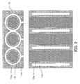
- FIG. 2 shows an example structure of the battery container 12.
- the battery container 12 as a whole is a rectangular parallelepiped, through which a plurality of housing holes are provided at regular intervals.
- a battery cell 10a is inserted into one of the housing holes.
- the battery cell 10a is contained in a cylindrical package, and the periphery of this package is in contact with the housing hole.
- the contact it is preferable that the contact be made over as large an area as possible, and it is also suitable that a material having an excellent thermal conductivity, such as an epoxy resin, is filled in a space between an inner surface of the housing hole and the peripheral surface of the battery cell 10a.
- a toroidal space 14a is provided around the battery cell 10a, and this space constitutes the condenser 14. Specifically, vapor (in this example, water vapor) of a heating medium coming from the evaporator 16 is introduced into the space 14a, and heat of condensation generated at that time causes the battery cell 10a to be heated via the battery container 12, and causes the battery 10 to be heated.
- the battery container 12 is preferably formed of a thermally conductive metal, but can also be formed of plastic. Further, as shown in FIG. 2 , portions other than the housing holes and the spaces 14a are preferably solid, but may be formed to be hollow using a flat material. It should be noted that the spaces 14a are each a passage for a heating medium.
- a heating medium in this example, water or water vapor
- Water vapor vaporized in the evaporator 16 is cooled by the battery 10 in the condenser 14, and turns into a liquid (water), and then, water which has been turned into a liquid state is circulated to the evaporator 16.
- the evaporator 16 vaporizes water by means of heat coming from the heat source 18.
- a structure of a typical heat exchanger can be used, and the evaporator causes heat coming from a heat source to act on a heating medium flowing in a heating medium channel to heat and vaporize the heating medium.
- An electric air conditioner includes a heat pump having a condenser and an evaporator, pressurizes a heating medium by means of a compressor, and supplies it to the condenser, in which, by closing a discharge side of the condenser to achieve a high pressure therein, the condenser can be heated to a high temperature. Then, the heat of the condenser can be transferred to the evaporator 16.
- the heat source 18 is not limited to this example, but a vehicle-mounted heat generation source such as an engine or a radiator can be used, or a dedicated heater may be provided.
- the controller controls heat coming from the heat source 18 in accordance with the temperature and the pressure of the heating medium in the inside of the evaporator 16 to control the temperature and the pressure of the heating medium in the evaporator 16. For example, while the inside of the evaporator 16 is kept in a substantially vacuum state at a pressure at which, when the heating medium is vaporized, the boiling point of the heating medium is 55°C, heating is controlled such that the temperature of vapor of the heating medium is 55°C. As a result, the heating medium vaporizes in the evaporator 16, and condenses in the condenser 14 while the temperature is kept at 55°C, and the heating medium of 55°C returns to the evaporator 16 to control the amount of heat coming from the heat source 18.
- the battery 10 can be heated by condensing vapor in the condenser 14.
- the temperature of vapor to be supplied to the condenser 14 is set to be rather somewhat higher than the boiling point, and the temperature of the heating medium to be returned is set to be rather lower than the boiling point so that the cycle is stabilized.
- a hybrid electric vehicle has a secondary battery mounted therein, in which the secondary battery is used to drive a motor generator, and power generated by the motor generator or regenerative power are used to charge the secondary battery.
- a secondary battery in an electric vehicle is charged by externally supplied power rather than power generated by a motor generator
- electric vehicles are similar to hybrid electric vehicles in that a secondary battery mounted in a vehicle is charged and discharged.
- a lithium ion secondary battery is used as the battery 10 mounted in such a vehicle.
- the lithium ion secondary battery has a high electrolyte viscosity at low temperatures, and has a high internal resistance at low temperatures.
- a lead acid battery (2 kW) having good output characteristics is used as a power source for the electric air conditioner.
- Heat is generated by driving an inverter air conditioner in a heat-up mode.
- the heat in theory, heat of about 7°C, 14 kW, can be generated.
- results of simulation of heating are shown in FIG. 3 .
- the results show that vacuum vapor heating according to the present embodiment allows the quickest start-up, and also allows fast temperature increase. This is because the heat capacity for heating the heating medium is incomparably small and the coefficient of heat transfer is high in vacuum vapor heating, as compared with cases where water or oil is circulated. This simulation assumes that water will not freeze. Further, air does not allow sufficient temperature increase as it has a low coefficient of heat transfer.
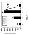
- FIG. 4 shows sensible heat losses for cases where heating is performed using the respective media from -30 °C to 7°C.
- a medium having a large heat capacity such as oil or water exhibits a high sensible heat loss, and causes a delay in temperature increase.
- the sensible heat loss of water vapor is about 1/9 that of water, and is approximately the same as that of air. It should be noted that this example also assumes that water is in the form of liquid.
- FIG. 5 shows coefficients of heat transfer for cases where heating is performed using the respective media from -30 °C to 7°C. As shown, water vapor has an exceptionally high coefficient of heat transfer, which is about 15 times that of water and 300 times that of air.
- the temperature of vapor in the condenser (evaporation and condensation temperature) to 7°C, under extremely cold temperature of as low as -30 °C, it is possible to increase the temperature up to 7°C in approximately one minute.
- liquid formed in the condenser 14 it is necessary to return liquid formed in the condenser 14 to the evaporator 16.
- liquid is circulated smoothly after the circulation cycle of the heating medium starts operating, for example, during startup, it is necessary to forcedly return liquid to the evaporator 16.
- the condenser 14 be located at a higher position than the evaporator 16 so that, when the operation ends, all liquid is returned to the evaporator 16. It should be noted that liquid may be returned by other means such as a pump.
- water is used as the heating medium
- the present invention is not limited to this embodiment. Any other substance which allows efficient use of evaporation latent heat may be used.
- a substance having a large evaporation latent heat such as ammonia, methanol, or ethanol is preferable, and a high coefficient of heat transfer can be provided.
- ammonia or carbon dioxide is used, as it has a high vapor density, loss does not tend to occur in a pipe or elsewhere; this structure is particularly preferable when the pipe is long.
- FIG. 6 shows a system in which a space in the battery container 12 is not used only as a condenser but also as a condenser/evaporator 50, and the evaporator 16 is used as a evaporator/condenser 54. It should be noted that it is a typical method to cause an evaporator and a condenser in a heat pump to respectively function in the opposite manner, and the present embodiment also employs this method.
- the condenser/evaporator 50 has a structure similar to that of the above-described condenser 14, and is formed as an inner space through which a heating medium circulates within the battery container 12 which houses the battery 10. When vapor is introduced into this space and is condensed into liquid, the condenser/evaporator 50 functions as a condenser, and, when a liquid heating medium is introduced and vaporized, the condenser/evaporator 50 functions as an evaporator.
- the evaporator/condenser 54 is connected to the condenser/evaporator 50 via a valve 52.
- the evaporator/condenser 54 has a structure similar to that of the above-described evaporator 16. When a liquid heating medium is supplied, the evaporator/condenser 54 heats and vaporizes it, and functions as an evaporator, and, when vapor is introduced, the evaporator/condenser 54 performs heat dissipation and condensation, and functions as a condenser.
- the condenser/evaporator 50 is connected to the evaporator/condenser 54 via a three-way valve 56.
- the temperature of the battery 10 can be increased by vaporizing a heating medium in the evaporator/condenser 54, introducing the resultant vapor into the condenser/evaporator 50, condensing the vapor there, and circulating it in the form of liquid to the evaporator/condenser 54.
- an adsorber 58 is connected via the three-way valve 56. This adsorber adsorbs vapor formed in the condenser/evaporator 50 while the battery is cooled, and later, desorbs the adsorbed vapor, and, for example, the inside of it is filled with a vapor adsorbent such as silica gel.
- means for heating or cooling the evaporator/condenser 54 and the adsorber 58 is provided.
- An exhaust heat recovery unit 60 provided before the engine exhaust gas muffler recovers heat from exhaust gas into a heat medium such as water, which is used in, for example, a vehicle cabin heater; in this example, this water is supplied to a heat storage unit 62 to store heat.
- a heat storage unit 62 anything capable of storing heat may be used.
- a chemical heat storage unit is used.
- calcium is used, and heat is chemically stored by changing calcium hydroxide Ca(OH) 2 into CaO by means of heat.
- water when necessary, water is supplied, and heat is dissipated by changing CaO into Ca(OH) 2 so that the heat medium (water) is heated to produce a high-temperature heat medium (hot water).
- the hot water produced in the heat storage unit 62 is supplied to the evaporator/condenser 54 or the adsorber 58 via a four-way valve 64. Further, the medium coming from the evaporator/condenser 54 or the adsorber 58 is circulated to the exhaust heat recovery unit 60 via a four-way valve 66.
- a low-temperature coolant (cooling water) coming from an external cooler 68 is stored in a heat accumulator 70.
- the external cooler 68 is composed of, for example, a radiator which is used for cooling, for example, an engine.
- the heat accumulator 70 anything capable of storing heat may be used. In this example, cooling water is simply stored.
- the cooling water coming from the heat accumulator 70 is supplied to the adsorber 58 or the evaporator/condenser 54 via the four-way valve 64. Further, the medium coming from the adsorber 58 or the evaporator/condenser 54 is circulated to the external cooler 68 via the four-way valve 66 and a pump 72.
- a hot water line for which the exhaust heat recovery unit 60 serves as a heat source and a cooling water line for which the external cooler 68 serves as a cooling source are provided separately from a line for the heating medium (water), and the evaporator/condenser 54 and the adsorber 58 can be heated or cooled.
- the heat accumulator 70 is connected to the heat storage unit 62 via a valve 74 so that heat from the heat accumulator 70 can be dissipated to the heat storage unit 62.
- exhaust heat recovery unit 60 and the heat storage unit 62 are used as examples of a heat source for hot water, heat may also be generated from a combustor or electrical energy. Also, the adsorber 58 may be replaced with a chemical reaction.
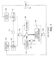
- a heat-up mode in which the temperature of the battery is increased in the above-described system will be described below with reference to FIG. 7 .
- the evaporator/condenser 54 functions as an evaporator. Therefore, the four-way valve 64 supplies hot water coming from the heat storage unit 62 to the evaporator/condenser 54. The hot water coming from the evaporator/condenser 54 is circulated to the exhaust heat recovery unit 60 via the four-way valve 66.
- heat recovered by the exhaust heat recovery unit 60 is supplied to the evaporator/condenser 54, and the heating medium is vaporized here.
- the vaporized heating medium is supplied to the condenser/evaporator 50 via the three-way valve 56, and turns into water here. Further, the resultant water is circulated to the evaporator/condenser 54.
- the valve 52 is left open.
- heat supplied to the evaporator/condenser 54 is supplied to the battery via the battery container 12 in the form of heat of condensation, and the battery 10 is heated. Further, by regulating the temperature and the pressure of the heating medium in the evaporator/condenser 54, it is possible to set the temperature of the battery to a predetermined temperature in a short time.
- FIG. 8 illustrates a cooling mode.
- the evaporator/condenser 54 is used as a condenser, and a liquid heating medium (water) produced therein is supplied to the condenser/evaporator 50.
- the valve 52 is left open.
- the condenser/evaporator 50 vaporizes water to produce water vapor, and the water vapor is introduced into the adsorber 58 via the three-way valve 56.
- the adsorber 58 has, for example, silica gel, and the silica gel adsorbs vapor. In this process, the surface of the battery container 12 is cooled to a temperature corresponding to the pressure on the adsorber 58 side.
- the adsorber 58 generates heat corresponding to the amount of vapor adsorbed, and this heat is discharged into cooling water. Further, when the temperature of the cooling water is high and the battery 10 cannot be cooled sufficiently, it is preferable to open the valve 74 located between the heat storage unit 62 and the heat accumulator 70 to cause the heat storage unit 62 to absorb heat to turn the heat accumulator 70 into a heat dissipation mode so that the temperature of the cooling water is lowered and the pressure in the adsorber 58 is reduced.
- the cooling water cooled in the external cooler 68 is supplied to the adsorber 58 via the four-way valve 64 to cool the adsorber 58. Therefore, heat generated in the adsorber 58 is removed by the cooling water. Further, the cooling water may also be supplied to the evaporator/condenser 54 to cool the evaporator/condenser 54.
- vapor generated in the condenser/evaporator 50 is adsorbed by the adsorber 58, and is not circulated to the evaporator/condenser 54. Therefore, the temperature of vapor in the condenser/evaporator 50 can also be made lower than the temperature of water in the evaporator/condenser 54, and the battery can be cooled effectively.
- FIG. 9 illustrates an adsorber regeneration mode.
- the hot water coming from the heat storage unit 62 is supplied to the adsorber 58 via the three-way valve.
- the adsorber 58 is heated, and the adsorbed heating medium (water) is desorbed in the form of water vapor.
- the resultant water vapor is introduced into the evaporator/condenser 54 via the three-way valve.
- the valve 52 is left closed.
- the cooling water coming from the heat accumulator 70 is supplied to the evaporator/condenser 54 via the four-way valve 64, and the heating medium (water vapor) turns into a liquid (water) here. Because, as described above, in the adsorber regeneration mode, the heating medium is condensed by cooling the evaporator/condenser 54, it is unnecessary to cool the evaporator/condenser 54 in the cooling mode.
- the above-described cooling mode is performed at the time when it is necessary, and, after it is completed, the adsorber regeneration mode is performed. Further, by repeating the two modes as needed, the battery 10 is cooled as necessary.
- FIG. 10 shows an outline of cooling of the battery 10.
- the condenser/evaporator 50 is denoted as the evaporator 50
- the evaporator/condenser 54 is denoted as the condenser 54.
- Condensed water produced in the condenser 54 is supplied to the evaporator 50.
- the evaporator 50 is formed as a space into which the heating medium (water) is introduced, within the battery container 12 which houses the battery 10. Therefore, as the condensed water vaporizes in the evaporator 50, the battery 10 is cooled, and the water vapor produced as a result of vaporization is introduced into and adsorbed by the adsorber 58.
- the adsorber 58 After the water vapor is temporarily adsorbed by the adsorber 58, heat coming from the heat source (exhaust heat recovery unit) 60 is caused to act on the adsorber 58 so that the water vapor is desorbed from the adsorbent, and the water vapor is introduced into the condenser 54, and is condensed here.
- the temperature and the pressure of the adsorber 58 are supplied to the controller 28, and the controller 28 determines, based on the temperature of the battery 10, whether or not cooling is necessary, and, when cooling is necessary, calculates an amount of heat of cooling which is required for cooling the battery, based on the temperature of the battery. Then, the adsorber 58 is cooled to lower the pressure therein.
- the adsorber 58 is connected with the evaporator 50, and heat coming from the heat source (exhaust heat recovery unit) 60 is supplied to the adsorber. As a result, water vapor is desorbed from the adsorber 58, and the adsorber 58 is regenerated. Further, the water vapor coming from the adsorber 58 is introduced into the condenser 54, and is cooled to turn into water.
- the heat source exhaust heat recovery unit
- the structure according to the above-described embodiment includes the evaporator 50 serving as a heat exchanger for cooling the battery, and includes an adsorbing type freezer having the adsorber 58 which absorbs or adsorbs a heating medium coming from the evaporator 50.
- the evaporator 50 serving as a heat exchanger for cooling the battery
- an adsorbing type freezer having the adsorber 58 which absorbs or adsorbs a heating medium coming from the evaporator 50.
Abstract
Description
- The present invention relates to a battery heating device for heating a battery by means of heat of condensation of a heating medium.
- A mobile body such as a vehicle having a battery mounted therein uses energy supplied from the battery for driving the vehicle or for other purposes. The energy output efficiency or other factors of the battery are affected by temperature. In particular, at low temperatures, because the viscosity of a liquid electrolyte within the battery or reaction resistance is increased, sufficient power cannot be obtained, and, on the other hand, if the temperature is too high, battery constituent materials may be adversely affected. Therefore, management of the temperature of the battery is important.
-
Patent Document 1 describes a structure provided with a heat exchanger for circulating a heating medium to be circulated in a water-cooled engine, in which this heat exchanger is used to warm up a battery. Further, Patent Document 2 discloses that a battery is heated by heat (Joule heat) generated in electric wire for driving a motor using power supplied from a generator. -
- Patent Document 1:
JP 2008-290636 A - Patent Document 2:
JP 2008-230508 A - Patent Document 3:
JP 2008-305575 A - Because the performance of a battery at low temperatures is significantly low, there is a demand that the battery be heated as quickly as possible. When heat generated in wire is used, the energy will be correspondingly wasted. Further, in a conventional heat exchanger, it has been difficult to add heat quickly.
- Further, as a too high temperature may adversely affect battery constituent materials, Patent Document 3 discloses a structure wherein water vapor obtained by a condensation evaporator is fed to an adsorber during cold startup, thermal energy is provided to the adsorber by heat of condensation, and a battery pack is heated using heat exchanging fluid by means of heat coming from the adsorber.
- According to one aspect of the present invention, there is provided a battery temperature adjustment device comprising a battery container for housing a battery; a condenser for condensing a heating medium to heat the battery container by heat transfer, the condenser being formed such that the heating medium is in direct or indirect contact with a surface of the battery container; and an evaporator for heating and vaporizing the heating medium condensed by the condenser, wherein the heating medium vaporized by the evaporator which is in vapor is circulated to the condenser.
- Further, according to another aspect of the present invention, there is provided a battery temperature adjustment device comprising a battery container for housing a battery; a heat exchanger for vaporizing a heating medium to cool the battery via the battery container by heat transfer, the heat exchanger being connected to the battery container; and a condenser for cooling and condensing the heating medium vaporized by the heat exchanger, wherein the heating medium condensed by the condenser which is in liquid is vaporized by the heat exchanger.
- Further, according to still another aspect of the present invention, there is provided a battery temperature adjustment device comprising a battery container for housing a battery; a heat exchanger for vaporizing or condensing a heating medium to cool or heat the battery via the battery container by heat transfer, the heat exchanger being connected to the battery container; an adsorber for adsorbing the heating medium vaporized by the heat exchanger; and a condenser/evaporator for either cooling and condensing vapor of the heating medium desorbed from the adsorber, or vaporizing the heating medium condensed by the heat exchanger which is in liquid.
- By employing the present invention, it is possible to effectively heat a battery using heat of condensation of a heating medium. Further, it is also possible to effectively cool a battery using heat of vaporization of a heating medium.
-
- [
FIG. 1 ]
FIG. 1 shows a schematic structure of a battery temperature adjustment device according to an embodiment of the present invention. - [
FIG. 2 ]
FIG. 2 shows an example structure of a battery container. - [
FIG. 3 ]
FIG. 3 shows heating characteristics produced by various types of heating media. - [
FIG. 4 ]
FIG. 4 shows sensible heat losses of various types of heating media. - [
FIG. 5 ]
FIG. 5 shows coefficients of heat transfer of various types of heating media. - [
FIG. 6 ]
FIG. 6 shows a structure of a cooling and heating system. - [
FIG. 7 ]
FIG. 7 is a diagram for explaining a heat-up mode. - [
FIG. 8 ]
FIG. 8 is a diagram for explaining a cooling mode. - [
FIG. 9 ]
FIG. 9 is a diagram for explaining an adsorber regeneration mode. - [
FIG. 10 ]
FIG. 10 shows a structure for cooling a battery. -
FIG. 1 shows a schematic structure of a battery temperature adjustment device according to an embodiment of the present invention. Abattery 10 is housed in abattery container 12. A heating medium passage is formed in thebattery container 12 near where it houses thebattery 10, and this portion constitutes acondenser 14. Anevaporator 16 is connected to thecondenser 14, and a heating medium circulates between them. Further, aheat source 18 is thermally connected to theevaporator 16, and heat coming from theheat source 18 is used to vaporize the heating medium in theevaporator 16. - The
heat source 18 is provided with athermometer 20, theevaporator 16 is provided with athermometer 22 and apressure gage 24, and their detection results are supplied to acontroller 28. Thecontroller 28 controls theheat source 18 to regulate the temperature and the pressure of theheat source 18 and theevaporator 16. Further, in this example, avalve 30 is provided in a channel through which a heating medium is returned from thecondenser 14 to theevaporator 16. - The
battery 10 is a secondary battery, and, for example, a lithium ion battery is used. In lithium ion batteries, in particular, the liquid electrolyte has a high viscosity, the internal resistance is high at low temperatures, and the power input and output characteristics are significantly deteriorated at low temperatures. As such, when the temperature is low, it is necessary to add heat rapidly to obtain sufficient capability. It should be noted that thebattery 10 is composed of a plurality of battery cells, and is, for example, a battery pack in which a plurality of battery cells each having a voltage of about several volts are serially connected to each other to obtain power of several hundred volts. - The
battery container 12 has, for example, a number of housing holes corresponding to the number of the battery cells, each housing hole housing one battery cell. It should be noted that the battery cells are electrically connected to each other, and, when viewed as a battery pack, have an external output terminal to which a cable is connected, and are collectively insulated. -
FIG. 2 shows an example structure of thebattery container 12. Thebattery container 12 as a whole is a rectangular parallelepiped, through which a plurality of housing holes are provided at regular intervals. Abattery cell 10a is inserted into one of the housing holes. In this example, thebattery cell 10a is contained in a cylindrical package, and the periphery of this package is in contact with the housing hole. To improve heat conduction, it is preferable that the contact be made over as large an area as possible, and it is also suitable that a material having an excellent thermal conductivity, such as an epoxy resin, is filled in a space between an inner surface of the housing hole and the peripheral surface of thebattery cell 10a. - A
toroidal space 14a is provided around thebattery cell 10a, and this space constitutes thecondenser 14. Specifically, vapor (in this example, water vapor) of a heating medium coming from theevaporator 16 is introduced into thespace 14a, and heat of condensation generated at that time causes thebattery cell 10a to be heated via thebattery container 12, and causes thebattery 10 to be heated. Thebattery container 12 is preferably formed of a thermally conductive metal, but can also be formed of plastic. Further, as shown inFIG. 2 , portions other than the housing holes and thespaces 14a are preferably solid, but may be formed to be hollow using a flat material. It should be noted that thespaces 14a are each a passage for a heating medium. - Specifically, the inside of the
condenser 14 and theevaporator 16, together with pipes connecting therebetween, forms an enclosed space in which a heating medium (in this example, water or water vapor) is circulated. Water vapor vaporized in theevaporator 16 is cooled by thebattery 10 in thecondenser 14, and turns into a liquid (water), and then, water which has been turned into a liquid state is circulated to theevaporator 16. - The
evaporator 16 vaporizes water by means of heat coming from theheat source 18. As an evaporator, a structure of a typical heat exchanger can be used, and the evaporator causes heat coming from a heat source to act on a heating medium flowing in a heating medium channel to heat and vaporize the heating medium. - As the
heat source 18, various types of structures can be used, and, for example, an electric air conditioner mounted in a vehicle may be used. An electric air conditioner includes a heat pump having a condenser and an evaporator, pressurizes a heating medium by means of a compressor, and supplies it to the condenser, in which, by closing a discharge side of the condenser to achieve a high pressure therein, the condenser can be heated to a high temperature. Then, the heat of the condenser can be transferred to theevaporator 16. Theheat source 18 is not limited to this example, but a vehicle-mounted heat generation source such as an engine or a radiator can be used, or a dedicated heater may be provided. - The controller controls heat coming from the
heat source 18 in accordance with the temperature and the pressure of the heating medium in the inside of theevaporator 16 to control the temperature and the pressure of the heating medium in theevaporator 16. For example, while the inside of theevaporator 16 is kept in a substantially vacuum state at a pressure at which, when the heating medium is vaporized, the boiling point of the heating medium is 55°C, heating is controlled such that the temperature of vapor of the heating medium is 55°C. As a result, the heating medium vaporizes in theevaporator 16, and condenses in thecondenser 14 while the temperature is kept at 55°C, and the heating medium of 55°C returns to theevaporator 16 to control the amount of heat coming from theheat source 18. As a result, thebattery 10 can be heated by condensing vapor in thecondenser 14. Practically, it is preferable that the temperature of vapor to be supplied to thecondenser 14 is set to be rather somewhat higher than the boiling point, and the temperature of the heating medium to be returned is set to be rather lower than the boiling point so that the cycle is stabilized. - A hybrid electric vehicle has a secondary battery mounted therein, in which the secondary battery is used to drive a motor generator, and power generated by the motor generator or regenerative power are used to charge the secondary battery. Further, although a secondary battery in an electric vehicle is charged by externally supplied power rather than power generated by a motor generator, electric vehicles are similar to hybrid electric vehicles in that a secondary battery mounted in a vehicle is charged and discharged. As the
battery 10 mounted in such a vehicle, for example, a lithium ion secondary battery is used. The lithium ion secondary battery has a high electrolyte viscosity at low temperatures, and has a high internal resistance at low temperatures. In the present embodiment, by adding heat using vapor, it is possible to quickly lower the internal resistance to drive the motor at low temperatures making full use of the capacity of the battery. Further, when the battery has a low temperature and a high internal resistance, an attempt to store all regenerative energy in thebattery 10 will increase overvoltage within thebattery 10 to cause precipitation of metal lithium, which tends to result in deterioration of the capabilities of the battery. Therefore, it is necessary to increase the temperature of thebattery 10 quickly. - On the other hand, it is reported that, when the lithium ion secondary battery gets hot, it will deteriorate because a side reaction different from the battery reaction occurs within the battery. Therefore, when the battery is heated by increasing the temperature of a heat exchanger which is provided for heating the battery, monitoring or other means for preventing the temperature of the battery from reaching or exceeding a predetermined level is required. In the present embodiment, because heating is performed by condensing vapor in the
condenser 14 while the pressure of the vapor is being maintained at a predetermined value, the temperature of thecondenser 14 is maintained at the condensation temperature of the heating medium, and can be prevented from exceeding that level. Therefore, it is possible to reliably prevent thebattery 10 from reaching or exceeding a predetermined temperature. - An example in which an electric air conditioner as described above is used as the
heat source 18 will be described below. A lead acid battery (2 kW) having good output characteristics is used as a power source for the electric air conditioner. Heat is generated by driving an inverter air conditioner in a heat-up mode. As a result, as the heat, in theory, heat of about 7°C, 14 kW, can be generated. - For cases where heating is performed by convection heat transfer by means of vapor, water, oil, or air using the
heat source 18 as described above, results of simulation of heating (temperature increase results) are shown inFIG. 3 . In this simulation, it is also assumed that there are delays in the air conditioner. As such, a delay occurs even when any heating medium is used. However, the results show that vacuum vapor heating according to the present embodiment allows the quickest start-up, and also allows fast temperature increase. This is because the heat capacity for heating the heating medium is incomparably small and the coefficient of heat transfer is high in vacuum vapor heating, as compared with cases where water or oil is circulated. This simulation assumes that water will not freeze. Further, air does not allow sufficient temperature increase as it has a low coefficient of heat transfer. -
FIG. 4 shows sensible heat losses for cases where heating is performed using the respective media from -30 °C to 7°C. As shown, it should be understood that a medium having a large heat capacity such as oil or water exhibits a high sensible heat loss, and causes a delay in temperature increase. The sensible heat loss of water vapor is about 1/9 that of water, and is approximately the same as that of air. It should be noted that this example also assumes that water is in the form of liquid. -
FIG. 5 shows coefficients of heat transfer for cases where heating is performed using the respective media from -30 °C to 7°C. As shown, water vapor has an exceptionally high coefficient of heat transfer, which is about 15 times that of water and 300 times that of air. - It can be understood from these results that, when water vapor is used as the medium, a small sensible heat loss and a high heat transfer capability can be expected.
- In the present embodiment, for example, by setting the temperature of vapor in the condenser (evaporation and condensation temperature) to 7°C, under extremely cold temperature of as low as -30 °C, it is possible to increase the temperature up to 7°C in approximately one minute.
- In this process, it is necessary to return liquid formed in the
condenser 14 to theevaporator 16. Although liquid is circulated smoothly after the circulation cycle of the heating medium starts operating, for example, during startup, it is necessary to forcedly return liquid to theevaporator 16. For this purpose, it is preferable that thecondenser 14 be located at a higher position than the evaporator 16 so that, when the operation ends, all liquid is returned to theevaporator 16. It should be noted that liquid may be returned by other means such as a pump. - Further, although water is used as the heating medium, the present invention is not limited to this embodiment. Any other substance which allows efficient use of evaporation latent heat may be used. For example, a substance having a large evaporation latent heat such as ammonia, methanol, or ethanol is preferable, and a high coefficient of heat transfer can be provided. Further, when ammonia or carbon dioxide is used, as it has a high vapor density, loss does not tend to occur in a pipe or elsewhere; this structure is particularly preferable when the pipe is long.
-
FIG. 6 shows a system in which a space in thebattery container 12 is not used only as a condenser but also as a condenser/evaporator 50, and theevaporator 16 is used as a evaporator/condenser 54. It should be noted that it is a typical method to cause an evaporator and a condenser in a heat pump to respectively function in the opposite manner, and the present embodiment also employs this method. - The condenser/
evaporator 50 has a structure similar to that of the above-describedcondenser 14, and is formed as an inner space through which a heating medium circulates within thebattery container 12 which houses thebattery 10. When vapor is introduced into this space and is condensed into liquid, the condenser/evaporator 50 functions as a condenser, and, when a liquid heating medium is introduced and vaporized, the condenser/evaporator 50 functions as an evaporator. - The evaporator/
condenser 54 is connected to the condenser/evaporator 50 via avalve 52. The evaporator/condenser 54 has a structure similar to that of the above-describedevaporator 16. When a liquid heating medium is supplied, the evaporator/condenser 54 heats and vaporizes it, and functions as an evaporator, and, when vapor is introduced, the evaporator/condenser 54 performs heat dissipation and condensation, and functions as a condenser. The condenser/evaporator 50 is connected to the evaporator/condenser 54 via a three-way valve 56. Therefore, the temperature of thebattery 10 can be increased by vaporizing a heating medium in the evaporator/condenser 54, introducing the resultant vapor into the condenser/evaporator 50, condensing the vapor there, and circulating it in the form of liquid to the evaporator/condenser 54. - Further, in the present embodiment, an
adsorber 58 is connected via the three-way valve 56. This adsorber adsorbs vapor formed in the condenser/evaporator 50 while the battery is cooled, and later, desorbs the adsorbed vapor, and, for example, the inside of it is filled with a vapor adsorbent such as silica gel. - Further, in the present embodiment, means for heating or cooling the evaporator/
condenser 54 and theadsorber 58 is provided. An exhaustheat recovery unit 60 provided before the engine exhaust gas muffler recovers heat from exhaust gas into a heat medium such as water, which is used in, for example, a vehicle cabin heater; in this example, this water is supplied to aheat storage unit 62 to store heat. For theheat storage unit 62, anything capable of storing heat may be used. In this example, a chemical heat storage unit is used. For example, calcium is used, and heat is chemically stored by changing calcium hydroxide Ca(OH)2 into CaO by means of heat. Further, when necessary, water is supplied, and heat is dissipated by changing CaO into Ca(OH)2 so that the heat medium (water) is heated to produce a high-temperature heat medium (hot water). The hot water produced in theheat storage unit 62 is supplied to the evaporator/condenser 54 or theadsorber 58 via a four-way valve 64. Further, the medium coming from the evaporator/condenser 54 or theadsorber 58 is circulated to the exhaustheat recovery unit 60 via a four-way valve 66. - Further, a low-temperature coolant (cooling water) coming from an
external cooler 68 is stored in aheat accumulator 70. Theexternal cooler 68 is composed of, for example, a radiator which is used for cooling, for example, an engine. For theheat accumulator 70, anything capable of storing heat may be used. In this example, cooling water is simply stored. The cooling water coming from theheat accumulator 70 is supplied to theadsorber 58 or the evaporator/condenser 54 via the four-way valve 64. Further, the medium coming from theadsorber 58 or the evaporator/condenser 54 is circulated to theexternal cooler 68 via the four-way valve 66 and apump 72. - As described above, in the present embodiment, a hot water line for which the exhaust
heat recovery unit 60 serves as a heat source and a cooling water line for which theexternal cooler 68 serves as a cooling source are provided separately from a line for the heating medium (water), and the evaporator/condenser 54 and theadsorber 58 can be heated or cooled. - Further, the
heat accumulator 70 is connected to theheat storage unit 62 via avalve 74 so that heat from theheat accumulator 70 can be dissipated to theheat storage unit 62. - It should be noted that, although the exhaust
heat recovery unit 60 and theheat storage unit 62 are used as examples of a heat source for hot water, heat may also be generated from a combustor or electrical energy. Also, theadsorber 58 may be replaced with a chemical reaction. - A heat-up mode in which the temperature of the battery is increased in the above-described system will be described below with reference to
FIG. 7 . In this case, the evaporator/condenser 54 functions as an evaporator. Therefore, the four-way valve 64 supplies hot water coming from theheat storage unit 62 to the evaporator/condenser 54. The hot water coming from the evaporator/condenser 54 is circulated to the exhaustheat recovery unit 60 via the four-way valve 66. - Therefore, heat recovered by the exhaust
heat recovery unit 60 is supplied to the evaporator/condenser 54, and the heating medium is vaporized here. The vaporized heating medium is supplied to the condenser/evaporator 50 via the three-way valve 56, and turns into water here. Further, the resultant water is circulated to the evaporator/condenser 54. Thevalve 52 is left open. As a result, heat supplied to the evaporator/condenser 54 is supplied to the battery via thebattery container 12 in the form of heat of condensation, and thebattery 10 is heated. Further, by regulating the temperature and the pressure of the heating medium in the evaporator/condenser 54, it is possible to set the temperature of the battery to a predetermined temperature in a short time. -
FIG. 8 illustrates a cooling mode. In the cooling mode, the evaporator/condenser 54 is used as a condenser, and a liquid heating medium (water) produced therein is supplied to the condenser/evaporator 50. Thevalve 52 is left open. The condenser/evaporator 50 vaporizes water to produce water vapor, and the water vapor is introduced into theadsorber 58 via the three-way valve 56. Theadsorber 58 has, for example, silica gel, and the silica gel adsorbs vapor. In this process, the surface of thebattery container 12 is cooled to a temperature corresponding to the pressure on theadsorber 58 side. Further, theadsorber 58 generates heat corresponding to the amount of vapor adsorbed, and this heat is discharged into cooling water. Further, when the temperature of the cooling water is high and thebattery 10 cannot be cooled sufficiently, it is preferable to open thevalve 74 located between theheat storage unit 62 and theheat accumulator 70 to cause theheat storage unit 62 to absorb heat to turn theheat accumulator 70 into a heat dissipation mode so that the temperature of the cooling water is lowered and the pressure in theadsorber 58 is reduced. - Further, the cooling water cooled in the
external cooler 68 is supplied to theadsorber 58 via the four-way valve 64 to cool theadsorber 58. Therefore, heat generated in theadsorber 58 is removed by the cooling water. Further, the cooling water may also be supplied to the evaporator/condenser 54 to cool the evaporator/condenser 54. - In this process, in the present embodiment, vapor generated in the condenser/
evaporator 50 is adsorbed by theadsorber 58, and is not circulated to the evaporator/condenser 54. Therefore, the temperature of vapor in the condenser/evaporator 50 can also be made lower than the temperature of water in the evaporator/condenser 54, and the battery can be cooled effectively. -
FIG. 9 illustrates an adsorber regeneration mode. The hot water coming from theheat storage unit 62 is supplied to theadsorber 58 via the three-way valve. As a result, theadsorber 58 is heated, and the adsorbed heating medium (water) is desorbed in the form of water vapor. The resultant water vapor is introduced into the evaporator/condenser 54 via the three-way valve. In this process, thevalve 52 is left closed. The cooling water coming from theheat accumulator 70 is supplied to the evaporator/condenser 54 via the four-way valve 64, and the heating medium (water vapor) turns into a liquid (water) here. Because, as described above, in the adsorber regeneration mode, the heating medium is condensed by cooling the evaporator/condenser 54, it is unnecessary to cool the evaporator/condenser 54 in the cooling mode. - When the
battery 10 is to be cooled, the above-described cooling mode is performed at the time when it is necessary, and, after it is completed, the adsorber regeneration mode is performed. Further, by repeating the two modes as needed, thebattery 10 is cooled as necessary. -
FIG. 10 shows an outline of cooling of thebattery 10. InFIG. 10 , as it illustrates cooling, the condenser/evaporator 50 is denoted as theevaporator 50, and the evaporator/condenser 54 is denoted as thecondenser 54. - Condensed water produced in the
condenser 54 is supplied to theevaporator 50. Theevaporator 50 is formed as a space into which the heating medium (water) is introduced, within thebattery container 12 which houses thebattery 10. Therefore, as the condensed water vaporizes in theevaporator 50, thebattery 10 is cooled, and the water vapor produced as a result of vaporization is introduced into and adsorbed by theadsorber 58. After the water vapor is temporarily adsorbed by theadsorber 58, heat coming from the heat source (exhaust heat recovery unit) 60 is caused to act on theadsorber 58 so that the water vapor is desorbed from the adsorbent, and the water vapor is introduced into thecondenser 54, and is condensed here. The temperature and the pressure of theadsorber 58 are supplied to thecontroller 28, and thecontroller 28 determines, based on the temperature of thebattery 10, whether or not cooling is necessary, and, when cooling is necessary, calculates an amount of heat of cooling which is required for cooling the battery, based on the temperature of the battery. Then, theadsorber 58 is cooled to lower the pressure therein. After certain cooling is completed, theadsorber 58 is connected with theevaporator 50, and heat coming from the heat source (exhaust heat recovery unit) 60 is supplied to the adsorber. As a result, water vapor is desorbed from theadsorber 58, and theadsorber 58 is regenerated. Further, the water vapor coming from theadsorber 58 is introduced into thecondenser 54, and is cooled to turn into water. - As described above, desired cooling of the
battery 10 is achieved. If necessary, the above-described cooling and regeneration of the adsorber may be repeated. - As described above, the structure according to the above-described embodiment includes the
evaporator 50 serving as a heat exchanger for cooling the battery, and includes an adsorbing type freezer having theadsorber 58 which absorbs or adsorbs a heating medium coming from theevaporator 50. As a result, it is possible to cool the evaporator 50 to a temperature corresponding to the pressure in theadsorber 58 to set it to a temperature lower than the temperature in thecondenser 54. -
- 10
- BATTERY
- 12
- BATTERY CONTAINER
- 14
- CONDENSER
- 16
- EVAPORATOR
- 18
- HEAT SOURCE
- 20, 22
- THERMOMETER
- 24
- PRESSURE GAGE
- 28
- CONTROLLER
- 30
- VALVE
- 50
- CONDENSER/EVAPORATOR
- 54
- EVAPORATOR/CONDENSER
- 56
- THREE-WAY VALVE
- 58
- ADSORBER
- 60
- EXHAUST HEAT RECOVERY UNIT
- 62
- HEAT STORAGE UNIT
- 64, 66
- FOUR-WAY VALVE
- 68
- EXTERNAL COOLER
- 70
- HEAT ACCUMULATOR
- 72
- PUMP
- 74
- VALVE
Claims (10)
- A battery temperature adjustment device comprising:a battery container for housing a battery;a condenser for condensing a heating medium to heat the battery container by heat transfer, the condenser being formed such that the heating medium is in direct or indirect contact with a surface of the battery container; andan evaporator for heating and vaporizing the heating medium condensed by the condenser, whereinthe heating medium vaporized by the evaporator which is in vapor is circulated to the condenser.
- The battery temperature adjustment device according to claim 1, wherein
the condenser is formed such that the heating medium is in direct contact with the surface of the battery container. - The battery temperature adjustment device according to claim 1, wherein
the battery container has a battery housing hole, and the battery is housed in the battery housing hole. - The battery temperature adjustment device according to claim 3, wherein
the battery housing hole is provided through the battery container. - The battery temperature adjustment device according to claim 4, wherein
an inner surface of the battery housing hole and an outer surface of the battery are either in direct contact with each other, or in contact with each other via a thermally conductive material. - The battery temperature adjustment device according to claim 3, wherein
a passage for the heating medium is formed in the battery container such that it surrounds the battery housing hole, and the heating medium is condensed in the passage. - A battery temperature adjustment device comprising:a battery container for housing a battery;a heat exchanger for vaporizing a heating medium to cool the battery via the battery container by heat transfer, the heat exchanger being connected to the battery container; anda condenser for cooling and condensing the heating medium vaporized by the heat exchanger, whereinthe heating medium condensed by the condenser which is in liquid is vaporized by the heat exchanger.
- The battery temperature adjustment device according to claim 7, further comprising an adsorber, wherein
the heating medium vaporized by the heat exchanger is supplied to the adsorber and adsorbed by the adsorber, and later, heat is supplied to the adsorber and causes the adsorber to desorb vapor of the heating medium to regenerate the adsorber, and vapor coming from the adsorber is condensed by the condenser. - A battery temperature adjustment device comprising:a battery container for housing a battery;a heat exchanger for vaporizing or condensing a heating medium to cool or heat the battery via the battery container by heat transfer, the heat exchanger being connected to the battery container;an adsorber for adsorbing the heating medium vaporized by the heat exchanger; anda condenser/evaporator for either cooling and condensing vapor of the heating medium desorbed from the adsorber, or vaporizing the heating medium condensed by the heat exchanger which is in liquid.
- The battery temperature adjustment device according to any one of claims 1 to 9, wherein
the heating medium is water.
Applications Claiming Priority (2)
| Application Number | Priority Date | Filing Date | Title |
|---|---|---|---|
| JP2010111871A JP5437906B2 (en) | 2010-05-14 | 2010-05-14 | Battery heating device |
| PCT/JP2011/060974 WO2011142431A1 (en) | 2010-05-14 | 2011-05-12 | Battery temperature adjustment device |
Publications (3)
| Publication Number | Publication Date |
|---|---|
| EP2571096A1 true EP2571096A1 (en) | 2013-03-20 |
| EP2571096A4 EP2571096A4 (en) | 2016-05-11 |
| EP2571096B1 EP2571096B1 (en) | 2017-08-16 |
Family
ID=44914483
Family Applications (1)
| Application Number | Title | Priority Date | Filing Date |
|---|---|---|---|
| EP11780688.5A Active EP2571096B1 (en) | 2010-05-14 | 2011-05-12 | Battery temperature adjustment device |
Country Status (5)
| Country | Link |
|---|---|
| US (1) | US9660307B2 (en) |
| EP (1) | EP2571096B1 (en) |
| JP (1) | JP5437906B2 (en) |
| CN (1) | CN102939685B (en) |
| WO (1) | WO2011142431A1 (en) |
Cited By (1)
| Publication number | Priority date | Publication date | Assignee | Title |
|---|---|---|---|---|
| EP3483979A1 (en) * | 2017-11-09 | 2019-05-15 | MAN Truck & Bus AG | Technique for regulating the temperature of a traction energy storage unit |
Families Citing this family (14)
| Publication number | Priority date | Publication date | Assignee | Title |
|---|---|---|---|---|
| JP6145297B2 (en) * | 2013-04-15 | 2017-06-07 | 矢崎総業株式会社 | Warm-up device |
| JP6131130B2 (en) * | 2013-07-01 | 2017-05-17 | 日野自動車株式会社 | Battery temperature control device for hybrid vehicle |
| EP3025887B1 (en) * | 2013-07-26 | 2018-04-25 | Panasonic Intellectual Property Management Co., Ltd. | Vehicle air conditioner |
| JP5909466B2 (en) * | 2013-08-22 | 2016-04-26 | 公益財団法人三重県産業支援センター | refrigerator |
| JP2015216723A (en) * | 2014-05-08 | 2015-12-03 | 矢崎総業株式会社 | System for utilizing waste heat of non-contact power supply |
| US20160380247A1 (en) * | 2015-06-25 | 2016-12-29 | Iontensity, LLC | Battery Packs Having Single Stacks of Battery Cells |
| JP6222283B1 (en) * | 2016-05-31 | 2017-11-01 | マツダ株式会社 | Secondary battery temperature control device for vehicle |
| JP2017216099A (en) * | 2016-05-31 | 2017-12-07 | マツダ株式会社 | Secondary battery warming device of vehicle |
| WO2018163180A1 (en) * | 2017-03-09 | 2018-09-13 | Zuta-Core Ltd. | Systems and methods for thermal regulation |
| TWI651880B (en) * | 2017-06-16 | 2019-02-21 | 大青節能科技公司 | Electric vehicle with temperature adjustable battery |
| DE102017219792A1 (en) * | 2017-11-08 | 2019-05-09 | Robert Bosch Gmbh | Energy storage system and method for operating the energy storage system |
| WO2019105909A1 (en) * | 2017-11-28 | 2019-06-06 | Fahrenheit Gmbh | Method for controlling the temperature of a battery arrangement and temperature-controlled battery arrangement |
| US10752129B2 (en) * | 2018-10-26 | 2020-08-25 | Pratt & Whitney Canada Corp. | Battery heating in hybrid electric power plant |
| CN112436212A (en) * | 2020-12-04 | 2021-03-02 | 湖南电将军新能源有限公司 | Low-temperature discharging aluminum-rich lithium fast charging battery |
Family Cites Families (16)
| Publication number | Priority date | Publication date | Assignee | Title |
|---|---|---|---|---|
| JP2003287328A (en) * | 2002-03-27 | 2003-10-10 | Takenaka Komuten Co Ltd | Cooling system for electric appliance |
| CN2567527Y (en) * | 2002-08-02 | 2003-08-20 | 淮安市淮阴辉煌真空镀膜有限公司 | Solar cold tube of cold output from one end and heat output from another end |
| JP2004293872A (en) * | 2003-03-26 | 2004-10-21 | Tokyo Electric Power Co Inc:The | Heat pump and device using heat |
| DE102005017648B4 (en) * | 2005-04-15 | 2008-01-10 | Daimlerchrysler Ag | Liquid cooled battery and method of operating such |
| JP2008230508A (en) | 2007-03-22 | 2008-10-02 | Toyota Motor Corp | Power control device for hybrid vehicle |
| JP4958637B2 (en) | 2007-05-26 | 2012-06-20 | 三洋電機株式会社 | Hybrid car |
| JP5182546B2 (en) | 2007-06-05 | 2013-04-17 | 株式会社デンソー | Battery temperature control device |
| JP2009037934A (en) * | 2007-08-02 | 2009-02-19 | Sanyo Electric Co Ltd | Power supply device for vehicle |
| ATE515730T1 (en) * | 2007-10-03 | 2011-07-15 | Parker Hannifin Corp | FUEL CELL/BATTERY HEAT MANAGEMENT SYSTEM |
| JP2009154698A (en) * | 2007-12-26 | 2009-07-16 | Calsonic Kansei Corp | Battery temperature control device |
| JP2009259785A (en) * | 2008-03-24 | 2009-11-05 | Sanyo Electric Co Ltd | Battery device |
| WO2009119037A1 (en) | 2008-03-24 | 2009-10-01 | 三洋電機株式会社 | Battery device and battery unit |
| JP2009259454A (en) * | 2008-04-14 | 2009-11-05 | Toyota Motor Corp | Battery |
| JP2010050000A (en) * | 2008-08-22 | 2010-03-04 | Sanyo Electric Co Ltd | Power source device for vehicle |
| CN101533932A (en) * | 2008-08-29 | 2009-09-16 | 耿直 | Constant temperature method for storage battery |
| US20100070092A1 (en) * | 2008-09-16 | 2010-03-18 | Williams Furnace Company | System and method for controlling a room environment |
-
2010
- 2010-05-14 JP JP2010111871A patent/JP5437906B2/en active Active
-
2011
- 2011-05-12 US US13/696,402 patent/US9660307B2/en active Active
- 2011-05-12 WO PCT/JP2011/060974 patent/WO2011142431A1/en active Application Filing
- 2011-05-12 EP EP11780688.5A patent/EP2571096B1/en active Active
- 2011-05-12 CN CN201180024084.7A patent/CN102939685B/en active Active
Non-Patent Citations (1)
| Title |
|---|
| See references of WO2011142431A1 * |
Cited By (1)
| Publication number | Priority date | Publication date | Assignee | Title |
|---|---|---|---|---|
| EP3483979A1 (en) * | 2017-11-09 | 2019-05-15 | MAN Truck & Bus AG | Technique for regulating the temperature of a traction energy storage unit |
Also Published As
| Publication number | Publication date |
|---|---|
| WO2011142431A1 (en) | 2011-11-17 |
| US9660307B2 (en) | 2017-05-23 |
| EP2571096A4 (en) | 2016-05-11 |
| CN102939685A (en) | 2013-02-20 |
| CN102939685B (en) | 2015-07-01 |
| JP5437906B2 (en) | 2014-03-12 |
| US20130059191A1 (en) | 2013-03-07 |
| JP2011243309A (en) | 2011-12-01 |
| EP2571096B1 (en) | 2017-08-16 |
Similar Documents
| Publication | Publication Date | Title |
|---|---|---|
| EP2571096B1 (en) | Battery temperature adjustment device | |
| CN105452025B (en) | Temperature controller for battery | |
| CN104247142B (en) | Battery system and its cooling means | |
| US8899492B2 (en) | Method of controlling system temperature to extend battery pack life | |
| EP2781380B1 (en) | Device for cooling electrical apparatus | |
| US20130022888A1 (en) | Fuel cell cooling system with coupling out of heat | |
| KR20160120293A (en) | Passive Temperature Control Of Accumulators | |
| KR20120106887A (en) | Thermal management of an electrochemical cell by a combination of heat transfer fluid and phase change material | |
| CN108493514B (en) | Heat dissipation and heating device of battery pack and control method | |
| JP2011049139A (en) | Battery device | |
| JP2014103005A (en) | Battery pack and in-vehicle heating system | |
| PT2321869E (en) | Method and device providing the temperature regulation of a rechargeable electrical energy storage battery | |
| Lei et al. | Separate and integrated thermal management solutions for electric vehicles: A review | |
| JP2010129392A (en) | Battery system | |
| KR20100041727A (en) | The cooling and heating system for battery to control temperature | |
| US20210167440A1 (en) | Method and device for controlling the temperature of a battery assembly | |
| CN108777336A (en) | Lithium battery pack heat management system | |
| US11358493B2 (en) | Fuel cell vehicle thermal management system and method for managing fuel cell thermal loads | |
| Maiorino et al. | A review on thermal management of battery packs for electric vehicles | |
| JP5437889B2 (en) | Battery cooling device and battery temperature control device | |
| Li et al. | Research progress on efficient thermal management system for electric vehicle batteries based on two-phase transformation | |
| Khan et al. | A state-of-the-art review on heating and cooling of lithium-ion batteries for electric vehicles | |
| US20230191868A1 (en) | Thermal management system, thermal management method and electrical device | |
| Sökmen et al. | Review of batteries thermal problems and thermal management systems | |
| CN111430836A (en) | Self-adaptive temperature adjusting structural unit and application thereof |
Legal Events
| Date | Code | Title | Description |
|---|---|---|---|
| PUAI | Public reference made under article 153(3) epc to a published international application that has entered the european phase |
Free format text: ORIGINAL CODE: 0009012 |
|
| 17P | Request for examination filed |
Effective date: 20121130 |
|
| AK | Designated contracting states |
Kind code of ref document: A1 Designated state(s): AL AT BE BG CH CY CZ DE DK EE ES FI FR GB GR HR HU IE IS IT LI LT LU LV MC MK MT NL NO PL PT RO RS SE SI SK SM TR |
|
| DAX | Request for extension of the european patent (deleted) | ||
| RA4 | Supplementary search report drawn up and despatched (corrected) |
Effective date: 20160408 |
|
| RIC1 | Information provided on ipc code assigned before grant |
Ipc: H01M 10/6556 20140101ALI20160404BHEP Ipc: F25B 13/00 20060101ALI20160404BHEP Ipc: H01M 10/615 20140101AFI20160404BHEP Ipc: H01M 2/10 20060101ALI20160404BHEP Ipc: H01M 2/02 20060101ALI20160404BHEP Ipc: H01M 10/0525 20100101ALN20160404BHEP Ipc: H01M 10/613 20140101ALI20160404BHEP Ipc: H01M 10/6569 20140101ALI20160404BHEP |
|
| REG | Reference to a national code |
Ref country code: DE Ref legal event code: R079 Ref document number: 602011040664 Country of ref document: DE Free format text: PREVIOUS MAIN CLASS: H01M0010500000 Ipc: H01M0010615000 |
|
| RIC1 | Information provided on ipc code assigned before grant |
Ipc: F25B 13/00 20060101ALI20170116BHEP Ipc: H01M 2/10 20060101ALI20170116BHEP Ipc: H01M 10/615 20140101AFI20170116BHEP Ipc: H01M 10/613 20140101ALI20170116BHEP Ipc: H01M 10/0525 20100101ALN20170116BHEP Ipc: H01M 2/02 20060101ALI20170116BHEP Ipc: H01M 10/6569 20140101ALI20170116BHEP Ipc: H01M 10/6556 20140101ALI20170116BHEP |
|
| GRAP | Despatch of communication of intention to grant a patent |
Free format text: ORIGINAL CODE: EPIDOSNIGR1 |
|
| INTG | Intention to grant announced |
Effective date: 20170306 |
|
| GRAS | Grant fee paid |
Free format text: ORIGINAL CODE: EPIDOSNIGR3 |
|
| GRAA | (expected) grant |
Free format text: ORIGINAL CODE: 0009210 |
|
| AK | Designated contracting states |
Kind code of ref document: B1 Designated state(s): AL AT BE BG CH CY CZ DE DK EE ES FI FR GB GR HR HU IE IS IT LI LT LU LV MC MK MT NL NO PL PT RO RS SE SI SK SM TR |
|
| REG | Reference to a national code |
Ref country code: GB Ref legal event code: FG4D |
|
| REG | Reference to a national code |
Ref country code: CH Ref legal event code: EP |
|
| REG | Reference to a national code |
Ref country code: IE Ref legal event code: FG4D |
|
| REG | Reference to a national code |
Ref country code: AT Ref legal event code: REF Ref document number: 919912 Country of ref document: AT Kind code of ref document: T Effective date: 20170915 |
|
| REG | Reference to a national code |
Ref country code: DE Ref legal event code: R096 Ref document number: 602011040664 Country of ref document: DE |
|
| REG | Reference to a national code |
Ref country code: NL Ref legal event code: MP Effective date: 20170816 |
|
| REG | Reference to a national code |
Ref country code: LT Ref legal event code: MG4D |
|
| REG | Reference to a national code |
Ref country code: AT Ref legal event code: MK05 Ref document number: 919912 Country of ref document: AT Kind code of ref document: T Effective date: 20170816 |
|
| PG25 | Lapsed in a contracting state [announced via postgrant information from national office to epo] |
Ref country code: LT Free format text: LAPSE BECAUSE OF FAILURE TO SUBMIT A TRANSLATION OF THE DESCRIPTION OR TO PAY THE FEE WITHIN THE PRESCRIBED TIME-LIMIT Effective date: 20170816 Ref country code: SE Free format text: LAPSE BECAUSE OF FAILURE TO SUBMIT A TRANSLATION OF THE DESCRIPTION OR TO PAY THE FEE WITHIN THE PRESCRIBED TIME-LIMIT Effective date: 20170816 Ref country code: NO Free format text: LAPSE BECAUSE OF FAILURE TO SUBMIT A TRANSLATION OF THE DESCRIPTION OR TO PAY THE FEE WITHIN THE PRESCRIBED TIME-LIMIT Effective date: 20171116 Ref country code: FI Free format text: LAPSE BECAUSE OF FAILURE TO SUBMIT A TRANSLATION OF THE DESCRIPTION OR TO PAY THE FEE WITHIN THE PRESCRIBED TIME-LIMIT Effective date: 20170816 Ref country code: AT Free format text: LAPSE BECAUSE OF FAILURE TO SUBMIT A TRANSLATION OF THE DESCRIPTION OR TO PAY THE FEE WITHIN THE PRESCRIBED TIME-LIMIT Effective date: 20170816 Ref country code: NL Free format text: LAPSE BECAUSE OF FAILURE TO SUBMIT A TRANSLATION OF THE DESCRIPTION OR TO PAY THE FEE WITHIN THE PRESCRIBED TIME-LIMIT Effective date: 20170816 |
|
| REG | Reference to a national code |
Ref country code: DE Ref legal event code: R084 Ref document number: 602011040664 Country of ref document: DE |
|
| PG25 | Lapsed in a contracting state [announced via postgrant information from national office to epo] |
Ref country code: GR Free format text: LAPSE BECAUSE OF FAILURE TO SUBMIT A TRANSLATION OF THE DESCRIPTION OR TO PAY THE FEE WITHIN THE PRESCRIBED TIME-LIMIT Effective date: 20171117 Ref country code: LV Free format text: LAPSE BECAUSE OF FAILURE TO SUBMIT A TRANSLATION OF THE DESCRIPTION OR TO PAY THE FEE WITHIN THE PRESCRIBED TIME-LIMIT Effective date: 20170816 Ref country code: PL Free format text: LAPSE BECAUSE OF FAILURE TO SUBMIT A TRANSLATION OF THE DESCRIPTION OR TO PAY THE FEE WITHIN THE PRESCRIBED TIME-LIMIT Effective date: 20170816 Ref country code: IS Free format text: LAPSE BECAUSE OF FAILURE TO SUBMIT A TRANSLATION OF THE DESCRIPTION OR TO PAY THE FEE WITHIN THE PRESCRIBED TIME-LIMIT Effective date: 20171216 Ref country code: ES Free format text: LAPSE BECAUSE OF FAILURE TO SUBMIT A TRANSLATION OF THE DESCRIPTION OR TO PAY THE FEE WITHIN THE PRESCRIBED TIME-LIMIT Effective date: 20170816 Ref country code: RS Free format text: LAPSE BECAUSE OF FAILURE TO SUBMIT A TRANSLATION OF THE DESCRIPTION OR TO PAY THE FEE WITHIN THE PRESCRIBED TIME-LIMIT Effective date: 20170816 Ref country code: BG Free format text: LAPSE BECAUSE OF FAILURE TO SUBMIT A TRANSLATION OF THE DESCRIPTION OR TO PAY THE FEE WITHIN THE PRESCRIBED TIME-LIMIT Effective date: 20171116 |
|
| REG | Reference to a national code |
Ref country code: FR Ref legal event code: PLFP Year of fee payment: 8 |
|
| PG25 | Lapsed in a contracting state [announced via postgrant information from national office to epo] |
Ref country code: RO Free format text: LAPSE BECAUSE OF FAILURE TO SUBMIT A TRANSLATION OF THE DESCRIPTION OR TO PAY THE FEE WITHIN THE PRESCRIBED TIME-LIMIT Effective date: 20170816 Ref country code: DK Free format text: LAPSE BECAUSE OF FAILURE TO SUBMIT A TRANSLATION OF THE DESCRIPTION OR TO PAY THE FEE WITHIN THE PRESCRIBED TIME-LIMIT Effective date: 20170816 Ref country code: CZ Free format text: LAPSE BECAUSE OF FAILURE TO SUBMIT A TRANSLATION OF THE DESCRIPTION OR TO PAY THE FEE WITHIN THE PRESCRIBED TIME-LIMIT Effective date: 20170816 |
|
| REG | Reference to a national code |
Ref country code: DE Ref legal event code: R097 Ref document number: 602011040664 Country of ref document: DE |
|
| PG25 | Lapsed in a contracting state [announced via postgrant information from national office to epo] |
Ref country code: SM Free format text: LAPSE BECAUSE OF FAILURE TO SUBMIT A TRANSLATION OF THE DESCRIPTION OR TO PAY THE FEE WITHIN THE PRESCRIBED TIME-LIMIT Effective date: 20170816 Ref country code: IT Free format text: LAPSE BECAUSE OF FAILURE TO SUBMIT A TRANSLATION OF THE DESCRIPTION OR TO PAY THE FEE WITHIN THE PRESCRIBED TIME-LIMIT Effective date: 20170816 Ref country code: EE Free format text: LAPSE BECAUSE OF FAILURE TO SUBMIT A TRANSLATION OF THE DESCRIPTION OR TO PAY THE FEE WITHIN THE PRESCRIBED TIME-LIMIT Effective date: 20170816 Ref country code: SK Free format text: LAPSE BECAUSE OF FAILURE TO SUBMIT A TRANSLATION OF THE DESCRIPTION OR TO PAY THE FEE WITHIN THE PRESCRIBED TIME-LIMIT Effective date: 20170816 |
|
| PLBE | No opposition filed within time limit |
Free format text: ORIGINAL CODE: 0009261 |
|
| STAA | Information on the status of an ep patent application or granted ep patent |
Free format text: STATUS: NO OPPOSITION FILED WITHIN TIME LIMIT |
|
| 26N | No opposition filed |
Effective date: 20180517 |
|
| PG25 | Lapsed in a contracting state [announced via postgrant information from national office to epo] |
Ref country code: SI Free format text: LAPSE BECAUSE OF FAILURE TO SUBMIT A TRANSLATION OF THE DESCRIPTION OR TO PAY THE FEE WITHIN THE PRESCRIBED TIME-LIMIT Effective date: 20170816 |
|
| REG | Reference to a national code |
Ref country code: CH Ref legal event code: PL |
|
| GBPC | Gb: european patent ceased through non-payment of renewal fee |
Effective date: 20180512 |
|
| REG | Reference to a national code |
Ref country code: BE Ref legal event code: MM Effective date: 20180531 |
|
| PG25 | Lapsed in a contracting state [announced via postgrant information from national office to epo] |
Ref country code: MC Free format text: LAPSE BECAUSE OF FAILURE TO SUBMIT A TRANSLATION OF THE DESCRIPTION OR TO PAY THE FEE WITHIN THE PRESCRIBED TIME-LIMIT Effective date: 20170816 |
|
| REG | Reference to a national code |
Ref country code: IE Ref legal event code: MM4A |
|
| PG25 | Lapsed in a contracting state [announced via postgrant information from national office to epo] |
Ref country code: CH Free format text: LAPSE BECAUSE OF NON-PAYMENT OF DUE FEES Effective date: 20180531 Ref country code: LI Free format text: LAPSE BECAUSE OF NON-PAYMENT OF DUE FEES Effective date: 20180531 |
|
| PG25 | Lapsed in a contracting state [announced via postgrant information from national office to epo] |
Ref country code: LU Free format text: LAPSE BECAUSE OF NON-PAYMENT OF DUE FEES Effective date: 20180512 |
|
| PG25 | Lapsed in a contracting state [announced via postgrant information from national office to epo] |
Ref country code: IE Free format text: LAPSE BECAUSE OF NON-PAYMENT OF DUE FEES Effective date: 20180512 Ref country code: GB Free format text: LAPSE BECAUSE OF NON-PAYMENT OF DUE FEES Effective date: 20180512 |
|
| PG25 | Lapsed in a contracting state [announced via postgrant information from national office to epo] |
Ref country code: BE Free format text: LAPSE BECAUSE OF NON-PAYMENT OF DUE FEES Effective date: 20180531 |
|
| PG25 | Lapsed in a contracting state [announced via postgrant information from national office to epo] |
Ref country code: MT Free format text: LAPSE BECAUSE OF NON-PAYMENT OF DUE FEES Effective date: 20180512 |
|
| PG25 | Lapsed in a contracting state [announced via postgrant information from national office to epo] |
Ref country code: TR Free format text: LAPSE BECAUSE OF FAILURE TO SUBMIT A TRANSLATION OF THE DESCRIPTION OR TO PAY THE FEE WITHIN THE PRESCRIBED TIME-LIMIT Effective date: 20170816 |
|
| PG25 | Lapsed in a contracting state [announced via postgrant information from national office to epo] |
Ref country code: PT Free format text: LAPSE BECAUSE OF FAILURE TO SUBMIT A TRANSLATION OF THE DESCRIPTION OR TO PAY THE FEE WITHIN THE PRESCRIBED TIME-LIMIT Effective date: 20170816 Ref country code: HU Free format text: LAPSE BECAUSE OF FAILURE TO SUBMIT A TRANSLATION OF THE DESCRIPTION OR TO PAY THE FEE WITHIN THE PRESCRIBED TIME-LIMIT; INVALID AB INITIO Effective date: 20110512 |
|
| PG25 | Lapsed in a contracting state [announced via postgrant information from national office to epo] |
Ref country code: MK Free format text: LAPSE BECAUSE OF NON-PAYMENT OF DUE FEES Effective date: 20170816 Ref country code: CY Free format text: LAPSE BECAUSE OF FAILURE TO SUBMIT A TRANSLATION OF THE DESCRIPTION OR TO PAY THE FEE WITHIN THE PRESCRIBED TIME-LIMIT Effective date: 20170816 Ref country code: HR Free format text: LAPSE BECAUSE OF FAILURE TO SUBMIT A TRANSLATION OF THE DESCRIPTION OR TO PAY THE FEE WITHIN THE PRESCRIBED TIME-LIMIT Effective date: 20170816 |
|
| PG25 | Lapsed in a contracting state [announced via postgrant information from national office to epo] |
Ref country code: AL Free format text: LAPSE BECAUSE OF FAILURE TO SUBMIT A TRANSLATION OF THE DESCRIPTION OR TO PAY THE FEE WITHIN THE PRESCRIBED TIME-LIMIT Effective date: 20170816 |
|
| REG | Reference to a national code |
Ref country code: FR Ref legal event code: PLFP Year of fee payment: 13 |
|
| P01 | Opt-out of the competence of the unified patent court (upc) registered |
Effective date: 20230427 |
|
| PGFP | Annual fee paid to national office [announced via postgrant information from national office to epo] |
Ref country code: FR Payment date: 20230411 Year of fee payment: 13 Ref country code: DE Payment date: 20230331 Year of fee payment: 13 |