EP2570724A2 - Heat dissipating lamp device having electric turbine axial fan - Google Patents
Heat dissipating lamp device having electric turbine axial fan Download PDFInfo
- Publication number
- EP2570724A2 EP2570724A2 EP12180304A EP12180304A EP2570724A2 EP 2570724 A2 EP2570724 A2 EP 2570724A2 EP 12180304 A EP12180304 A EP 12180304A EP 12180304 A EP12180304 A EP 12180304A EP 2570724 A2 EP2570724 A2 EP 2570724A2
- Authority
- EP
- European Patent Office
- Prior art keywords
- heat dissipation
- dissipation structure
- electric
- axial fan
- heat
- Prior art date
- Legal status (The legal status is an assumption and is not a legal conclusion. Google has not performed a legal analysis and makes no representation as to the accuracy of the status listed.)
- Withdrawn
Links
Images





Classifications
-
- F—MECHANICAL ENGINEERING; LIGHTING; HEATING; WEAPONS; BLASTING
- F21—LIGHTING
- F21V—FUNCTIONAL FEATURES OR DETAILS OF LIGHTING DEVICES OR SYSTEMS THEREOF; STRUCTURAL COMBINATIONS OF LIGHTING DEVICES WITH OTHER ARTICLES, NOT OTHERWISE PROVIDED FOR
- F21V33/00—Structural combinations of lighting devices with other articles, not otherwise provided for
- F21V33/0088—Ventilating systems
- F21V33/0096—Fans, e.g. ceiling fans
-
- F—MECHANICAL ENGINEERING; LIGHTING; HEATING; WEAPONS; BLASTING
- F21—LIGHTING
- F21V—FUNCTIONAL FEATURES OR DETAILS OF LIGHTING DEVICES OR SYSTEMS THEREOF; STRUCTURAL COMBINATIONS OF LIGHTING DEVICES WITH OTHER ARTICLES, NOT OTHERWISE PROVIDED FOR
- F21V29/00—Protecting lighting devices from thermal damage; Cooling or heating arrangements specially adapted for lighting devices or systems
- F21V29/50—Cooling arrangements
- F21V29/60—Cooling arrangements characterised by the use of a forced flow of gas, e.g. air
- F21V29/67—Cooling arrangements characterised by the use of a forced flow of gas, e.g. air characterised by the arrangement of fans
- F21V29/677—Cooling arrangements characterised by the use of a forced flow of gas, e.g. air characterised by the arrangement of fans the fans being used for discharging
-
- F—MECHANICAL ENGINEERING; LIGHTING; HEATING; WEAPONS; BLASTING
- F21—LIGHTING
- F21V—FUNCTIONAL FEATURES OR DETAILS OF LIGHTING DEVICES OR SYSTEMS THEREOF; STRUCTURAL COMBINATIONS OF LIGHTING DEVICES WITH OTHER ARTICLES, NOT OTHERWISE PROVIDED FOR
- F21V29/00—Protecting lighting devices from thermal damage; Cooling or heating arrangements specially adapted for lighting devices or systems
- F21V29/50—Cooling arrangements
- F21V29/70—Cooling arrangements characterised by passive heat-dissipating elements, e.g. heat-sinks
- F21V29/74—Cooling arrangements characterised by passive heat-dissipating elements, e.g. heat-sinks with fins or blades
-
- F—MECHANICAL ENGINEERING; LIGHTING; HEATING; WEAPONS; BLASTING
- F21—LIGHTING
- F21V—FUNCTIONAL FEATURES OR DETAILS OF LIGHTING DEVICES OR SYSTEMS THEREOF; STRUCTURAL COMBINATIONS OF LIGHTING DEVICES WITH OTHER ARTICLES, NOT OTHERWISE PROVIDED FOR
- F21V29/00—Protecting lighting devices from thermal damage; Cooling or heating arrangements specially adapted for lighting devices or systems
- F21V29/50—Cooling arrangements
- F21V29/70—Cooling arrangements characterised by passive heat-dissipating elements, e.g. heat-sinks
- F21V29/74—Cooling arrangements characterised by passive heat-dissipating elements, e.g. heat-sinks with fins or blades
- F21V29/77—Cooling arrangements characterised by passive heat-dissipating elements, e.g. heat-sinks with fins or blades with essentially identical diverging planar fins or blades, e.g. with fan-like or star-like cross-section
-
- F—MECHANICAL ENGINEERING; LIGHTING; HEATING; WEAPONS; BLASTING
- F21—LIGHTING
- F21V—FUNCTIONAL FEATURES OR DETAILS OF LIGHTING DEVICES OR SYSTEMS THEREOF; STRUCTURAL COMBINATIONS OF LIGHTING DEVICES WITH OTHER ARTICLES, NOT OTHERWISE PROVIDED FOR
- F21V23/00—Arrangement of electric circuit elements in or on lighting devices
- F21V23/04—Arrangement of electric circuit elements in or on lighting devices the elements being switches
-
- F—MECHANICAL ENGINEERING; LIGHTING; HEATING; WEAPONS; BLASTING
- F21—LIGHTING
- F21Y—INDEXING SCHEME ASSOCIATED WITH SUBCLASSES F21K, F21L, F21S and F21V, RELATING TO THE FORM OR THE KIND OF THE LIGHT SOURCES OR OF THE COLOUR OF THE LIGHT EMITTED
- F21Y2115/00—Light-generating elements of semiconductor light sources
- F21Y2115/10—Light-emitting diodes [LED]
Definitions
- a conventional turbine axial fan thermally actuated or driven by wind power is equipped with a sealed top portion having plural axial exhaust blades arranged at intervals and stacked with equal inclined angles annularly installed at its periphery, the center thereof is downwardly extended with an axial airflow inlet port; when in operation, the plural exhaust blades provide a turbine axial airflow exhausting function, and the axial airflow inlet port introduces airflow during the rotation operation then the introduced airflow is exhausted to the surroundings;
- a high power lamp set often adopts a heat dissipation housing made of a heat conductive material having a sealed top portion for preventing rainwater from entering;
- the present invention provides a turbine axial fan driven by an electric motor and installed on the top portion of a heat dissipation lamp housing, so when the electric turbine axial fan is operated, the airflow is concentrated from the outside of top portion of lamp housing, which is relatively hotter, of the sealed heat dissipation lamp housing towards the center, and leaded to upwardly enter an axial
- a cooling effect by external cooling airflow can be provided to the top portion, which is relatively hotter, of the LED lamp housing; when external wind power drives the turbine axial fan, the loading of electric motor can be lowered so as to reduce the electric power outputted by the electric motor.
- the cooling for a conventional LED lamp housing includes natural air cooling or fan cooling, wherein the rainproof effect for the fan cooling is relatively harder to establish, it is yet to be seen a lamp housing having its top portion installed with a rainproof electric turbine axial fan structure in the market place.
- the present invention provides an electric turbine axial fan, which is rainproof and installed at the top portion of sealed heat dissipation lamp housing of a high power lamp, so when the electric turbine axial fan is operated, the airflow passes through the top portion of lamp housing, which is relatively hotter, of the sealed heat dissipation lamp housing and is concentrated towards the center, then leaded to upwardly enter an axial airflow inlet port formed at the bottom of the electric turbine axial fan, thereby being exhausted to the surroundings through radially-arranged exhaust blades, thus when the present invention being applied in a high power lamp, a cooling effect by the external cooling airflow can be provided to the top portion, which is relatively hotter; when external wind power drives the turbine axial fan, the loading of electric motor can be lowered so as to reduce the electric power outputted by the electric motor.
- the cooling for a conventional LED lamp housing includes natural air cooling or fan cooling, wherein the rainproof effect for the fan cooling is relatively harder to establish, it is yet to be seen a lamp housing having its top portion installed with a rainproof electric turbine axial fan structure in the market place.
- a conventional turbine axial fan thermally actuated or driven by wind power is equipped with a sealed top portion having plural axial exhaust blades arranged at intervals and stacked with equal inclined angles annularly installed at its periphery, the center thereof is downwardly extended with an axial airflow inlet port; when in operation, the plural exhaust blades provide a turbine axial airflow exhausting function, and the axial airflow inlet port introduces airflow during the rotation operation then the introduced airflow is exhausted to the surroundings;
- a high power lamp set often adopts a heat dissipation housing made of a heat conductive material having a sealed top portion for preventing rainwater from entering;
- the present invention provides a turbine axial fan driven by an electric motor and installed on the top portion of a heat dissipation lamp housing, so when the electric turbine axial fan is operated, the airflow is concentrated from the outside of top portion of lamp housing, which is relatively hotter, of the sealed heat dissipation lamp housing towards the center, and leaded to upwardly enter an axial
- a cooling effect by external cooling airflow can be provided to the top portion, which is relatively hotter, of the LED lamp housing; when external wind power drives the turbine axial fan, the loading of electric motor can be lowered so as to reduce the electric power outputted by the electric motor.
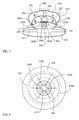
- FIG. 1 is a schematic structural view showing the lamp structure, according to the present invention
- FIG. 2 is a top view of FIG. 1 , which mainly consists of:
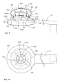
- FIG. 3 is a schematic structural view showing the heat dissipation structure (1020) being installed, and the annular arc-shaped airflow guide hole (1030) being provided for guiding the cold/hot airflow, according to the present invention
- FIG. 4 is a cross sectional view of FIG. 3 taken along an A-A line, which mainly consists of:
- FIG. 5 is a schematic structural view showing a first example wherein a heat dissipation structure (1020) being installed, and a recessed hole (1010) having a notch (1040) at top center and an annular arc-shaped airflow guide hole (1030) being provided for guiding the cold/hot airflow, according to the present invention
- FIG. 6 is a cross sectional view of FIG. 5 taken along a B-B line, which mainly consists of:
- FIG. 7 is a schematic structural view showing the heat dissipation structure (1020) being installed, and the annular arc-shaped airflow guide hole (1030) and a columnar body (1050) having inward-recessed top center being provided for guiding the cold/hot airflow
- FIG. 8 is a cross sectional view of FIG. 7 taken along a C-C line, which mainly consists of:
- the heat dissipating lamp device having electric axial turbine fan, disclosed from FIG. 1 to FIG. 8 can be further installed with an electric-driven light emitting lamp set (304) at the bottom of the heat dissipation structure (102) or the heat dissipation structure (1020), wherein:
- the heat dissipating lamp device having electric axial turbine fan, disclosed from FIG. 1 to FIG. 8 can be further installed with a secondary optical device (303) in the lamp housing (101), wherein:
- the heat dissipating lamp device having electric axial turbine fan, disclosed from FIG. 1 to FIG. 8 can be further installed with a light-pervious lampshade (302) on the lamp housing (101), wherein:
- the heat dissipating lamp device having electric axial turbine fan disclosed from FIG. 1 to FIG. 8 , can be further installed with a top portion covering net (301) at the outer periphery of the electric turbine axial fan (200), wherein:
- the heat dissipating lamp device having electric axial turbine fan, disclosed from FIG. 1 to FIG. 8 can be further installed with a temperature switch (305) on the heat dissipation structure (102) or the heat dissipation structure (1020), wherein:
- the lamp housing (101) is provided with a structure for being combined with an external support arm (10) for allowing the support arm (10) to be combined;
- FIG. 9 is a schematic structural view showing the lamp housing (101) being combined with an external support arm (10), according to one embodiment of the present invention
- FIG. 10 is a cross sectional view of FIG. 9 taken along a D-D line.
- the lamp housing (101) is provided with a structure for being combined with an external support rod (20) for allowing the support rod (20) to be combined;
- FIG. 11 is a schematic structural view showing the lamp housing (101) being combined with an external support rod (20), according to one embodiment of the present invention
- FIG. 12 is a cross sectional view of FIG. 11 taken along an E-E line.
- the top cover (1000) is provided with a partition structure (30) to be combined between the airflow passing the heat dissipation structure (102) or the heat dissipation structure (1020), and the airflow exhausted from the electric turbine axial fan (200);
- FIG. 13 is a schematic structural view showing the lamp housing (101) being combined with an external partition structure (30), according to one embodiment of the present invention.
- the heat dissipating lamp device having electric axial turbine fan, disclosed from FIG. 1 to FIG. 8 can be combined with a suspension device (40) for providing a suspension installation; wherein the suspended location combined with the suspension device (40) includes the annular arc-shape airflow guide surface (103), the top cover (1000) or the structural body of heat dissipating lamp device;
- FIG. 14 is a schematic structural view illustrating being combined with a suspension device (40), according to one embodiment of the present invention.
Landscapes
- Engineering & Computer Science (AREA)
- General Engineering & Computer Science (AREA)
- Structures Of Non-Positive Displacement Pumps (AREA)
- Arrangement Of Elements, Cooling, Sealing, Or The Like Of Lighting Devices (AREA)
- Non-Portable Lighting Devices Or Systems Thereof (AREA)
- Cooling Or The Like Of Electrical Apparatus (AREA)
Abstract
Description
- A conventional turbine axial fan thermally actuated or driven by wind power is equipped with a sealed top portion having plural axial exhaust blades arranged at intervals and stacked with equal inclined angles annularly installed at its periphery, the center thereof is downwardly extended with an axial airflow inlet port; when in operation, the plural exhaust blades provide a turbine axial airflow exhausting function, and the axial airflow inlet port introduces airflow during the rotation operation then the introduced airflow is exhausted to the surroundings; at present, a high power lamp set often adopts a heat dissipation housing made of a heat conductive material having a sealed top portion for preventing rainwater from entering; the present invention provides a turbine axial fan driven by an electric motor and installed on the top portion of a heat dissipation lamp housing, so when the electric turbine axial fan is operated, the airflow is concentrated from the outside of top portion of lamp housing, which is relatively hotter, of the sealed heat dissipation lamp housing towards the center, and leaded to upwardly enter an axial airflow inlet port formed at the bottom of the electric turbine axial fan, thereby being exhausted to the surroundings through the radially-arranged exhaust blades, thus when the present invention being applied in a high power lamp, e.g. a high power LED lamp set, a cooling effect by external cooling airflow can be provided to the top portion, which is relatively hotter, of the LED lamp housing; when external wind power drives the turbine axial fan, the loading of electric motor can be lowered so as to reduce the electric power outputted by the electric motor.
- The cooling for a conventional LED lamp housing includes natural air cooling or fan cooling, wherein the rainproof effect for the fan cooling is relatively harder to establish, it is yet to be seen a lamp housing having its top portion installed with a rainproof electric turbine axial fan structure in the market place.
- The present invention provides an electric turbine axial fan, which is rainproof and installed at the top portion of sealed heat dissipation lamp housing of a high power lamp, so when the electric turbine axial fan is operated, the airflow passes through the top portion of lamp housing, which is relatively hotter, of the sealed heat dissipation lamp housing and is concentrated towards the center, then leaded to upwardly enter an axial airflow inlet port formed at the bottom of the electric turbine axial fan, thereby being exhausted to the surroundings through radially-arranged exhaust blades, thus when the present invention being applied in a high power lamp, a cooling effect by the external cooling airflow can be provided to the top portion, which is relatively hotter; when external wind power drives the turbine axial fan, the loading of electric motor can be lowered so as to reduce the electric power outputted by the electric motor.
-
-
FIG. 1 is a schematic structural view showing the lamp structure, according to the present invention. -
FIG. 2 is a top view ofFIG. 1 . -
FIG. 3 is a schematic structural view showing a heat dissipation structure (1020) being installed, and an annular arc-shaped airflow guide hole (1030) being provided for guiding cold/hot airflow, according to the present invention. -
FIG. 4 is a cross sectional view ofFIG. 3 taken along an A-A line. -
FIG. 5 is a schematic structural view showing a heat dissipation structure (1020) being installed, and a recessed hole (1010) having a notch (1040) at top center and an annular arc-shaped airflow guide hole (1030) being provided for guiding cold/hot airflow, according to the present invention. -
FIG. 6 is a cross sectional view ofFIG. 5 taken along a B-B line. -
FIG. 7 is a schematic structural view showing the heat dissipation structure (1020) being installed, and the annular arc-shaped airflow guide hole (1030) and a columnar body (1050) having inward-recessed top center being provided for guiding cold/hot airflow. -
FIG. 8 is a cross sectional view ofFIG. 7 taken along a C-C line. -
FIG. 9 is a schematic structural view showing the lamp housing (101) being combined with an external support arm (10), according to one embodiment of the present invention. -
FIG. 10 is a cross sectional view ofFIG. 9 taken along a D-D line. -
FIG. 11 is a schematic structural view showing the lamp housing (101) being combined with an external support rod (20), according to one embodiment of the present invention. -
FIG. 12 is a cross sectional view ofFIG. 11 taken along an E-E line. -
FIG. 13 is a schematic structural view showing the lamp housing (101) being combined with an external partition structure (30), according to one embodiment of the present invention. -
FIG. 14 is a schematic structural view illustrating being combined with a suspension device (40), according to one embodiment of the present invention. -
- 10 :
- Support arm
- 20 :
- Support rod
- 30 :
- Partition structure
- 40 :
- Suspension device
- 101 :
- Lamp housing
- 1000 :
- Top cover
- 1010 :
- Recessed hole
- 102 1020 :
- Heat dissipation structure
- 103 :
- Annular arc-shape airflow guide surface
- 1030 :
- Annular arc-shaped airflow guide hole
- 104 :
- Top portion of heat dissipation structure
- 1040 :
- Notch
- 1050 :
- Columnar body
- 200 :
- electric turbine axial fan
- 202 :
- Electric motor
- 204 :
- Heat insulation member
- 206 :
- Rotation shaft
- 207 :
- Radially-arranged exhaust blade
- 208 :
- Axial fluid inlet port
- 209 :
- Sealed top cover
- 301 :
- Top portion covering net
- 302 :
- Light-pervious lampshade
- 303 :
- Secondary optical device
- 304 :
- Electric driven light emitting lamp set
- 305 :
- Temperature switch
- The cooling for a conventional LED lamp housing includes natural air cooling or fan cooling, wherein the rainproof effect for the fan cooling is relatively harder to establish, it is yet to be seen a lamp housing having its top portion installed with a rainproof electric turbine axial fan structure in the market place.
- A conventional turbine axial fan thermally actuated or driven by wind power is equipped with a sealed top portion having plural axial exhaust blades arranged at intervals and stacked with equal inclined angles annularly installed at its periphery, the center thereof is downwardly extended with an axial airflow inlet port; when in operation, the plural exhaust blades provide a turbine axial airflow exhausting function, and the axial airflow inlet port introduces airflow during the rotation operation then the introduced airflow is exhausted to the surroundings; at present, a high power lamp set often adopts a heat dissipation housing made of a heat conductive material having a sealed top portion for preventing rainwater from entering; the present invention provides a turbine axial fan driven by an electric motor and installed on the top portion of a heat dissipation lamp housing, so when the electric turbine axial fan is operated, the airflow is concentrated from the outside of top portion of lamp housing, which is relatively hotter, of the sealed heat dissipation lamp housing towards the center, and leaded to upwardly enter an axial airflow inlet port formed at the bottom of the electric turbine axial fan, thereby being exhausted to the surroundings through the radially-arranged exhaust blades, thus when the present invention being applied in a high power lamp, e.g. a high power LED lamp set, a cooling effect by external cooling airflow can be provided to the top portion, which is relatively hotter, of the LED lamp housing; when external wind power drives the turbine axial fan, the loading of electric motor can be lowered so as to reduce the electric power outputted by the electric motor.
-
FIG. 1 is a schematic structural view showing the lamp structure, according to the present invention, andFIG. 2 is a top view ofFIG. 1 , which mainly consists of: - --Lamp housing (101), heat dissipation structure (102): the lamp housing (101) is constituted by a bowl-shaped structure reversely disposed, and configured by a heat conductive member or non-heat conductive member, the top center thereof and the heat dissipation structure (102) formed in round shape or conical shape and having vertical radial blades are integrally formed or assembled with each other, the bottom of the heat dissipation structure (102) allows a LED or other lamps to be installed, and the lamp housing (101) is formed with an annular arc-shape airflow guide surface (103) along the periphery of the heat dissipation structure (102);
- --Electric turbine axial fan(200): constituted by a turbine driven by a built-in electric motor (202) and having radially-arranged exhaust blades (207), the bottom of the static part of electric motor is installed on the top portion (104) of heat dissipation structure (102) and spaced by a heat insulation member (204), a rotation shaft (206) of the rotary part of electric motor is upwardly extended for serving as a core shaft for driving the turbine having the radially-arranged exhaust blades (207), the bottom of the electric turbine axial fan (200) is formed with an axial fluid inlet port (208) for introducing the fluid passing the annular arc-shaped airflow guide surface (103) of the lamp housing (101) to pass through the periphery of the top of heat dissipation structure (102), then be exhausted to the surroundings through the radially-arranged exhaust blades (207), and the top of electric turbine axial fan (200) is provided with a sealed top cover (209) for providing protection to the electric motor (202);
-
FIG. 3 is a schematic structural view showing the heat dissipation structure (1020) being installed, and the annular arc-shaped airflow guide hole (1030) being provided for guiding the cold/hot airflow, according to the present invention, andFIG. 4 is a cross sectional view ofFIG. 3 taken along an A-A line, which mainly consists of: - --Lamp housing (101), heat dissipation structure (1020): the lamp housing (101) is constituted by a bowl-shaped structure reversely disposed, and configured by a heat conductive member or non-heat conductive member, the heat dissipation structure (1020) is configured by a high-performance heat conductive member, the top center thereof is formed in round or conical shape or other geometric shapes and having a downward-facing recessed hole (1010), and the periphery is installed with upward-facing radially-arranged vertical blades, for being combined with a top cover (1000) configured by a heat conductive member and having its exterior formed in a round, conical or other geometric shapes, so as to jointly constitute a heat dissipation structure with airflow guide hole and having the annular arc-shape airflow guide hole (1030), the heat dissipation structure (1020) and the lamp housing (101) are integrally formed or individually manufactured then assembled as one piece, the bottom of the heat dissipation structure (1020) allows a LED or other lamps to be installed, the top cover (1000) provides functions of guiding airflow, dissipating heat or being fastened to the exterior;
- --Electric turbine axial fan (200): constituted by a turbine driven by a built-in electric motor (202) and having radially-arranged exhaust blades (207), the bottom of the static part of electric motor is installed on the top portion (104) of heat dissipation structure (1020) and spaced by a heat insulation member (204), a rotation shaft (206) of the rotary part of electric motor is upwardly extended for serving as a core shaft for driving the turbine having the radially-arranged exhaust blades (207), so as to introduce the external airflow to pass through an axial fluid inlet port (208) of the annular arc-shape airflow guide hole (1030) of the heat dissipation structure (1020), then be exhausted to the surroundings through the radially-arranged exhaust blades (207), the top of electric turbine axial fan (200) is provided with a sealed top cover (209) for providing protection to the electric motor (202);
-
FIG. 5 is a schematic structural view showing a first example wherein a heat dissipation structure (1020) being installed, and a recessed hole (1010) having a notch (1040) at top center and an annular arc-shaped airflow guide hole (1030) being provided for guiding the cold/hot airflow, according to the present invention, andFIG. 6 is a cross sectional view ofFIG. 5 taken along a B-B line, which mainly consists of: - --Lamp housing (101), heat dissipation structure (1020): the lamp housing (101) is constituted by a bowl-shaped structure reversely disposed, and configured by a heat conductive member or non-heat conductive member, the heat dissipation structure (1020) is configured by a high-performance heat conductive member, the top center thereof is formed in round or conical shape or other geometric shapes and having a downward-facing recessed hole (1010) with its periphery formed with a notch (1040), the periphery is installed with upward-facing radially-arranged vertical blades, for being combined with a top cover (1000) configured by a heat conductive member and having its exterior formed in a round, conical or other geometric shapes, so as to jointly constitute a heat dissipation structure with airflow guide hole and having the annular arc-shape airflow guide hole (1030), the heat dissipation structure (1020) and the lamp housing (101) are integrally formed or individually manufactured then assembled as one piece, and the bottom of the heat dissipation structure (1020) allows a LED or other lamps to be installed, and the top cover (1000) provides functions of guiding airflow, dissipating heat or being fastened to the exterior;
- --Electric turbine axial fan (200): constituted by a turbine driven by a built-in electric motor (202) and having radially-arranged exhaust blades (207), the bottom of the static part of electric motor is installed on the top portion (104) of heat dissipation structure (1020) and spaced by a heat insulation member (204), a rotation shaft (206) of the rotary part of electric motor is upwardly extended for serving as a core shaft for driving the turbine having the radially-arranged exhaust blades (207), so as to introduce the external airflow to pass through the axial fluid inlet port (208) of the annular arc-shaped airflow guide hole (1030) of the heat dissipation structure (1020), then be exhausted to the surroundings through the radially-arranged exhaust blades (207), and the top of electric turbine axial fan (200) is provided with a sealed top cover (209) for providing protection to the electric motor (202);
-
FIG. 7 is a schematic structural view showing the heat dissipation structure (1020) being installed, and the annular arc-shaped airflow guide hole (1030) and a columnar body (1050) having inward-recessed top center being provided for guiding the cold/hot airflow, andFIG. 8 is a cross sectional view ofFIG. 7 taken along a C-C line, which mainly consists of: - --Lamp housing (101), heat dissipation structure (1020): the lamp housing (101) is constituted by a bowl-shaped structure reversely disposed, and configured by a heat conductive member or non-heat conductive member, the heat dissipation structure (1020) is configured by a high-performance heat conductive member, the top center thereof is formed in round or conical shape or other geometric shapes and having an inward-recessed columnar body (1050), the periphery is installed with upward-facing radially-arranged vertical blades, for being combined with a top cover (1000) configured by a heat conductive member and having its exterior formed in a round, conical or other geometric shapes, so as to jointly constitute a heat dissipation structure with airflow guide hole and having the annular arc-shape airflow guide hole (1030), the heat dissipation structure (1020) and the lamp housing (101) are integrally formed or individually manufactured then assembled as one piece, and the bottom of the heat dissipation structure (1020) allows a LED or other lamps to be installed, the top cover (1000) provides functions of guiding airflow, dissipating heat or being fastened to the exterior;
- --Electric turbine axial fan (200): constituted by a turbine driven by a built-in electric motor (202) and having radially-arranged exhaust blades (207), the bottom of the static part of electric motor is installed on the top portion (104) of heat dissipation structure (1020) and spaced by a heat insulation member (204), a rotation shaft (206) of the rotary part of electric motor is upwardly extended for serving as a core shaft for driving the turbine having the radially-arranged exhaust blades (207), so as to introduce the external airflow to pass through the axial fluid inlet port (208) of the annular arc-shaped airflow guide hole (1030) of the heat dissipation structure (1020), then be exhausted to the surroundings through the radially-arranged exhaust blades (207), and the top of electric turbine axial fan (200) is provided with a sealed top cover (209) for providing protection to the electric motor (202);
- The heat dissipating lamp device having electric axial turbine fan, disclosed from
FIG. 1 to FIG. 8 , can be further installed with an electric-driven light emitting lamp set (304) at the bottom of the heat dissipation structure (102) or the heat dissipation structure (1020), wherein: - --Electric-driven light emitting lamp set (304): constituted by one or more than one of the following electric-driven light emitting lamps, including:
- 1) DC light emitting diode;
- 2) AC light emitted diode;
- 3) Gaseous lamp set;
- 4) Fluorescent lamp;
- 5) Lamp bulb;
- The heat dissipating lamp device having electric axial turbine fan, disclosed from
FIG. 1 to FIG. 8 , can be further installed with a secondary optical device (303) in the lamp housing (101), wherein: - --Secondary optical device (303): constituted by a structural body having light reflection function, and annularly installed at the top periphery of a light emitting lamp set (304), thereby equipped with functional operations of reflecting, refracting and condensing or diffusing the optical energy of the electric-driven light emitting lamp set (304);
- The heat dissipating lamp device having electric axial turbine fan, disclosed from
FIG. 1 to FIG. 8 , can be further installed with a light-pervious lampshade (302) on the lamp housing (101), wherein: - --Light-pervious lampshade (302): constituted by a fixed structure and light-pervious glass for being combined at the lower end of the lamp housing (101) for protecting the electric-driven light emitting lamp set (304) without influencing the illumination performance thereof;
- The heat dissipating lamp device having electric axial turbine fan, disclosed from
FIG. 1 to FIG. 8 , can be further installed with a top portion covering net (301) at the outer periphery of the electric turbine axial fan (200), wherein: - --Top portion covering net (301): constituted by a net-shaped structure for covering and protecting the electric turbine axial fan (200) and secured on the lamp housing (101);
- The heat dissipating lamp device having electric axial turbine fan, disclosed from
FIG. 1 to FIG. 8 , can be further installed with a temperature switch (305) on the heat dissipation structure (102) or the heat dissipation structure (1020), wherein: - --Temperature switch (305): constituted by an electromechanical joint switch configured by electrical mechanic or dual metal sheets or memory alloy, or constituted by a solid-state switch device driven by thermistor or thermocouple, wherein one or more than one temperature switches (305) are installed at locations close to the location where the electric-driven light emitting lamp set (304) being installed on the heat dissipation structure (102) or the heat dissipation structure (1020), so when the temperature generated by the electric-driven light emitting lamp set (304) transmitted to the temperature switch (305) installed on the heat dissipation structure (102) or the heat dissipation structure (1020) exceeds a preset temperature value, all or part of the controlled power source of the electric-driven light emitting lamp set (304) is cut off for preventing the electric-driven light emitting lamp set (304) from overheating.
- In the heat dissipating lamp device having electric axial turbine fan disclosed from
FIG. 1 to FIG. 8 , the lamp housing (101) is provided with a structure for being combined with an external support arm (10) for allowing the support arm (10) to be combined; -
FIG. 9 is a schematic structural view showing the lamp housing (101) being combined with an external support arm (10), according to one embodiment of the present invention,FIG. 10 is a cross sectional view ofFIG. 9 taken along a D-D line. - In the heat dissipating lamp device having electric axial turbine fan disclosed from
FIG. 1 to FIG. 8 , the lamp housing (101) is provided with a structure for being combined with an external support rod (20) for allowing the support rod (20) to be combined; -
FIG. 11 is a schematic structural view showing the lamp housing (101) being combined with an external support rod (20), according to one embodiment of the present invention,FIG. 12 is a cross sectional view ofFIG. 11 taken along an E-E line. - In the heat dissipating lamp device having electric axial turbine fan disclosed from
FIG. 1 to FIG. 8 , the top cover (1000) is provided with a partition structure (30) to be combined between the airflow passing the heat dissipation structure (102) or the heat dissipation structure (1020), and the airflow exhausted from the electric turbine axial fan (200); -
FIG. 13 is a schematic structural view showing the lamp housing (101) being combined with an external partition structure (30), according to one embodiment of the present invention. - The heat dissipating lamp device having electric axial turbine fan, disclosed from
FIG. 1 to FIG. 8 , can be combined with a suspension device (40) for providing a suspension installation; wherein the suspended location combined with the suspension device (40) includes the annular arc-shape airflow guide surface (103), the top cover (1000) or the structural body of heat dissipating lamp device; -
FIG. 14 is a schematic structural view illustrating being combined with a suspension device (40), according to one embodiment of the present invention.
Claims (10)
- A heat dissipating lamp device having electric turbine axial fan, which provides a turbine axial fan driven by an electric motor and installed on the top portion of a heat dissipation lamp housing, so when the electric turbine axial fan is operated, the airflow is concentrated from the outside of top portion of lamp housing, which is relatively hotter, of the sealed heat dissipation lamp housing towards the center, and leaded to upwardly enter an axial airflow inlet port formed at the bottom of the electric turbine axial fan, thereby being exhausted to the surroundings through the radially-arranged exhaust blades, thus when the present invention being applied in a high power lamp, e.g. a high power LED lamp set, a cooling effect by external cooling airflow can be provided to the top portion, which is relatively hotter, of the LED lamp housing; when external wind power drives the turbine axial fan, the loading of electric motor can be lowered so as to reduce the electric power outputted by the electric motor, wherein it is mainly consists of:--Lamp housing (101), heat dissipation structure (102): the lamp housing (101) is constituted by a bowl-shaped structure reversely disposed, and configured by a heat conductive member or non-heat conductive member, the top center thereof and the heat dissipation structure (102) formed in round shape or conical shape and having vertical radial blades are integrally formed or assembled with each other, the bottom of the heat dissipation structure (102) allows a LED or other lamps to be installed, and the lamp housing (101) is formed with an annular arc-shape airflow guide surface (103) along the periphery of the heat dissipation structure (102);--Electric turbine axial fan(200): constituted by a turbine driven by a built-in electric motor (202) and having radially-arranged exhaust blades (207), the bottom of the static part of electric motor is installed on the top portion (104) of heat dissipation structure (102) and spaced by a heat insulation member (204), a rotation shaft (206) of the rotary part of electric motor is upwardly extended for serving as a core shaft for driving the turbine having the radially-arranged exhaust blades (207), the bottom of the electric turbine axial fan (200) is formed with an axial fluid inlet port (208) for introducing the fluid passing the annular arc-shaped airflow guide surface (103) of the lamp housing (101) to pass through the periphery of the top of heat dissipation structure (102), then be exhausted to the surroundings through the radially-arranged exhaust blades (207), and the top of electric turbine axial fan (200) is provided with a sealed top cover (209) for providing protection to the electric motor (202).
- A heat dissipating lamp device having electric turbine axial fan as claimed in claim 1, wherein the heat dissipation structure (1020) is further installed, and the annular arc-shaped airflow guide hole (1030) is provided for guiding the cold/hot airflow, which mainly consists of:--Lamp housing (101), heat dissipation structure (1020): the lamp housing (101) is constituted by a bowl-shaped structure reversely disposed, and configured by a heat conductive member or non-heat conductive member, the heat dissipation structure (1020) is configured by a high-performance heat conductive member, the top center thereof is formed in round or conical shape or other geometric shapes and having a downward-facing recessed hole (1010), and the periphery is installed with upward-facing radially-arranged vertical blades, for being combined with a top cover (1000) configured by a heat conductive member and having its exterior formed in a round, conical or other geometric shapes, so as to jointly constitute a heat dissipation structure with airflow guide hole and having the annular arc-shape airflow guide hole (1030), the heat dissipation structure (1020) and the lamp housing (101) are integrally formed or individually manufactured then assembled as one piece, the bottom of the heat dissipation structure (1020) allows a LED or other lamps to be installed, the top cover (1000) provides functions of guiding airflow, dissipating heat or being fastened to the exterior;--Electric turbine axial fan (200): constituted by a turbine driven by a built-in electric motor (202) and having radially-arranged exhaust blades (207), the bottom of the static part of electric motor is installed on the top portion (104) of heat dissipation structure (1020) and spaced by a heat insulation member (204), a rotation shaft (206) of the rotary part of electric motor is upwardly extended for serving as a core shaft for driving the turbine having the radially-arranged exhaust blades (207), so as to introduce the external airflow to pass through an axial fluid inlet port (208) of the annular arc-shape airflow guide hole (1030) of the heat dissipation structure (1020), then be exhausted to the surroundings through the radially-arranged exhaust blades (207), the top of electric turbine axial fan (200) is provided with a sealed top cover (209) for providing protection to the electric motor (202).
- A heat dissipating lamp device having electric turbine axial fan as claimed in claim 1, wherein a heat dissipation structure (1020) is further installed, and a recessed hole (1010) having a notch (1040) at top center and an annular arc-shaped airflow guide hole (1030) is provided for guiding the cold/hot airflow, which mainly consists of:--Lamp housing (101), heat dissipation structure (1020): the lamp housing (101) is constituted by a bowl-shaped structure reversely disposed, and configured by a heat conductive member or non-heat conductive member, the heat dissipation structure (1020) is configured by a high-performance heat conductive member, the top center thereof is formed in round or conical shape or other geometric shapes and having a downward-facing recessed hole (1010) with its periphery formed with a notch (1040), the periphery is installed with upward-facing radially-arranged vertical blades, for being combined with a top cover (1000) configured by a heat conductive member and having its exterior formed in a round, conical or other geometric shapes, so as to jointly constitute a heat dissipation structure with airflow guide hole and having the annular arc-shape airflow guide hole (1030), the heat dissipation structure (1020) and the lamp housing (101) are integrally formed or individually manufactured then assembled as one piece, the bottom of the heat dissipation structure (1020) allows a LED or other lamps to be installed, and the top cover (1000) provides functions of guiding airflow, dissipating heat or being fastened to the exterior;--Electric turbine axial fan (200): constituted by a turbine driven by a built-in electric motor (202) and having radially-arranged exhaust blades (207), the bottom of the static part of electric motor is installed on the top portion (104) of heat dissipation structure (1020) and spaced by a heat insulation member (204), a rotation shaft (206) of the rotary part of electric motor is upwardly extended for serving as a core shaft for driving the turbine having the radially-arranged exhaust blades (207), so as to introduce the external airflow to pass through the axial fluid inlet port (208) of the annular arc-shaped airflow guide hole (1030) of the heat dissipation structure (1020), then be exhausted to the surroundings through the radially-arranged exhaust blades (207), and the top of electric turbine axial fan (200) is provided with a sealed top cover (209) for providing protection to the electric motor (202).
- A heat dissipating lamp device having electric turbine axial fan as claimed in claim 1, wherein the heat dissipation structure (1020) is further installed, and the annular arc-shaped airflow guide hole (1030) and a columnar body (1050) having inward-recessed top center is provided for guiding the cold/hot airflow, which mainly consists of:--Lamp housing (101), heat dissipation structure (1020): the lamp housing (101) is constituted by a bowl-shaped structure reversely disposed, and configured by a heat conductive member or non-heat conductive member, the heat dissipation structure (1020) is configured by a high-performance heat conductive member, the top center thereof is formed in round or conical shape or other geometric shapes and having an inward-recessed columnar body (1050), the periphery is installed with upward-facing radially-arranged vertical blades, for being combined with a top cover (1000) configured by a heat conductive member and having its exterior formed in a round, conical or other geometric shapes, so as to jointly constitute a heat dissipation structure with airflow guide hole and having the annular arc-shape airflow guide hole (1030), the heat dissipation structure (1020) and the lamp housing (101) are integrally formed or individually manufactured then assembled as one piece, and the bottom of the heat dissipation structure (1020) allows a LED or other lamps to be installed, the top cover (1000) provides functions of guiding airflow, dissipating heat or being fastened to the exterior;--Electric turbine axial fan (200): constituted by a turbine driven by a built-in electric motor (202) and having radially-arranged exhaust blades (207), the bottom of the static part of electric motor is installed on the top portion (104) of heat dissipation structure (1020) and spaced by a heat insulation member (204), a rotation shaft (206) of the rotary part of electric motor is upwardly extended for serving as a core shaft for driving the turbine having the radially-arranged exhaust blades (207), so as to introduce the external airflow to pass through the axial fluid inlet port (208) of the annular arc-shaped airflow guide hole (1030) of the heat dissipation structure (1020), then be exhausted to the surroundings through the radially-arranged exhaust blades (207), and the top of electric turbine axial fan (200) is provided with a sealed top cover (209) for providing protection to the electric motor (202).
- A heat dissipating lamp device having electric turbine axial fan as claimed in any of claims 1∼4, wherein it is further installed with an electric-driven light emitting lamp set (304) at the bottom of the heat dissipation structure (102) or the heat dissipation structure (1020), wherein:--Electric-driven light emitting lamp set (304): constituted by one or more than one of the following electric-driven light emitting lamps, including:1) DC light emitting diode;2) AC light emitted diode;3) Gaseous lamp set;4) Fluorescent lamp;5) Lamp bulb.
- A heat dissipating lamp device having electric turbine axial fan as claimed in any of claims 1∼4, wherein it is further installed with a secondary optical device (303) in the lamp housing (141), wherein:--Secondary optical device (303): constituted by a structural body having light reflection function, and annularly installed at the top periphery of a light emitting lamp set (304), thereby equipped with functional operations of reflecting, refracting and condensing or diffusing the optical energy of the electric-driven light emitting lamp set (304).
- A heat dissipating lamp device having electric turbine axial fan as claimed in any of claims 1∼4, wherein it is further installed with a light-pervious lampshade (302) on the lamp housing (101), wherein:--Light-pervious lampshade (302): constituted by a fixed structure and light-pervious glass for being combined at the lower end of the lamp housing (101) for protecting the electric-driven light emitting lamp set (304) without influencing the illumination performance thereof.
- A heat dissipating lamp device having electric turbine axial fan as claimed in any of claims 1∼4, wherein it is further installed with a top portion covering net (301) at the outer periphery of the electric turbine axial fan (200), wherein:--Top portion covering net (301): constituted by a net-shaped structure for covering and protecting the electric turbine axial fan (200) and secured on the lamp housing (101).
- A heat dissipating lamp device having electric turbine axial fan as claimed in any of claims 1∼4, wherein it is further installed with a temperature switch (305) on the heat dissipation structure (102) or the heat dissipation structure (1020), wherein:--Temperature switch (305): constituted by an electromechanical joint switch configured by electrical mechanic or dual metal sheets or memory alloy, or constituted by a solid-state switch device driven by thermistor or thermocouple, wherein one or more than one temperature switches (305) are installed at locations close to the location where the electric-driven light emitting lamp set (304) being installed on the heat dissipation structure (102) or the heat dissipation structure (1020), so when the temperature generated by the electric-driven light emitting lamp set (304) transmitted to the temperature switch (305) installed on the heat dissipation structure (102) or the heat dissipation structure (1020) exceeds a preset temperature value, all or part of the controlled power source of the electric-driven light emitting lamp set (304) is cut off for preventing the electric-driven light emitting lamp set (304) from overheating.
- A heat dissipating lamp device having electric turbine axial fan as claimed in any of claims 1∼4, wherein it includes one or more than one of fastened means as follows:1) the lamp housing (101) is provided with a structure for being combined with an external support arm (10) for allowing the support arm (10) to be combined;2) the lamp housing (101) is provided with a structure for being combined with an external support rod (20) for allowing the support rod (20) to be combined;3) the top cover (1000) is provided with a partition structure (30) to be combined between the airflow passing the heat dissipation structure (102) or the heat dissipation structure (1020), and the airflow exhausted from the electric turbine axial fan (200);4) being combined with a suspension device (40) for providing a suspension installation; wherein the suspended location combined with the suspension device (40) includes the annular arc-shape airflow guide surface (103), the top cover (1000) or the structural body of heat dissipating lamp device.
Applications Claiming Priority (2)
| Application Number | Priority Date | Filing Date | Title |
|---|---|---|---|
| US201113233113A | 2011-09-15 | 2011-09-15 | |
| US13/279,388 US8529099B2 (en) | 2011-08-25 | 2011-10-24 | Heat dissipating lamp device having electric turbine axial fan |
Publications (2)
| Publication Number | Publication Date |
|---|---|
| EP2570724A2 true EP2570724A2 (en) | 2013-03-20 |
| EP2570724A3 EP2570724A3 (en) | 2014-06-04 |
Family
ID=46682725
Family Applications (1)
| Application Number | Title | Priority Date | Filing Date |
|---|---|---|---|
| EP12180304.3A Withdrawn EP2570724A3 (en) | 2011-09-15 | 2012-08-13 | Heat dissipating lamp device having electric turbine axial fan |
Country Status (7)
| Country | Link |
|---|---|
| US (1) | US8529099B2 (en) |
| EP (1) | EP2570724A3 (en) |
| JP (1) | JP6068888B2 (en) |
| CN (2) | CN202747193U (en) |
| AU (1) | AU2012216438A1 (en) |
| CA (1) | CA2786515C (en) |
| TW (2) | TWM468627U (en) |
Families Citing this family (19)
| Publication number | Priority date | Publication date | Assignee | Title |
|---|---|---|---|---|
| CN103124876B (en) * | 2010-08-06 | 2016-02-03 | 普司科Ict股份有限公司 | Optical semiconductor lighting device |
| US8529099B2 (en) * | 2011-08-25 | 2013-09-10 | Tai-Her Yang | Heat dissipating lamp device having electric turbine axial fan |
| TW201425811A (en) * | 2012-12-20 | 2014-07-01 | Chang Wah Electromaterials Inc | Solid-state illuminator with air passage |
| CN105318302A (en) * | 2014-07-24 | 2016-02-10 | 深圳市达特照明股份有限公司 | Waterproof protective device, LED lamp and assembling method of waterproof protective device |
| FR3044981B1 (en) * | 2015-12-14 | 2018-11-16 | Psa Automobiles Sa. | DEVICE FOR THE LIGHT SIGNALING OF A MOTOR VEHICLE |
| JP6389837B2 (en) * | 2016-02-01 | 2018-09-12 | 株式会社ライトボーイ | Floodlight |
| US9605840B1 (en) | 2016-05-23 | 2017-03-28 | Green Inova Lighting Technology (Shenzhen) Limited | LED kit |
| CN106481996B (en) * | 2016-11-22 | 2019-01-25 | 遵义市义阳光电有限公司 | A kind of LED light |
| CN106895309A (en) * | 2017-03-13 | 2017-06-27 | 广州科生环保科技有限公司 | A kind of LED street lamp of energy-saving radiating |
| CN108758370A (en) * | 2018-05-07 | 2018-11-06 | 浙江锐迪生光电有限公司 | A kind of active heat removal LED light based on gas flow purging technology |
| CN111911884B (en) * | 2019-05-09 | 2022-04-22 | 江苏秦龙汽车科技有限公司 | Daytime running lamp of LED front combined lamp |
| CN110715191B (en) * | 2019-11-18 | 2025-03-28 | 平流层复合水离子(深圳)有限公司 | Supercharged cooling air purification lamp |
| CN110894925B (en) * | 2019-12-02 | 2021-04-27 | 佛山市富赢电器有限公司 | Multifunctional LED lamp |
| US11032976B1 (en) * | 2020-03-16 | 2021-06-15 | Hgci, Inc. | Light fixture for indoor grow application and components thereof |
| CN113309994B (en) * | 2021-07-07 | 2023-12-29 | 鑫元科技(深圳)有限公司 | Energy-saving heat dissipation type LED lamp |
| CN115394139A (en) * | 2022-07-05 | 2022-11-25 | 济宁市技师学院 | Electrical engineering and automatic multifunctional practical training experimental device |
| CN116677972B (en) * | 2023-05-30 | 2024-04-12 | 苏州顺哲光电科技有限公司 | High-power semiconductor illuminator packaging structure |
| CN220776127U (en) * | 2023-08-31 | 2024-04-12 | 深圳市泛邦通用科技有限公司 | Ceiling fan lamp control circuit and ceiling fan lamp |
| CN118971492A (en) * | 2024-10-17 | 2024-11-15 | 上海上源泵业制造有限公司 | A motor rear bearing cooling fan blade and structure |
Family Cites Families (25)
| Publication number | Priority date | Publication date | Assignee | Title |
|---|---|---|---|---|
| US2258731A (en) * | 1938-04-14 | 1941-10-14 | Alexander E Blumenthal | Combination lamp and fan unit |
| GB9324030D0 (en) * | 1993-11-23 | 1994-01-12 | Smiths Industries Plc | Assemblies |
| US5458505A (en) * | 1994-02-03 | 1995-10-17 | Prager; Jay H. | Lamp cooling system |
| JP3017396B2 (en) * | 1994-05-18 | 2000-03-06 | 株式会社ピーエフユー | Heat sink device with fan |
| JPH10171362A (en) * | 1996-12-06 | 1998-06-26 | Hitachi Ltd | LCD projector |
| JP3054346U (en) * | 1998-05-26 | 1998-12-04 | 陳巖傅 | Radiator for CPU (Central Processing Unit) |
| JP3055076U (en) * | 1998-06-18 | 1998-12-22 | 麗淑 陳 | Lighting equipment with fan |
| CN2353947Y (en) * | 1998-11-05 | 1999-12-15 | 李明烈 | cooling fan |
| JP2001143523A (en) * | 1999-11-17 | 2001-05-25 | Mitsubishi Electric Corp | Light source device |
| US6511209B1 (en) * | 2001-10-02 | 2003-01-28 | Albert C. L. Chiang | Lighting fixture |
| JP4640313B2 (en) * | 2006-10-19 | 2011-03-02 | パナソニック電工株式会社 | LED lighting device |
| US7677770B2 (en) * | 2007-01-09 | 2010-03-16 | Lighting Science Group Corporation | Thermally-managed LED-based recessed down lights |
| CN101290106A (en) * | 2007-04-20 | 2008-10-22 | 胡凯 | Radiator for semiconductor LED lamp |
| TW200842239A (en) * | 2007-04-23 | 2008-11-01 | Zheng-Hu Chen | Multifunctional turbine wind power generator |
| US7959330B2 (en) * | 2007-08-13 | 2011-06-14 | Yasuki Hashimoto | Power LED lighting assembly |
| TWM346745U (en) * | 2008-07-25 | 2008-12-11 | Forcecon Technology Co Ltd | LED Lamp with heat-dissipation toward the terminal direction |
| US7911119B2 (en) * | 2008-10-27 | 2011-03-22 | Edison Opto Corporation | Heat dissipating device having turbine ventilator and LED lamp comprising the same |
| CN201306693Y (en) * | 2008-10-28 | 2009-09-09 | 艾笛森光电股份有限公司 | Heat dissipation device with turbine exhaust fan and LED lamp comprising heat dissipation device |
| US8240885B2 (en) * | 2008-11-18 | 2012-08-14 | Abl Ip Holding Llc | Thermal management of LED lighting systems |
| US20110110095A1 (en) * | 2009-10-09 | 2011-05-12 | Intematix Corporation | Solid-state lamps with passive cooling |
| EP2339234A1 (en) * | 2009-12-23 | 2011-06-29 | Micronel AG | Cooling device |
| CN103124876B (en) * | 2010-08-06 | 2016-02-03 | 普司科Ict股份有限公司 | Optical semiconductor lighting device |
| CN201836685U (en) * | 2010-09-17 | 2011-05-18 | 深圳市迈迪光电技术有限公司 | LED (light-emitting diode) bucket liner lamp |
| EP2718616B1 (en) * | 2011-06-09 | 2015-10-14 | Elumigen, LLC | Solid state lighting device using heat channels in a housing |
| US8529099B2 (en) * | 2011-08-25 | 2013-09-10 | Tai-Her Yang | Heat dissipating lamp device having electric turbine axial fan |
-
2011
- 2011-10-24 US US13/279,388 patent/US8529099B2/en not_active Expired - Fee Related
-
2012
- 2012-08-13 EP EP12180304.3A patent/EP2570724A3/en not_active Withdrawn
- 2012-08-13 CN CN2012204006893U patent/CN202747193U/en not_active Expired - Fee Related
- 2012-08-13 CN CN201210287720.1A patent/CN102997142B/en not_active Expired - Fee Related
- 2012-08-15 TW TW101215700U patent/TWM468627U/en unknown
- 2012-08-15 TW TW101129499A patent/TWI567335B/en not_active IP Right Cessation
- 2012-08-20 CA CA2786515A patent/CA2786515C/en not_active Expired - Fee Related
- 2012-08-24 AU AU2012216438A patent/AU2012216438A1/en not_active Abandoned
- 2012-09-11 JP JP2012199539A patent/JP6068888B2/en not_active Expired - Fee Related
Non-Patent Citations (1)
| Title |
|---|
| None |
Also Published As
| Publication number | Publication date |
|---|---|
| CA2786515A1 (en) | 2013-03-15 |
| CN102997142A (en) | 2013-03-27 |
| AU2012216438A1 (en) | 2013-04-04 |
| JP2013065557A (en) | 2013-04-11 |
| CN102997142B (en) | 2016-12-21 |
| CA2786515C (en) | 2019-11-05 |
| TWM468627U (en) | 2013-12-21 |
| CN202747193U (en) | 2013-02-20 |
| TW201319461A (en) | 2013-05-16 |
| TWI567335B (en) | 2017-01-21 |
| US8529099B2 (en) | 2013-09-10 |
| US20130051026A1 (en) | 2013-02-28 |
| JP6068888B2 (en) | 2017-01-25 |
| EP2570724A3 (en) | 2014-06-04 |
Similar Documents
| Publication | Publication Date | Title |
|---|---|---|
| US8529099B2 (en) | Heat dissipating lamp device having electric turbine axial fan | |
| CA2786252C (en) | Electric axial-flow fan having turbine type waterproof enclosure | |
| JP6131891B2 (en) | Lighting fixtures and heat sinks | |
| JP6041158B2 (en) | LED lamp | |
| RU2604590C2 (en) | Cooling system and light-emitting diode lamp, including such system | |
| JP5975303B2 (en) | LED lamp and heat sink used therefor | |
| JP5943242B2 (en) | LED lamp | |
| JP2012155920A (en) | Lighting system | |
| JP2012221697A (en) | Led lighting device | |
| WO2015122340A1 (en) | Led lamp and illumination apparatus using same | |
| JP6467462B2 (en) | LED lamp | |
| CN107339669B (en) | Lighting suite | |
| CN203656740U (en) | Led down lamp | |
| TWM462340U (en) | Electric axial-flow fan having turbine type waterproof enclosure | |
| CN201973507U (en) | Quick heat-radiating and explosion-proof LED lamp | |
| JP2016143573A (en) | LED lamp and its lighting equipment | |
| CN202598460U (en) | Forced air cooling heat dissipation structure for large-power street lamps | |
| KR20130124812A (en) | Led cooling apparatus using a cooler pan and cooler panels | |
| JP2011258537A (en) | Light-emitting diode lamp | |
| JP2012226960A (en) | Lighting fixture |
Legal Events
| Date | Code | Title | Description |
|---|---|---|---|
| PUAI | Public reference made under article 153(3) epc to a published international application that has entered the european phase |
Free format text: ORIGINAL CODE: 0009012 |
|
| AK | Designated contracting states |
Kind code of ref document: A2 Designated state(s): AL AT BE BG CH CY CZ DE DK EE ES FI FR GB GR HR HU IE IS IT LI LT LU LV MC MK MT NL NO PL PT RO RS SE SI SK SM TR |
|
| AX | Request for extension of the european patent |
Extension state: BA ME |
|
| PUAL | Search report despatched |
Free format text: ORIGINAL CODE: 0009013 |
|
| AK | Designated contracting states |
Kind code of ref document: A3 Designated state(s): AL AT BE BG CH CY CZ DE DK EE ES FI FR GB GR HR HU IE IS IT LI LT LU LV MC MK MT NL NO PL PT RO RS SE SI SK SM TR |
|
| AX | Request for extension of the european patent |
Extension state: BA ME |
|
| RIC1 | Information provided on ipc code assigned before grant |
Ipc: F21V 29/02 20060101ALI20140428BHEP Ipc: F21V 33/00 20060101AFI20140428BHEP Ipc: F21V 23/04 20060101ALN20140428BHEP Ipc: F21Y 101/02 20060101ALN20140428BHEP |
|
| 17P | Request for examination filed |
Effective date: 20140704 |
|
| RBV | Designated contracting states (corrected) |
Designated state(s): AL AT BE BG CH CY CZ DE DK EE ES FI FR GB GR HR HU IE IS IT LI LT LU LV MC MK MT NL NO PL PT RO RS SE SI SK SM TR |
|
| STAA | Information on the status of an ep patent application or granted ep patent |
Free format text: STATUS: THE APPLICATION HAS BEEN WITHDRAWN |
|
| 18W | Application withdrawn |
Effective date: 20150216 |