EP2570366B1 - Schnellmontagevorrichtung für Kanister - Google Patents
Schnellmontagevorrichtung für Kanister Download PDFInfo
- Publication number
- EP2570366B1 EP2570366B1 EP12004317.9A EP12004317A EP2570366B1 EP 2570366 B1 EP2570366 B1 EP 2570366B1 EP 12004317 A EP12004317 A EP 12004317A EP 2570366 B1 EP2570366 B1 EP 2570366B1
- Authority
- EP
- European Patent Office
- Prior art keywords
- arched
- housing
- piece
- quick
- mounting device
- Prior art date
- Legal status (The legal status is an assumption and is not a legal conclusion. Google has not performed a legal analysis and makes no representation as to the accuracy of the status listed.)
- Active
Links
Images

Classifications
-
- B—PERFORMING OPERATIONS; TRANSPORTING
- B65—CONVEYING; PACKING; STORING; HANDLING THIN OR FILAMENTARY MATERIAL
- B65D—CONTAINERS FOR STORAGE OR TRANSPORT OF ARTICLES OR MATERIALS, e.g. BAGS, BARRELS, BOTTLES, BOXES, CANS, CARTONS, CRATES, DRUMS, JARS, TANKS, HOPPERS, FORWARDING CONTAINERS; ACCESSORIES, CLOSURES, OR FITTINGS THEREFOR; PACKAGING ELEMENTS; PACKAGES
- B65D83/00—Containers or packages with special means for dispensing contents
- B65D83/14—Containers for dispensing liquid or semi-liquid contents by internal gaseous pressure, i.e. aerosol containers comprising propellant
- B65D83/16—Actuating means
- B65D83/26—Actuating means operating automatically, e.g. periodically
- B65D83/262—Actuating means operating automatically, e.g. periodically by clockwork, motor, electric or magnetic means operating without repeated human input
-
- B—PERFORMING OPERATIONS; TRANSPORTING
- B05—SPRAYING OR ATOMISING IN GENERAL; APPLYING FLUENT MATERIALS TO SURFACES, IN GENERAL
- B05B—SPRAYING APPARATUS; ATOMISING APPARATUS; NOZZLES
- B05B11/00—Single-unit hand-held apparatus in which flow of contents is produced by the muscular force of the operator at the moment of use
- B05B11/0005—Components or details
- B05B11/0008—Sealing or attachment arrangements between sprayer and container
-
- B—PERFORMING OPERATIONS; TRANSPORTING
- B65—CONVEYING; PACKING; STORING; HANDLING THIN OR FILAMENTARY MATERIAL
- B65D—CONTAINERS FOR STORAGE OR TRANSPORT OF ARTICLES OR MATERIALS, e.g. BAGS, BARRELS, BOTTLES, BOXES, CANS, CARTONS, CRATES, DRUMS, JARS, TANKS, HOPPERS, FORWARDING CONTAINERS; ACCESSORIES, CLOSURES, OR FITTINGS THEREFOR; PACKAGING ELEMENTS; PACKAGES
- B65D83/00—Containers or packages with special means for dispensing contents
- B65D83/14—Containers for dispensing liquid or semi-liquid contents by internal gaseous pressure, i.e. aerosol containers comprising propellant
- B65D83/16—Actuating means
- B65D83/20—Actuator caps
-
- B—PERFORMING OPERATIONS; TRANSPORTING
- B65—CONVEYING; PACKING; STORING; HANDLING THIN OR FILAMENTARY MATERIAL
- B65D—CONTAINERS FOR STORAGE OR TRANSPORT OF ARTICLES OR MATERIALS, e.g. BAGS, BARRELS, BOTTLES, BOXES, CANS, CARTONS, CRATES, DRUMS, JARS, TANKS, HOPPERS, FORWARDING CONTAINERS; ACCESSORIES, CLOSURES, OR FITTINGS THEREFOR; PACKAGING ELEMENTS; PACKAGES
- B65D83/00—Containers or packages with special means for dispensing contents
- B65D83/14—Containers for dispensing liquid or semi-liquid contents by internal gaseous pressure, i.e. aerosol containers comprising propellant
- B65D83/38—Details of the container body
- B65D83/388—Details of the container body with means for suspending the aerosol container
-
- B—PERFORMING OPERATIONS; TRANSPORTING
- B05—SPRAYING OR ATOMISING IN GENERAL; APPLYING FLUENT MATERIALS TO SURFACES, IN GENERAL
- B05B—SPRAYING APPARATUS; ATOMISING APPARATUS; NOZZLES
- B05B15/00—Details of spraying plant or spraying apparatus not otherwise provided for; Accessories
- B05B15/60—Arrangements for mounting, supporting or holding spraying apparatus
-
- B—PERFORMING OPERATIONS; TRANSPORTING
- B05—SPRAYING OR ATOMISING IN GENERAL; APPLYING FLUENT MATERIALS TO SURFACES, IN GENERAL
- B05B—SPRAYING APPARATUS; ATOMISING APPARATUS; NOZZLES
- B05B9/00—Spraying apparatus for discharge of liquids or other fluent material, without essentially mixing with gas or vapour
- B05B9/03—Spraying apparatus for discharge of liquids or other fluent material, without essentially mixing with gas or vapour characterised by means for supplying liquid or other fluent material
- B05B9/04—Spraying apparatus for discharge of liquids or other fluent material, without essentially mixing with gas or vapour characterised by means for supplying liquid or other fluent material with pressurised or compressible container; with pump
- B05B9/08—Apparatus to be carried on or by a person, e.g. of knapsack type
- B05B9/0805—Apparatus to be carried on or by a person, e.g. of knapsack type comprising a pressurised or compressible container for liquid or other fluent material
-
- B—PERFORMING OPERATIONS; TRANSPORTING
- B65—CONVEYING; PACKING; STORING; HANDLING THIN OR FILAMENTARY MATERIAL
- B65D—CONTAINERS FOR STORAGE OR TRANSPORT OF ARTICLES OR MATERIALS, e.g. BAGS, BARRELS, BOTTLES, BOXES, CANS, CARTONS, CRATES, DRUMS, JARS, TANKS, HOPPERS, FORWARDING CONTAINERS; ACCESSORIES, CLOSURES, OR FITTINGS THEREFOR; PACKAGING ELEMENTS; PACKAGES
- B65D83/00—Containers or packages with special means for dispensing contents
- B65D83/14—Containers for dispensing liquid or semi-liquid contents by internal gaseous pressure, i.e. aerosol containers comprising propellant
- B65D83/40—Closure caps
Definitions
- the present invention relates to a quick-mounting device that can quickly and conveniently mount a canister for spraying a mist of an agent, such as air fresheners, disinfectants, detergents, cosmetics, insect repellents or similar substances.
- an agent such as air fresheners, disinfectants, detergents, cosmetics, insect repellents or similar substances.
- a conventional spray device for aromatic liquid is provided with a hinged clamp that can clamp a neck of a canister.
- the spray device can be pressed to release a mist of an aromatic agent to allow a room full of good smell to overcome the original odor of the room.
- the hinged clamp can be opened again to allow the neck of an exhausted canister to be released from the clamp.
- some clamps cannot be opened more than 60 degrees, and thus the user cannot clearly see the coupling status of a canister, so that the replacement is not easy and cannot be accomplished in one operation.
- the applicant has contrive a quick-mounting device that can quickly and conveniently dismount an exhausted canister and mount a new canister for spraying.
- the primary object of the present invention is to provide a quick-mounting device that can mount a canister quickly and conveniently.
- the quick-mounting device is implemented to comprise a housing and an adjustment means.
- the housing defines a recess at a top thereof and a hollow space therein, the recess being defined by a circumferential surface and a bottom surface.
- the housing is sealed with a cover that defines a through hole at a center thereof
- the adjustment means includes two arched pieces and a control piece.
- the arched pieces are placed in the recess of the housing to define an opening therebetween, wherein the opening communicates with the through hole of the cover and the hollow space of the housing.
- the control piece has a pusher and is placed on top of the arched pieces to engage with two ends of each arched piece.
- Each arched piece is provided with a spring at an external side thereof intermediate of the two ends to be elastically engaged with the housing. Thereby, the pusher of the control piece of the adjustment means can be pressed to have the two arched pieces moved outwardly to change the dimension of the opening defined by the two arched pieces so as to mount a canister.
- the housing is defined with a first pair of opposing recesses and a second pair of opposing recesses, the first pair of opposing recesses being located at an orientation about 90 degrees relative to the second pair of opposing recesses.
- the control piece is according to the invention formed into a generally annular piece having two opposing projections, one of which is formed with the pusher, each projection being provided with an engaging protrusion on a bottom surface thereof.
- Each of the two ends of each arched piece is formed with a sloping surface.
- Each of the arched pieces is formed with two protrusions and a boss therebetween at an external side intermediate of the two ends for engaging with a corresponding spring.
- each engaging protrusion of the control piece of the adjustment means has two sides formed into a general V-shape for mating with two corresponding slopping surfaces respectively on the two arched pieces
- each arched piece of the adjustment means is formed with a sharp edge along an internal side thereof
- the bottom surface of the recess of the housing is defined with multiple grooves to be inserted with protrusions, which are formed on bottom surfaces of the arched pieces.
- the housing defines a plurality of first holes on a top thereof, and the cover defines a plurality of second holes corresponding to the first holes, so that the cover can be sealed with the housing by using fastening members through the first and second holes.
- two opposing lugs are provided on the cover across the through hole of the cover.
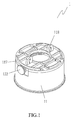
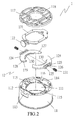
- the quick mounting device 1 comprises a housing 11 and an adjustment means 12.
- the housing 11 defines a recess 112 at a top thereof and a hollow space 111 therein, the recess 112 being defined by a circumferential surface and a bottom surface.
- the circumferential surface of the recess 112 of the housing 11 is defined with a first pair of opposing recesses 113, 114, and a second pair of opposing recesses 115, the first pair of opposing recesses 113, 114 being located at an orientation about 90 degrees relative to the second pair of opposing recesses 115.
- the line formed by the first pair of the opposing recesses 113, 114 is perpendicular to the line formed by the second pair of the opposing recesses 115.
- the bottom surface of the recess 112 of the housing 11 is defined with multiple grooves 116.
- the housing 11 is sealed with a cover 117 that defines a through hole at a center thereof
- the housing 11 defines a plurality of first holes on a top thereof, and the cover 117 defines a plurality of second holes corresponding to the first holes, so that the cover 117 can be sealed with the housing 11 by using fastening members through the first and second holes.
- two opposing lugs 118 are provided on the cover 117 across the through hole of the cover 117.
- the adjustment means 12 includes two arched pieces 124 and a control piece 121.
- the arched pieces 124 are placed in the recess 112 of the housing 11 to define an opening therebetween, wherein the opening communicates with the through hole of the cover 117 and the hollow space 111 of the housing 11.
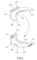
- the control piece 121 has a pusher 122 and is placed on top of the arched pieces 124 to engage with two ends of each arched piece 124, each arched piece 124 being provided with a spring 131 at an external side thereof intermediate of the two ends to be elastically engaged with the housing 11. As shown in FIGS. 3 and 4 , the two ends of each arched piece 124 are respectively formed with sloping surfaces 127, 128.
- Each of the arched pieces 124 is formed with two protrusions 125 and a boss 126 between the two protrusions 125 at the external side intermediate of the two ends for engaging with a corresponding spring 131.
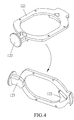
- the control piece 121 is formed into a generally annular piece having two opposing projections, one of which is formed with the pusher 122, which has a large area.
- the control piece 121 has a central opening.
- Each projection is provided with an engaging protrusion 123 at a bottom surface thereof.
- Each of the engaging portions 123 has two sides formed into a general V-shape for mating with two corresponding slopping surfaces respectively on the two arched pieces 124.
- each arched piece 124 of the adjustment means 12 is formed with protrusions 129 on a bottom surface thereof to be inserted into the grooves 116 of the housing 11.
- Each arched piece 124 of the adjustment means 12 is formed with a sharp edge 130 along an internal side thereof
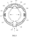
- the sharp edges 130 of the arched pieces 124 are located to face to each other; the spring 131 is mounted around the boss 126; the control piece 121 is placed on top of the two arched pieces 124, wherein the sharp edges 130 extend to partly cover the central opening of the control piece 121 (see FIG 5 ). Also the protrusions 123 are placed to contact with the sloping surfaces 127, 128 by their two sides formed into a general V-shape. As shown in FIG 5 , the control piece 121 of the adjustment means 12 is placed in the recess 112 of the housing 11, wherein the two projections (one with the pusher 122) are placed in the recesses 113, 114.
- the protrusions 129 of the two arched pieces 124 are placed in the grooves 116 defined in the bottom surface of the recess 112.
- the spring 131 and the protrusions 125 are placed in the recesses 115 defined in the circumferential surface of the recess 112 of the housing 11.
- the pusher 122 of the control piece 121 of the adjustment means 12 can be pressed to overcome the compressional force of each spring 131 to have the two arched pieces 124 moved outwardly via the protrusions 123 pushing the sloping surfaces 127, 128 so as to change the dimension of the opening defined by the sharp edges 130 of the two arched pieces 124.
- this movement happens outwardly of the two arched pieces 124 by a mutual parallel movement, which causes the opening to become consistent and thereby achieves a complete opening, even by a slight affection from the pusher 122 in the direction of the arrow.
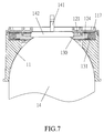
- a user may press the pusher 122 to allow the generally V-shaped protrusion 123 to push the sloping surfaces 127, 128 to move the two arched piece 124 outwardly so that the canister 14 can be fitted in the housing 11 from the bottom. Thereafter, the user may release the pusher 122 to allow the springs 131 to restore to their original positions so that the sharp edges 130 of the arched pieces 124 can clamp a neck 142 of the canister 14 so that the canister 14 can be mounted quickly and properly. Similarly, the canister 14 can be quickly dismounted in the same manner.
- the present invention has the following advantages over the prior art.
Landscapes
- Chemical & Material Sciences (AREA)
- Dispersion Chemistry (AREA)
- Engineering & Computer Science (AREA)
- Mechanical Engineering (AREA)
- Casings For Electric Apparatus (AREA)
- Supplying Secondary Fuel Or The Like To Fuel, Air Or Fuel-Air Mixtures (AREA)
- Connection Of Plates (AREA)
- Clamps And Clips (AREA)
Claims (6)
- Schnellmontageeinrichtung (1) für Kanister (14), umfassend:ein Gehäuse (12), das an einer Oberseite davon eine Ausnehmung (112) sowie einen hohlen Raum (111) darin definiert, wobei die Ausnehmung durch eine Umfangsfläche und eine Bodenfläche definiert ist, wobei das Gehäuse mit einer Abdeckung (117) abgedichtet ist, die an einer Mitte davon ein Durchgangsloch definiert; undein Einstellmittel (12) umfassend zwei gekrümmte Teile (124) und ein Steuerteil (121), wobei die gekrümmten Teile in der Ausnehmung des Gehäuses platziert sind, um dazwischen eine Öffnung zu definieren, wobei die Öffnung mit dem Durchgangsloch der Abdeckung und dem hohlen Raum des Gehäuses kommuniziert, wobei das Steuerteil einen Drücker (122) umfasst und oben auf den gekrümmten Teilen (124) platziert ist, um mit zwei Enden jedes der gekrümmten Teile in Eingriff zu treten,wobei jedes gekrümmte Teil an einer Außenseite davon zwischen den beiden Enden mit einer Feder (131) versehen ist, um elastisch mit dem Gehäuse in Eingriff zu treten; wodurch der Drücker (122) des Steuerteils (121) des Einstellmittels (12) gedrückt werden kann, so dass sich zwei gekrümmte Teile nach außen bewegen, um die Abmessung der Öffnung, die durch die beiden gekrümmten Teile definiert ist, zu ändern, dadurch gekennzeichnet, dass das Steuerteil (121) in ein im Wesentlichen ringförmiges Teil mit zwei gegenüberliegenden Auskragungen gebildet ist, von denen eine mit dem Drücker (122) gebildet ist, wobei jedeAuskragungan einer Bodenfläche davon mit einem in Eingriff tretenden Vorsprung (123) versehen ist; und wobei jedes der beiden Enden jedes gekrümmten Teils (124) mit einer abgeschrägten Fläche (127, 128) gebildet ist, wobei jedes der gekrümmten Teile an einer Außenseite zwischen den beiden Enden mit zwei Vorsprüngen(125) und einem runden Vorsprung (126) dazwischen zum Eingreifen mit einer entsprechenden Feder (131) gebildet ist.
- Schnellmontageeinrichtung für Kanister nach Anspruch 1, dadurch gekennzeichnet, dass jeder in Eingriff tretendeVorsprung(123) des Steuerteils (121) des Einstellmittels (12) zwei Seiten aufweist, die in eine im Wesentlichen V-artige Form gebildet sind, um mit zwei entsprechenden abgeschrägten Flächen (127, 128) jeweils an den beiden gekrümmten Teilen (124) zusammenzupassen.
- Schnellmontageeinrichtung für Kanister nach einem der vorstehenden Ansprüche, dadurch gekennzeichnet, dass jedes gekrümmte Teil (124) des Einstellmittels entlang einer inneren Seite davon mit einem scharfen Rand (130) gebildet ist.
- Schnellmontageeinrichtung für Kanister nach einem der vorstehenden Ansprüche, dadurch gekennzeichnet, dass die Bodenfläche der Ausnehmung des Gehäuses (11) mit mehreren Nuten (116) definiert ist, in die Vorsprünge (129), die an den Bodenflächen der gekrümmten Teile (124) gebildet sind, eingeführt werden.
- Schnellmontageeinrichtung für Kanister nach einem der vorstehenden Ansprüche, dadurch gekennzeichnet, dass das Gehäuse (11) an einer Oberseite davon eine Mehrzahl erster Löcher definiert und dass die Abdeckung (117) eine Mehrzahl zweiter Löcher definiert, die mit den ersten Löchern korrespondieren, so dass die Abdeckung mit dem Gehäuse abgedichtet werden kann, indem Befestigungselemente durch die ersten und zweiten Löcher verwendet werden.
- Schnellmontageeinrichtung für Kanister nach einem der vorstehenden Ansprüche, dadurch gekennzeichnet, dass an der Abdeckung (117) quer über das Durchgangsloch der Abdeckung zwei gegenüberliegende Ansätze (118) vorgesehen sind.
Applications Claiming Priority (1)
| Application Number | Priority Date | Filing Date | Title |
|---|---|---|---|
| US13/236,609 US8857776B2 (en) | 2011-09-19 | 2011-09-19 | Quick-mounting device for canister |
Publications (3)
| Publication Number | Publication Date |
|---|---|
| EP2570366A2 EP2570366A2 (de) | 2013-03-20 |
| EP2570366A3 EP2570366A3 (de) | 2014-04-16 |
| EP2570366B1 true EP2570366B1 (de) | 2016-08-10 |
Family
ID=46298197
Family Applications (1)
| Application Number | Title | Priority Date | Filing Date |
|---|---|---|---|
| EP12004317.9A Active EP2570366B1 (de) | 2011-09-19 | 2012-06-06 | Schnellmontagevorrichtung für Kanister |
Country Status (2)
| Country | Link |
|---|---|
| US (1) | US8857776B2 (de) |
| EP (1) | EP2570366B1 (de) |
Families Citing this family (4)
| Publication number | Priority date | Publication date | Assignee | Title |
|---|---|---|---|---|
| BE1022751B1 (nl) * | 2014-04-17 | 2016-08-29 | Rapidfit | Snel losmaakmechanisme voor onlosmaakbare klemmen |
| CN105486188A (zh) * | 2015-10-30 | 2016-04-13 | 中信戴卡股份有限公司 | 一种用于测量背镗刀尺寸的装置及方法 |
| WO2018038686A1 (en) * | 2016-08-23 | 2018-03-01 | Karaman Nurettin | Foam dispenser |
| EP4561760A1 (de) * | 2022-07-27 | 2025-06-04 | The Procter & Gamble Company | Flüssigkeitsabgabesystem, komponenten und merkmale davon sowie verfahren zur verwendung davon |
Family Cites Families (13)
| Publication number | Priority date | Publication date | Assignee | Title |
|---|---|---|---|---|
| GB361195A (en) * | 1931-02-02 | 1931-11-19 | Archer Alfred Jewell | Improvements in and relating to suspension of milk delivery bottles or the like containers |
| US3661300A (en) * | 1969-10-02 | 1972-05-09 | Gillette Co | Dispensing package |
| US3863814A (en) * | 1973-11-01 | 1975-02-04 | Jewel J Shelton | Safety cap for aerosol cans |
| DE2444245B2 (de) * | 1974-09-16 | 1976-09-30 | Armaturenfabrik Hermann Voss, 5290 Wipperfürth | Schlauchkupplung |
| DE19545226C1 (de) * | 1995-12-05 | 1997-06-19 | Boehringer Ingelheim Int | Sperrspannwerk für einen federbetätigten Abtrieb |
| US6216925B1 (en) * | 1999-06-04 | 2001-04-17 | Multi-Vet Ltd. | Automatic aerosol dispenser |
| TW447375U (en) * | 2000-08-09 | 2001-07-21 | Jang Shiue Chin | Fast clamping device for filtering core of engine oil |
| US6840461B1 (en) * | 2003-10-03 | 2005-01-11 | Whitmire Micro-Gen Research Laboratories, Inc. | Adapter clamp for aerosol can |
| CN101108685B (zh) * | 2006-07-20 | 2012-06-06 | 丰民金属工业股份有限公司 | 可快速夹固喷雾罐的夹固机构 |
| TW200811401A (en) * | 2006-08-29 | 2008-03-01 | Jian-Nan Chen | Gas torch nozzle with fast assembling structure |
| US7985068B2 (en) * | 2007-05-04 | 2011-07-26 | Irwin Industrial Tool Company | Gas appliance |
| KR20120060780A (ko) * | 2009-04-28 | 2012-06-12 | 바스프 코포레이션 | 발포성 살충제 조성물 |
| US8550413B2 (en) * | 2010-04-29 | 2013-10-08 | Hach Company | Self-centering vial clamp |
-
2011
- 2011-09-19 US US13/236,609 patent/US8857776B2/en active Active
-
2012
- 2012-06-06 EP EP12004317.9A patent/EP2570366B1/de active Active
Also Published As
| Publication number | Publication date |
|---|---|
| EP2570366A3 (de) | 2014-04-16 |
| US20130068920A1 (en) | 2013-03-21 |
| EP2570366A2 (de) | 2013-03-20 |
| US8857776B2 (en) | 2014-10-14 |
Similar Documents
| Publication | Publication Date | Title |
|---|---|---|
| EP2570366B1 (de) | Schnellmontagevorrichtung für Kanister | |
| JP5465869B2 (ja) | 替刃式剃刀 | |
| CA2970543C (en) | Container with sealable lid | |
| USD515927S1 (en) | Container | |
| USD536434S1 (en) | Aromatic vaporizer | |
| USD522642S1 (en) | Air freshener | |
| US11684222B2 (en) | Wipes dispensing canisters and wipes dispensing canister mounting brackets | |
| JP3615186B2 (ja) | 一方の表面によって組立てることのできる2つの室によって形成された容器 | |
| USD543091S1 (en) | Cover plate | |
| USD971376S1 (en) | Water purifier | |
| US7214898B1 (en) | Cover for light switch | |
| US11309148B2 (en) | Weatherproof decorator cover with positive indicator | |
| US11179489B2 (en) | Scent diffuser and scent diffusion device incorporating such a diffuser | |
| USD532902S1 (en) | Ceiling fan housing | |
| USD947346S1 (en) | Air purifier | |
| USD523951S1 (en) | Ceiling fan housing | |
| WO2007020593A3 (en) | Ergonomic dispenser | |
| USD969288S1 (en) | Air purifier | |
| CA2637605C (en) | Spray dispensers | |
| USD542399S1 (en) | Ionic air purifier | |
| US20210198034A1 (en) | Holder and substance container for treatment of waste in garbage bin | |
| USD552545S1 (en) | Electric contactor | |
| USD944747S1 (en) | Active cover plate contact | |
| USD535383S1 (en) | Ceiling fan housing | |
| USD524655S1 (en) | Tin and lid combination |
Legal Events
| Date | Code | Title | Description |
|---|---|---|---|
| PUAI | Public reference made under article 153(3) epc to a published international application that has entered the european phase |
Free format text: ORIGINAL CODE: 0009012 |
|
| AK | Designated contracting states |
Kind code of ref document: A2 Designated state(s): AL AT BE BG CH CY CZ DE DK EE ES FI FR GB GR HR HU IE IS IT LI LT LU LV MC MK MT NL NO PL PT RO RS SE SI SK SM TR |
|
| AX | Request for extension of the european patent |
Extension state: BA ME |
|
| PUAL | Search report despatched |
Free format text: ORIGINAL CODE: 0009013 |
|
| AK | Designated contracting states |
Kind code of ref document: A3 Designated state(s): AL AT BE BG CH CY CZ DE DK EE ES FI FR GB GR HR HU IE IS IT LI LT LU LV MC MK MT NL NO PL PT RO RS SE SI SK SM TR |
|
| AX | Request for extension of the european patent |
Extension state: BA ME |
|
| RIC1 | Information provided on ipc code assigned before grant |
Ipc: F16L 37/00 20060101ALI20140313BHEP Ipc: B65D 83/40 20060101ALI20140313BHEP Ipc: B65D 83/20 20060101ALI20140313BHEP Ipc: B05B 15/06 20060101ALI20140313BHEP Ipc: B05B 11/00 20060101ALI20140313BHEP Ipc: B05B 9/08 20060101ALN20140313BHEP Ipc: B65D 83/26 20060101AFI20140313BHEP Ipc: B65D 83/38 20060101ALN20140313BHEP |
|
| 17P | Request for examination filed |
Effective date: 20141016 |
|
| RAX | Requested extension states of the european patent have changed |
Extension state: ME Payment date: 20141016 Extension state: BA Payment date: 20141016 |
|
| RBV | Designated contracting states (corrected) |
Designated state(s): AL AT BE BG CH CY CZ DE DK EE ES FI FR GB GR HR HU IE IS IT LI LT LU LV MC MK MT NL NO PL PT RO RS SE SI SK SM TR |
|
| RIC1 | Information provided on ipc code assigned before grant |
Ipc: B65D 83/26 20060101AFI20160211BHEP Ipc: B65D 83/40 20060101ALI20160211BHEP Ipc: B05B 11/00 20060101ALI20160211BHEP Ipc: B65D 83/20 20060101ALI20160211BHEP Ipc: B05B 15/06 20060101ALI20160211BHEP Ipc: F16L 37/00 20060101ALI20160211BHEP Ipc: B05B 9/08 20060101ALN20160211BHEP Ipc: B65D 83/38 20060101ALN20160211BHEP |
|
| GRAP | Despatch of communication of intention to grant a patent |
Free format text: ORIGINAL CODE: EPIDOSNIGR1 |
|
| RIC1 | Information provided on ipc code assigned before grant |
Ipc: B65D 83/26 20060101AFI20160304BHEP Ipc: B65D 83/38 20060101ALN20160304BHEP Ipc: B65D 83/40 20060101ALI20160304BHEP Ipc: B05B 15/06 20060101ALI20160304BHEP Ipc: B05B 9/08 20060101ALN20160304BHEP Ipc: F16L 37/00 20060101ALI20160304BHEP Ipc: B65D 83/20 20060101ALI20160304BHEP Ipc: B05B 11/00 20060101ALI20160304BHEP |
|
| INTG | Intention to grant announced |
Effective date: 20160321 |
|
| GRAS | Grant fee paid |
Free format text: ORIGINAL CODE: EPIDOSNIGR3 |
|
| GRAA | (expected) grant |
Free format text: ORIGINAL CODE: 0009210 |
|
| AK | Designated contracting states |
Kind code of ref document: B1 Designated state(s): AL AT BE BG CH CY CZ DE DK EE ES FI FR GB GR HR HU IE IS IT LI LT LU LV MC MK MT NL NO PL PT RO RS SE SI SK SM TR |
|
| AX | Request for extension of the european patent |
Extension state: BA ME |
|
| REG | Reference to a national code |
Ref country code: GB Ref legal event code: FG4D |
|
| REG | Reference to a national code |
Ref country code: CH Ref legal event code: EP Ref country code: AT Ref legal event code: REF Ref document number: 818771 Country of ref document: AT Kind code of ref document: T Effective date: 20160815 |
|
| REG | Reference to a national code |
Ref country code: IE Ref legal event code: FG4D |
|
| REG | Reference to a national code |
Ref country code: DE Ref legal event code: R096 Ref document number: 602012021343 Country of ref document: DE |
|
| REG | Reference to a national code |
Ref country code: LT Ref legal event code: MG4D |
|
| REG | Reference to a national code |
Ref country code: NL Ref legal event code: MP Effective date: 20160810 |
|
| REG | Reference to a national code |
Ref country code: AT Ref legal event code: MK05 Ref document number: 818771 Country of ref document: AT Kind code of ref document: T Effective date: 20160810 |
|
| PG25 | Lapsed in a contracting state [announced via postgrant information from national office to epo] |
Ref country code: IS Free format text: LAPSE BECAUSE OF FAILURE TO SUBMIT A TRANSLATION OF THE DESCRIPTION OR TO PAY THE FEE WITHIN THE PRESCRIBED TIME-LIMIT Effective date: 20161210 Ref country code: FI Free format text: LAPSE BECAUSE OF FAILURE TO SUBMIT A TRANSLATION OF THE DESCRIPTION OR TO PAY THE FEE WITHIN THE PRESCRIBED TIME-LIMIT Effective date: 20160810 Ref country code: LT Free format text: LAPSE BECAUSE OF FAILURE TO SUBMIT A TRANSLATION OF THE DESCRIPTION OR TO PAY THE FEE WITHIN THE PRESCRIBED TIME-LIMIT Effective date: 20160810 Ref country code: HR Free format text: LAPSE BECAUSE OF FAILURE TO SUBMIT A TRANSLATION OF THE DESCRIPTION OR TO PAY THE FEE WITHIN THE PRESCRIBED TIME-LIMIT Effective date: 20160810 Ref country code: RS Free format text: LAPSE BECAUSE OF FAILURE TO SUBMIT A TRANSLATION OF THE DESCRIPTION OR TO PAY THE FEE WITHIN THE PRESCRIBED TIME-LIMIT Effective date: 20160810 Ref country code: NO Free format text: LAPSE BECAUSE OF FAILURE TO SUBMIT A TRANSLATION OF THE DESCRIPTION OR TO PAY THE FEE WITHIN THE PRESCRIBED TIME-LIMIT Effective date: 20161110 Ref country code: IT Free format text: LAPSE BECAUSE OF FAILURE TO SUBMIT A TRANSLATION OF THE DESCRIPTION OR TO PAY THE FEE WITHIN THE PRESCRIBED TIME-LIMIT Effective date: 20160810 Ref country code: NL Free format text: LAPSE BECAUSE OF FAILURE TO SUBMIT A TRANSLATION OF THE DESCRIPTION OR TO PAY THE FEE WITHIN THE PRESCRIBED TIME-LIMIT Effective date: 20160810 |
|
| PG25 | Lapsed in a contracting state [announced via postgrant information from national office to epo] |
Ref country code: GR Free format text: LAPSE BECAUSE OF FAILURE TO SUBMIT A TRANSLATION OF THE DESCRIPTION OR TO PAY THE FEE WITHIN THE PRESCRIBED TIME-LIMIT Effective date: 20161111 Ref country code: AT Free format text: LAPSE BECAUSE OF FAILURE TO SUBMIT A TRANSLATION OF THE DESCRIPTION OR TO PAY THE FEE WITHIN THE PRESCRIBED TIME-LIMIT Effective date: 20160810 Ref country code: ES Free format text: LAPSE BECAUSE OF FAILURE TO SUBMIT A TRANSLATION OF THE DESCRIPTION OR TO PAY THE FEE WITHIN THE PRESCRIBED TIME-LIMIT Effective date: 20160810 Ref country code: PL Free format text: LAPSE BECAUSE OF FAILURE TO SUBMIT A TRANSLATION OF THE DESCRIPTION OR TO PAY THE FEE WITHIN THE PRESCRIBED TIME-LIMIT Effective date: 20160810 Ref country code: PT Free format text: LAPSE BECAUSE OF FAILURE TO SUBMIT A TRANSLATION OF THE DESCRIPTION OR TO PAY THE FEE WITHIN THE PRESCRIBED TIME-LIMIT Effective date: 20161212 Ref country code: SE Free format text: LAPSE BECAUSE OF FAILURE TO SUBMIT A TRANSLATION OF THE DESCRIPTION OR TO PAY THE FEE WITHIN THE PRESCRIBED TIME-LIMIT Effective date: 20160810 Ref country code: LV Free format text: LAPSE BECAUSE OF FAILURE TO SUBMIT A TRANSLATION OF THE DESCRIPTION OR TO PAY THE FEE WITHIN THE PRESCRIBED TIME-LIMIT Effective date: 20160810 |
|
| PG25 | Lapsed in a contracting state [announced via postgrant information from national office to epo] |
Ref country code: EE Free format text: LAPSE BECAUSE OF FAILURE TO SUBMIT A TRANSLATION OF THE DESCRIPTION OR TO PAY THE FEE WITHIN THE PRESCRIBED TIME-LIMIT Effective date: 20160810 Ref country code: RO Free format text: LAPSE BECAUSE OF FAILURE TO SUBMIT A TRANSLATION OF THE DESCRIPTION OR TO PAY THE FEE WITHIN THE PRESCRIBED TIME-LIMIT Effective date: 20160810 |
|
| REG | Reference to a national code |
Ref country code: DE Ref legal event code: R097 Ref document number: 602012021343 Country of ref document: DE |
|
| PG25 | Lapsed in a contracting state [announced via postgrant information from national office to epo] |
Ref country code: SM Free format text: LAPSE BECAUSE OF FAILURE TO SUBMIT A TRANSLATION OF THE DESCRIPTION OR TO PAY THE FEE WITHIN THE PRESCRIBED TIME-LIMIT Effective date: 20160810 Ref country code: DK Free format text: LAPSE BECAUSE OF FAILURE TO SUBMIT A TRANSLATION OF THE DESCRIPTION OR TO PAY THE FEE WITHIN THE PRESCRIBED TIME-LIMIT Effective date: 20160810 Ref country code: BE Free format text: LAPSE BECAUSE OF FAILURE TO SUBMIT A TRANSLATION OF THE DESCRIPTION OR TO PAY THE FEE WITHIN THE PRESCRIBED TIME-LIMIT Effective date: 20160810 Ref country code: BG Free format text: LAPSE BECAUSE OF FAILURE TO SUBMIT A TRANSLATION OF THE DESCRIPTION OR TO PAY THE FEE WITHIN THE PRESCRIBED TIME-LIMIT Effective date: 20161110 Ref country code: SK Free format text: LAPSE BECAUSE OF FAILURE TO SUBMIT A TRANSLATION OF THE DESCRIPTION OR TO PAY THE FEE WITHIN THE PRESCRIBED TIME-LIMIT Effective date: 20160810 Ref country code: CZ Free format text: LAPSE BECAUSE OF FAILURE TO SUBMIT A TRANSLATION OF THE DESCRIPTION OR TO PAY THE FEE WITHIN THE PRESCRIBED TIME-LIMIT Effective date: 20160810 |
|
| PLBE | No opposition filed within time limit |
Free format text: ORIGINAL CODE: 0009261 |
|
| STAA | Information on the status of an ep patent application or granted ep patent |
Free format text: STATUS: NO OPPOSITION FILED WITHIN TIME LIMIT |
|
| 26N | No opposition filed |
Effective date: 20170511 |
|
| PG25 | Lapsed in a contracting state [announced via postgrant information from national office to epo] |
Ref country code: SI Free format text: LAPSE BECAUSE OF FAILURE TO SUBMIT A TRANSLATION OF THE DESCRIPTION OR TO PAY THE FEE WITHIN THE PRESCRIBED TIME-LIMIT Effective date: 20160810 |
|
| REG | Reference to a national code |
Ref country code: DE Ref legal event code: R082 Ref document number: 602012021343 Country of ref document: DE Representative=s name: HORAK RECHTSANWAELTE PARTNERSCHAFT, DE Ref country code: DE Ref legal event code: R082 Ref document number: 602012021343 Country of ref document: DE Representative=s name: HORAK RECHTSANWAELTE PARTNERSCHAFT MBB, DE |
|
| PG25 | Lapsed in a contracting state [announced via postgrant information from national office to epo] |
Ref country code: MC Free format text: LAPSE BECAUSE OF FAILURE TO SUBMIT A TRANSLATION OF THE DESCRIPTION OR TO PAY THE FEE WITHIN THE PRESCRIBED TIME-LIMIT Effective date: 20160810 |
|
| REG | Reference to a national code |
Ref country code: CH Ref legal event code: PL |
|
| GBPC | Gb: european patent ceased through non-payment of renewal fee |
Effective date: 20170606 |
|
| REG | Reference to a national code |
Ref country code: IE Ref legal event code: MM4A |
|
| REG | Reference to a national code |
Ref country code: FR Ref legal event code: ST Effective date: 20180228 |
|
| PG25 | Lapsed in a contracting state [announced via postgrant information from national office to epo] |
Ref country code: CH Free format text: LAPSE BECAUSE OF NON-PAYMENT OF DUE FEES Effective date: 20170630 Ref country code: IE Free format text: LAPSE BECAUSE OF NON-PAYMENT OF DUE FEES Effective date: 20170606 Ref country code: LU Free format text: LAPSE BECAUSE OF NON-PAYMENT OF DUE FEES Effective date: 20170606 Ref country code: LI Free format text: LAPSE BECAUSE OF NON-PAYMENT OF DUE FEES Effective date: 20170630 Ref country code: GB Free format text: LAPSE BECAUSE OF NON-PAYMENT OF DUE FEES Effective date: 20170606 |
|
| PG25 | Lapsed in a contracting state [announced via postgrant information from national office to epo] |
Ref country code: FR Free format text: LAPSE BECAUSE OF NON-PAYMENT OF DUE FEES Effective date: 20170630 |
|
| PG25 | Lapsed in a contracting state [announced via postgrant information from national office to epo] |
Ref country code: MT Free format text: LAPSE BECAUSE OF NON-PAYMENT OF DUE FEES Effective date: 20170606 |
|
| PG25 | Lapsed in a contracting state [announced via postgrant information from national office to epo] |
Ref country code: AL Free format text: LAPSE BECAUSE OF FAILURE TO SUBMIT A TRANSLATION OF THE DESCRIPTION OR TO PAY THE FEE WITHIN THE PRESCRIBED TIME-LIMIT Effective date: 20160810 |
|
| PG25 | Lapsed in a contracting state [announced via postgrant information from national office to epo] |
Ref country code: HU Free format text: LAPSE BECAUSE OF FAILURE TO SUBMIT A TRANSLATION OF THE DESCRIPTION OR TO PAY THE FEE WITHIN THE PRESCRIBED TIME-LIMIT; INVALID AB INITIO Effective date: 20120606 |
|
| PG25 | Lapsed in a contracting state [announced via postgrant information from national office to epo] |
Ref country code: CY Free format text: LAPSE BECAUSE OF NON-PAYMENT OF DUE FEES Effective date: 20160810 |
|
| PG25 | Lapsed in a contracting state [announced via postgrant information from national office to epo] |
Ref country code: MK Free format text: LAPSE BECAUSE OF FAILURE TO SUBMIT A TRANSLATION OF THE DESCRIPTION OR TO PAY THE FEE WITHIN THE PRESCRIBED TIME-LIMIT Effective date: 20160810 |
|
| PG25 | Lapsed in a contracting state [announced via postgrant information from national office to epo] |
Ref country code: TR Free format text: LAPSE BECAUSE OF FAILURE TO SUBMIT A TRANSLATION OF THE DESCRIPTION OR TO PAY THE FEE WITHIN THE PRESCRIBED TIME-LIMIT Effective date: 20160810 |
|
| PGFP | Annual fee paid to national office [announced via postgrant information from national office to epo] |
Ref country code: DE Payment date: 20250402 Year of fee payment: 14 |