EP2570263A1 - Liquid-jet head and liquid-jet head device - Google Patents
Liquid-jet head and liquid-jet head device Download PDFInfo
- Publication number
- EP2570263A1 EP2570263A1 EP12181547A EP12181547A EP2570263A1 EP 2570263 A1 EP2570263 A1 EP 2570263A1 EP 12181547 A EP12181547 A EP 12181547A EP 12181547 A EP12181547 A EP 12181547A EP 2570263 A1 EP2570263 A1 EP 2570263A1
- Authority
- EP
- European Patent Office
- Prior art keywords
- liquid
- liquid chamber
- chamber
- jet head
- pressurized
- Prior art date
- Legal status (The legal status is an assumption and is not a legal conclusion. Google has not performed a legal analysis and makes no representation as to the accuracy of the status listed.)
- Granted
Links
Images




Classifications
-
- B—PERFORMING OPERATIONS; TRANSPORTING
- B41—PRINTING; LINING MACHINES; TYPEWRITERS; STAMPS
- B41J—TYPEWRITERS; SELECTIVE PRINTING MECHANISMS, i.e. MECHANISMS PRINTING OTHERWISE THAN FROM A FORME; CORRECTION OF TYPOGRAPHICAL ERRORS
- B41J2/00—Typewriters or selective printing mechanisms characterised by the printing or marking process for which they are designed
- B41J2/005—Typewriters or selective printing mechanisms characterised by the printing or marking process for which they are designed characterised by bringing liquid or particles selectively into contact with a printing material
- B41J2/01—Ink jet
- B41J2/135—Nozzles
- B41J2/14—Structure thereof only for on-demand ink jet heads
- B41J2/14201—Structure of print heads with piezoelectric elements
- B41J2/14274—Structure of print heads with piezoelectric elements of stacked structure type, deformed by compression/extension and disposed on a diaphragm
-
- B—PERFORMING OPERATIONS; TRANSPORTING
- B41—PRINTING; LINING MACHINES; TYPEWRITERS; STAMPS
- B41J—TYPEWRITERS; SELECTIVE PRINTING MECHANISMS, i.e. MECHANISMS PRINTING OTHERWISE THAN FROM A FORME; CORRECTION OF TYPOGRAPHICAL ERRORS
- B41J2/00—Typewriters or selective printing mechanisms characterised by the printing or marking process for which they are designed
- B41J2/005—Typewriters or selective printing mechanisms characterised by the printing or marking process for which they are designed characterised by bringing liquid or particles selectively into contact with a printing material
- B41J2/01—Ink jet
- B41J2/135—Nozzles
- B41J2/14—Structure thereof only for on-demand ink jet heads
- B41J2002/14403—Structure thereof only for on-demand ink jet heads including a filter
-
- B—PERFORMING OPERATIONS; TRANSPORTING
- B41—PRINTING; LINING MACHINES; TYPEWRITERS; STAMPS
- B41J—TYPEWRITERS; SELECTIVE PRINTING MECHANISMS, i.e. MECHANISMS PRINTING OTHERWISE THAN FROM A FORME; CORRECTION OF TYPOGRAPHICAL ERRORS
- B41J2202/00—Embodiments of or processes related to ink-jet or thermal heads
- B41J2202/01—Embodiments of or processes related to ink-jet heads
- B41J2202/07—Embodiments of or processes related to ink-jet heads dealing with air bubbles
Definitions
- a typical image forming apparatus includes an ink-jet recording device such as a printer, a facsimile machine, a copier, a plotter or a multifunctional peripheral having a combination of these functions.
- the ink-jet recording device includes a liquid-jet head configured to form an image on a medium such as a sheet by discharging ink drops on the sheet while transferring the sheet.
- the aforementioned "medium” or the "sheet” indicates any medium or sheet formed of any materials and hence is not limited to a medium or sheet of any particular material.
- a recording medium including a transitory recording medium and a non-transitory recording medium a transfer material and a recording sheet may be used synonymously with the aforementioned medium or sheet that is formed of any materials.
- the foreign particles or air bubbles inside the common liquid chamber may fail to be discharged from the liquid-jet head.
- the filter serves its original function properly.
- the foreign particles or air bubbles may be retained inside the liquid-jet head for a long period of time to clog the openings of the filters also serving as communicating paths arranged between the pressurized liquid chambers and the common liquid chamber.
- the openings of the filter are clogged with the foreign particles or air bubbles, a sufficient amount of ink may not be supplied from the common liquid chamber to the corresponding pressurized liquid chamber, which may unfortunately result in ink discharge malfunction.
- the cartridge attachment part 104 further includes a front cover (cartridge cover) 106 configured to open when the ink cartridge 110 is inserted in the cartridge attachment part 104 and to close after the ink cartridge 110 has been inserted. Further, the ink cartridges 110k, 110c, 110m and 110y are are aligned in a horizontal direction, each in an upright status.
- the mechanical part of the ink-jet recording device 100 further includes a maintenance-restoration mechanism 181 arranged in a first non-printing region at one side of the carriage 133 in the carriage main-scanning direction.
- the maintenance-restoration mechanism 181 is provided for maintaining and restoring a condition of nozzles of the liquid-jet head 134.
- FIG. 9 is a view schematically illustrating an ink flow path of a first modification of the liquid-jet head 134 according to the embodiment.
- reference numerals that are identical to those in FIG. 6 indicate components identical to those in FIG. 6 .
- the adjacent pressurized liquid chambers 11 corresponding to five nozzles 10-1 are connected at positions near the communicating path 21.
- the number of openings of the communicating paths 13 connecting to the pressurized liquid chamber 11 may be increased.
- the example of FIG. 6 has only five openings as the communicating paths 13 corresponding to one pressurized liquid chamber 11.
- the aforementioned ink discharge malfunction may be dramatically reduced by connecting the adjacent (five) pressurized liquid chambers 11 to communicate with one another as illustrated in FIG. 9 .
- the pressurized liquid chambers 20 arranged in both end regions one on each end of the pressurized liquid chamber 12 and the pressurized liquid chambers 11 adjacent to the respective pressurized liquid chambers 20 are not in communication with one another.
- the pressurized liquid chambers 20 arranged at the two end regions of the pressurized liquid chamber 12 are utilized as dummy bits so that an opening area of the communicating path 21 is formed larger than an opening area of the communicating path 13.
- two or more air bubble discharge chambers are formed in a region downstream in a liquid flow direction including an air bubble remaining part inside the common liquid chamber 12.
- the air bubbles that continue to remain inside the common liquid chamber 12 may be efficiently captured inside the dummy pressurized liquid chamber 20.
- the ink discharge malfunction may be suppressed.
- the liquid inside the common liquid chamber flows via the communicating path of the foreign particle discharge chamber to the discharge opening of the foreign particle discharge chamber.
- the filters are provided in the corresponding pressurized liquid chambers to prevent foreign particles from intruding into the pressurized liquid chambers. Accordingly, the foreign particles will not continue to remain inside the common liquid chamber and hence, the filters will not be clogged with the foreign particles.
- a sufficient amount of the liquid may be supplied to each of the pressurized liquid chambers, which may suppress liquid discharge malfunction due to the clogging of the filters between the corresponding pressurized liquid chambers and the common liquid chamber.
Landscapes
- Ink Jet (AREA)
- Particle Formation And Scattering Control In Inkjet Printers (AREA)
Abstract
Description
- The embodiments discussed herein relate to a liquid-jet head and a liquid-jet device.
- A typical image forming apparatus includes an ink-jet recording device such as a printer, a facsimile machine, a copier, a plotter or a multifunctional peripheral having a combination of these functions. The ink-jet recording device includes a liquid-jet head configured to form an image on a medium such as a sheet by discharging ink drops on the sheet while transferring the sheet. The aforementioned "medium" or the "sheet" indicates any medium or sheet formed of any materials and hence is not limited to a medium or sheet of any particular material. Likewise, and a recording medium including a transitory recording medium and a non-transitory recording medium, a transfer material and a recording sheet may be used synonymously with the aforementioned medium or sheet that is formed of any materials. Further, the image forming apparatus may be any apparatuses that form an image by discharging a liquid on a medium such as paper, thread, fiber, cloth, hide, metal, plastic, glass, wood, ceramics and the like. The aforementioned "forming an image" not only indicates providing an image having meaning of a character or graphics on a medium but also indicates an image having no meaning such as a pattern on a medium by simply discharging a liquid. In addition, "ink" is not limited to those so-called "ink", but may be any liquid that is in a form of liquid when being discharged. The aforementioned "ink" is used as a generic name of liquids including DNA specimens, resist and a patterning material.
- An ink-jet recording head in the ink-jet recording device (an example of the image forming apparatus) includes nozzles to discharge ink drops, a pressurized liquid chamber communicating with the nozzles, an actuator unit to generate energy to increase pressure in the pressurized liquid chamber and a common liquid chamber to supply ink from an ink tank such as an ink cartridge communicating with the pressurized liquid chamber. Hence, pressure in the pressurized liquid chamber is increased by driving the actuator unit to discharge the ink drops from the nozzles while an amount of ink equivalent to a discharged amount of ink drops is supplied from the common liquid chamber to the pressurized liquid chamber. In the ink-jet recording device, air bubbles or foreign particles may sometimes intrude into an ink flow path. When the air bubbles or foreign particles enter the pressurized liquid chamber, the nozzles may be clogged with the air bubbles or foreign particles to cause ink discharge malfunction. Japanese Patent No.
3885226 Patent Document 1, a filter is provided in each of communicating paths communicating between the common liquid chamber and the corresponding pressurized liquid chamber. The filter includes plural openings configured to block the air bubbles or foreign particles while maintaining the communication between the common liquid chamber and the corresponding pressurized liquid chamber. - Patent Document 1: Japanese Patent No.
3885226 - However, in the liquid-jet head disclosed in
Patent Document 1, the foreign particles or air bubbles generated in an ink supply tank or tube located upstream of the liquid-jet head may reach the common liquid chamber and remain or stay inside the common liquid chamber. This may cause the filter to be clogged with the foreign particles, which may gradually cause insufficient supply of a liquid (ink) to the pressurized liquid chamber. As a result, the pressure inside the pressurized liquid chamber may gradually become an excessively negative state every time the liquid-jet head ejects liquid drops. If the excessive negative pressure inside the pressurized liquid chamber exceeds tension held by the nozzles, the menisci of the nozzles are broken, which may cause air to intrude inside the nozzles. As a result, air flows back into the pressurized liquid chamber and then passes through the openings of the filter to reach the common liquid chamber, where a larger amount of air may reside. In a liquid-jet head having no such a filter, which differs from the liquid-jet head disclosed inPatent Document 1, foreign particles or air bubbles residing in the common liquid chamber may be discharged from the liquid-jet head together with ink remaining inside the liquid-jet head by placing caps on nozzle faces to cause the pressures inside the caps to be negative (i.e., negative pressure) during a maintenance-restoration operation. However, in the liquid-jet head having the filter similar to the one disclosed inPatent Document 1, foreign particles or air bubbles are hard to pass through the filter. Hence, even if the maintenance-restoration operation is conducted, the foreign particles or air bubbles inside the common liquid chamber may fail to be discharged from the liquid-jet head. This is because the filter serves its original function properly. However, at the same time, the foreign particles or air bubbles may be retained inside the liquid-jet head for a long period of time to clog the openings of the filters also serving as communicating paths arranged between the pressurized liquid chambers and the common liquid chamber. When the openings of the filter are clogged with the foreign particles or air bubbles, a sufficient amount of ink may not be supplied from the common liquid chamber to the corresponding pressurized liquid chamber, which may unfortunately result in ink discharge malfunction. - It is a general object of at least one embodiment of the present invention to provide a liquid-jet head and a liquid-jet device capable of suppressing liquid discharge malfunction caused by a filter between each of pressurized liquid chambers and a common liquid chamber, which substantially eliminate one or more problems caused by the limitations and disadvantages of the related art.
- According to one embodiment, there is provided a liquid-jet head that includes a plurality of nozzles; a plurality of pressurized chambers configured to communicate with the respective nozzles; a common liquid chamber configured to communicate with each of the pressurized chambers, each of the common liquid chamber and the pressurized liquid chambers having a negative pressure of a predetermined value; a plurality of first communicating paths configured to communicate between the common liquid chamber and the corresponding pressurized liquid chamber, the first communicating paths serving as a filter to prevent air bubbles residing in the common liquid chamber from intruding into the corresponding pressurized liquid chamber, the filter having a plurality of openings, each of the openings having an opening area smaller than an opening area of each of the nozzles, the openings serving as a liquid flow path between the common liquid chamber and the corresponding pressurized liquid chamber; and an air bubble discharge chamber including a second communicating path configured to communicate with the common liquid chamber having an air bubble remaining part where air bubbles are likely to remain, the air bubble remaining part being located in a region downstream in a liquid flow direction inside the common liquid chamber, and an opening part from which the air bubbles having entered via the second communicating path are discharged, the entered air bubbles being discharged from the opening part during a maintenance-restoration operation.
- According to another embodiment, there is provided a liquid-jet head that includes a plurality of nozzles; a plurality of pressurized chambers configured to communicate with the respective nozzles; a common liquid chamber configured to communicate with each of the pressurized chambers, each of the common liquid chamber and the pressurized liquid chambers having a negative pressure of a predetermined value; a plurality of first communicating paths configured to communicate between the common liquid chamber and the corresponding pressurized liquid chamber, the first communicating paths serving as a filter to prevent foreign particles residing in the common liquid chamber from intruding into the corresponding pressurized liquid chamber, the filter having a plurality of openings, each of the openings having an opening area smaller than an opening area of each of the nozzles, the openings serving as a liquid flow path between the common liquid chamber and the corresponding pressurized liquid chamber; and a foreign particle discharge chamber including a second communicating path configured to communicate with the common liquid chamber having a foreign particle remaining part where foreign particles are likely to remain, the foreign particle remaining part being located in a region downstream in a liquid flow direction inside the common liquid chamber, and an opening part from which the foreign particles having entered via the second communicating path are discharged, the entered foreign particles being discharged from the opening part during a maintenance-restoration operation.
- According to another embodiment, there is provided a liquid-jet device that includes one of the aforementioned liquid-jet heads.
- Additional objects and advantages of the embodiments will be set forth in part in the description which follows, and in part will be obvious from the description, or may be learned by practice of the invention.
- It is to be understood that both the foregoing general description and the following detailed description are exemplary and explanatory only and are not restrictive of the invention, as claimed.
- Other objects and further features of embodiments will be apparent from the following detailed description when read in conjunction with the accompanying drawings, in which:
-
FIG. 1 is a perspective view illustrating an ink-jet recording device according to an embodiment as viewed from a front side; -
FIG. 2 is a side view illustrating a mechanical part of the ink-jet recording device; -
FIG. 3 is a plan view illustrating a major part of the mechanical part of the ink-jet recording device; -
FIG. 4 is a perspective view illustrating an overall configuration of a liquid-jet head according to an embodiment; -
FIG. 5 is a cross-sectional diagram of the liquid-jet head illustrated inFIG. 4 cut along a line a-a; -
FIG. 6 is a view schematically illustrating an ink flow path of the liquid-jet head according to the embodiment; -
FIG. 7 is a view schematically illustrating an example of a discharge opening; -
FIG. 8 is a view schematically illustrating another example of the discharge opening; -
FIG. 9 is a view schematically illustrating an ink flow path of a first modification of the liquid-jet head according to the embodiment; -
FIGS. 10A and 10B are views schematically illustrating an ink flow path of a second modification of the liquid-jet head according to the embodiment; and -
FIG. 11 is a view schematically illustrating an ink flow path of a third modification of the liquid-jet head according to the embodiment. - A detailed description is given of an ink-jet recording device serving as an image forming apparatus to which preferred embodiments are applied with reference to the accompanying drawings.
FIG. 1 is a perspective view illustrating an ink-jet recording device 100 according to an embodiment viewed from a front side. InFIG. 1 , the ink-jet recording device 100 according to the embodiment includes amain body 101, a sheet-feeding tray 102 attached to themain body 101, and acatch tray 103 removably attached to themain body 101. The sheet-feeding tray 102 is utilized for supplying a sheet and thecatch tray 103 is utilized for receiving the sheet after having formed (recorded) an image on the sheet. The ink-jet recording device 100 according to the embodiment further includes acartridge attachment part 104 such that thecartridge attachment part 104 is projected from a front side (i.e., sheet-feeding tray and catch tray side) of themain body 101 and located at a position lower than an upper surface of themain body 101. There is provided an operation/display part 105 such as operations buttons and a display on the surface of thecartridge attachment part 104. - The
cartridge attachment part 104 includes recording liquid cartridges, each serving as a recording liquid container. The recording liquid cartridges indicateink cartridges cartridge attachment part 104 by inserting the ink cartridge 110 in thecartridge attachment part 104 from the front side to a rear side of themain body 101. Thecartridge attachment part 104 further includes a front cover (cartridge cover) 106 configured to open when the ink cartridge 110 is inserted in thecartridge attachment part 104 and to close after the ink cartridge 110 has been inserted. Further, theink cartridges - The operation/
display part 105 includes remainingink display parts cartridges ink cartridges cartridges display part 105 includes apower button 112, a sheet feed/printing restart button 113 and a cancelbutton 114. - Next, a mechanical part of the ink-
jet recording device 100 according to the embodiment is described with reference toFIGS. 2 and3 . Note thatFIG. 2 is a side view illustrating the mechanical part, andFIG. 3 is a plan view of a major part of the mechanical part. - The mechanical part of the ink-
jet recording device 100 includes acarriage 133 slidably supported by aguide rod 131 serving as a guide member and astay 132 such that thecarriage 133 is moved by a not-illustrated main-scanning motor via a timing belt in a carriage main-scanning direction indicated by a left-right arrow inFIG. 3 . Theguide rod 131 bridges left andright side plates frame 121. - The
carriage 133 includes a liquid-jet head 134 composed of four ink-jet heads 134a to 134d to eject ink droplets of respective colors of yellow (Y), cyan (C), magenta (M), and black (B). The four ink-jet heads 134a to 134d constituting the liquid-jet head 134 are aligned in a direction perpendicular to the carriage main-scanning direction with ink ejecting directions of the four ink-jet heads 134a to 134d being downwardly directed. Note that the liquid-jet head 134 may have a configuration of having one or more ink-jet heads having nozzle arrays for ejecting ink drops of different colors. - Note that preferable examples of the liquid-
jet head 134 formed of the four ink-jet heads 134a to 134d include a piezoelectric actuator such as a piezoelectric element, a thermal actuator utilizing phase change caused by liquid film boiling induced by an electrothermal element such as a heat element, a shape memory alloy actuator utilizing a metallic phase change due to temperature variation, and a static actuator utilizing electrostatic force, which are utilized as pressure generating units. - The
carriage 133 includeshead tanks 135a to 135d to supply ink of respective colors to the ink-jet recording heads 134a to 134d. Thehead tanks 135a to 135d are supplied with ink of respective colors via flexibleink supply tubes 136 from theink cartridges cartridge attachment part 104. Note that thecartridge attachment part 104 is provided with asupply pump unit 124 to transfer ink of respective colors in theink cartridges ink supply tubes 136 are held by a locking member in the middle of routes of theink supply tubes 136 on aback plate 121C forming theframe 121. Thesupply pump unit 124 may transfer ink in a reverse direction (reversed transfer). - Further, the mechanical part of the ink-
jet recording device 100 further includes a semicircular feeding roll (paper feeding roll) 143 and aseparation pad 144 made of a material having a high friction coefficient and facing the feedingroll 143. The feedingroll 143 and theseparation pad 144 are utilized as a sheet-feeding part to feedsheets 142 stacked on a sheet stacking part (platen) 141 of a sheet-feedingtray 102, and theseparation pad 144 is biased toward the feedingroll 143 side. - The mechanical part of the ink-
jet recording device 100 further includes aguide member 145 for guiding thesheet 142, acounter roller 146, atransfer guide member 147 and apresser member 148 including an edge-pressingroll 149 in order to transfer thesheet 142 fed from the sheet-feeding part to a lower side of the liquid-jet head 134. The mechanical part of the ink-jet recording device 100 further includes atransfer belt 151 to electrostatically attract thesheet 142 in order to transfer the sheet 42 at a position facing the liquid-jet head 134. - The
transfer belt 151 is an endless belt that is looped over atransfer roller 152 and atension roller 153 so as to rotationally travel in a belt transferring direction (sub-scanning direction). Further, the mechanical part of the ink-jet recording device 100 further includes a chargingroller 156 serving as a charging unit to electrically charge a surface of thetransfer belt 151. The chargingroller 156 is configured to be brought into contact with a surface layer of thetransfer belt 151 and be rotationally driven by the rotation of thetransfer belts 151. Further, aguide member 157 is arranged corresponding to a recording region in which recording is made by the liquid-jet head 134 at a rear side of thetransfer belt 151. - The
transfer belt 151 rotationally travels clockwise in the belt transferring direction illustrated inFIG. 2 driven by thetransfer roller 152 that is rotationally driven by a not-illustrated sub-scanning motor via the timing belt. - The mechanical part of the ink-
jet recording device 100 further includes aseparation claw 161 to separate thesheet 142 from thetransfer belt 151, a sheet-dischargingroller 162 and a sheet-dischargingroll 163 as a sheet-discharging part to discharge thesheet 142 on which an image is recorded by the liquid-jet head 134, and thecatch tray 103 arranged at a lower side of the sheet-discharge roller 162. - The mechanical part of the ink-
jet recording device 100 further includes aduplex printing unit 171 detachably attached at the back of themain body 101. Theduplex printing unit 171 captures thesheet 142 rotationally transferred in a reverse direction of thetransfer belt 151, reverses the sheet 42, and then feeds the reversed sheet 42 between thecounter roller 146 and thetransfer belt 151 again. The mechanical part of the ink-jet recording device 100 further includes amanual bypass tray 172 on top of theduplex printing unit 171. - Further, as illustrated in
FIG. 3 , the mechanical part of the ink-jet recording device 100 further includes a maintenance-restoration mechanism 181 arranged in a first non-printing region at one side of thecarriage 133 in the carriage main-scanning direction. The maintenance-restoration mechanism 181 is provided for maintaining and restoring a condition of nozzles of the liquid-jet head 134. - The maintenance-
restoration mechanism 181 includescap members 182a to 182d (hereinafter called "caps 182a to 182d" or simply called a "cap 182" as a generic name for thecap members 182a to 182d) for capping the respective nozzle faces of the liquid-jet head 134, awiper blade 183 serving as a wiper blade member for wiping the nozzle faces and a dischargednon-printing ink receiver 184 for receiving non-printing ink discharged from the liquid-jet head 134 when thickened recording liquid is discharged as non-printing ink due to its failure to function as recording liquid. Note that thecap 182a serves as a suction/moisture-retention cap and thecaps 182b to 182d serve as a moisture-retention caps. - The recording liquid (ink) discharged while the maintenance-restoration operation is performed by the maintenance-
restoration mechanism 181, ink discharged into the cap 182, ink attached to thewiper blade 183 that is removed by a not-illustrated wiper cleaner and ink discharged into the dischargednon-printing ink receiver 184 are all accumulated into a non-illustrated discharged liquid tank. - Further, as illustrated in
FIG. 3 , the mechanical part of the ink-jet recording device 100 further includes a dischargednon-printing ink receiver 188 for receiving non-printing ink discharged from the liquid-jet head 134 when thickened recording liquid is discharged as non-printing ink due to its failure to function as recording liquid. The dischargednon-printing ink receiver 188 is arranged in a second non-printing region at the other side of the carriage 33 in the carriage main-scanning direction. The dischargednon-printing ink receiver 188 includesopenings 189 along a nozzle array direction of the liquid-jet head 134. - In the ink-
jet recording device 100 having the above configuration, thesheets 142 are separated from each other in the sheet-feedingtray 142, and thesheet 142 transferred in an approximately vertical direction is guided by aguide 145. The transferredsheet 142 is then further transferred by being sandwiched between thetransfer belt 151 and thecounter roller 146. A front end of thesheet 142 is guided by atransfer guide 137. Thesheet 142 guided by thetransfer guide 137 is then pressed by a front end pressurizedroll 149 on thetransfer belt 151. Thereafter, the transferring direction of thesheet 142 is changed by approximately 90 degrees. - In this process, voltages are alternately applied to the charging
roller 156 from an AC bias supply unit of the later-described control part so as to repeatedly output plus and minus charges to thetransfer belt 151. Accordingly, thetransfer belt 151 is charged with the alternate charge voltage patterns. That is, thetransfer belt 151 is charged with alternately arranged plus and minus charged bands having predetermined widths in a sub-scanning direction (i.e., a traveling direction of the transfer belt 151). When thesheet 142 is fed onto thetransfer belt 151 alternately charged with plus and minus charge voltage patterns, thesheet 142 is electrostatically attracted by thetransfer belt 151. Thesheet 142 attracted to thetransfer belt 152 is then transferred in the sub-scanning direction by rotational traveling of thetransfer belt 151. - The liquid-
jet head 134 is driven according to image signals while moving thecarriage 132 in the main-scanning direction based on main-scanning position information detected by alinear encoder 137. Accordingly, the liquid-jet head 134 ejects ink drops onto thestationary sheet 142 to record one line of an image, and thesheet 142 is then transferred by a predetermined amount. The liquid-jet head 134 subsequently ejects ink drops onto thesheet 142 to record the next line of the image. The recording operation is terminated when a signal indicating that a rear end of thesheet 142 has reached a recording region. Thesheet 142 is thereafter discharged onto thecatch tray 103. - Further, when the ink-
jet recording device 100 is in a standby mode, thecarriage 133 moves toward the maintenance-restoration mechanism 181 side, the liquid-jet head 134 is capped with the cap 182 to maintain moisture of the nozzles of the liquid-jet head 134. Accordingly, ink in the nozzles may be maintained in a moisturized condition to prevent the ink in the nozzles from being dried, thereby preventing ink discharge malfunction. While the liquid-jet head 134 is capped with the cap 182, the recording liquid is suctioned by a not-illustrated suction pump (may be called "nozzle suction" or "head suction") so as to conduct a restoration operation to discharge a thickened recording liquid and eliminate air bubbles. Further, a non-printing ink discharging operation is conducted to eject or discharge non-printing ink unassociated with recording or printing in the middle of recording or before the initiation of recording. Accordingly, the liquid-jet head 134 may be capable of maintaining stable ejecting performance. -
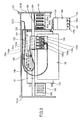
FIG. 4 is a perspective view illustrating an overall configuration of the liquid-jet head 134 according to an embodiment.FIG. 5 is a cross-sectional diagram of the liquid-jet head 134 illustrated inFIG. 4 cut along a line a-a. As illustrated inFIG. 5 , the liquid-jet head 134 according to the embodiment includes apiezoelectric element 5 as an energy application element. Thepiezoelectric element 5 is adhered to abase member 6 such that a drive signal having an optional drive waveform is applied to thepiezoelectric element 5 via electric wiring 7 from not-illustrated electric circuit and control system. Thepiezoelectric element 5 may be displaced or deformed by the drive signal having the drive waveform to apply energy to a recording material inside the pressurizedliquid chamber 11 via a diaphragm plate (diaphragm) 3. Hence, the recording material inside the pressurizedliquid chamber 11 is ejected or discharged via thenozzle 10. The recording material inside the pressurizedliquid chamber 11 is appropriately supplemented from thecommon liquid chamber 12 via the communicatingpath 13 in an amount corresponding to a reduced amount of the recording material. Further, the pressurizedliquid chamber 11 is formed on a Si wafer by anisotropic etching. The pressurizedliquid chamber 11 is etched to a predetermined depth, a part of which has a through hole to communicate with thenozzle 10. The liquid-jet head according to the embodiment is a face-shooter type in which a main deformation direction of thepiezoelectric element 5 matches an ejecting direction of the liquid. The liquid-jet head of this type is becoming a mainstream type of the liquid-jet head. The liquid-jet head of this type has an advantage of easily bonding plate members of the liquid chamber configuration members. - In this embodiment, the
piezoelectric element 5 is diced at 300 dpi intervals, and diced parts of thepiezoelectric element 5 are aligned in two lines to face each other. Thenozzles 10 and the corresponding pressurizedliquid chambers 11 are aligned in a staggered arrangement at 150 dpi per line, and hence a user may be able to acquire resolution of 300 dpi by one scanning. -
FIG. 6 is a view schematically illustrating an ink flow path of the liquid-jet head 134 according to the embodiment.FIG. 6 illustrates a part enclosed by a dotted line taken fromFIG. 5 . The pressurizedliquid chamber 11 includes afluid resistance part 15 having a partial island shape. Thecommon liquid chamber 12 communicates with aconduit 16 to supply ink from an ink reservoir such as a not illustrated ink tank. In this example, theconduit 16 is arranged at an approximate center in a longitudinal direction of thecommon liquid chamber 12. Hence, if the ink flow occurs as a result of a normal printing or maintenance-restoration operations, ink is induced to flow in directions indicated by thick arrows inFIG. 6 . If such ink flow has occurred, foreign particles and air bubbles existing within thecommon liquid chamber 12 travel along the ink flow to reach end regions on two sides of thecommon liquid chamber 12 located downstream in an ink supply direction. As illustrated inFIG. 6 , opening areas corresponding to communicatingpaths 21 arranged at two sides of thecommon liquid chamber 12 are formed such that the opening area of each of the communicatingpaths 21 is larger than an opening area of each of the communicatingpaths 13. Note that the opening area of the communicatingpath 13 is smaller than an opening area of a nozzle 10-1. In this configuration, the communicatingpaths 13 may serve as filters to prevent the foreign particles from intruding into the corresponding pressurizedliquid chambers 11. By contrast, an opening area of the communicatingpath 21 is larger than an opening area of a nozzle 10-2. In this configuration, after the nozzle 10-2 is capped with the cap member of the maintenance-restoration mechanism 181 during the maintenance-restoration operation, foreign particles and air bubbles pass through the openings of the communicatingpaths 21 to be externally discharged from the nozzles 10-2 via the caps to outside the liquid-jet head 134. Accordingly, it may be possible to suppress foreign particles or air bubbles from accumulating inside thecommon liquid chamber 12. Note that the aforementioned foreign particles are smaller than the opening area of the nozzle 10-2 such that the foreign particles may be able to pass through the nozzle 10-2. The nozzle 10-2 may be utilized as so-called dummy bits that serve as bits not utilized for actually forming an image. In the embodiment illustrated inFIG. 6 , the nozzle 10-2 is utilized as the opening to discharge foreign particles or air bubbles received via thecommon liquid chamber 12 and the communicatingpath 21. However, such an opening to discharge foreign particles or air bubbles may be formed in a part of a nozzle surface of the nozzle 10-2 at a position differing from a position of the nozzle surface at which the opening the nozzle 10-2 is formed as illustrated inFIG. 7 . Alternatively, such an opening to discharge foreign particles or air bubbles may be formed, as illustrated inFIG. 8 , in a part of a side wall of a pressurizedliquid chamber 20. -
FIG. 9 is a view schematically illustrating an ink flow path of a first modification of the liquid-jet head 134 according to the embodiment. InFIG. 9 , reference numerals that are identical to those inFIG. 6 indicate components identical to those inFIG. 6 . In this example, the adjacent pressurizedliquid chambers 11 corresponding to five nozzles 10-1 are connected at positions near the communicatingpath 21. In this configuration, the number of openings of the communicatingpaths 13 connecting to the pressurizedliquid chamber 11 may be increased. The example ofFIG. 6 has only five openings as the communicatingpaths 13 corresponding to onepressurized liquid chamber 11. Hence, if some of the five communicating paths are simultaneously clogged with foreign particles or air bubbles, fluid resistance of the communicatingpaths 13 may be increased, which may adversely affect ink discharge properties. Further, if all five communicatingpaths 13 are clogged in the worst scenario, it may be difficult to supply ink via the communicatingpaths 13. However, the aforementioned ink discharge malfunction may be dramatically reduced by connecting the adjacent (five)pressurized liquid chambers 11 to communicate with one another as illustrated inFIG. 9 . In this case, the pressurizedliquid chambers 20 arranged in both end regions one on each end of the pressurizedliquid chamber 12 and the pressurizedliquid chambers 11 adjacent to the respective pressurizedliquid chambers 20 are not in communication with one another. Note that the pressurizedliquid chambers 20 arranged at the two end regions of the pressurizedliquid chamber 12 are utilized as dummy bits so that an opening area of the communicatingpath 21 is formed larger than an opening area of the communicatingpath 13. -
FIGS. 10A and 10B are views schematically illustrating an ink flow path of a second modification of the liquid-jet head 134 according to the embodiment. InFIGS. 10A and 10B , reference numerals that are identical to those inFIG. 6 indicate components identical to those inFIG. 6 . In this example, dummy bits serving as the pressurizedliquid chambers 20 in the two end regions on the two sides of thecommon liquid chamber 12 are determined as two bits, and the fluid resistance part having an island shape is eliminated from the dummy bits. In this configuration, ink may flow easily due to a decrease in fluid resistance of the dummy bits, and relatively large foreign particles and air bubbles may be easily discharged from the liquid-jet head 134. It may be possible to increase the dummy bits; however, the size of the liquid-jet head 134 may be increased with the increase of the dummy bits. Hence, the appropriate number of dummy bits may preferably be increased based on applications. Further, in this example, an outermost side (outermost end) in a longitudinal direction of the opening of the communicatingpath 21 is located outside thecommon liquid chamber 12. This configuration may facilitate causing foreign particles or air bubbles to flow toward the end regions on two sides of thecommon liquid chamber 12 and finally flow into the communicatingpath 21. In the related art, fluid resistance of the end part bits may be reduced by removing the fluid resistance part residing within the dummy bit liquid chamber or by increasing a cross sectional area of the liquid chamber in order to facilitate air bubbles in the end regions on the two sides of the common liquid chamber. However, it may not seem to be sufficient. That is, if small openings such as the communicatingpath 13 illustrated inFIG. 8 are formed in place of the communicatingpath 21 in the end part dummy bits, air bubbles existing inside thecommon liquid chamber 12 may be easily trapped by these small openings. Since smaller air bubbles have particularly high surface tension, a meniscus strained across the small communicating path may not easily be broken by simple pressure application and hence the air bubbles may remain in thecommon liquid chamber 12. Accordingly, the size of the opening of the communicatingpath 21 may need to be increased. -
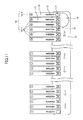
FIG. 11 is a view schematically illustrating ink flow paths of a third modification of the liquid-jet head 134 according to the embodiment. InFIG. 11 , reference numerals that are identical to those inFIG. 6 indicate components identical to those inFIG. 6 . In this example, aconduit 16 communicating with thecommon liquid chamber 12 is formed in an end region on one end of thecommon liquid chamber 12. It may be necessary to arrange theconduit 16 as described above with the limitation of the layout. In this case, an opening area of the communicatingpath 21 according to the third modification is configured to be larger than the opening area of the communicatingpath 21 according to the aforementioned embodiment, the first and the second modifications at a position of an end region opposite to the end region having theconduit 16. Further, the pressurizedliquid chambers 11 may be connected at a position of the communicatingpaths 13, or a bit in an end part located downstream of an ink flow direction in thecommon liquid chamber 12 may be utilized as a dummy bit. - The descriptions of the embodiment and modifications are only examples and the embodiment or modifications of the embodiment may exhibit effects specific to the following aspects.
- A liquid-jet head includes a communicating path configured to communicate with a part of a common liquid chamber including an air bubble remaining part located in a region downstream in a liquid flow direction inside the common liquid chamber, the air bubble remaining part being a place where air bubbles are likely to remain; and an air bubble discharge chamber having an opening to discharge air bubbles having entered via the communicating path, in which an air bubble remaining part having the entered air bubbles are discharged via the opening of the air bubble discharge chamber during maintenance-restoration operations.
- With this configuration, as illustrated in the embodiment, air bubbles may be prevented from intruding into the pressurized
liquid chambers 11 by filters having openings of the communicatingpaths 13 communicating with the corresponding pressurizedliquid chambers 11 and thecommon liquid chamber 12; however, the air bubbles may continue to remain inside thecommon liquid chamber 12 to clog the filters. Further, the liquid-jet head further includes an ink flow path in which the liquid inside thecommon liquid chamber 12 flows via the communicatingpath 21 of the dummy pressurizedliquid chamber 20 to the discharging nozzle 10-2 of the dummy pressurizedliquid chamber 20. Since the dummy pressurizedliquid chamber 20 acquires a negative pressure due to a negative pressure inside thecommon liquid chamber 12 during a time other than the maintenance-restoration operation time, the discharging nozzle 10-2 of the dummy pressurizedliquid chamber 20 does not discharge a liquid. For example, when thecommon liquid chamber 12 has a positive pressure (atmospheric pressure) during the maintenance-restoration operation, the liquid inside thecommon liquid chamber 12 flows via the communicatingpath 21 of the dummy pressurizedliquid chamber 20 to the discharging nozzle 10-2 of the dummy pressurizedliquid chamber 20. With this configuration, even if air bubbles remain in theopenings 13 of the filter on thecommon liquid chamber 12 side, the air bubbles may be discharged outside via the dummy pressurizedliquid chamber 20 during the maintenance-restoration operation. The filters are provided in each of the corresponding pressurizedliquid chambers 11 to prevent air bubbles from intruding into the pressurizedliquid chambers 11. Further, with this configuration, the filters between the corresponding pressurizedliquid chambers 11 and thecommon liquid chamber 12 may not be clogged by the air bubbles or foreign particles so that a sufficient amount of ink may be supplied to the pressurizedliquid chambers 11. Hence, ink discharge malfunction due to the clogging of the filters between the pressurizedliquid chambers 11 and thecommon liquid chamber 12 may be suppressed. - In the configuration of the liquid-jet head according to the above aspect A, the opening of the air bubble discharge chamber is formed in a part of a wall surface of walls constituting the air bubble discharge chamber. With this configuration, as illustrated in the embodiment, the nozzle 10-2 of the dummy pressurized
liquid chamber 20 may be capped with the cap member or the like during the maintenance-restoration operations to discharge air bubbles that continue remaining inside thecommon liquid chamber 12 outside thecommon liquid chamber 12. Thus, the ink discharge malfunction may be suppressed. - In the configuration of the liquid-jet head according to the above aspect B, the opening of the air bubble discharge chamber is formed in a part of a wall surface facing in the same direction as a nozzle surface facing direction. With this configuration, as illustrated in the embodiment, the nozzle 10-2 of the dummy pressurized
liquid chamber 20 may be capped with the cap member or the like during the maintenance-restoration operation to discharge air bubbles that continue to remain inside thecommon liquid chamber 12 from the liquid-jet head 134. Thus, the ink discharge malfunction may be suppressed. - In the configuration of the liquid-jet head according to any one of the above aspects A to C, an opening area of the communicating path in the air bubble discharge chamber is larger than an opening area of the communicating path of the pressurized
liquid chamber 11. With this configuration, as illustrated in the embodiment, the air bubbles that continue to remain inside thecommon liquid chamber 12 may be captured inside the dummy pressurizedliquid chamber 20. Thus, the ink discharge malfunction may be suppressed. - In the configuration of the liquid-jet head according to the above aspect a, two or more air bubble discharge chambers are formed in a region downstream in a liquid flow direction including an air bubble remaining part inside the
common liquid chamber 12. With this configuration, as illustrated in the embodiment, the air bubbles that continue to remain inside thecommon liquid chamber 12 may be efficiently captured inside the dummy pressurizedliquid chamber 20. Thus, the ink discharge malfunction may be suppressed. - In the configuration of the liquid-jet head according to the above aspect E, any two or more of the communicating paths of the air bubble discharge chambers may be connected. With this configuration, as illustrated in the second modification of the embodiment, the opening area of the communicating
path 21 of the dummy pressurizedliquid chamber 20 may be increased and hence, the air bubbles that continue to remain inside thecommon liquid chamber 12 may be efficiently captured inside the dummy pressurizedliquid chamber 20. Thus, the ink discharge malfunction may be suppressed. - In the configuration of the liquid-jet head according to any one of the above aspects A to F, a virtual line extending from a liquid chamber wall downstream of the liquid flow direction inside the common liquid chamber toward the air bubble discharge chamber matches an end part of an outermost inner wall of the communicating path of the air bubble discharge chamber. Or, the virtual line may extend from the liquid chamber wall to an inner part of the communicating path of the air bubble discharge chamber. As illustrated in the embodiment, air bubbles are likely to remain downstream of the common liquid chamber. Hence, with this configuration, the common liquid chamber includes no such air bubble remaining part so as to allow the air bubbles to enter into the communicating path of the air bubble discharge chamber. Thus, the ink discharge malfunction may be suppressed.
- In the configuration of the liquid-jet head according to any one of the above aspects A to G, two or adjacently arranged pressurized
liquid chambers 11 having openings are connected. With this configuration, as illustrated in the first modification of the embodiment, the number of communicatingpaths 13 corresponding to each of the pressurizedliquid chambers 11 may be increased. Accordingly, even if some of the communicating paths are clogged, the liquid may still be supplied to the connected pressurizedliquid chambers 11. Thus, the ink discharge malfunction may be suppressed. - A liquid-jet head includes a communicating path configured to communicate with a part of a common liquid chamber including a foreign particle remaining part located in a region downstream in a liquid flow direction inside the common liquid chamber, the foreign particle remaining part being a place where foreign particles are likely to remain; and a foreign particle discharge chamber having an opening to discharge foreign particles having entered via the communicating path, in which the entered foreign particles are discharged via the opening of the foreign particle discharge chamber during maintenance-restoration operations. With this configuration, as illustrated in the embodiment, foreign particles may be prevented from intruding into the pressurized
liquid chambers 11 by a filter having openings of the communicatingpaths 13 communicating with the corresponding pressurizedliquid chambers 11 and thecommon liquid chamber 12; however, the foreign particles may continue to remain inside thecommon liquid chamber 12 to clog the filter. Hence, the liquid-jet head 134 further includes a foreign particle discharge chamber including a communicatingpath 13 to communicate with thecommon liquid chamber 12 and an opening to externally discharge foreign particles. The foreign particle discharge chamber is arranged in a region downstream of thecommon liquid chamber 12 where foreign particles are likely to remain. The foreign particle discharge chamber serves as a flow path via which remaining foreign particles are externally discharged. Hence, foreign particles are discharged via the foreign particle discharge chamber during the maintenance-restoration operation. With this configuration, the filters will not be clogged so that a sufficient amount of ink may be supplied to the pressurizedliquid chambers 11. Thus, the ink discharge malfunction may be suppressed. - A liquid-jet device includes the liquid-jet head according to any one of the aspects A to I. With this configuration, as illustrated in the embodiment, the liquid-jet device may be capable of stably ejects the liquid. Accordingly, a highly reliable liquid-jet device may be provided.
- According to an embodiment, there is provided a liquid-jet head including a flow path in which a liquid inside a common liquid chamber flows into a discharge opening of an air bubble discharge chamber via a communicating path between the common liquid chamber and an air bubble discharge chamber, and the air bubble discharge chamber. Since a content of the air bubble discharge chamber is in a negative pressure state according to a negative pressure state of a content of the common liquid chamber during a time other than the maintenance-restoration operation time, the liquid will not be discharged from the discharge opening of the air bubble discharge chamber. For example, when the content of the common liquid chamber is in a positive pressure (atmospheric pressure) state during the maintenance-restoration operation, the liquid inside the common liquid chamber flows via the communicating path of the air bubble discharge chamber to the discharge opening of the air bubble discharge chamber. With this configuration, even if air bubbles remain in the filter on the common liquid chamber side, the air bubbles may be discharged outside via the air bubble discharge chamber during the maintenance-restoration operation. The filter is provided in each of the pressurized liquid chambers to prevent air bubbles from intruding into the pressurized liquid chambers. Accordingly, the air bubbles will not continue to remain inside the common liquid chamber and hence, the filters will not be clogged with the air bubbles. Thus, a sufficient amount of the liquid may be supplied to each of the pressurized liquid chambers, which may suppress liquid discharge malfunction due to the clogging of the filters between the corresponding pressurized liquid chambers and the common liquid chamber.
- According to another embodiment, there is provided a liquid-jet head including a flow path in which a liquid inside a common liquid chamber flows into a discharge opening of a foreign particle discharge chamber via a communicating path between the common liquid chamber and a foreign particle discharge chamber, and the foreign particle discharge chamber. Since a content of the foreign particle discharge chamber is in a negative pressure state according to a negative pressure state of a content of the common liquid chamber during a time other than the maintenance-restoration operation time, the liquid will not be discharged from the discharge opening of the foreign particle discharge chamber. For example, when the content of the common liquid chamber is in a positive pressure (atmospheric pressure) state during the maintenance-restoration operation, the liquid inside the common liquid chamber flows via the communicating path of the foreign particle discharge chamber to the discharge opening of the foreign particle discharge chamber. With this configuration, even if foreign particles remain in the filters on the common liquid chamber side, the foreign particles may be discharged outside via the foreign particle discharge chamber during the maintenance-restoration operation. The filters are provided in the corresponding pressurized liquid chambers to prevent foreign particles from intruding into the pressurized liquid chambers. Accordingly, the foreign particles will not continue to remain inside the common liquid chamber and hence, the filters will not be clogged with the foreign particles. Thus, a sufficient amount of the liquid may be supplied to each of the pressurized liquid chambers, which may suppress liquid discharge malfunction due to the clogging of the filters between the corresponding pressurized liquid chambers and the common liquid chamber.
- The embodiments and modifications may be able to provide a distinctive effect for suppressing liquid discharge malfunction due to the clogging of filters between the corresponding pressurized liquid chambers and the common liquid chamber.
- All examples and conditional language recited herein are intended for pedagogical purposes to aid the reader in understanding the principles of the invention and the concepts contributed by the inventor to furthering the art, and are to be construed as being without limitation to such specifically recited examples and conditions, nor does the organization of such examples in the specification relate to a showing of the superiority or inferiority of the invention. Although the embodiment of the present invention has been described in detail, it should be understood that various changes, substitutions, and alterations could be made hereto without departing from the spirit and scope of the invention.
- This patent application is based on Japanese Priority Patent Application No.
2011-202341 filed on September 15, 2011
Claims (10)
- A liquid-jet head comprising:a plurality of nozzles;a plurality of pressurized chambers configured to communicate with the respective nozzles;a common liquid chamber configured to communicate with each of the pressurized chambers, each of the common liquid chamber and the pressurized liquid chambers having a negative pressure of a predetermined value;a plurality of first communicating paths configured to communicate between the common liquid chamber and the corresponding pressurized liquid chamber, the first communicating paths serving as a filter to prevent air bubbles residing in the common liquid chamber from intruding into the corresponding pressurized liquid chamber, the filter having a plurality of openings, each of the openings having an opening area smaller than an opening area of each of the nozzles, the openings serving as a liquid flow path between the common liquid chamber and the corresponding pressurized liquid chamber; andan air bubble discharge chamber including
a second communicating path configured to communicate with the common liquid chamber having an air bubble remaining part where air bubbles are likely to remain, the air bubble remaining part being located in a region downstream in a liquid flow direction inside the common liquid chamber, and
an opening part from which the air bubbles having entered via the second communicating path are discharged, the entered air bubbles being discharged from the opening part during a maintenance-restoration operation. - The liquid-jet head as claimed in claim 1, wherein the opening part of the air bubble discharge chamber is formed in a part of a wall surface of walls constituting the air bubble discharge chamber.
- The liquid-jet head as claimed in claim 2, wherein the opening part of the air bubble discharge chamber is formed in the part of the wall surface facing in a direction same as a direction in which a nozzle surface having the nozzles faces.
- The liquid-jet head as claimed in claim 1, wherein an opening area of the opening part of the second communicating path in the air bubble discharge chamber is larger than an opening area of the first communicating path in the pressurized liquid chamber.
- The liquid-jet head as claimed in claim 1, wherein two or more of the air bubble discharge chambers are formed in a region downstream in a liquid flow direction including the air bubble remaining part inside the common liquid chamber.
- The liquid-jet head as claimed in claim 5, wherein two or more of the second communicating paths of the air bubble discharge chambers are connected with each other.
- The liquid-jet head as claimed in claim 1, wherein
a virtual line extending from a liquid chamber wall located downstream of a liquid flow direction inside the common liquid chamber toward the air bubble discharge chamber matches an end part of an outermost inner wall of the second communicating path of the air bubble discharge chamber, or
the virtual line extends from the liquid chamber wall to an inner part of the second communicating path of the air bubble discharge chamber. - The liquid-jet head as claimed in claim 1, wherein the pressurized liquid chambers that are adjacently arranged are connected to each other.
- A liquid-jet head comprising:a plurality of nozzles;a plurality of pressurized chambers configured to communicate with the respective nozzles;a common liquid chamber configured to communicate with each of the pressurized chambers, each of the common liquid chamber and the pressurized liquid chambers having a negative pressure of a predetermined value;a plurality of first communicating paths configured to communicate between the common liquid chamber and the corresponding pressurized liquid chamber, the first communicating paths serving as a filter to prevent foreign particles residing in the common liquid chamber from intruding into the corresponding pressurized liquid chamber, the filter having a plurality of openings, each of the openings having an opening area smaller than an opening area of each of the nozzles, the openings serving as a liquid flow path between the common liquid chamber and the corresponding pressurized liquid chamber; anda foreign particle discharge chamber including
a second communicating path configured to communicate with the common liquid chamber having a foreign particle remaining part where foreign particles are likely to remain, the foreign particle remaining part being located in a region downstream in a liquid flow direction inside the common liquid chamber, and
an opening part from which the foreign particles having entered via the second communicating path are discharged, the entered foreign particles being discharged from the opening part during a maintenance-restoration operation. - A liquid-jet device comprising the liquid-jet head as claimed in claim 1.
Applications Claiming Priority (1)
| Application Number | Priority Date | Filing Date | Title |
|---|---|---|---|
| JP2011202341A JP5881000B2 (en) | 2011-09-15 | 2011-09-15 | Droplet discharge head and droplet discharge apparatus |
Publications (2)
| Publication Number | Publication Date |
|---|---|
| EP2570263A1 true EP2570263A1 (en) | 2013-03-20 |
| EP2570263B1 EP2570263B1 (en) | 2020-05-27 |
Family
ID=46851306
Family Applications (1)
| Application Number | Title | Priority Date | Filing Date |
|---|---|---|---|
| EP12181547.6A Active EP2570263B1 (en) | 2011-09-15 | 2012-08-23 | Liquid-jet head and liquid-jet head device |
Country Status (4)
| Country | Link |
|---|---|
| US (1) | US8882241B2 (en) |
| EP (1) | EP2570263B1 (en) |
| JP (1) | JP5881000B2 (en) |
| CN (1) | CN102991135A (en) |
Families Citing this family (10)
| Publication number | Priority date | Publication date | Assignee | Title |
|---|---|---|---|---|
| JP6047986B2 (en) | 2012-08-02 | 2016-12-21 | 株式会社リコー | Droplet discharge head, droplet discharge apparatus, and image forming apparatus |
| JP2014076645A (en) | 2012-09-18 | 2014-05-01 | Ricoh Co Ltd | Droplet ejection head, image forming apparatus |
| JP6217217B2 (en) * | 2013-08-01 | 2017-10-25 | セイコーエプソン株式会社 | Liquid discharge head and liquid discharge apparatus |
| JP6319645B2 (en) * | 2013-12-02 | 2018-05-09 | 株式会社リコー | Droplet discharge head and image forming apparatus |
| US9415594B1 (en) * | 2015-07-30 | 2016-08-16 | Xerox Corporation | Single jet having a bubble screen |
| JP6772582B2 (en) * | 2016-06-27 | 2020-10-21 | コニカミノルタ株式会社 | Inkjet head and inkjet recorder |
| KR102614074B1 (en) * | 2016-12-05 | 2023-12-14 | 주식회사 탑 엔지니어링 | Inkjet type liquid dispensing module |
| US10759175B2 (en) | 2018-03-02 | 2020-09-01 | Ricoh Company, Ltd. | Liquid discharge head, head module, liquid discharge device, and liquid discharge apparatus |
| TWI796500B (en) * | 2018-07-30 | 2023-03-21 | 瑞士商西克帕控股有限公司 | A modular service station and a method of servicing an inkjet printhead of an inkjet printing system |
| JP7577550B2 (en) * | 2021-01-25 | 2024-11-05 | 理想テクノロジーズ株式会社 | Liquid ejection head and liquid ejection device |
Citations (5)
| Publication number | Priority date | Publication date | Assignee | Title |
|---|---|---|---|---|
| US5650812A (en) * | 1992-06-09 | 1997-07-22 | Sharp Kabushiki Kaisha | Recording head for preventive air intrusion into the common chamber |
| EP1336487A2 (en) * | 2002-02-15 | 2003-08-20 | Brother Kogyo Kabushiki Kaisha | Ink-jet head |
| US6742883B1 (en) * | 1997-03-28 | 2004-06-01 | Brother Kogyo Kabushiki Kaisha | Ink jet head capable of reliably removing air bubbles from ink |
| JP3885226B2 (en) | 2001-05-31 | 2007-02-21 | ブラザー工業株式会社 | Inkjet head and inkjet recording apparatus |
| JP2011202341A (en) | 2011-06-16 | 2011-10-13 | Mitsubishi Rayon Co Ltd | Method for production of carbon fiber |
Family Cites Families (24)
| Publication number | Priority date | Publication date | Assignee | Title |
|---|---|---|---|---|
| US4639748A (en) * | 1985-09-30 | 1987-01-27 | Xerox Corporation | Ink jet printhead with integral ink filter |
| US5394181A (en) * | 1992-07-29 | 1995-02-28 | Eastman Kodak Company | Air bubble removal in a drop on demand ink jet print head |
| JPH06226966A (en) * | 1993-02-01 | 1994-08-16 | Sharp Corp | Inkjet head |
| JP3235260B2 (en) * | 1993-03-19 | 2001-12-04 | 富士ゼロックス株式会社 | Inkjet head |
| JP2524118Y2 (en) * | 1995-01-09 | 1997-01-29 | セイコーエプソン株式会社 | Inkjet recording head |
| JPH0948116A (en) | 1995-08-07 | 1997-02-18 | Sony Corp | Printer device |
| JPH11221918A (en) | 1998-02-05 | 1999-08-17 | Nec Niigata Ltd | Ink-jet recording head |
| JP3818010B2 (en) * | 2000-04-04 | 2006-09-06 | コニカミノルタホールディングス株式会社 | Inkjet head |
| US6685299B2 (en) | 2001-05-31 | 2004-02-03 | Brother Kogyo Kabushiki Kaisha | Ink jet head |
| US7101030B2 (en) * | 2003-05-21 | 2006-09-05 | Xerox Corporation | Formation of novel ink jet filter printhead using transferable photopatterned filter layer |
| JP2005246656A (en) | 2004-03-02 | 2005-09-15 | Ricoh Co Ltd | Droplet discharge head, liquid discharge apparatus, and image forming apparatus |
| JP2005262639A (en) | 2004-03-18 | 2005-09-29 | Ricoh Printing Systems Ltd | Inkjet printing head cleaning apparatus |
| JP4602786B2 (en) | 2005-02-09 | 2010-12-22 | 株式会社リコー | Image forming apparatus |
| JP4983001B2 (en) * | 2005-11-04 | 2012-07-25 | ブラザー工業株式会社 | Inkjet head |
| US8197048B2 (en) | 2006-04-26 | 2012-06-12 | Ricoh Company, Ltd. | Image forming apparatus |
| US8042911B2 (en) | 2006-11-10 | 2011-10-25 | Ricoh Company, Ltd. | Liquid dispenser head, liquid dispensing unit using same, and image forming apparatus using same |
| JP4869108B2 (en) * | 2007-03-01 | 2012-02-08 | 株式会社リコー | Liquid ejection head, liquid cartridge, and image forming apparatus |
| JP5169041B2 (en) | 2007-07-03 | 2013-03-27 | 株式会社リコー | Liquid ejection head unit and image forming apparatus |
| JP2009066890A (en) * | 2007-09-13 | 2009-04-02 | Ricoh Co Ltd | Liquid ejection head and image forming apparatus |
| JP2009066904A (en) | 2007-09-13 | 2009-04-02 | Ricoh Co Ltd | Liquid ejection head and image forming apparatus |
| JP5294884B2 (en) * | 2008-02-08 | 2013-09-18 | キヤノン株式会社 | Liquid discharge head |
| JP5354719B2 (en) * | 2008-12-08 | 2013-11-27 | エスアイアイ・プリンテック株式会社 | Liquid jet head chip, liquid jet head, and liquid jet recording apparatus |
| JP5375669B2 (en) | 2009-06-29 | 2013-12-25 | 株式会社リコー | Liquid ejection head, liquid droplet ejection apparatus, and image forming apparatus |
| JP5824928B2 (en) | 2010-09-16 | 2015-12-02 | 株式会社リコー | Image forming apparatus and program |
-
2011
- 2011-09-15 JP JP2011202341A patent/JP5881000B2/en active Active
-
2012
- 2012-08-23 EP EP12181547.6A patent/EP2570263B1/en active Active
- 2012-09-10 US US13/609,125 patent/US8882241B2/en active Active
- 2012-09-17 CN CN2012104420652A patent/CN102991135A/en active Pending
Patent Citations (5)
| Publication number | Priority date | Publication date | Assignee | Title |
|---|---|---|---|---|
| US5650812A (en) * | 1992-06-09 | 1997-07-22 | Sharp Kabushiki Kaisha | Recording head for preventive air intrusion into the common chamber |
| US6742883B1 (en) * | 1997-03-28 | 2004-06-01 | Brother Kogyo Kabushiki Kaisha | Ink jet head capable of reliably removing air bubbles from ink |
| JP3885226B2 (en) | 2001-05-31 | 2007-02-21 | ブラザー工業株式会社 | Inkjet head and inkjet recording apparatus |
| EP1336487A2 (en) * | 2002-02-15 | 2003-08-20 | Brother Kogyo Kabushiki Kaisha | Ink-jet head |
| JP2011202341A (en) | 2011-06-16 | 2011-10-13 | Mitsubishi Rayon Co Ltd | Method for production of carbon fiber |
Also Published As
| Publication number | Publication date |
|---|---|
| JP5881000B2 (en) | 2016-03-09 |
| US8882241B2 (en) | 2014-11-11 |
| EP2570263B1 (en) | 2020-05-27 |
| US20130070018A1 (en) | 2013-03-21 |
| JP2013063532A (en) | 2013-04-11 |
| CN102991135A (en) | 2013-03-27 |
Similar Documents
| Publication | Publication Date | Title |
|---|---|---|
| US8882241B2 (en) | Liquid-jet head and liquid-jet head device | |
| US9427968B2 (en) | Liquid discharge head and image forming apparatus | |
| US8888260B2 (en) | Liquid-jet head and image forming apparatus | |
| US20100194823A1 (en) | Liquid ejection head, ink cartridge, and image forming apparatus | |
| JP4841349B2 (en) | Liquid ejection head unit and image forming apparatus | |
| US20130307911A1 (en) | Liquid discharge head and image forming apparatus | |
| US8052248B2 (en) | Liquid ejection head and image forming apparatus | |
| US9120320B2 (en) | Liquid ejection head and image forming device | |
| JP2010099880A (en) | Liquid discharge head and image forming apparatus | |
| JP5504916B2 (en) | Droplet discharge apparatus and image forming apparatus | |
| JP5720979B2 (en) | Recovery device and image forming apparatus | |
| JP2010000671A (en) | Ink cartridge and image forming device | |
| JP5043610B2 (en) | Image forming apparatus | |
| US8727494B2 (en) | Droplet ejection device and image forming apparatus | |
| JP2009262492A (en) | Image forming apparatus | |
| JP2019098593A (en) | Liquid discharge head protection member, liquid discharge head, and liquid discharge unit | |
| JP2012250484A (en) | Liquid droplet ejection head, and image forming apparatus | |
| JP5471459B2 (en) | Liquid ejection head and image forming apparatus | |
| JP5065845B2 (en) | Liquid ejection head, liquid ejection apparatus, and image forming apparatus | |
| JP2004106433A (en) | Inkjet recording device | |
| JP5434678B2 (en) | Image forming apparatus | |
| JP4688189B2 (en) | Liquid supply apparatus and image forming apparatus | |
| JP5365036B2 (en) | Liquid ejection head and image forming apparatus | |
| JP2013059942A (en) | Liquid droplet ejection head, manufacturing method thereof, cartridge integrated with liquid droplet ejection head, and image forming apparatus | |
| JP2009056743A (en) | Liquid ejection head and image forming apparatus |
Legal Events
| Date | Code | Title | Description |
|---|---|---|---|
| PUAI | Public reference made under article 153(3) epc to a published international application that has entered the european phase |
Free format text: ORIGINAL CODE: 0009012 |
|
| 17P | Request for examination filed |
Effective date: 20120823 |
|
| AK | Designated contracting states |
Kind code of ref document: A1 Designated state(s): AL AT BE BG CH CY CZ DE DK EE ES FI FR GB GR HR HU IE IS IT LI LT LU LV MC MK MT NL NO PL PT RO RS SE SI SK SM TR |
|
| AX | Request for extension of the european patent |
Extension state: BA ME |
|
| 17Q | First examination report despatched |
Effective date: 20140226 |
|
| STAA | Information on the status of an ep patent application or granted ep patent |
Free format text: STATUS: EXAMINATION IS IN PROGRESS |
|
| GRAP | Despatch of communication of intention to grant a patent |
Free format text: ORIGINAL CODE: EPIDOSNIGR1 |
|
| STAA | Information on the status of an ep patent application or granted ep patent |
Free format text: STATUS: GRANT OF PATENT IS INTENDED |
|
| INTG | Intention to grant announced |
Effective date: 20200115 |
|
| RIN1 | Information on inventor provided before grant (corrected) |
Inventor name: SASAKI, TAKAFUMI |
|
| GRAS | Grant fee paid |
Free format text: ORIGINAL CODE: EPIDOSNIGR3 |
|
| GRAA | (expected) grant |
Free format text: ORIGINAL CODE: 0009210 |
|
| STAA | Information on the status of an ep patent application or granted ep patent |
Free format text: STATUS: THE PATENT HAS BEEN GRANTED |
|
| AK | Designated contracting states |
Kind code of ref document: B1 Designated state(s): AL AT BE BG CH CY CZ DE DK EE ES FI FR GB GR HR HU IE IS IT LI LT LU LV MC MK MT NL NO PL PT RO RS SE SI SK SM TR |
|
| REG | Reference to a national code |
Ref country code: GB Ref legal event code: FG4D |
|
| REG | Reference to a national code |
Ref country code: CH Ref legal event code: EP |
|
| REG | Reference to a national code |
Ref country code: AT Ref legal event code: REF Ref document number: 1274166 Country of ref document: AT Kind code of ref document: T Effective date: 20200615 |
|
| REG | Reference to a national code |
Ref country code: DE Ref legal event code: R096 Ref document number: 602012070310 Country of ref document: DE |
|
| REG | Reference to a national code |
Ref country code: DE Ref legal event code: R081 Ref document number: 602012070310 Country of ref document: DE Owner name: RICOH COMPANY, LTD., JP Free format text: FORMER OWNER: RICOH COMPANY LTD., TOKYO, JP |
|
| REG | Reference to a national code |
Ref country code: NL Ref legal event code: FP |
|
| REG | Reference to a national code |
Ref country code: LT Ref legal event code: MG4D |
|
| PG25 | Lapsed in a contracting state [announced via postgrant information from national office to epo] |
Ref country code: PT Free format text: LAPSE BECAUSE OF FAILURE TO SUBMIT A TRANSLATION OF THE DESCRIPTION OR TO PAY THE FEE WITHIN THE PRESCRIBED TIME-LIMIT Effective date: 20200928 Ref country code: GR Free format text: LAPSE BECAUSE OF FAILURE TO SUBMIT A TRANSLATION OF THE DESCRIPTION OR TO PAY THE FEE WITHIN THE PRESCRIBED TIME-LIMIT Effective date: 20200828 Ref country code: NO Free format text: LAPSE BECAUSE OF FAILURE TO SUBMIT A TRANSLATION OF THE DESCRIPTION OR TO PAY THE FEE WITHIN THE PRESCRIBED TIME-LIMIT Effective date: 20200827 Ref country code: IS Free format text: LAPSE BECAUSE OF FAILURE TO SUBMIT A TRANSLATION OF THE DESCRIPTION OR TO PAY THE FEE WITHIN THE PRESCRIBED TIME-LIMIT Effective date: 20200927 Ref country code: SE Free format text: LAPSE BECAUSE OF FAILURE TO SUBMIT A TRANSLATION OF THE DESCRIPTION OR TO PAY THE FEE WITHIN THE PRESCRIBED TIME-LIMIT Effective date: 20200527 Ref country code: FI Free format text: LAPSE BECAUSE OF FAILURE TO SUBMIT A TRANSLATION OF THE DESCRIPTION OR TO PAY THE FEE WITHIN THE PRESCRIBED TIME-LIMIT Effective date: 20200527 Ref country code: LT Free format text: LAPSE BECAUSE OF FAILURE TO SUBMIT A TRANSLATION OF THE DESCRIPTION OR TO PAY THE FEE WITHIN THE PRESCRIBED TIME-LIMIT Effective date: 20200527 |
|
| PG25 | Lapsed in a contracting state [announced via postgrant information from national office to epo] |
Ref country code: BG Free format text: LAPSE BECAUSE OF FAILURE TO SUBMIT A TRANSLATION OF THE DESCRIPTION OR TO PAY THE FEE WITHIN THE PRESCRIBED TIME-LIMIT Effective date: 20200827 Ref country code: LV Free format text: LAPSE BECAUSE OF FAILURE TO SUBMIT A TRANSLATION OF THE DESCRIPTION OR TO PAY THE FEE WITHIN THE PRESCRIBED TIME-LIMIT Effective date: 20200527 Ref country code: RS Free format text: LAPSE BECAUSE OF FAILURE TO SUBMIT A TRANSLATION OF THE DESCRIPTION OR TO PAY THE FEE WITHIN THE PRESCRIBED TIME-LIMIT Effective date: 20200527 Ref country code: HR Free format text: LAPSE BECAUSE OF FAILURE TO SUBMIT A TRANSLATION OF THE DESCRIPTION OR TO PAY THE FEE WITHIN THE PRESCRIBED TIME-LIMIT Effective date: 20200527 |
|
| REG | Reference to a national code |
Ref country code: AT Ref legal event code: MK05 Ref document number: 1274166 Country of ref document: AT Kind code of ref document: T Effective date: 20200527 |
|
| PG25 | Lapsed in a contracting state [announced via postgrant information from national office to epo] |
Ref country code: AL Free format text: LAPSE BECAUSE OF FAILURE TO SUBMIT A TRANSLATION OF THE DESCRIPTION OR TO PAY THE FEE WITHIN THE PRESCRIBED TIME-LIMIT Effective date: 20200527 |
|
| PG25 | Lapsed in a contracting state [announced via postgrant information from national office to epo] |
Ref country code: RO Free format text: LAPSE BECAUSE OF FAILURE TO SUBMIT A TRANSLATION OF THE DESCRIPTION OR TO PAY THE FEE WITHIN THE PRESCRIBED TIME-LIMIT Effective date: 20200527 Ref country code: AT Free format text: LAPSE BECAUSE OF FAILURE TO SUBMIT A TRANSLATION OF THE DESCRIPTION OR TO PAY THE FEE WITHIN THE PRESCRIBED TIME-LIMIT Effective date: 20200527 Ref country code: IT Free format text: LAPSE BECAUSE OF FAILURE TO SUBMIT A TRANSLATION OF THE DESCRIPTION OR TO PAY THE FEE WITHIN THE PRESCRIBED TIME-LIMIT Effective date: 20200527 Ref country code: DK Free format text: LAPSE BECAUSE OF FAILURE TO SUBMIT A TRANSLATION OF THE DESCRIPTION OR TO PAY THE FEE WITHIN THE PRESCRIBED TIME-LIMIT Effective date: 20200527 Ref country code: EE Free format text: LAPSE BECAUSE OF FAILURE TO SUBMIT A TRANSLATION OF THE DESCRIPTION OR TO PAY THE FEE WITHIN THE PRESCRIBED TIME-LIMIT Effective date: 20200527 Ref country code: SM Free format text: LAPSE BECAUSE OF FAILURE TO SUBMIT A TRANSLATION OF THE DESCRIPTION OR TO PAY THE FEE WITHIN THE PRESCRIBED TIME-LIMIT Effective date: 20200527 Ref country code: ES Free format text: LAPSE BECAUSE OF FAILURE TO SUBMIT A TRANSLATION OF THE DESCRIPTION OR TO PAY THE FEE WITHIN THE PRESCRIBED TIME-LIMIT Effective date: 20200527 Ref country code: CZ Free format text: LAPSE BECAUSE OF FAILURE TO SUBMIT A TRANSLATION OF THE DESCRIPTION OR TO PAY THE FEE WITHIN THE PRESCRIBED TIME-LIMIT Effective date: 20200527 |
|
| PG25 | Lapsed in a contracting state [announced via postgrant information from national office to epo] |
Ref country code: SK Free format text: LAPSE BECAUSE OF FAILURE TO SUBMIT A TRANSLATION OF THE DESCRIPTION OR TO PAY THE FEE WITHIN THE PRESCRIBED TIME-LIMIT Effective date: 20200527 Ref country code: PL Free format text: LAPSE BECAUSE OF FAILURE TO SUBMIT A TRANSLATION OF THE DESCRIPTION OR TO PAY THE FEE WITHIN THE PRESCRIBED TIME-LIMIT Effective date: 20200527 |
|
| REG | Reference to a national code |
Ref country code: DE Ref legal event code: R097 Ref document number: 602012070310 Country of ref document: DE |
|
| PG25 | Lapsed in a contracting state [announced via postgrant information from national office to epo] |
Ref country code: MC Free format text: LAPSE BECAUSE OF FAILURE TO SUBMIT A TRANSLATION OF THE DESCRIPTION OR TO PAY THE FEE WITHIN THE PRESCRIBED TIME-LIMIT Effective date: 20200527 |
|
| REG | Reference to a national code |
Ref country code: CH Ref legal event code: PL |
|
| PLBE | No opposition filed within time limit |
Free format text: ORIGINAL CODE: 0009261 |
|
| STAA | Information on the status of an ep patent application or granted ep patent |
Free format text: STATUS: NO OPPOSITION FILED WITHIN TIME LIMIT |
|
| PG25 | Lapsed in a contracting state [announced via postgrant information from national office to epo] |
Ref country code: LU Free format text: LAPSE BECAUSE OF NON-PAYMENT OF DUE FEES Effective date: 20200823 Ref country code: LI Free format text: LAPSE BECAUSE OF NON-PAYMENT OF DUE FEES Effective date: 20200831 Ref country code: CH Free format text: LAPSE BECAUSE OF NON-PAYMENT OF DUE FEES Effective date: 20200831 |
|
| 26N | No opposition filed |
Effective date: 20210302 |
|
| REG | Reference to a national code |
Ref country code: BE Ref legal event code: MM Effective date: 20200831 |
|
| PG25 | Lapsed in a contracting state [announced via postgrant information from national office to epo] |
Ref country code: SI Free format text: LAPSE BECAUSE OF FAILURE TO SUBMIT A TRANSLATION OF THE DESCRIPTION OR TO PAY THE FEE WITHIN THE PRESCRIBED TIME-LIMIT Effective date: 20200527 |
|
| PG25 | Lapsed in a contracting state [announced via postgrant information from national office to epo] |
Ref country code: IE Free format text: LAPSE BECAUSE OF NON-PAYMENT OF DUE FEES Effective date: 20200823 Ref country code: BE Free format text: LAPSE BECAUSE OF NON-PAYMENT OF DUE FEES Effective date: 20200831 |
|
| PG25 | Lapsed in a contracting state [announced via postgrant information from national office to epo] |
Ref country code: TR Free format text: LAPSE BECAUSE OF FAILURE TO SUBMIT A TRANSLATION OF THE DESCRIPTION OR TO PAY THE FEE WITHIN THE PRESCRIBED TIME-LIMIT Effective date: 20200527 Ref country code: MT Free format text: LAPSE BECAUSE OF FAILURE TO SUBMIT A TRANSLATION OF THE DESCRIPTION OR TO PAY THE FEE WITHIN THE PRESCRIBED TIME-LIMIT Effective date: 20200527 Ref country code: CY Free format text: LAPSE BECAUSE OF FAILURE TO SUBMIT A TRANSLATION OF THE DESCRIPTION OR TO PAY THE FEE WITHIN THE PRESCRIBED TIME-LIMIT Effective date: 20200527 |
|
| PG25 | Lapsed in a contracting state [announced via postgrant information from national office to epo] |
Ref country code: MK Free format text: LAPSE BECAUSE OF FAILURE TO SUBMIT A TRANSLATION OF THE DESCRIPTION OR TO PAY THE FEE WITHIN THE PRESCRIBED TIME-LIMIT Effective date: 20200527 |
|
| P01 | Opt-out of the competence of the unified patent court (upc) registered |
Effective date: 20230522 |
|
| PGFP | Annual fee paid to national office [announced via postgrant information from national office to epo] |
Ref country code: NL Payment date: 20250821 Year of fee payment: 14 |
|
| PGFP | Annual fee paid to national office [announced via postgrant information from national office to epo] |
Ref country code: DE Payment date: 20250820 Year of fee payment: 14 |
|
| PGFP | Annual fee paid to national office [announced via postgrant information from national office to epo] |
Ref country code: GB Payment date: 20250821 Year of fee payment: 14 |
|
| PGFP | Annual fee paid to national office [announced via postgrant information from national office to epo] |
Ref country code: FR Payment date: 20250829 Year of fee payment: 14 |