EP2570217B1 - Procédé d'écroutage semi-complet et dispositif doté d'un outil d'écroutage associé pour développer un procédé d'écroutage semi-complet - Google Patents
Procédé d'écroutage semi-complet et dispositif doté d'un outil d'écroutage associé pour développer un procédé d'écroutage semi-complet Download PDFInfo
- Publication number
- EP2570217B1 EP2570217B1 EP11181521.3A EP11181521A EP2570217B1 EP 2570217 B1 EP2570217 B1 EP 2570217B1 EP 11181521 A EP11181521 A EP 11181521A EP 2570217 B1 EP2570217 B1 EP 2570217B1
- Authority
- EP
- European Patent Office
- Prior art keywords
- workpiece
- skiving
- tool
- machining
- cutting
- Prior art date
- Legal status (The legal status is an assumption and is not a legal conclusion. Google has not performed a legal analysis and makes no representation as to the accuracy of the status listed.)
- Active
Links
Images


Classifications
-
- B—PERFORMING OPERATIONS; TRANSPORTING
- B23—MACHINE TOOLS; METAL-WORKING NOT OTHERWISE PROVIDED FOR
- B23F—MAKING GEARS OR TOOTHED RACKS
- B23F5/00—Making straight gear teeth involving moving a tool relatively to a workpiece with a rolling-off or an enveloping motion with respect to the gear teeth to be made
- B23F5/12—Making straight gear teeth involving moving a tool relatively to a workpiece with a rolling-off or an enveloping motion with respect to the gear teeth to be made by planing or slotting
- B23F5/16—Making straight gear teeth involving moving a tool relatively to a workpiece with a rolling-off or an enveloping motion with respect to the gear teeth to be made by planing or slotting the tool having a shape similar to that of a spur wheel or part thereof
- B23F5/163—Making straight gear teeth involving moving a tool relatively to a workpiece with a rolling-off or an enveloping motion with respect to the gear teeth to be made by planing or slotting the tool having a shape similar to that of a spur wheel or part thereof the tool and workpiece being in crossed axis arrangement, e.g. skiving, i.e. "Waelzschaelen"
-
- B—PERFORMING OPERATIONS; TRANSPORTING
- B23—MACHINE TOOLS; METAL-WORKING NOT OTHERWISE PROVIDED FOR
- B23F—MAKING GEARS OR TOOTHED RACKS
- B23F1/00—Making gear teeth by tools of which the profile matches the profile of the required surface
- B23F1/04—Making gear teeth by tools of which the profile matches the profile of the required surface by planing or slotting
-
- B—PERFORMING OPERATIONS; TRANSPORTING
- B23—MACHINE TOOLS; METAL-WORKING NOT OTHERWISE PROVIDED FOR
- B23F—MAKING GEARS OR TOOTHED RACKS
- B23F1/00—Making gear teeth by tools of which the profile matches the profile of the required surface
- B23F1/06—Making gear teeth by tools of which the profile matches the profile of the required surface by milling
-
- B—PERFORMING OPERATIONS; TRANSPORTING
- B23—MACHINE TOOLS; METAL-WORKING NOT OTHERWISE PROVIDED FOR
- B23F—MAKING GEARS OR TOOTHED RACKS
- B23F23/00—Accessories or equipment combined with or arranged in, or specially designed to form part of, gear-cutting machines
- B23F23/12—Other devices, e.g. tool holders; Checking devices for controlling workpieces in machines for manufacturing gear teeth
-
- B—PERFORMING OPERATIONS; TRANSPORTING
- B23—MACHINE TOOLS; METAL-WORKING NOT OTHERWISE PROVIDED FOR
- B23F—MAKING GEARS OR TOOTHED RACKS
- B23F17/00—Special methods or machines for making gear teeth, not covered by the preceding groups
- B23F17/006—Special methods or machines for making gear teeth, not covered by the preceding groups using different machines or machining operations
-
- Y—GENERAL TAGGING OF NEW TECHNOLOGICAL DEVELOPMENTS; GENERAL TAGGING OF CROSS-SECTIONAL TECHNOLOGIES SPANNING OVER SEVERAL SECTIONS OF THE IPC; TECHNICAL SUBJECTS COVERED BY FORMER USPC CROSS-REFERENCE ART COLLECTIONS [XRACs] AND DIGESTS
- Y10—TECHNICAL SUBJECTS COVERED BY FORMER USPC
- Y10T—TECHNICAL SUBJECTS COVERED BY FORMER US CLASSIFICATION
- Y10T409/00—Gear cutting, milling, or planing
- Y10T409/10—Gear cutting
- Y10T409/101431—Gear tooth shape generating
- Y10T409/103816—Milling with radial faced tool
- Y10T409/103975—Process
-
- Y—GENERAL TAGGING OF NEW TECHNOLOGICAL DEVELOPMENTS; GENERAL TAGGING OF CROSS-SECTIONAL TECHNOLOGIES SPANNING OVER SEVERAL SECTIONS OF THE IPC; TECHNICAL SUBJECTS COVERED BY FORMER USPC CROSS-REFERENCE ART COLLECTIONS [XRACs] AND DIGESTS
- Y10—TECHNICAL SUBJECTS COVERED BY FORMER USPC
- Y10T—TECHNICAL SUBJECTS COVERED BY FORMER US CLASSIFICATION
- Y10T409/00—Gear cutting, milling, or planing
- Y10T409/10—Gear cutting
- Y10T409/101431—Gear tooth shape generating
- Y10T409/10477—Gear tooth shape generating by relative axial movement between synchronously indexing or rotating work and cutter
- Y10T409/105088—Displacing cutter axially relative to work [e.g., gear shaving, etc.]
-
- Y—GENERAL TAGGING OF NEW TECHNOLOGICAL DEVELOPMENTS; GENERAL TAGGING OF CROSS-SECTIONAL TECHNOLOGIES SPANNING OVER SEVERAL SECTIONS OF THE IPC; TECHNICAL SUBJECTS COVERED BY FORMER USPC CROSS-REFERENCE ART COLLECTIONS [XRACs] AND DIGESTS
- Y10—TECHNICAL SUBJECTS COVERED BY FORMER USPC
- Y10T—TECHNICAL SUBJECTS COVERED BY FORMER US CLASSIFICATION
- Y10T409/00—Gear cutting, milling, or planing
- Y10T409/10—Gear cutting
- Y10T409/101431—Gear tooth shape generating
- Y10T409/105724—Gear shaving
-
- Y—GENERAL TAGGING OF NEW TECHNOLOGICAL DEVELOPMENTS; GENERAL TAGGING OF CROSS-SECTIONAL TECHNOLOGIES SPANNING OVER SEVERAL SECTIONS OF THE IPC; TECHNICAL SUBJECTS COVERED BY FORMER USPC CROSS-REFERENCE ART COLLECTIONS [XRACs] AND DIGESTS
- Y10—TECHNICAL SUBJECTS COVERED BY FORMER USPC
- Y10T—TECHNICAL SUBJECTS COVERED BY FORMER US CLASSIFICATION
- Y10T409/00—Gear cutting, milling, or planing
- Y10T409/10—Gear cutting
- Y10T409/107791—Using rotary cutter
- Y10T409/10795—Process
Definitions
- the invention relates to a method for semi-completing skiving a toothing or other periodic structure and a device with a corresponding skiving tool for performing a semi-completing WälzWarl Kunststoffs.
- a tool with corresponding knives is used to cut the flanks of a workpiece.
- the workpiece is continuously operated in a single clamping, i. cut in the non-stop process.
- the continuous process is based on complex, coupled motion sequences in which the tool and the workpiece to be machined perform a continuous pitch movement relative to each other.
- the pitch movement results from the coordinated, respectively coupled driving multiple axle drives of a corresponding machine.
- a tooth gap is machined, then, for example, a relative movement of the tool and a so-called pitching (pitch rotation), in which the workpiece rotates relative to the tool, before then the next tooth gap is processed. It is thus produced step by step a gear.
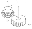
- the Wälzstoss snake mentioned above can be described or represented by a Zylinderradgetriebe because the crossing angle (also called Achsnchwinkel) between the rotation axis R1 of the impact tool 1 and the rotation axis R2 of the workpiece 2 is zero degrees, as in Fig. 1 shown schematically.
- the two rotation axes R1 and R2 are parallel when the axis cross angle is zero degrees.
- the workpiece 2 and the impact tool 1 rotate continuously about their axes of rotation R2, or R1.
- the impact tool 1 makes in addition to the rotational movement a lifting movement in Fig. 1 is designated by the double arrow s hx , and decreases in this stroke movement chips from the workpiece 2.
- skiving was revisited.
- the basics are about 100 years old.
- a first patent application with the number DE 243514 on this topic goes to the year 1912 back. After the original considerations and investigations of the early years, the skiving was no longer pursued seriously.
- complex processes, some of which were empirical, were necessary to find a suitable tool geometry for the skiving process.
- the resulting relative movement between the skiving tool 10 and the workpiece 20 is a screwing movement, which can be decomposed into a rotational component (rotational component) and a thrust component (translational component).
- a Wälzschraubgetriebe can be considered, the rotational component of the rolling and the thrust component corresponds to the sliding of the flanks.
- the sliding portion of the meshing relative movement of the meshing gears of the jackboltset gear is utilized to perform the cutting movement.
- the cutting speed during skiving is influenced directly by the rotational speed of the skiving tool 10 or of the workpiece 20 and of the used axis cross angle ⁇ of the axes of rotation R1 and R2.
- the axis cross angle ⁇ and thus the sliding part should be selected so that an optimal cutting speed is achieved for the machining of the material at a given speed.
- Fig. 2A shows the WälzWarlen external teeth on a cylindrical workpiece 20.
- the workpiece 20 and the tool 10 (here a cylindrical WälzWarltechnikmaschine 10) rotate in the opposite direction, as in Fig. 2A can be seen, for example, based on the angular velocities ⁇ 1 and ⁇ 2 .
- the differential feed s D and the axial feed s ax are coordinated at the design point such that the resulting feed of the tool 10 relative to the workpiece 20 in the direction of the tooth gap to be generated.
- a radial feed s rad can be used to affect about the crown of the toothing of the workpiece 20.
- the vector of the cutting speed results v c essentially as a difference between the two velocity vectors which are inclined relative to each other by the axis crossing angle ⁇ v 1 and v 2 of the rotation axes R1, R2 of tool 10 and workpiece 20th
- v 1 is the velocity vector at the periphery of the tool 10
- v 2 is the velocity vector around the circumference of the workpiece 20.
- the cutting speed v c of the WälzWarlvones can be changed by the Achsnchwinkel ⁇ and the speed in fferradersatzgetriebe.
- the relatively slow axial feed s ax has only a small influence on the cutting speed v c in the skiving method, which can be neglected. Therefore, the axial feed s ax is in the vector diagram with the vectors v 1 , v 2 and v c in Fig. 2A not considered.
- Fig. 2B 2 shows the skiving of external teeth of a workpiece 20 with a conical skiving tool 10.
- Fig. 2B are again the axis cross angle ⁇ , the vector of the cutting speed v c , the velocity vectors v 1 on the circumference of the tool 10 and v 2 on the circumference of the workpiece 20, as well as the helix angle ß 1 of the tool 10 and the helix angle ß 2 of the workpiece 20 shown.
- the helix angle ⁇ 2 is not equal to zero here.
- the tooth tip of the tool 10 is in Fig. 2B denoted by the reference numeral 4.
- the tooth face is in Fig. 2B marked with the reference numeral 5.
- the two axes of rotation R1 and R2 do not intersect, but are skewed to each other.
- the design point AP is usually selected on the common lot of the two rotation axes R1 and R2, since tilting of the skiving tool 10 is not necessary for obtaining clearance angles.
- the design point AP coincides here with the so-called touch point BP.
- the rolling circles of the ffercialzersatzgetriebes touch In this design point AP, the rolling circles of the erklalzersatzgetriebes touch.
- flank cutting / flank cutting are in Fig. 2A and Fig. 2B Not shown.
- the shape and arrangement of the flank cutters are among those aspects that need to be considered in practice in a specific design.
- the skiving tool 10 has in the in Fig. 2A shown example the shape of a spur gear spur gear.
- the outer contour of the main body in Fig. 2A is cylindrical. But it can also be conical (also called conical), as in Fig. 2B shown. Since the tooth or teeth of the skiving tool 10 engage over the entire length of the flank cutting edge, each tooth of the tool 10 on the flank cutting requires a sufficient clearance angle.
- a semi-completing method is an approach in which in a first cut both right and left flanks of tooth gaps are processed, but only the geometries of the right or left flanks are finished. Then, in a second cut, after the machine setting has been changed, one of the two flanks is reworked to obtain the desired gap width and tooth geometry.
- One reason for applying a semi-completing method is seen in that the flanks can be made more free. That so-called flank modifications are easier to do than with the completing procedure.
- the tooth thickness can be corrected in semi-completing by changing the gap width by simply turning the wheel.
- the semi-completing procedure is known for bevel gears originally from grinding in the itemized process of gears pre-milled in the Zyklo-Palloid® process.
- Object of the present invention is to provide a method and apparatus for machining the tooth flanks of a gear or provide other periodic structures, which is characterized by a reduction in production costs per gear or workpiece.
- This object is achieved according to the present invention by a method which is referred to herein as an alternating semi-completing skiving method. That is, the object is achieved according to the present invention by a method based on the principle of the semi-completing method.
- an alternating approach is implemented.
- Characteristic of the method of the invention is that when manufacturing, for example, a toothing, the two flanks with different settings, but with the same tool continuously rolling using an alternating semi-completing approach. It is in the nature of the semi-completing approach that e.g. All left flank cutting of the tool will be used twice, while the right flank cutting will only be used once. Therefore, according to the invention for producing a toothing the same tool is used so that the edge cutting, which were previously exposed to a stronger and / or longer processing time (in the example, the left flank cutting) in subsequent steps now less or frequently used. This is achieved by the fact that the other flank cutting edges (in the example mentioned, the right flank cutting edges) are used more frequently or more frequently during the production of the second toothing.
- One can according to the invention in addition to the wear of the edge cutting also compensate for the wear on the head cutting or evenly distributed.
- the alternating semi-completing skiving method can be used in connection with the production of rotationally symmetric, periodic, structures such as gears and the like.
- a tool is used, which is referred to here as a skiving tool.
- the third and fourth processing phase does not necessarily follow immediately after the first and second processing phase. It is also possible, for example, to subject a plurality of workpieces to a first and second processing phase and then to subsequently subject other workpieces to the third and fourth processing phases. Overall, however, it should be ensured that the alternating in the semi-completing processing in about an equal distribution of the load of the right flank cutting and left flank cutting of WälzWarltechnikmaschines is achieved.
- the rotationally symmetric, periodic structures of the workpieces need not necessarily have symmetrical teeth, or symmetrical tooth spaces, grooves or grooves.
- workpieces with symmetrical teeth are shown and described for the sake of simplicity.
- the invention can also be applied to asymmetric structures.
- the first and second relative positions and the third and fourth relative positions differ from each other.
- the first relative position preferably corresponds to the fourth relative position and the second relative position to the third relative position.
- the head cutting edge on the skiving tool has a width which is smaller than the gap width at the tooth root of the (tooth) gaps to be machined on the first workpiece and on the second workpiece.
- the wear of the head cutting can be evenly distributed by the width of the head cutting is selected in relation to the gap width on the workpiece accordingly.
- the head cutting edge therefore has a width that is less than or equal to 2/3 of the gap width at the tooth root.
- Characteristic of the skiving of the invention is in all embodiments that the relative movements (called relative movements) between the workpiece and the tool are specified and executed so that the workpiece progressively material is removed until the teeth or the other periodic structures are formed.
- the relative advancing movement of the WälzCltechnikmaschines be superimposed on a radial movement, for example, the crown of the teeth, according to the technical teaching of the German patent application DE3915976 A1 , to influence.
- the method according to the invention preferably occurs on "toothless" workpieces, i. used in soft machining (called pre-tapping) before hardening.
- the method according to the invention can also be used for hard machining.
- the rotating tool performs an axial feed movement with respect to the rotating workpiece in the direction of the second axis of rotation, wherein this axial feed movement is in the same direction or in opposite directions to the cutting direction.
- the rotational axis of the tool is always set helically with respect to the axis of rotation of the workpiece, i. the axis cross angle ⁇ is always nonzero.
- the tool may be inclined in the direction of the workpiece or tilted away from the workpiece, as described, for example, in a copending application of the present applicant, filed on 26.5.2011 under the application number EP11167703.5 filed with the European Patent Office.
- Skiving according to the invention is a continuous, chip-removing process.
- the tools according to the invention can be designed for all embodiments as so-called solid tools, i. they are tools that are essentially made in one piece. In the case of solid tools, the cutting teeth are an integral part of the tool.
- cutter head tools here called bar cutter tools
- a disc, ring or plate-like cutter head body which is equipped with blade inserts, preferably in the form of bar knives.
- embodiments of the invention, designed as cutting tooling are who have a disc or plate-like cutter head body, which is equipped with inserts.
- the shanks of the bar cutter tools can be made slimmer compared to other skiving tools. This makes a higher packing density possible. So you can accommodate on a disc, ring or plate-like blade head body more bar knife tools than other semi-completing approaches.
- the method of the invention can be applied not only to external tools but also to internal tools.
- the inventive method can be carried out both in connection with a dry and a wet processing.
- Rotationally symmetric, periodic structures are, for example, gears (such as spur gears) with internal or external teeth. But it may also be, for example, to brake discs, clutch or transmission elements and the like. In particular, it relates to the production of pinion shafts, screws, gear pumps, ring-joint hubs (ring joints are used, for example, in the automotive sector to transfer the force from a differential to a vehicle wheel), splines, sliding sleeves, pulleys and the like.
- the periodic structures are also referred to here as periodically recurring structures.
- gears, teeth and gaps are primarily about gears, teeth and gaps.
- the invention can also be applied to other components with other periodic structures, as mentioned above. These other components are then not in this case to tooth gaps but, for example, grooves or grooves.
- the second workpiece 50.2 typically differs in the not yet machined shape and in the finished one, not the first one Workpiece 50.1. There is typically a difference between a first workpiece 50.1 after the first cut, which is referred to here as the first processing phase, and a second workpiece 50.2 after the third cut, which is referred to here as a third processing phase.
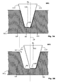
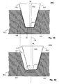
- FIGS. 3A and 3B A first method is described which primarily involves uniform loading of all right flank cutters 113 and all left flank cutters 112 of a skiving tool 100.
- the use of the head cutting edge 114 of the skiving tool 100 has not been optimized here. It goes into the FIGS. 3A and 3B to the skiving of a first workpiece 50.1 with rotationally symmetric, periodic structure using a WälzWarltechnikmaschines 100, and in the 3C and 3D around the skiving of a second workpiece 50.2 with rotationally symmetric, periodic structure using the same WälzWarltechnikmaschinemaschines 100.
- the figures are highly schematic and show only a tooth gap and a cutting tooth 111 of the WälzWarltechnikmaschinegnes 100.
- FIGS. 3A and 3B the relative positions of the WälzCltechnikmaschines 100 and workpiece 50.1 and in the 3C and 3D to make the relative positions of WälzWarltechnikmaschines 100 and workpiece 50.2 recognizable.
- ML represents the center line of the cutting tooth 111.
- the imaginary space center is indicated by the line LM.
- a thick, dotted line shows in schematic form those portions of the cutting tooth 111 which remove material on the workpiece 50.1 or 50.2 at the moment shown.
- teeth or other periodic structures may also be asymmetrical in all embodiments of the invention, although symmetrical structures are shown in the drawings for the sake of simplicity.
- the head cutting edge 114 has a width (in the plane of the drawing) which corresponds approximately to half the foot width of the tooth root 55 of the tooth gap 52 to be produced. This dimensioning causes the head cutting edge 114 to be used twice during machining of the first workpiece 50. 1 during the first processing phase (FIG. Fig. 3A ) and the second processing phase ( Fig. 3B ). In the case of the second workpiece 50.2, the head cutting edge 114 is also used twice accordingly.
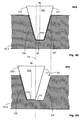
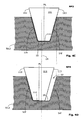
- FIGS. 4A and 4B A second method is described in which it is not only about a uniform load on all right flank cutting edge 113 and all left flank cutting edge 112 of a skiving tool 100.
- the use of the head cutting edge 114 of the skiving tool 100 has here been subjected to an optimization. It goes in the FIGS. 4A and 4B to the skiving of a first workpiece 50.1 with rotationally symmetric, periodic structure using a WälzWarltechnikmaschines 100, and in the Figs. 4C and 4D to skive peeling of a second workpiece 50.2 having a rotationally symmetric, periodic structure using the same skiving tool 100.
- Figs. 4A to 4D essentially the Fig. 3A to 3D correspond to the description of the Fig. 3A to 3D directed. In the following, only the essential differences are treated. Based on Fig. 4B and 4D It can be seen that the head cutting edge 114 has a width which corresponds approximately to 2/3 of the gap width at the tooth root 55.
- Fig. 4B During the second processing phase, the right flank 54f is finished. In addition, approximately the right third of the gap width on the tooth base 55 is finished. In the second processing phase, the in Fig. 4B is shown, only the right edge cutting 113 and at most the right half of the head cutting edge 114 are used, as can be seen here with reference to a thick, dotted line.
- Fig. 4D During the fourth processing phase, the left flank 53f is finished. In addition, approximately the left third of the gap width on the tooth base 55 is finished. In the fourth processing phase, the in Fig. 4D is shown, only the left flank cutting edge 112 and at most the left half of the head cutting edge 114 are used, as can be seen here with reference to a thick, dotted line.
- the cutting tooth 111 may be part of a skiving tool 100 configured as a solid tool, a bar blade tool or an insert tool.
- FIGS. 3A and 3B show representations that approximate the situation in the FIGS. 3A and 3B correspond.
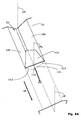
- Fig. 5A is a section of a workpiece 50.1 to recognize in a plan view, wherein the position of a cutting tooth 111 when passing through a tooth gap 52 is shown in a highly schematic form.
- the feed direction VR extends in the gap direction and is composed of the axial feed and a differential feed of the workpiece 50.1 coupled thereto.
- the cutting direction SR here forms an acute angle with the feed direction VR.
- Fig. 5A shows a schematic snapshot eg during the first processing phase.
- the flank cutting edges 112, 113 and the head cutting edge 114 are in Fig. 5A shown dashed lines, since these elements of the cutting tooth 111 are covered by the material of the workpiece 50.1. In the moment shown, both the flank cutting edges 112, 113 and the head cutting edge 114 are used.
- Fig. 5B shows a schematic snapshot eg during the second processing phase.
- the flank cutting edge 112 is visible. From the edge cutting edge 113 only a small portion is visible.
- the head cutter 114 is in Fig. 5B obscured by the material of the workpiece 50.1.
- auxiliary lines LM and ML drawn their meaning in connection with the FIGS. 3A to 3D was explained.
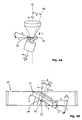
- Fig. 6 shows a portion of a second workpiece 50.2 in the invention skiving, wherein it can be seen how a knife bar 120 is guided with cutting tooth 111 through a tooth gap 52.
- the skiving tool 100 (called bar tool), the in Fig. 6 is not shown, comprises a main body for receiving a plurality of knife bars 120. Here, however, only one knife bar 120 of the WälzCltechnikmaschines 100 is shown.
- each cutting tooth 111 has a rake surface 121, wherein all rake surfaces 121 preferably with respect to the Rotation axis R 1 of the tool 100 are arranged rotationally symmetrical on an end-face plane or on a frontal conical surface (possibly tilted individually about the end plane or conical surface by a stair angle).
- clamping surfaces 121 are preferably arranged rotationally symmetrically with respect to the axis of rotation R1 of the tool 100 on a frontal conical surface, which can degenerate to a frontal plane.
- the rake surfaces 121 may be formed as flat surfaces or as slightly curved surfaces on the cutting heads (cutting teeth 111).
- the rake surfaces 121 may also be slightly curved with respect to a rake face reference plane.
- the two axes of rotation R1 and R2 are always skewed.
- the axis cross angle ⁇ is thus always not equal to zero here.
- the tools 100 may be tilted in the direction of the workpiece 50.1, 50.2 or tilted away from the workpiece 50.1, 50.2 during skiving.
- the appropriate tilting of the tool 100 is optional. It generally serves collision avoidance.
- the corresponding inclination angle is designated by ⁇ . Details about tilts are described, for example, in the copending application of the present applicant, filed on 26.5.2011 under the application number EP11167703.5 filed with the European Patent Office.
- the inclination angle ⁇ is in the range of -30 degrees to +30 degrees.
- Fig. 7 3 is a highly schematic view of a tapered skiving tool 100 which may be used in the context of the invention at an inclination angle ⁇ of -20 degrees.
- the skiving tool 100 is a so-called cutter head tool having a cutter head body 110 (here with a frustoconical (conical) shape), which is equipped with blade inserts, preferably in the form of bar blades 120.
- the skiving tool 100 is moved by means of a tool spindle 170, which is shown here in a highly schematic manner, is connected in terms of motion with a machine 200.
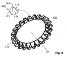
- the skiving tool 100 may have a different shape, such as in Fig. 8 hinted at.
- Fig. 8 For example, there is shown a skiving tool 100 that is in the form of a cutting wheel. This is a solid tool in which the cutting teeth 111 are part of the skiving tool 100.
- the skiving tool 100 here has 24 cutting teeth 111, of which in Fig. 8 one is provided with a reference numeral.
- the main body of the WälzWarltechnikmaschines 100 here has the shape of a truncated cone or a frusto-conical plate.
- a single cutting tooth 111 is shown in enlarged form next to the skiving tool 100. At this cutting tooth 111, the edge cutting edges 112, 113, the head cutting edge 114 and the clamping surface 121 are designated.
- Fig. 9A shows another skiving tool 100, which can be used in connection with the invention.
- the rake faces 121 of the cutting teeth 111 are here arranged on a conical surface (possibly tilted).
- Fig. 9B shows the skiving tool 100 after Fig. 9A in engagement with a cylindrical workpiece 50.1 or 50.2.
- the skiving tool 100 is here inclined away from the workpiece 50.1, 50.2 with a clear inclination angle ⁇ .
- the inclination angle ⁇ here is about 20 degrees.
- Skiving tool 100 shown has the shape of a straight bevel gear, the teeth of this bevel gear represent the cutting teeth 111.
- the clamping surfaces 121 are located on the front side with the smaller diameter. More precisely, the rake surfaces 121 are arranged on the supplementary cone, ie on a conical surface (possibly tilted with respect thereto).
- the helix angle ⁇ 1 of the illustrated skiving tool 100 is 0 degrees. For helix angle ß 1 not equal to 0 degrees a corresponding skiving tool 100 has the basic shape of a helical bevel gear.
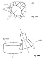
- Fig. 10A shows another skiving tool 100, which can be used in connection with the invention.
- the rake faces 121 of the cutting teeth 111 are here arranged on a conical surface (possibly tilted).
- Fig. 10B shows the skiving tool 100 after Fig. 10A in engagement with a cylindrical workpiece 50.1 or 50.2.
- the skiving tool 100 is here inclined with a clear inclination angle ⁇ to the workpiece 50.1, 50.2.
- the inclination angle ⁇ here is about -18 degrees.
- Skiving tool 100 shown has the shape of a straight bevel gear, the teeth of this bevel gear represent the cutting teeth 111.
- the clamping surfaces 121 are located on the front side with the larger diameter. More precisely, the rake surfaces 121 are arranged on the supplementary cone, ie on a conical surface (possibly tilted with respect thereto).
- the helix angle ⁇ 1 of the illustrated tool 100 is zero degrees. For helix angles other than zero degrees, a corresponding skiving tool 100 has the basic shape of a helical bevel gear.
- Fig. 11 shows a schematic perspective view of a portion of a so-called inner skiving ring 100 in the inner roller peel a straight toothed workpiece 50.1 or 50.2, with only a few blade rods 120 of the inner skiving ring 100 are shown.
- the teeth 51 respectively the tooth spaces 52 between the teeth 51 are already almost completed.
- the annular body of the inner skiving ring 100 has been hidden.
- Fig. 11 is easy to see how the slender shanks (shown here with a rectangular cross-section) of the knife bars 120 can be arranged easily and collision-free in an annular base body.
- the cutting tooth 111 and the rake face 121 are designated.
- the rake surfaces 121 of the cutting teeth 111 are slightly tilted in the example shown with respect to the end plane.
- a machine 200 which is designed for inventive alternating semi-completing skiving, has a CNC controller 201, which allows coupling of the axes R1 and R2, respectively, a coordination of the axis movements.
- the CNC controller 201 may be part of the machine 200, or may be external and configured for communication link 202 to the machine 200.
- the corresponding machine 200 comprises a so-called “electronic gear train”, respectively an “electronic or control-axis coupling" to perform a feed movement VB of WälzWarltechnikmaschineschwmaschines 100 with respect to the workpiece 50.1 or 50.2 (in the example 50.1 or 50.2 workpiece is in the example shown an internally toothed workpiece).
- the coupled movement of the WälzClwerkmaschines 100 and the workpiece 50.1, 50.2 is carried out so that during the various processing phases corresponding relative movements between the WälzCltechnikmaschine 100 and the workpiece 50.1, 50.2 result, which correspond to the relative movements of a fferradgetriebes.
- the electronic gear train, respectively the electronic or control-technical axis coupling ensure a rotational speed synchronization of at least two axes of the machine 200.
- at least the rotation axis R1 of the tool spindle 170 is coupled to the rotation axis R2 of the workpiece spindle 180.
- the rotation axis R1 of the tool spindle 170 is preferably coupled to the axial feed movement VB in the direction R2.
- This axial feed movement VB results from a superposition of movements 204 (vertical) and 208 (horizontal).
- the workpiece spindle 180 can be linearly displaced by means of a (rotary) carriage 205 parallel to a pivot axis SA, as represented by a double arrow 206.
- the (rotary) carriage 205 together with the workpiece spindle 180 and workpiece 50.1, 50.2 can be rotated about the pivot axis SA, as represented by a double arrow 207.
- the axis cross angle ⁇ can be set become.
- the axial distance of the rotation axes R1 and R2 can be adjusted by the linear displacement movement 206.
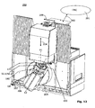
- a machine 200 based on a vertical arrangement is used, as in FIG Fig. 12 shown.
- a vertical arrangement either the skiving tool 100 together with the tool spindle 170 sits above the workpiece 50.1, 50.2 together with the workpiece spindle 180, or vice versa.
- the shavings that occur during skiving fall down due to the effect of gravity and can be removed, for example, over a chip bed, which is not shown.
- the WälzCl snake described can be used dry or wet in all embodiments, the use of WälzSlens in the dry is preferred.
Claims (11)
- Procédé de rabotage à la fraise-mère d'une première pièce (50.1) et d'une seconde pièce (50.2) avec des structures périodiques à symétrie de rotation en utilisant un outil de décolletage (100), comportant les étapes suivantes :- Préparation d'une première pièce (50.1),* déplacement vers une première position relative (RP1) de l'outil de décolletage (100) par rapport à la première pièce (50.1),* exécution d'un premier usinage de rabotage à la fraise-mère de la première pièce (50.1), dans lequel pendant le premier usinage de rabotage à la fraise-mère, tous les flancs de droite (54) ou tous les flancs de gauche (53) de la structure périodique de la première pièce (50.1) sont usinés et les autres flancs respectifs (53 ; 54) sont pré-usinés,* déplacement vers une seconde position relative (RP2) de l'outil de rabotage à la fraise-mère (100) par rapport à la première pièce (50.1),* exécution d'un second usinage de rabotage à la fraise-mère de la première pièce (50.1), dans lequel pendant le second usinage de rabotage à la fraise-mère, les flancs respectifs (53 ; 54) de la structure périodique de la première pièce (50.1) qui avaient précédemment uniquement été pré-usinés pendant le premier usinage de rabotage à la fraise-mère, sont usinés,- Préparation de la seconde pièce (50.2),* déplacement vers une troisième position relative (RP3) de l'outil de rabotage à la fraise-mère (100) par rapport à la seconde pièce (50.2),* exécution d'un troisième usinage de rabotage à la fraise-mère de la seconde pièce (50.2), dans lequel pendant le troisième usinage de rabotage à la fraise-mère- tous les flancs de droite (54) de la structure périodique de la seconde pièce (50.2) sont usinés et tous les flancs de gauche (53) sont pré-usinés dans le cas où lors de l'exécution du premier usinage de rabotage à la fraise-mère sur la première pièce (50.1), tous les flancs de gauche (53) de la structure périodique avaient été usinés,- ou tous les flancs de gauche (53) de la structure périodique de la seconde pièce (50.2) sont usinés et tous les flancs de droite (54) sont pré-usinés dans le cas où lors de l'exécution du premier usinage de rabotage à la fraise-mère sur la première pièce (50.1), tous les flancs de droite (54) de la structure périodique avaient été usinés,* déplacement vers une quatrième position relative (RP4) de l'outil de rabotage à la fraise-mère (100) par rapport à la seconde pièce (50.2),* exécution d'un quatrième usinage de rabotage à la fraise-mère de la seconde pièce (50.2), dans lequel pendant le quatrième usinage de rabotage à la fraise-mère, les flancs respectifs (53 ; 54) de la structure périodique de la seconde pièce (50.2) qui n'avaient été précédemment que pré-usinés lors du troisième usinage de rabotage à la fraise-mère sont usinés.
- Procédé selon la revendication 1, dans lequel le premier usinage de rabotage à la fraise-mère et le second usinage de rabotage à la fraise-mère de la première pièce (50.1) comportent les étapes suivantes :- pivotement de l'outil de rabotage à la fraise-mère (100) autour d'un premier axe de rotation (R1),- pivotement couplé de la première pièce (50.1) autour d'un second axe de rotation (R2), et- exécution d'un mouvement de poussée axial (VB) de l'outil de rabotage à la fraise-mère (100) vis-à-vis de la première pièce (50.1) dans une direction parallèle au second axe de rotation (R2).
- Procédé selon la revendication 1 ou 2, dans lequel le troisième usinage de rabotage à la fraise-mère et le quatrième usinage de rabotage à la fraise-mère de la seconde pièce (50.2) comportent les étapes suivantes :- pivotement de l'outil de rabotage à la fraise-mère (100) autour d'un premier axe de rotation (R1),- pivotement couplé de la seconde pièce (50.2) autour d'un second axe de rotation (R2), et- exécution d'un mouvement de poussée axial (VB) de l'outil de rabotage à la fraise-mère (100) vis-à-vis de la seconde pièce (50.2) dans une direction parallèle au second axe de rotation (R2).
- Procédé selon la revendication 1, 2 ou 3, caractérisé en ce que l'outil de rabotage à la fraise-mère (100) comporte plusieurs dents coupantes (111), où chaque dent coupante (111) a une premier arête de coupe latérale (113) destiné à couper les flancs de droite (54), une second arête de coupe latérale (112) destiné à couper les flancs de gauche (53) et une arête de coupe de tête (114), qui repose dans une zone de transition entre la premier arête de coupe latérale (113) et la second arête de coupe latérale (112).
- Procédé selon la revendication 4, caractérisé en ce que les usinages de rabotage à la fraise-mère de la première pièce (50.1) et de la seconde pièce (50.2) sont exécutés de façon telle que le nombre des coupes qui sont exécutées avec la premier arête de coupe latérale (113) et le nombre de coupes qui sont exécutées avec la second arête de coupe latérale (112) sont approximativement identiques.
- Procédé selon la revendication 4 ou 5, caractérisé en ce que l'arête de coupe de tête (114) a une largeur qui est inférieure à la largeur d'entredent au niveau du pied de dent (55) des entredents (52) à usiner au niveau de la première pièce (50.1) et au niveau de la seconde pièce (50.2), l'arête de coupe de tête (114) ayant de préférence une largeur qui est inférieure ou égale à 2/3 de la largeur du creux au niveau du pied de dent (55).
- Procédé selon l'une des revendications 1 à 6 précédentes, caractérisé en ce qu'au moins deux des positions relatives (RP1, RP2, RP3, RP4) se distinguent par une rotation angulaire de la première pièce (50.1) ou de la seconde pièce (50.2).
- Procédé selon l'une des revendications 1 à 6 précédentes, caractérisé en ce que la deuxième position relative (RP2) correspond à la troisième position relative (RP3) et la première position relative (RP1) à la quatrième position relative (RP4).
- Procédé selon l'une des revendications 1 à 8 précédentes, caractérisé en ce que les usinages de rabotage à la fraise-mère sont exécutés sur des pièces (50.1, 50.2) douces, à savoir non trempées.
- Machine (200) comportant une commande CNC (201), qui est programmée pour exécuter un procédé selon l'une des revendications 1 à 9 précédentes.
- Machine (200) selon la revendication 10, caractérisée en ce qu'elle comporte un module logiciel qui est programmé de façon telle que lors du rabotage à la fraise-mère, un processus de Semi-Completing en alternance est prédéfini afin de garantir une charge de coupe la plus régulière possible des lames (112, 113, 114) de l'outil de rabotage à la fraise-mère (100).
Priority Applications (8)
| Application Number | Priority Date | Filing Date | Title |
|---|---|---|---|
| EP11181521.3A EP2570217B1 (fr) | 2011-09-15 | 2011-09-15 | Procédé d'écroutage semi-complet et dispositif doté d'un outil d'écroutage associé pour développer un procédé d'écroutage semi-complet |
| RU2012137693/02A RU2584838C2 (ru) | 2011-09-15 | 2012-09-04 | Способ зуботочения и станок для его осуществления |
| MX2012010510A MX2012010510A (es) | 2011-09-15 | 2012-09-11 | Metodo de torneado semiterminado y dispositivo que tiene la herramienta de torneado correspondiente para ejecutar un metodo de torneado semiterminado. |
| BR102012023164-6A BR102012023164B1 (pt) | 2011-09-15 | 2012-09-13 | método para desbastar uma primeira peça de trabalho e uma segunda peça de trabalho, e, máquina |
| US13/617,277 US9199323B2 (en) | 2011-09-15 | 2012-09-14 | Semi-completing skiving method and device having corresponding skiving tool for executing a semi-completing skiving method |
| CN201210342443.XA CN102990165B (zh) | 2011-09-15 | 2012-09-14 | 半完成切削的方法以及执行该方法的相应切削刀具的装置 |
| KR1020120102025A KR101976847B1 (ko) | 2011-09-15 | 2012-09-14 | 세미 컴플리팅 스카이빙 방법 및 세미 컴플리팅 스카이빙 방법을 실행하기 위한 대응하는 스카이빙 공구를 갖춘 장치 |
| JP2012204456A JP5908818B2 (ja) | 2011-09-15 | 2012-09-18 | 半完結スカイビング法を実行するための対応するスカイビングツールを有する半完結スカイビング加工の方法および装置 |
Applications Claiming Priority (1)
| Application Number | Priority Date | Filing Date | Title |
|---|---|---|---|
| EP11181521.3A EP2570217B1 (fr) | 2011-09-15 | 2011-09-15 | Procédé d'écroutage semi-complet et dispositif doté d'un outil d'écroutage associé pour développer un procédé d'écroutage semi-complet |
Publications (2)
| Publication Number | Publication Date |
|---|---|
| EP2570217A1 EP2570217A1 (fr) | 2013-03-20 |
| EP2570217B1 true EP2570217B1 (fr) | 2014-11-05 |
Family
ID=44905394
Family Applications (1)
| Application Number | Title | Priority Date | Filing Date |
|---|---|---|---|
| EP11181521.3A Active EP2570217B1 (fr) | 2011-09-15 | 2011-09-15 | Procédé d'écroutage semi-complet et dispositif doté d'un outil d'écroutage associé pour développer un procédé d'écroutage semi-complet |
Country Status (8)
| Country | Link |
|---|---|
| US (1) | US9199323B2 (fr) |
| EP (1) | EP2570217B1 (fr) |
| JP (1) | JP5908818B2 (fr) |
| KR (1) | KR101976847B1 (fr) |
| CN (1) | CN102990165B (fr) |
| BR (1) | BR102012023164B1 (fr) |
| MX (1) | MX2012010510A (fr) |
| RU (1) | RU2584838C2 (fr) |
Families Citing this family (31)
| Publication number | Priority date | Publication date | Assignee | Title |
|---|---|---|---|---|
| DE102012022439A1 (de) * | 2012-11-16 | 2014-05-22 | Marcel Sobczyk | Verfahren zur Bestimmung der Freiflächenkontur eines Wälzschälwerkzeuges, Wälzschälwerkzeug und dessen Verwendung |
| EP2792442B1 (fr) * | 2013-04-17 | 2018-08-22 | Klingelnberg AG | Outil d'écroutage pour l'écroutage d'une denture sur une pièce à couronne dentée |
| EP2988898B1 (fr) | 2013-04-22 | 2019-01-16 | The Gleason Works | Taillage de roues cylindriques |
| DE102013109981A1 (de) * | 2013-07-19 | 2015-01-22 | Profilator Gmbh & Co. Kg | Wälzschälverfahren und zugehörige Vorrichtung |
| CA2934939C (fr) * | 2013-09-11 | 2021-06-08 | Profilator Gmbh & Co. Kg | Procede de decolletage en developpante, et dispositif correspondant |
| DE102013015252A1 (de) * | 2013-09-13 | 2015-03-19 | Gleason-Pfauter Maschinenfabrik Gmbh | Kühlmittelzufuhr und damit ausgestattete Wälzschälmaschine sowie damit ausgeführtes Wälzschälverfahren |
| JP2015089600A (ja) * | 2013-11-06 | 2015-05-11 | 株式会社ジェイテクト | 歯車加工方法、段付き歯車、および遊星歯車機構 |
| DE102014108438A1 (de) * | 2014-06-16 | 2015-12-17 | Profilator Gmbh & Co. Kg | Verfahren zum Einarbeiten von Hinterlegungen in Zahnflanken der Zähne von Zahnrädern |
| DE102015104310A1 (de) * | 2015-03-23 | 2016-09-29 | Profilator Gmbh & Co. Kg | Verfahren und Vorrichtung zum Verzahnen eines Werkrades mit vermindertem Flankenlinienformfehler |
| DE102015104500A1 (de) * | 2015-03-25 | 2016-09-29 | Profilator Gmbh & Co. Kg | Verfahren und Vorrichtung zum Verzahnen von Werkrädern durch Wälzschälen |
| USD802037S1 (en) * | 2015-06-11 | 2017-11-07 | Christopher Cordingley | Gear and axle combination |
| DE102015121523A1 (de) * | 2015-12-10 | 2017-06-14 | Profilator Gmbh & Co. Kg | Vorrichtung und Verfahren zum Schrupp- und Feinbearbeiten von Zahnrädern |
| JP6720543B2 (ja) * | 2016-01-14 | 2020-07-08 | アイシン精機株式会社 | 歯車加工方法 |
| JP6979756B2 (ja) * | 2016-03-07 | 2021-12-15 | セイコーインスツル株式会社 | 歯車加工装置、及び歯車加工方法 |
| DE102016113512A1 (de) | 2016-07-21 | 2018-01-25 | Profilator Gmbh & Co. Kg | Verfahren zur Fertigung eines einsatzgehärteten Zahnrades, insbesondere mit einer Innenverzahnung |
| EP3287222A1 (fr) * | 2016-08-23 | 2018-02-28 | Klingelnberg AG | Procédé d'usinage de dentures de pièces d'usinage d'accouplement plan selon un procédé de pièces semi-complètes |
| JP7024303B2 (ja) * | 2016-10-13 | 2022-02-24 | 株式会社ジェイテクト | 歯車加工装置及び歯車加工方法 |
| EP3375555A1 (fr) * | 2017-03-17 | 2018-09-19 | Klingelnberg AG | Procédé de traitement des flancs de dent de pièces de roue dentée conique |
| DE102017006651A1 (de) * | 2017-07-13 | 2019-01-17 | Gleason-Pfauter Maschinenfabrik Gmbh | Verfahren zum Erzeugen eines verzahnten Werkstücks |
| CH714443B1 (de) * | 2017-12-15 | 2020-10-15 | Reishauer Ag | Verfahren und Vorrichtung zur Vermessung eines Wälzbearbeitungswerkzeugs. |
| DE102018112865B3 (de) * | 2018-05-29 | 2019-10-17 | Hartmetall-Werkzeugfabrik Paul Horn Gmbh | Wälzschälwerkzeug |
| CN108941792A (zh) * | 2018-08-04 | 2018-12-07 | 王飞 | 一种齿轮加工机床定距拉杆 |
| US10780512B2 (en) * | 2018-08-24 | 2020-09-22 | Gleason Cutting Tools Corporation | Multi-component gear cutting tool |
| CN109648274A (zh) * | 2018-11-30 | 2019-04-19 | 中国航空工业集团公司金城南京机电液压工程研究中心 | 一种外圆齿廓铲齿加工方法 |
| DE102019102870A1 (de) | 2019-02-05 | 2020-08-06 | Klingelnberg Ag | Verfahren zum Bearbeiten von Zahnrad-Werkstücken |
| CN111090930B (zh) * | 2019-11-28 | 2023-07-21 | 内蒙古民族大学 | 基于Solidworks的剐削切屑几何模型构建方法 |
| CN112453590B (zh) * | 2020-11-25 | 2021-09-21 | 深圳市蓝海永兴实业有限公司 | 一种复合材料弧形齿锥齿轮刮削刀具 |
| WO2022145013A1 (fr) | 2020-12-28 | 2022-07-07 | 株式会社ハーモニック・ドライブ・システムズ | Procédé de traitement de taillage d'engrenages |
| CN112975000B (zh) * | 2021-02-24 | 2022-08-05 | 西安理工大学 | 一种圆柱齿轮精加工刮削刀具设计方法及刮削修形工艺 |
| KR20230027523A (ko) | 2021-08-19 | 2023-02-28 | 주식회사 디엔솔루션즈 | 복합공작기계의 기어 스카이빙 가공 제어방법 |
| CN114433959B (zh) * | 2022-01-24 | 2023-01-10 | 浙江陀曼数字技术有限公司 | 扇形齿轮加工方法及扇形齿轮 |
Family Cites Families (17)
| Publication number | Priority date | Publication date | Assignee | Title |
|---|---|---|---|---|
| DE243514C (de) | 1910-03-01 | 1912-02-16 | George Adams | Verfahren zum schneiden van zahnrädern mittels eines zahnradartigen, an den stirnflächen der zähne mit schneidkanten versehenen schneidwerkzeuges |
| US2091575A (en) * | 1935-07-30 | 1937-08-31 | Gleason Works | Method of cutting gears |
| US2310484A (en) * | 1939-11-21 | 1943-02-09 | Gleason Works | Method of producing gears |
| US2342232A (en) * | 1940-03-19 | 1944-02-22 | Gleason Works | Method and machine for producing gears |
| SU715245A1 (ru) * | 1973-06-25 | 1980-02-15 | Всесоюзный Научно-Исследовательский Инструментальный Институт | Обкаточный резец |
| SU1349114A1 (ru) * | 1984-12-04 | 1994-03-15 | Всесоюзный заочный машиностроительный институт | Станок для обработки цилиндрических зубчатых колес |
| CN1009174B (zh) * | 1987-09-10 | 1990-08-15 | 吉林工业大学 | 齿轮刮削滚刀 |
| SU1715520A1 (ru) * | 1987-11-19 | 1992-02-28 | Всесоюзный заочный машиностроительный институт | Универсальный зубообрабатывающий станок с ЧПУ |
| DE3915976C2 (de) | 1989-05-17 | 2002-01-31 | Pfauter Hermann Gmbh Co | Verfahren zur Schlichtbearbeitung der Flanken von gerad- oder schrägverzahnten, innen- oder außenverzahnten Zylinderrädern durch Wälzschälen sowie Wälzmaschine zur Durchführung eines solchen Verfahrens |
| US5174699A (en) * | 1989-05-17 | 1992-12-29 | Hermann Pfauter Gmbh & Co. | Method for finishing gears via skiving |
| JP2634503B2 (ja) * | 1991-05-14 | 1997-07-30 | 豊精密工業株式会社 | 創成歯切り法 |
| CN1077149A (zh) * | 1992-04-10 | 1993-10-13 | 周永生 | 椭圆齿轮剃、珩齿工作原理及其机床 |
| HUP0103543A2 (hu) | 1998-10-02 | 2002-01-28 | 3M Innovative Properties Company | Nyálkahártyán megtapadó hatóanyag bejuttató rendszerek és ezek alkalmazása állatok kezelésére |
| WO2001039916A1 (fr) * | 1999-12-01 | 2001-06-07 | Lambert Ag | Procede de rectification pour roues coniques a denture droite |
| JP4182137B1 (ja) * | 2007-08-02 | 2008-11-19 | 本田技研工業株式会社 | 歯車加工方法 |
| DE202011050054U1 (de) * | 2011-05-06 | 2011-09-15 | Klingelnberg Ag | Wälzschälwerkzeug mit Messerstäben |
| EP2527072B8 (fr) | 2011-05-26 | 2018-05-23 | Klingelnberg AG | Procédé et dispositif d'écroutage de dentures extérieures, et dispositif avec outil d'écroutage correspondant |
-
2011
- 2011-09-15 EP EP11181521.3A patent/EP2570217B1/fr active Active
-
2012
- 2012-09-04 RU RU2012137693/02A patent/RU2584838C2/ru active
- 2012-09-11 MX MX2012010510A patent/MX2012010510A/es active IP Right Grant
- 2012-09-13 BR BR102012023164-6A patent/BR102012023164B1/pt active IP Right Grant
- 2012-09-14 CN CN201210342443.XA patent/CN102990165B/zh active Active
- 2012-09-14 US US13/617,277 patent/US9199323B2/en not_active Expired - Fee Related
- 2012-09-14 KR KR1020120102025A patent/KR101976847B1/ko active IP Right Grant
- 2012-09-18 JP JP2012204456A patent/JP5908818B2/ja active Active
Also Published As
| Publication number | Publication date |
|---|---|
| MX2012010510A (es) | 2013-03-18 |
| US9199323B2 (en) | 2015-12-01 |
| EP2570217A1 (fr) | 2013-03-20 |
| KR101976847B1 (ko) | 2019-05-09 |
| RU2012137693A (ru) | 2014-03-10 |
| CN102990165B (zh) | 2015-06-10 |
| CN102990165A (zh) | 2013-03-27 |
| KR20130030224A (ko) | 2013-03-26 |
| JP2013063506A (ja) | 2013-04-11 |
| JP5908818B2 (ja) | 2016-04-26 |
| RU2584838C2 (ru) | 2016-05-20 |
| BR102012023164A2 (pt) | 2014-04-15 |
| BR102012023164B1 (pt) | 2021-02-17 |
| US20130071197A1 (en) | 2013-03-21 |
Similar Documents
| Publication | Publication Date | Title |
|---|---|---|
| EP2570217B1 (fr) | Procédé d'écroutage semi-complet et dispositif doté d'un outil d'écroutage associé pour développer un procédé d'écroutage semi-complet | |
| EP2537615B1 (fr) | Procédé robuste de taillage de cylindres | |
| EP2520391B1 (fr) | Procédé de taillage de cylindres | |
| EP3389906B1 (fr) | Dispositif et procédé de chanfreinage d'une roue d'usinage dentée | |
| EP2535134B1 (fr) | Procédé pour pré-tailler plusieurs roues coniques différentes | |
| EP2385885B2 (fr) | Dispositif et procédé pour tailler des dents dans des pièces | |
| EP2665574B9 (fr) | Procédé d'usinage d'une pièce par enlèvement de copeaux, et machine-outil mise au point à cette fin | |
| EP3299105B1 (fr) | Procédé de chanfreinage des roues dentées coniques | |
| EP2954967B1 (fr) | Procédé et dispositif de chanfreinage frontal d'une denture d'une pièce à usiner | |
| EP2792442B1 (fr) | Outil d'écroutage pour l'écroutage d'une denture sur une pièce à couronne dentée | |
| DE10330474A1 (de) | Verfahren, Vorrichtung und Werkzeug zum Anfasen der Stirnkanten der Zahnnuten eines Zahnrades | |
| EP2596893A1 (fr) | Procédé d'écroutage partiel doté de deux angles de croisement d'axe et utilisation d'un outil d'écroutage correspondant pour l'écroutage partiel | |
| WO2012159942A1 (fr) | Procédé de taillage par développante de dentures extérieures et dispositif muni d'un outil de taillage par développante correspondant | |
| EP3230001A1 (fr) | Procédé de traitement d'une denture, ensemble d'outil et machine à denture | |
| EP3034219B1 (fr) | Procédé de décolletage en développante à stratégie à plusieurs coupes | |
| EP3287221B1 (fr) | Procédé de traitement de flancs de dents de pièces d'usinage d'accouplement plan selon un procédé de pièces individuelles semi-complètes | |
| EP2851150B1 (fr) | Outil, procédé et machine destinés à fabriquer un profil denté sur une pièce par taillage des engrenages par développante | |
| DE102017107999A1 (de) | Entgratvorrichtung sowie CNC-Verzahnmaschine mit einer solchen Entgratvorrichtung | |
| EP2537616B1 (fr) | Procédé robuste de taillage de cylindres et dispositif correspondant doté d'un outil de taillage de cylindres | |
| DE20320294U1 (de) | Vorrichtung zur Herstellung eines Zahnrads | |
| EP3287222A1 (fr) | Procédé d'usinage de dentures de pièces d'usinage d'accouplement plan selon un procédé de pièces semi-complètes | |
| EP2527072B1 (fr) | Procédé et dispositif d'écroutage de dentures extérieures, et dispositif avec outil d'écroutage correspondant | |
| EP3517235B1 (fr) | Procédé d'ébarbage de pignons conique et machine à tailler les engrenages cnc pourvue d'un logiciel d'ébarbage correspondant |
Legal Events
| Date | Code | Title | Description |
|---|---|---|---|
| PUAI | Public reference made under article 153(3) epc to a published international application that has entered the european phase |
Free format text: ORIGINAL CODE: 0009012 |
|
| AK | Designated contracting states |
Kind code of ref document: A1 Designated state(s): AL AT BE BG CH CY CZ DE DK EE ES FI FR GB GR HR HU IE IS IT LI LT LU LV MC MK MT NL NO PL PT RO RS SE SI SK SM TR |
|
| AX | Request for extension of the european patent |
Extension state: BA ME |
|
| 17P | Request for examination filed |
Effective date: 20130821 |
|
| RBV | Designated contracting states (corrected) |
Designated state(s): AL AT BE BG CH CY CZ DE DK EE ES FI FR GB GR HR HU IE IS IT LI LT LU LV MC MK MT NL NO PL PT RO RS SE SI SK SM TR |
|
| GRAP | Despatch of communication of intention to grant a patent |
Free format text: ORIGINAL CODE: EPIDOSNIGR1 |
|
| INTG | Intention to grant announced |
Effective date: 20131106 |
|
| RIN1 | Information on inventor provided before grant (corrected) |
Inventor name: VOGEL, OLAF Inventor name: MARX, HARTMUT |
|
| GRAP | Despatch of communication of intention to grant a patent |
Free format text: ORIGINAL CODE: EPIDOSNIGR1 |
|
| INTG | Intention to grant announced |
Effective date: 20140424 |
|
| GRAS | Grant fee paid |
Free format text: ORIGINAL CODE: EPIDOSNIGR3 |
|
| GRAA | (expected) grant |
Free format text: ORIGINAL CODE: 0009210 |
|
| AK | Designated contracting states |
Kind code of ref document: B1 Designated state(s): AL AT BE BG CH CY CZ DE DK EE ES FI FR GB GR HR HU IE IS IT LI LT LU LV MC MK MT NL NO PL PT RO RS SE SI SK SM TR |
|
| REG | Reference to a national code |
Ref country code: GB Ref legal event code: FG4D Free format text: NOT ENGLISH |
|
| REG | Reference to a national code |
Ref country code: CH Ref legal event code: EP |
|
| REG | Reference to a national code |
Ref country code: AT Ref legal event code: REF Ref document number: 694331 Country of ref document: AT Kind code of ref document: T Effective date: 20141115 |
|
| REG | Reference to a national code |
Ref country code: IE Ref legal event code: FG4D Free format text: LANGUAGE OF EP DOCUMENT: GERMAN |
|
| REG | Reference to a national code |
Ref country code: DE Ref legal event code: R096 Ref document number: 502011004869 Country of ref document: DE Effective date: 20141218 |
|
| REG | Reference to a national code |
Ref country code: NL Ref legal event code: T3 |
|
| REG | Reference to a national code |
Ref country code: LT Ref legal event code: MG4D |
|
| PG25 | Lapsed in a contracting state [announced via postgrant information from national office to epo] |
Ref country code: FI Free format text: LAPSE BECAUSE OF FAILURE TO SUBMIT A TRANSLATION OF THE DESCRIPTION OR TO PAY THE FEE WITHIN THE PRESCRIBED TIME-LIMIT Effective date: 20141105 Ref country code: IS Free format text: LAPSE BECAUSE OF FAILURE TO SUBMIT A TRANSLATION OF THE DESCRIPTION OR TO PAY THE FEE WITHIN THE PRESCRIBED TIME-LIMIT Effective date: 20150305 Ref country code: PT Free format text: LAPSE BECAUSE OF FAILURE TO SUBMIT A TRANSLATION OF THE DESCRIPTION OR TO PAY THE FEE WITHIN THE PRESCRIBED TIME-LIMIT Effective date: 20150305 Ref country code: NO Free format text: LAPSE BECAUSE OF FAILURE TO SUBMIT A TRANSLATION OF THE DESCRIPTION OR TO PAY THE FEE WITHIN THE PRESCRIBED TIME-LIMIT Effective date: 20150205 Ref country code: ES Free format text: LAPSE BECAUSE OF FAILURE TO SUBMIT A TRANSLATION OF THE DESCRIPTION OR TO PAY THE FEE WITHIN THE PRESCRIBED TIME-LIMIT Effective date: 20141105 Ref country code: LT Free format text: LAPSE BECAUSE OF FAILURE TO SUBMIT A TRANSLATION OF THE DESCRIPTION OR TO PAY THE FEE WITHIN THE PRESCRIBED TIME-LIMIT Effective date: 20141105 |
|
| PG25 | Lapsed in a contracting state [announced via postgrant information from national office to epo] |
Ref country code: GR Free format text: LAPSE BECAUSE OF FAILURE TO SUBMIT A TRANSLATION OF THE DESCRIPTION OR TO PAY THE FEE WITHIN THE PRESCRIBED TIME-LIMIT Effective date: 20150206 Ref country code: LV Free format text: LAPSE BECAUSE OF FAILURE TO SUBMIT A TRANSLATION OF THE DESCRIPTION OR TO PAY THE FEE WITHIN THE PRESCRIBED TIME-LIMIT Effective date: 20141105 Ref country code: RS Free format text: LAPSE BECAUSE OF FAILURE TO SUBMIT A TRANSLATION OF THE DESCRIPTION OR TO PAY THE FEE WITHIN THE PRESCRIBED TIME-LIMIT Effective date: 20141105 Ref country code: SE Free format text: LAPSE BECAUSE OF FAILURE TO SUBMIT A TRANSLATION OF THE DESCRIPTION OR TO PAY THE FEE WITHIN THE PRESCRIBED TIME-LIMIT Effective date: 20141105 Ref country code: HR Free format text: LAPSE BECAUSE OF FAILURE TO SUBMIT A TRANSLATION OF THE DESCRIPTION OR TO PAY THE FEE WITHIN THE PRESCRIBED TIME-LIMIT Effective date: 20141105 Ref country code: PL Free format text: LAPSE BECAUSE OF FAILURE TO SUBMIT A TRANSLATION OF THE DESCRIPTION OR TO PAY THE FEE WITHIN THE PRESCRIBED TIME-LIMIT Effective date: 20141105 Ref country code: CY Free format text: LAPSE BECAUSE OF FAILURE TO SUBMIT A TRANSLATION OF THE DESCRIPTION OR TO PAY THE FEE WITHIN THE PRESCRIBED TIME-LIMIT Effective date: 20141105 |
|
| PG25 | Lapsed in a contracting state [announced via postgrant information from national office to epo] |
Ref country code: EE Free format text: LAPSE BECAUSE OF FAILURE TO SUBMIT A TRANSLATION OF THE DESCRIPTION OR TO PAY THE FEE WITHIN THE PRESCRIBED TIME-LIMIT Effective date: 20141105 Ref country code: SK Free format text: LAPSE BECAUSE OF FAILURE TO SUBMIT A TRANSLATION OF THE DESCRIPTION OR TO PAY THE FEE WITHIN THE PRESCRIBED TIME-LIMIT Effective date: 20141105 Ref country code: DK Free format text: LAPSE BECAUSE OF FAILURE TO SUBMIT A TRANSLATION OF THE DESCRIPTION OR TO PAY THE FEE WITHIN THE PRESCRIBED TIME-LIMIT Effective date: 20141105 Ref country code: CZ Free format text: LAPSE BECAUSE OF FAILURE TO SUBMIT A TRANSLATION OF THE DESCRIPTION OR TO PAY THE FEE WITHIN THE PRESCRIBED TIME-LIMIT Effective date: 20141105 |
|
| REG | Reference to a national code |
Ref country code: DE Ref legal event code: R097 Ref document number: 502011004869 Country of ref document: DE |
|
| PLBE | No opposition filed within time limit |
Free format text: ORIGINAL CODE: 0009261 |
|
| STAA | Information on the status of an ep patent application or granted ep patent |
Free format text: STATUS: NO OPPOSITION FILED WITHIN TIME LIMIT |
|
| 26N | No opposition filed |
Effective date: 20150806 |
|
| PG25 | Lapsed in a contracting state [announced via postgrant information from national office to epo] |
Ref country code: SI Free format text: LAPSE BECAUSE OF FAILURE TO SUBMIT A TRANSLATION OF THE DESCRIPTION OR TO PAY THE FEE WITHIN THE PRESCRIBED TIME-LIMIT Effective date: 20141105 |
|
| PG25 | Lapsed in a contracting state [announced via postgrant information from national office to epo] |
Ref country code: MC Free format text: LAPSE BECAUSE OF FAILURE TO SUBMIT A TRANSLATION OF THE DESCRIPTION OR TO PAY THE FEE WITHIN THE PRESCRIBED TIME-LIMIT Effective date: 20141105 Ref country code: LU Free format text: LAPSE BECAUSE OF FAILURE TO SUBMIT A TRANSLATION OF THE DESCRIPTION OR TO PAY THE FEE WITHIN THE PRESCRIBED TIME-LIMIT Effective date: 20150915 |
|
| PG25 | Lapsed in a contracting state [announced via postgrant information from national office to epo] |
Ref country code: RO Free format text: LAPSE BECAUSE OF FAILURE TO SUBMIT A TRANSLATION OF THE DESCRIPTION OR TO PAY THE FEE WITHIN THE PRESCRIBED TIME-LIMIT Effective date: 20141105 |
|
| REG | Reference to a national code |
Ref country code: IE Ref legal event code: MM4A |
|
| PG25 | Lapsed in a contracting state [announced via postgrant information from national office to epo] |
Ref country code: IE Free format text: LAPSE BECAUSE OF NON-PAYMENT OF DUE FEES Effective date: 20150915 |
|
| REG | Reference to a national code |
Ref country code: FR Ref legal event code: PLFP Year of fee payment: 6 |
|
| PG25 | Lapsed in a contracting state [announced via postgrant information from national office to epo] |
Ref country code: MT Free format text: LAPSE BECAUSE OF FAILURE TO SUBMIT A TRANSLATION OF THE DESCRIPTION OR TO PAY THE FEE WITHIN THE PRESCRIBED TIME-LIMIT Effective date: 20141105 |
|
| PG25 | Lapsed in a contracting state [announced via postgrant information from national office to epo] |
Ref country code: SM Free format text: LAPSE BECAUSE OF FAILURE TO SUBMIT A TRANSLATION OF THE DESCRIPTION OR TO PAY THE FEE WITHIN THE PRESCRIBED TIME-LIMIT Effective date: 20141105 Ref country code: BG Free format text: LAPSE BECAUSE OF FAILURE TO SUBMIT A TRANSLATION OF THE DESCRIPTION OR TO PAY THE FEE WITHIN THE PRESCRIBED TIME-LIMIT Effective date: 20141105 Ref country code: HU Free format text: LAPSE BECAUSE OF FAILURE TO SUBMIT A TRANSLATION OF THE DESCRIPTION OR TO PAY THE FEE WITHIN THE PRESCRIBED TIME-LIMIT; INVALID AB INITIO Effective date: 20110915 |
|
| PG25 | Lapsed in a contracting state [announced via postgrant information from national office to epo] |
Ref country code: TR Free format text: LAPSE BECAUSE OF FAILURE TO SUBMIT A TRANSLATION OF THE DESCRIPTION OR TO PAY THE FEE WITHIN THE PRESCRIBED TIME-LIMIT Effective date: 20141105 |
|
| REG | Reference to a national code |
Ref country code: FR Ref legal event code: PLFP Year of fee payment: 7 |
|
| PG25 | Lapsed in a contracting state [announced via postgrant information from national office to epo] |
Ref country code: MK Free format text: LAPSE BECAUSE OF FAILURE TO SUBMIT A TRANSLATION OF THE DESCRIPTION OR TO PAY THE FEE WITHIN THE PRESCRIBED TIME-LIMIT Effective date: 20141105 |
|
| REG | Reference to a national code |
Ref country code: FR Ref legal event code: PLFP Year of fee payment: 8 |
|
| PG25 | Lapsed in a contracting state [announced via postgrant information from national office to epo] |
Ref country code: AL Free format text: LAPSE BECAUSE OF FAILURE TO SUBMIT A TRANSLATION OF THE DESCRIPTION OR TO PAY THE FEE WITHIN THE PRESCRIBED TIME-LIMIT Effective date: 20141105 |
|
| PGFP | Annual fee paid to national office [announced via postgrant information from national office to epo] |
Ref country code: NL Payment date: 20220920 Year of fee payment: 12 Ref country code: GB Payment date: 20220920 Year of fee payment: 12 Ref country code: DE Payment date: 20220920 Year of fee payment: 12 Ref country code: AT Payment date: 20220921 Year of fee payment: 12 |
|
| PGFP | Annual fee paid to national office [announced via postgrant information from national office to epo] |
Ref country code: FR Payment date: 20220922 Year of fee payment: 12 Ref country code: BE Payment date: 20220920 Year of fee payment: 12 |
|
| PGFP | Annual fee paid to national office [announced via postgrant information from national office to epo] |
Ref country code: IT Payment date: 20220926 Year of fee payment: 12 |
|
| PGFP | Annual fee paid to national office [announced via postgrant information from national office to epo] |
Ref country code: CH Payment date: 20220928 Year of fee payment: 12 |