EP2570200A2 - Robotic apparatus for the surface treatment, in particular cleaning of rotating rollers - Google Patents
Robotic apparatus for the surface treatment, in particular cleaning of rotating rollers Download PDFInfo
- Publication number
- EP2570200A2 EP2570200A2 EP12184411A EP12184411A EP2570200A2 EP 2570200 A2 EP2570200 A2 EP 2570200A2 EP 12184411 A EP12184411 A EP 12184411A EP 12184411 A EP12184411 A EP 12184411A EP 2570200 A2 EP2570200 A2 EP 2570200A2
- Authority
- EP
- European Patent Office
- Prior art keywords
- robotic apparatus
- rotating rollers
- speed
- advancement
- abrasive
- Prior art date
- Legal status (The legal status is an assumption and is not a legal conclusion. Google has not performed a legal analysis and makes no representation as to the accuracy of the status listed.)
- Granted
Links
Images



Classifications
-
- B—PERFORMING OPERATIONS; TRANSPORTING
- B08—CLEANING
- B08B—CLEANING IN GENERAL; PREVENTION OF FOULING IN GENERAL
- B08B1/00—Cleaning by methods involving the use of tools
- B08B1/30—Cleaning by methods involving the use of tools by movement of cleaning members over a surface
-
- B—PERFORMING OPERATIONS; TRANSPORTING
- B08—CLEANING
- B08B—CLEANING IN GENERAL; PREVENTION OF FOULING IN GENERAL
- B08B1/00—Cleaning by methods involving the use of tools
- B08B1/30—Cleaning by methods involving the use of tools by movement of cleaning members over a surface
- B08B1/32—Cleaning by methods involving the use of tools by movement of cleaning members over a surface using rotary cleaning members
- B08B1/34—Cleaning by methods involving the use of tools by movement of cleaning members over a surface using rotary cleaning members rotating about an axis parallel to the surface
Definitions
- the navigation device 15 includes a processing and driving module that, depending on the position indicated by the absolute transducer means and, taking account of the angular speed or of the peripheral speed Vr of the rotating rollers 2, accordingly drives the first 4a and second 4b advancement means in a selective and mutually differentiated manner to generate a desired advancement of the robotic apparatus 1 both in a transverse direction and in a longitudinal direction on the train of rotating rollers 2, so as to enable the abrasive elements 5 to treat the entire cylindrical surface of each underlying rotating roller 2 and/or possible further upper rollers 2a placed above the robotic apparatus 1 (as shown in Figure 6 ).
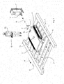
- the suitably programmed transmission module 17 emits a laser beam 18 varying in a controlled manner the direction thereof, as indicated by the arrow F in Figures 1 and 2 .
- the laser beam 18 is moved in a direction parallel to the longitudinal axes X of the rollers 2, in a manner alternating first in one direction and then in the other.
- the navigation device 15 by detecting the variation in the direction of the laser beam 18 hitting the receiving module 16, adjusts the driving speed of each of the tracked elements 4 in an appropriate manner, in such a manner as to rotate the apparatus 1 and orientate it relative to the rollers 2.
- an operating method is disclosed for cleaning the rotating rollers 2 by the robotic apparatus 1 disclosed above.
- the description that follows applies both to the laser navigation device 15 embodiment and to the laser navigation device 15 embodiment with absolute transducers of the wire type.
- the continuous variation of the absolute position of the robotic apparatus 1 is detected and controlled by the navigation device 15 and the control unit 14, which by means of the processing and driving module, act on the tracked elements 4a and 4b to compensate for possible variations in speed of the rotating rollers 2.
- Reaching the second end of the roller 2 subjected to cleaning is signalled by the absolute transducer means of the navigation device 15.
- the speed of the first 4a and second 4b tracked element is again selectively varied to angularly reposition the robotic apparatus 1 in a longitudinally aligned manner, i.e. parallel to the conveying direction Dc.
- the speed of the second tracked element 4b is increased for a set interval of time, as the vectors on the right in Figure 9 show.
- the aforesaid steps are repeated cyclically until the surface treatment of the entire train of rotating rollers 2 or possibly of only a desired number of rotating rollers 2 is completed.
- the robotic apparatus 1 can already operate when the temperature, following the preliminary switching off of the furnace, is decreased to a value falling within the aforesaid value, without necessarily waiting for this temperature to fall further, as is, on the other hand, necessary with prior art-cleaning systems.
- the robotic apparatus 1 thus enables cleaning time to be significantly shortened, the production cycle to be restored more quickly, thus also saving several days, and this enables operators 20 to be spared unpleasant and dangerous cleaning operations.
Landscapes
- Cleaning In General (AREA)
- Cleaning Or Drying Semiconductors (AREA)
Abstract
Description
- The present invention relates to a robotic apparatus and a method for surface treatment of rollers used in processing metal products, in particular for cleaning rollers in cramped environments or any way environments that are not reachable by humans, and/or in operating conditions that are intolerable for humans, particularly in high-temperature environments such as furnaces for heat-treating metal products.
- For processing products such as sheet metal or metal plates plants are used such as rolling mills, furnaces for heat treatment, etc, provided with rollers in direct contact with the surfaces of the aforesaid products. Such rollers, after a certain number of operating cycles, undergo surface wear caused by the repeated pressure that the rollers receive from the products in particular when the latter are of significant dimensions and thus have significant weight. In particular, fragments, metal particles or other foreign bodies adhere to the surface of the rollers that jeopardize the degree of surface finish. This surface deterioration in turn adversely affects the quality of the product that is processed by the rollers. In fact, the aforesaid fragments, foreign bodies, etc. coming into contact with the sheet metal to be processed generate on the surfaces of the latter incisions or in general irregularities that compromise the degree of surface finish of the final product. It is thus necessary to periodically clean the rollers to remove the surface roughness therefrom. Cleaning is performed manually by a portable device provided with an abrasive brush. Cleaning operations are often slow, awkward to perform, are not always safe for the operator and can even be impossible to perform if the spaces available are insufficient to allow the operator to access or reach a train of rollers of a rolling mill, and/or the rollers of a furnace, owing to the high temperature, unless the furnace is switched off to allow the operator to access it. Nevertheless, in the latter case the procedure of switching off a furnace, owing to the enormous thermal inertia associated therewith, requires a long time, even dozens of days to take the internal temperature to a value that is tolerable for the operator. Switching off, subsequently switching on again and heating of the furnace to operating temperature thus cause lengthy production stops and consequent financial harm.
- An object of the present invention is to provide an apparatus that enables the aforesaid drawbacks to be overcome, i.e. which enables cleaning and/or polishing and/or smoothing and/or finishing rotating rollers for cleaning metal products in any environment, in particular in cramped environments that are not accessible to humans, and/or in environments with a high temperature that is not bearable by persons, for example in a furnace for processing metal products.
- According to the invention a robotic apparatus and a method for surface treatment of rollers for cleaning metal products are provided as defined respectively in
claim 1 and inclaim 14. - Owing to the invention the aforesaid drawbacks are overcome.
- Further features and advantages will be clearer from the appended claims and the description.
- The invention can be better understood and implemented with reference to the attached drawings that illustrate an embodiment by way of non-limiting example, in which:
-
Figure 1 is a perspective and schematic view of a robotic apparatus for the surface treatment, in particular cleaning, of rollers according to the invention; -
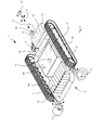
Figure 2 is a perspective view of the robotic apparatus according to the invention in which a portion of external casing has been removed to make the internal parts of the robotic apparatus visible; -
Figures 3 ,4 and 5 are respectively top view, front view and side view of the robotic apparatus without external casing; -
Figures 6 to 11 are further schematic views of the operation of the robotic apparatus; -
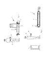
Figures 12 to 14 schematically show an embodiment of the robotic apparatus that includes a navigation device provided with absolute wire encoder transducers. - With reference to the attached Figures, a
robotic apparatus 1 for surface treatment of rotatingrollers 2 is shown, in particular of a train of rotatingrollers 2 for cleaning metal products, in particular metal plates or sheet metal. Therollers 2 to be processed, having longitudinal axes X arranged parallel to one another, are spaced apart from one another in such a manner as to define a train ofrollers 2 that rotate at a peripheral speed Vr, on which, in normal operating conditions of a plant such as a rolling mill or a furnace for thermal treatment, the metal products to be processed advance. - The
robotic apparatus 1 is particularly suitable for removing dirt, metal fragments or other extraneous bodies and surface irregularities from therollers 2, in particular in a rolling mill that has a very narrow inlet section, which is not accessible to humans, or in a furnace used for thermal treatments of metal products, for example annealing, hardening and tempering, tempering, normalizing, stress relieving, etc. As will be clear from the description that follows, therobotic apparatus 1 is able to operate in environments that are not accessible to an operator, for example because of lack of available space. In one embodiment, therobotic apparatus 1 is able to operate in environments at temperatures that are intolerable for humans, for example in environments with temperatures that can reach and exceed 500 °C, as occurs, for example, in furnaces. Therobotic apparatus 1 can even operate for short periods even at a temperature of about 800°C. For this reason, the materials of which theapparatus 1 are made are very resistant to high temperatures. - Surface treatment that is performable by the
robotic apparatus 1, in particular, comprises surface finishing of the rollers that is performed whilst the rollers are rotating, where the term "finishing" refers to any cleaning, smoothing, polishing, grinding, silking, lapping and other finishing operation achieved by abrasive elements, explained better below, such abrasive elements being moved and maintained in contact with the surface to be treated. - The
robotic apparatus 1 comprises a supportingstructure 3 adapted for supporting and/or containing various parts and/or components. Therobotic apparatus 1 comprises first 4a and second 4b advancement means that are drivable in a mutually independent manner. In particular, a pair of trackedelements robotic apparatus 1 advance, which are rotated by respective "brushless" motors. The trackedelements structure 3. Owing to the trackedelements 4 that interact with an extended contact surface, therobotic apparatus 1 is able to move easily on a train ofrollers 2 of a rolling mill or of a furnace for thermal treatment of the workpieces, in particular also whilst therollers 3 are in operation, i.e. rotating. The trackedelements 4 can be made of a material that resists high temperatures, for example steel or another suitable metal, thus enabling therobotic apparatus 1 to access even the hottest zones of the furnace. - The
robotic apparatus 1 comprises abrasive elements 5 (shown in schematic shape) that are configured for removing dirt, detritus, metal fragments, other foreign bodies and surface irregularities from therollers 2. Theabrasive elements 5 are able to provide a surface "finish", in other words they are able to clean, polish, and grind therollers 2 according to particular needs. In particular, theabrasive elements 5 are of rotating type and can comprise brushes, for example provided with blades or flexible portions on which crystalline granules of abrasive material are fixed, which material can be glass or emery. Alternatively or in combination, theabrasive elements 5 can comprise abrasive discs, abrasive rollers, abrasive wheels or other equivalent means. - The
abrasive elements 5, in the embodiment provided by way of non-limited example shown in the attached Figures, comprise twoabrasive brushes 5 that are provided near a front zone of theapparatus 1 and are placed at mutually opposite ends. Theabrasive brushes 5 are connected in an articulated and movable manner with respect to the supportingstructure 3 so as to be able to adjust the position thereof and to be able to regulate the position and the force pressing on therollers 2 according to need. - The
robotic apparatus 1, in one embodiment, is suppliable with electric energy supplied from an external source and it is transmitted to therobotic apparatus 1 by a suitable removable connecting cable. Theabrasive elements 5 can be driven by electricity or by compressed air supplied from an external source of air by means of a suitable air conduit that is connectable to therobotic apparatus 1 and are drivable independently of one another. - The robotic apparatus, in another embodiment, is self-supplied, i.e. it is provided with an incorporated
energy source 6, i.e. an energy source which is, on board, in the robotic apparatus, and which enables the robotic apparatus to move easily without the constraints of an earth connection, so as to be able to reach also the zones that are most difficult to access. In particular, theenergy source 6 comprises a pack of rechargeable batteries, that can be recharged at astation 7 associated with theapparatus 1, which is positionable in a stationary position near a work zone in which theapparatus 1 has to operate. - The
robotic apparatus 1, in one possible embodiment, comprises a cooling and thermalinsulating device 8. The cooling andthermal insulating device 8 is configured for protecting theapparatus 1 from possible overheating, thus enabling theapparatus 1 to operate even in environments that would not be accessible and tolerable to humans because of the high temperature. - The cooling and thermal
insulating device 8 comprises achamber 9 configured for containing acooling substance 10 that is suitable for removing thermal energy from theapparatus 1. Thermal energy can be removed with or without a transitional thermodynamic step, depending on the configuration of the thermal and coolinginsulating device 8, of thecooling substance 10 and of the operating circumstances. Thechamber 9 can be obtained inside acontainer 21 which is removable to enable thecooling substance 10 to be loaded and/or replaced. - In one embodiment, the
cooling substance 10 comprises solid-state carbon dioxide, commonly known as "dry ice", i.e. carbon dioxide cooled to a temperature of about -78 °C or less. The dry ice is loaded into thechamber 9 before cleaning operations of therollers 2 in the furnace. The dry ice, during operation of theapparatus 1, receives thermal energy removed from various zones of theapparatus 1 and undergoes a state change, in particular a process of sublimation from solid state to gaseous state. When the dry ice is substantially finished, i.e. is in gaseous state, it can be replaced with a further quantity of dry ice. - The cooling and
thermal insulating device 8 is provided with forced circulation means 11 arranged for moving cooling fluid inside acooling circuit 12. Thecooling circuit 12 comprises conduits that extend to several zones of theapparatus 1, in particular to the zones that are more sensitive to heat, such as the electrical or electronic parts disclosed below. In one possible embodiment of theapparatus 1, thecooling fluid 12 comprises air and the forced circulation means comprises afan element 11. Thefan element 11, in operation, moves the air inside thecooling circuit 12 making the air interact with the "dry ice" 10 to undergo cooling. The cooled air is made to flow by thefan element 11 along the various conduits of thecooling circuit 12 to reach various zones of theapparatus 1 from which it removes thermal energy, which is subsequently surrendered to thedry ice 10. Instead of air, the operating fluid may comprise an operating cooling liquid, for example water or another liquid that is suitable and compatible with thecooling substance 10. In this case, the forced circulation means 11 comprises a pump that makes the cooling liquid circulate along the conduits of thecooling circuit 12, thus acting on the various zones of theapparatus 1 to be cooled. Thecooling substance 10, in possible alternative embodiments of the apparatus, comprises liquid nitrogen, i.e. nitrogen at about -195°C, or another substance that is suitable for remove thermal energy from theapparatus 1 to protect theapparatus 1 from high temperatures. - The liquid nitrogen is loaded into the
chamber 9 of theapparatus 1, and once the refrigerating capacity has been exhausted it can be replaced with a further quantity of liquid nitrogen. - The cooling and
thermal insulating device 8 is further provided with a temperature-control unit 13, which cooperated with the forced circulation means 11 to control the temperature of theapparatus 1, maintaining the temperature at suitable values. - The cooling and
thermal insulating device 8 further comprises coating panels that are applied to various parts of theapparatus 1 for thermal insulation, in particular at least of the parts that are more sensitive to heat, such as electric/electronic components. - In the apparatus 1 a
control unit 14 is included, powered from the exterior or from the incorporatedenergy source 6, and configured for controlling one or more operating parameters such as: rotation speed of theabrasive elements 5, force of theabrasive elements 5 pressing on therollers 2, advancement direction and speed of the trackedelements 4, and other parameters or functions of theapparatus 1. - The
control unit 14, provided with a calculating device, is provided with anavigation device 15, operationally connected to the trackedelements 4, that enables theapparatus 1 to advance independently along a path P that is desired and can be programmed. - The
navigation device 15 comprises absolute position transducers, such as absolute encoders, for detecting the position of therobotic apparatus 1 with respect to a stationary external reference zone and thus for determining precisely the position of therobotic apparatus 1 on the train ofrotating rollers 2. In particular, the absolute encoders detect the position of therobotic apparatus 1 with respect to astationary module 17 place on the ground in a fixed position, outside therobotic apparatus 1. - The
navigation device 15 includes a processing and driving module that, depending on the position indicated by the absolute transducer means and, taking account of the angular speed or of the peripheral speed Vr of therotating rollers 2, accordingly drives the first 4a and second 4b advancement means in a selective and mutually differentiated manner to generate a desired advancement of therobotic apparatus 1 both in a transverse direction and in a longitudinal direction on the train ofrotating rollers 2, so as to enable theabrasive elements 5 to treat the entire cylindrical surface of each underlyingrotating roller 2 and/or possible furtherupper rollers 2a placed above the robotic apparatus 1 (as shown inFigure 6 ). - In a first embodiment, the
navigation device 15 comprises a detection system that comprises twoabsolute encoders absolute encoders rollers 2, as shown inFigures 12 to 14 , and compriserespective wires robotic apparatus 1. Thewires same attachment zone 32 of therobotic apparatus 1, defining in this manner a triangular configuration that comprises a fixed base and a summit opposite the fixed base and connected to the robot. The triangular configuration thus comprises a base that is kept constant and stationary, and on two sides, defined respectively by thewires robotic apparatus 1. - During operation, if the length of the two side of the triangle is known that vary according to the position of the
robotic apparatus 1, as shown by way of example inFigures 13 and 14 , it is possible to calculate exactly the position of theattachment zone 32, thus of therobotic apparatus 1. The tilt or angular position of therobotic apparatus 1 with respect to the train ofrollers 2 is calculated owing to a software that estimates the tilt both according to the values detected by the twoabsolute wire encoders - In a second embodiment, the
navigation device 15 comprises amovable module 16, placed on theapparatus 1, cooperating with thestationary module 17 placed on the ground in a fixed position, thus outside theapparatus 1. - The stationary module comprises in particular a
transmission module 17 configured for emitting alaser beam 18 along a variable direction in a controlled and programmable manner. Thetransmission module 17 can be incorporated into thestation 7. - The movable module comprises a receiving
module 16 that is suitable for receiving theaforesaid laser beam 18. In one embodiment, the receivingmodule 16 comprises an array of diodes covered by a layer of quartz for protecting from high temperatures and arranged horizontally alongside one another to intercept theaforesaid laser beam 18. Thenavigation device 15 is configured for detecting the zone of incidence of thelaser beam 18 on the array of diodes, in such a manner as to control accordingly the advancement of theapparatus 1. - During operation, the suitably programmed
transmission module 17 emits alaser beam 18 varying in a controlled manner the direction thereof, as indicated by the arrow F inFigures 1 and2 . In particular, thelaser beam 18 is moved in a direction parallel to the longitudinal axes X of therollers 2, in a manner alternating first in one direction and then in the other. - The
navigation device 15, by detecting the variation in the direction of thelaser beam 18 hitting the receivingmodule 16, adjusts the driving speed of each of the trackedelements 4 in an appropriate manner, in such a manner as to rotate theapparatus 1 and orientate it relative to therollers 2. Theapparatus 1, once oriented in the correct manner, advances in such a manner that the receivingmodule 16 follows the movement of thelaser beam 18. This procedure is repeated at each variation in beam direction. - During movement of the
apparatus 1 in a direction parallel to the longitudinal axes X, theabrasive brushes 5 can polish aroller 2 by acting progressively from one end to another of the latter. Thenavigation device 15 calibrates the advancing speed of the trackedelements 4 in such a manner that theapparatus 1, also whilst therollers 2 rotate, is in a stable position near therespective roller 2 subjected to the polishing operation. Once theroller 2 in question is polished thenavigation device 15 temporarily imposes a speed increase on the trackedelements 4 in such a manner that theapparatus 1, by overcoming the dragging effect of therotating rollers 2, advances along a direction A that is orthogonal to the longitudinal axes X, so as to position itself at asubsequent roller 2 to be polished. In other words, theapparatus 1 advances along a path P that comprises, alternately, portions parallel to the longitudinal axes X and portions that are orthogonal to the longitudinal axes X. - The operation of the
robotic apparatus 1 is explained further below. - With reference to the schematic views in
Figures 6 to 11 , an operating method is disclosed for cleaning therotating rollers 2 by therobotic apparatus 1 disclosed above. The description that follows applies both to thelaser navigation device 15 embodiment and to thelaser navigation device 15 embodiment with absolute transducers of the wire type. - In order to start cleaning treatment, the
robotic apparatus 1 is first located on the train ofrollers 2. In this initial step, the first trackedelement 4a and the second trackedelement 4b are driven by thecontrol unit 14 and by thenavigation device 15 in such a manner as o rotate both at the same speed, such a speed having a first value V1 which is equal to the value of the peripheral speed Vr of therollers 2, but in an advancing direction opposite the latter: by so doing, therobotic apparatus 1 is maintained in a stationary position with respect to the earth. This step is schematised inFigures 6 and 7 . In particular, the vectors shown in the left part ofFigure 7 refer respectively to the speed of the rotating rollers 2 (the lower vector) of the first trackedelement 4a and of the second trackedelement 4b (the higher vector). - In a second step, shown in
Figure 8 , the speed of the first trackedelement 4a and of the second trackedelement 4b is varied respectively to a second speed value V2 and to a third speed value V3 to cause a first rotation of therobotic apparatus 1 around a vertical axis. In particular the first trackedelement 4a is driven for a suitable period of time at a speed V2 that is greater in value than the speed Vr of the rollers, in order to determine the rotation of theapparatus 1 by a set angular amount in function of the geometry, dimensions of theapparatus 1 and of therollers 2, which are considered by thecontrol unit 14 and by thenavigation device 15. When the desired angular position of theapparatus 1 in relation to the train ofrotating rollers 2 is reached, the first trackedelement 4a and second trackedelement 4b are both driven at the same speed V4, as shown by the vectors shown in the left part ofFigure 9 . The speed V4 is such as to have a first speed component Vp, parallel to the conveying direction Dc, which is equal in value, but in an opposite direction, to the peripheral speed Vr, and a second speed component Vo orthogonal to the conveying direction Dc, so as to determine a transverse movement of therobotic apparatus 1 along therespective roller 2 from a first end to a second end of the latter. During this step, theabrasive elements 5 are rotated and are in contact with therespective roller 2 so as to remove dirt and/or surface irregularities therefrom along the entire cylindrical surface thereof. - In the meantime, the continuous variation of the absolute position of the
robotic apparatus 1 is detected and controlled by thenavigation device 15 and thecontrol unit 14, which by means of the processing and driving module, act on the trackedelements rotating rollers 2. Reaching the second end of theroller 2 subjected to cleaning is signalled by the absolute transducer means of thenavigation device 15. When this end is reached, the speed of the first 4a and second 4b tracked element is again selectively varied to angularly reposition therobotic apparatus 1 in a longitudinally aligned manner, i.e. parallel to the conveying direction Dc. In order to do this, the speed of the second trackedelement 4b is increased for a set interval of time, as the vectors on the right inFigure 9 show. Subsequently, the speed of the first 4a and second 4b tracked element is further varied and set at the same speed, having a fifth value V5 that is greater than the peripheral speed Vr. In this manner, a longitudinal movement of therobotic apparatus 1 is achieved that is parallel to, but opposite, the conveying direction Dc so as to advance to asubsequent roller 2 to be cleaned, as shown inFigure 10 . - At this point, the speeds of the first 4a and of the second 4b tracked element are respectively taken to the third value V3 and to the second value V2 (already mentioned with reference to the step in
Figure 8 in which, however, they are applied in the opposite direction to the two trackedelements robotic apparatus 1 around the vertical axis is thus determined that is similar to the first rotation ofFigure 8 , but in an opposite direction, as shown inFigure 11 , and, at this point, the first 4a and second 4b tracked elements are both driven at the same speed V4 (similarly to what has been seen for the step shown inFigure 9 ). Theabrasive elements 5 thus intervene again to remove dirt and/or surface irregularities also from thisfurther roller 2. - The aforesaid steps are repeated cyclically until the surface treatment of the entire train of
rotating rollers 2 or possibly of only a desired number ofrotating rollers 2 is completed. - In the above description reference has been made to a possible operating method in which the
robotic apparatus 1 is made to advance progressively in an opposite direction to the conveying direction Dc of therotating rollers 2. Nevertheless, it is also possible to operate therobotic apparatus 1 in the opposite manner, i.e. in such a manner that therobotic apparatus 1 travels progressively along the train of rollers 2., moving concordant with the conveying direction Dc, thus suitably reducing each time the rotation speed of the first 4a and second 4b tracked element to move from one roller to the next adjacent roller. It is further possible to set therobotic apparatus 1 in such a manner as to perform a desired number of cleaning "passes", with theabrasive elements 5, on eachroller 2. - The
apparatus 1, in one embodiment, is also provided with a manual remote control system comprising an incorporated receiving module and aportable control device 19, for example of the type provided with a "touchscreen", that is drivable by anoperator 20 for the remote control of the advancement and operations of theapparatus 1. - The
robotic apparatus 1 further comprises a telediagnosis device for the remote transmission of operating parameters and/or operating conditions of theapparatus 1. In particular, the telediagnosis device communicates remotely the operating conditions of thecooling device 8, and signals if the coolingsubstance 10 has finished or signals an excessive ambient temperature that could damage theapparatus 1. - Sensors can be provided for detecting local parameters at the work zone in which the
apparatus 1 operates, for example for the local temperature value, and cameras for inspecting remotely the surfaces of therollers 2 treated and/or to be treated. - The
robotic apparatus 1 disclosed above is able to operate in zones that are not reachable by an operator, owing to reduced dimensions, as occurs in rolling mills. Further, in the embodiment provided with a cooling and thermal insulatingdevice 8, therobotic apparatus 1 is also able to operate in environments that are not accessible to an operator owing to the temperatures that are intolerable for humans, for example, as already mentioned above, in environments with temperatures that can be comprised between about 350°C and about 500 °C. When therollers 2 to be cleaned are located in zones with temperatures even higher than the range indicated above, therobotic apparatus 1 can already operate when the temperature, following the preliminary switching off of the furnace, is decreased to a value falling within the aforesaid value, without necessarily waiting for this temperature to fall further, as is, on the other hand, necessary with prior art-cleaning systems. Therobotic apparatus 1 thus enables cleaning time to be significantly shortened, the production cycle to be restored more quickly, thus also saving several days, and this enablesoperators 20 to be spared unpleasant and dangerous cleaning operations. - It is possible to configure and dimension the
apparatus 1 in a desired manner in function of the multiple applications to which theapparatus 1 can be intended and versions and/or additions to what has been disclosed above and illustrated in the attached drawings are possible.
Claims (16)
- Robotic apparatus for the surface treatment, in particular cleaning, of a train of rotating rollers (2) for processing metal products, comprising:- abrasive means (5) for removing dirt and/or surface irregularities from said rotating rollers (2);- first (4a) and second (4b) advancement means for advancement on said train of rotating rollers (2), and- a navigation device (15), included in a control unit (14), comprising absolute transducer means for detecting the position of said robotic apparatus (1) with respect to a stationary external reference (17), and thus the position on said train of rotating rollers (2), said navigation device (15) including a processing and driving module that, in function of said position signalled by said absolute transducer means and taking account of the rotation speed of the rotating rollers (2), consequently drives said first (4a) and second (4b) advancement means in a manner that is selective and differentiated from one another to generate a desired advancement of said robotic apparatus (1) both in a transverse direction and in a longitudinal direction on said train of rotating rollers (2), so as to enable said abrasive means (5) to treat the entire cylindrical surface of each said rotating rollers (2) below and/or possible further rollers placed above said robotic apparatus (1).
- Robotic apparatus according to claim 1, wherein said absolute transducer means comprises two absolute encoders (30a, 30b) of the wire type, placed on the ground in a stationary position, that are spaced apart from one another and provided with respective wires (31 a and 31 b), an end of which is connectable to the same attachment zone (32) of said robotic apparatus (1), according to a triangular configuration, said navigation device (15) being configured for determining the position of said robotic apparatus (1) in function of the lengths of the wires (31 a and 31 b), and being further provided with a software that depending on the values detected by the two absolute wire encoders (30a, 30b), and on the values of the rotation speed of said first (4a) and second (4b) advancement means, is able to estimate the angular orientation of said robotic apparatus (1) with respect to said train of rotating rollers (2).
- Robotic apparatus according to claim 1 or 2, wherein said first (4a) and said second (4b) advancement means is arranged on mutually opposite parts, and said control unit (14) includes a calculating device and is configured for driving independently said first (4a) and said second (4b) advancement means to obtain an advancement movement of said robotic apparatus (1) both orthogonally and parallel to longitudinal axes (X) of said rotating rollers (2), said control unit (14) being configured for driving, in response to a position signal supplied by said absolute transducer means, said first (4a) and said second (4b) advancement means at different speeds to rotate said apparatus (1) and orient it in a desired manner with respect to said rotating rollers (2) so as to permit the advancement thereof with a movement component parallel and/or transverse to said longitudinal axes (X).
- Robotic apparatus according to claim 3 as appended to claim 1, wherein said navigation device (15) comprises a stationary module provided with a transmission module (17) configured for emitting a laser beam (18) along a variable direction in a controlled and programmable manner, said navigation device (15) further comprising, on board said robotic apparatus (1), a movable module that includes a receiving module (16) that is suitable for receiving said laser beam (18), said navigation device (15) being configured for following the movement of said laser beam (18) to enable said apparatus (1) to move on said rotating rollers (2) along a programmable desired path (P).
- Robotic apparatus according to claim 4, wherein said receiving module (16) comprises an array of diodes covered by a layer of quartz for protecting from high temperatures and arranged horizontally alongside one another to intercept said laser beam (18), said navigation device (15) being configured for detecting the incidence zone of said laser beam (18) on said array in such a manner as to control the incidence movement of said robotic apparatus (1).
- Robotic apparatus according to any preceding claim, further comprising:- an energy source (6) provided on board said apparatus (1) to power said advancement means (4) and said abrasive means (5), said energy source including rechargeable supply battery means (6), a remote station (7) being provided with arranged for recharging said energy source (6),- a cooling and thermal insulating device (8) configured for protecting the entire apparatus (1) from possible overheating and to enable said apparatus (1) to operate in high-temperature environments that are not accessible to humans, said cooling and thermal insulating device (8) comprising- a chamber (9) configured for containing a cooling substance (10) that is suitable for removing thermal energy from said apparatus (1) so as to enable the apparatus to operate in high-temperature environments such as furnaces for treating metal products, said chamber (9) being obtained in a container (21) which is removable to enable said cooling substance (10) to be loaded and/or replaced,- a cooling circuit (12) distributed along the entire apparatus (1) and suitable for having a cooling fluid flow through it that is arranged for interacting with said cooling substance (10), said cooling circuit comprising conduits (12) that extend to several zones of the apparatus (1), in particular in the zones that are more sensitive to heat, such as electric parts or electronic parts, and- forced circulation means (11) arranged for moving said cooling fluid inside said conduits (12) to reach the various zones of the apparatus (1) from which to remove the thermal energy to be transferred to said cooling substance (10);- thermal panels for thermal insulation of at least parts of said apparatus (1) that are more sensitive to heat.
- Robotic apparatus according to claim 6, wherein said cooling and thermal insulating device (8) comprises temperature-control means (13), cooperating with said forced circulation means (11) for controlling the temperature of said apparatus (1), and wherein said cooling substance (10) is chosen from a group comprising:- solid-state carbon dioxide, intended, during operation, to change from solid state to gaseous state by sublimation during interaction with said cooling fluid;- liquid nitrogen intended, in operation, to change from liquid to gaseous state during interaction with said cooling fluid.
- Apparatus according to claim 6 or 7, wherein said cooling fluid comprises air, and said forced circulation means comprises fan means (11) to make the air interact with said cooling substance (10) and to make the air circulate in said apparatus (1).
- Robotic apparatus according to claim 6 or 7, wherein said cooling fluid comprises a cooling liquid, and said forced circulation means comprises pump means (11) for moving said cooling liquid and making said cooling liquid interact with said cooling substance (10).
- Robotic apparatus according to any preceding claim, wherein said abrasive means comprises a plurality of abrasive elements (5) distributed on one or more sides of said apparatus (1) that are suitable for acting on zones below and/or above said robotic apparatus (1), said abrasive elements (5) being connected in an articulated manner to enable the position of the abrasive elements (5) to be adjusted with respect to said rollers (2) and the force pressing on said rollers (2) by said abrasive elements (5) to be adjusted, wherein said abrasive means (5) is of the rotating type and is chosen from a group comprising: abrasive brushes, abrasive discs, abrasive rollers, abrasive wheels, that are able to perform surface finishing operations.
- Robotic apparatus according to any preceding claim wherein said control unit (14) is configured for controlling one or more operating parameters including: rotation speed of said abrasive means (5), pressing force by said abrasive means (5) on said rotating rollers (2), direction and advancement speed of said first (4a) and second (4b) advancement means.
- Robotic apparatus according to any preceding claim, further comprising a telediagnosis device for remote transmission of operating parameters and/or conditions of said apparatus (1), sensors for detecting local parameters at a work zone in which said apparatus (1) operates and cameras for the remote inspection of the surfaces of said rollers (2), and further comprising an integrated receiving module associated with a remote control (19) that is usable by an operator (20) for navigation and remote control of said apparatus (1).
- Robotic apparatus according to any preceding claim, wherein said advancement means comprises first (4a) and second (4b) tracked means (4, 4a, 4b).
- Method for the surface treatment, in particular cleaning, of a train of rotating rollers (2) by a robotic apparatus (1) according to any preceding claim, wherein said rotating rollers (2) rotate at a peripheral speed (Vr) and are suitable for processing metal products and conveying metal products along a conveying direction (Dc), said method comprising the steps of:a) placing said robotic apparatus (1) on said train of rotating rollers (2) and driving said first (4a) and second (4b) advancement means at the same speed having a first value (V1) equal to the value of said peripheral speed (Vr) but a direction opposite the latter, so as to maintain said robotic apparatus (1) in a stationary position with respect to a fixed external reference,b) selectively varying the speed of said first (4a) and said second (4b) advancement means respectively at a second speed value (V2) and at a third speed value (V3) that are different from one another to cause a first rotation of said robotic apparatus (1) around a vertical axis,c) setting the speed of said first (4a) and said second (4b) advancement means at a same fourth speed value (V4) such as to have a first speed component (Vp), parallel to said conveying direction (Dc), which is equal to said peripheral speed (Vr), and a second speed component (Vo) orthogonally to said conveying direction (Dc), so as to determine transverse movement of said robotic apparatus (1) along the respective roller (2) from a first end to a second end of the latter,d) arranging, during said transverse movement, said abrasive means (5) in rotation and in contact with the respective roller (2) to remove dirt and/or surface irregularities along the entire cylindrical surface thereof,e) progressively detecting the absolute position of said robotic apparatus (1), andf) upon reaching said second end - signalled by said absolute-transducer-means included in said navigation device (15) - selectively varying the speed of said first (4a) and said second (4b) advancement means for angularly repositioning said robotic apparatus (1) in such a manner as to be longitudinally parallel to said conveying direction (Dc),g) further varying the speed of said first (4a) and said second (4b) advancement means at the same speed, having a fifth value (V5) that is different from the value of said peripheral speed (Vr) to determine a longitudinal movement, parallel to said conveying direction (Dc), of said robotic apparatus (1) until said abrasive means (5) is transferred by said first roller to an adjacent second roller,h) selectively varying the speed of said first (4a) and said second (4b) advancement means respectively to said third value (V3) and to said second value (V2) to cause a second rotation, opposite said first rotation, of said robotic apparatus (1) around said vertical axis, and repeating from said step c) onwards, such as to complete the surface treatment of a desired number of rotating rollers (2) or of the entire train of rotating rollers (2).
- Method according to claim 14, wherein selectively controlling the speed of said first (4a) and second (4b) advancement means is provided to automatically compensate for possible variations in the rotation speed of said rotating rollers (2).
- Computer program, comprising software code portions for performing the method according to claim 14 or 15 when said program is run on said calculating device included in said control unit (14).
Applications Claiming Priority (1)
| Application Number | Priority Date | Filing Date | Title |
|---|---|---|---|
| IT001654A ITMI20111654A1 (en) | 2011-09-14 | 2011-09-14 | ROBOTIC DEVICE FOR SURFACE TREATMENT OF ROLLS FOR METALLIC MANUFACTURING |
Publications (3)
| Publication Number | Publication Date |
|---|---|
| EP2570200A2 true EP2570200A2 (en) | 2013-03-20 |
| EP2570200A3 EP2570200A3 (en) | 2014-01-08 |
| EP2570200B1 EP2570200B1 (en) | 2019-01-16 |
Family
ID=44907951
Family Applications (1)
| Application Number | Title | Priority Date | Filing Date |
|---|---|---|---|
| EP12184411.2A Not-in-force EP2570200B1 (en) | 2011-09-14 | 2012-09-14 | Robotic apparatus for the surface treatment, in particular cleaning of rotating rollers |
Country Status (2)
| Country | Link |
|---|---|
| EP (1) | EP2570200B1 (en) |
| IT (1) | ITMI20111654A1 (en) |
Cited By (1)
| Publication number | Priority date | Publication date | Assignee | Title |
|---|---|---|---|---|
| US20220134387A1 (en) * | 2019-03-11 | 2022-05-05 | C.F. Lamiere Di Fantini Claudio Duranti S. Zanni M. & C. S.A.S. | Machine for the removal of waste from work benches of work machines |
Family Cites Families (3)
| Publication number | Priority date | Publication date | Assignee | Title |
|---|---|---|---|---|
| US4475260A (en) * | 1983-01-31 | 1984-10-09 | Beck Richard D | Pipeline servicing tool |
| US7886399B2 (en) * | 2006-08-15 | 2011-02-15 | Umagination Labs, L.P. | Systems and methods for robotic gutter cleaning along an axis of rotation |
| KR20100132891A (en) * | 2009-06-10 | 2010-12-20 | 삼성광주전자 주식회사 | Cleaning device and dust collection method using the same |
-
2011
- 2011-09-14 IT IT001654A patent/ITMI20111654A1/en unknown
-
2012
- 2012-09-14 EP EP12184411.2A patent/EP2570200B1/en not_active Not-in-force
Non-Patent Citations (1)
| Title |
|---|
| None |
Cited By (2)
| Publication number | Priority date | Publication date | Assignee | Title |
|---|---|---|---|---|
| US20220134387A1 (en) * | 2019-03-11 | 2022-05-05 | C.F. Lamiere Di Fantini Claudio Duranti S. Zanni M. & C. S.A.S. | Machine for the removal of waste from work benches of work machines |
| US11919047B2 (en) * | 2019-03-11 | 2024-03-05 | C.F. Lamiere Di Fantini Claudio Durante S. Zanni M.. & C.S.A.S. | Machine for the removal of waste from work benches of work machines |
Also Published As
| Publication number | Publication date |
|---|---|
| ITMI20111654A1 (en) | 2013-03-15 |
| EP2570200B1 (en) | 2019-01-16 |
| EP2570200A3 (en) | 2014-01-08 |
Similar Documents
| Publication | Publication Date | Title |
|---|---|---|
| JP6005871B2 (en) | Method, processing apparatus, and processing system for automatically surface processing of large molded member of wind power generator | |
| JP3044289B2 (en) | Deburring device | |
| CN109551318A (en) | Hub for vehicle wheel polishing system | |
| CN110682169A (en) | Polishing processing equipment and processing method for plated piston rod assembly | |
| EP2570200B1 (en) | Robotic apparatus for the surface treatment, in particular cleaning of rotating rollers | |
| CN105834897A (en) | Intelligent full-automatic circular pipe and rod polishing unit | |
| JP2015208850A (en) | Workpiece processor, and method for automatically controlling dimension of workpiece by the processor | |
| JP6249198B1 (en) | Hand tools | |
| CN103100955A (en) | Rust removal device and rust removal method | |
| CN109227378A (en) | A kind of grinding device and method | |
| CN108381303A (en) | Method for finishing surface | |
| CN105856066A (en) | Intelligent full-automatic polishing unit for rectangular tubes and rod materials | |
| JPH1015798A (en) | Deburring device | |
| CN205085777U (en) | Profile grinder | |
| KR20200051400A (en) | Substrate polishing system | |
| KR101408286B1 (en) | Apparatus for Automatically removing alien substance and scale on precision parts | |
| KR100604140B1 (en) | Square pipe polishing and polishing apparatus and its method | |
| RU206071U1 (en) | DEVICE FOR CLEANING THE EXTERNAL SURFACE OF PIPES | |
| Devine et al. | Spatially-constant material removal control under variable-speed robotic sanding | |
| Li et al. | A new design of flexible constant force grinding head and experimental verification | |
| CN210633451U (en) | CB wire charging tray surface magnesium oxide scale equipment of brushing | |
| WO2022063369A1 (en) | Method and an apparatus for surface treatment of an elongated structure, e.g. a wind turbine blade | |
| RU2493953C2 (en) | Method and device for grinding | |
| US20220297261A1 (en) | Underwater polishing system and underwater polishing method | |
| CN223961067U (en) | Special equipment for mirror polishing of numerical control steel belt |
Legal Events
| Date | Code | Title | Description |
|---|---|---|---|
| PUAI | Public reference made under article 153(3) epc to a published international application that has entered the european phase |
Free format text: ORIGINAL CODE: 0009012 |
|
| 17P | Request for examination filed |
Effective date: 20121030 |
|
| AK | Designated contracting states |
Kind code of ref document: A2 Designated state(s): AL AT BE BG CH CY CZ DE DK EE ES FI FR GB GR HR HU IE IS IT LI LT LU LV MC MK MT NL NO PL PT RO RS SE SI SK SM TR |
|
| AX | Request for extension of the european patent |
Extension state: BA ME |
|
| PUAL | Search report despatched |
Free format text: ORIGINAL CODE: 0009013 |
|
| AK | Designated contracting states |
Kind code of ref document: A3 Designated state(s): AL AT BE BG CH CY CZ DE DK EE ES FI FR GB GR HR HU IE IS IT LI LT LU LV MC MK MT NL NO PL PT RO RS SE SI SK SM TR |
|
| AX | Request for extension of the european patent |
Extension state: BA ME |
|
| RIC1 | Information provided on ipc code assigned before grant |
Ipc: B08B 1/00 20060101AFI20131129BHEP Ipc: B08B 1/04 20060101ALI20131129BHEP |
|
| RBV | Designated contracting states (corrected) |
Designated state(s): AL AT BE BG CH CY CZ DE DK EE ES FI FR GB GR HR HU IE IS IT LI LT LU LV MC MK MT NL NO PL PT RO RS SE SI SK SM TR |
|
| GRAP | Despatch of communication of intention to grant a patent |
Free format text: ORIGINAL CODE: EPIDOSNIGR1 |
|
| STAA | Information on the status of an ep patent application or granted ep patent |
Free format text: STATUS: GRANT OF PATENT IS INTENDED |
|
| INTG | Intention to grant announced |
Effective date: 20180806 |
|
| GRAS | Grant fee paid |
Free format text: ORIGINAL CODE: EPIDOSNIGR3 |
|
| GRAA | (expected) grant |
Free format text: ORIGINAL CODE: 0009210 |
|
| STAA | Information on the status of an ep patent application or granted ep patent |
Free format text: STATUS: THE PATENT HAS BEEN GRANTED |
|
| AK | Designated contracting states |
Kind code of ref document: B1 Designated state(s): AL AT BE BG CH CY CZ DE DK EE ES FI FR GB GR HR HU IE IS IT LI LT LU LV MC MK MT NL NO PL PT RO RS SE SI SK SM TR |
|
| REG | Reference to a national code |
Ref country code: GB Ref legal event code: FG4D |
|
| REG | Reference to a national code |
Ref country code: CH Ref legal event code: EP |
|
| REG | Reference to a national code |
Ref country code: IE Ref legal event code: FG4D |
|
| REG | Reference to a national code |
Ref country code: DE Ref legal event code: R096 Ref document number: 602012055950 Country of ref document: DE |
|
| REG | Reference to a national code |
Ref country code: AT Ref legal event code: REF Ref document number: 1089308 Country of ref document: AT Kind code of ref document: T Effective date: 20190215 |
|
| REG | Reference to a national code |
Ref country code: NL Ref legal event code: MP Effective date: 20190116 |
|
| REG | Reference to a national code |
Ref country code: LT Ref legal event code: MG4D |
|
| PG25 | Lapsed in a contracting state [announced via postgrant information from national office to epo] |
Ref country code: NL Free format text: LAPSE BECAUSE OF FAILURE TO SUBMIT A TRANSLATION OF THE DESCRIPTION OR TO PAY THE FEE WITHIN THE PRESCRIBED TIME-LIMIT Effective date: 20190116 |
|
| REG | Reference to a national code |
Ref country code: AT Ref legal event code: MK05 Ref document number: 1089308 Country of ref document: AT Kind code of ref document: T Effective date: 20190116 |
|
| PG25 | Lapsed in a contracting state [announced via postgrant information from national office to epo] |
Ref country code: ES Free format text: LAPSE BECAUSE OF FAILURE TO SUBMIT A TRANSLATION OF THE DESCRIPTION OR TO PAY THE FEE WITHIN THE PRESCRIBED TIME-LIMIT Effective date: 20190116 Ref country code: PL Free format text: LAPSE BECAUSE OF FAILURE TO SUBMIT A TRANSLATION OF THE DESCRIPTION OR TO PAY THE FEE WITHIN THE PRESCRIBED TIME-LIMIT Effective date: 20190116 Ref country code: LT Free format text: LAPSE BECAUSE OF FAILURE TO SUBMIT A TRANSLATION OF THE DESCRIPTION OR TO PAY THE FEE WITHIN THE PRESCRIBED TIME-LIMIT Effective date: 20190116 Ref country code: FI Free format text: LAPSE BECAUSE OF FAILURE TO SUBMIT A TRANSLATION OF THE DESCRIPTION OR TO PAY THE FEE WITHIN THE PRESCRIBED TIME-LIMIT Effective date: 20190116 Ref country code: SE Free format text: LAPSE BECAUSE OF FAILURE TO SUBMIT A TRANSLATION OF THE DESCRIPTION OR TO PAY THE FEE WITHIN THE PRESCRIBED TIME-LIMIT Effective date: 20190116 Ref country code: NO Free format text: LAPSE BECAUSE OF FAILURE TO SUBMIT A TRANSLATION OF THE DESCRIPTION OR TO PAY THE FEE WITHIN THE PRESCRIBED TIME-LIMIT Effective date: 20190416 Ref country code: PT Free format text: LAPSE BECAUSE OF FAILURE TO SUBMIT A TRANSLATION OF THE DESCRIPTION OR TO PAY THE FEE WITHIN THE PRESCRIBED TIME-LIMIT Effective date: 20190516 |
|
| PG25 | Lapsed in a contracting state [announced via postgrant information from national office to epo] |
Ref country code: BG Free format text: LAPSE BECAUSE OF FAILURE TO SUBMIT A TRANSLATION OF THE DESCRIPTION OR TO PAY THE FEE WITHIN THE PRESCRIBED TIME-LIMIT Effective date: 20190416 Ref country code: RS Free format text: LAPSE BECAUSE OF FAILURE TO SUBMIT A TRANSLATION OF THE DESCRIPTION OR TO PAY THE FEE WITHIN THE PRESCRIBED TIME-LIMIT Effective date: 20190116 Ref country code: IS Free format text: LAPSE BECAUSE OF FAILURE TO SUBMIT A TRANSLATION OF THE DESCRIPTION OR TO PAY THE FEE WITHIN THE PRESCRIBED TIME-LIMIT Effective date: 20190516 Ref country code: LV Free format text: LAPSE BECAUSE OF FAILURE TO SUBMIT A TRANSLATION OF THE DESCRIPTION OR TO PAY THE FEE WITHIN THE PRESCRIBED TIME-LIMIT Effective date: 20190116 Ref country code: HR Free format text: LAPSE BECAUSE OF FAILURE TO SUBMIT A TRANSLATION OF THE DESCRIPTION OR TO PAY THE FEE WITHIN THE PRESCRIBED TIME-LIMIT Effective date: 20190116 Ref country code: GR Free format text: LAPSE BECAUSE OF FAILURE TO SUBMIT A TRANSLATION OF THE DESCRIPTION OR TO PAY THE FEE WITHIN THE PRESCRIBED TIME-LIMIT Effective date: 20190417 |
|
| REG | Reference to a national code |
Ref country code: DE Ref legal event code: R097 Ref document number: 602012055950 Country of ref document: DE |
|
| PG25 | Lapsed in a contracting state [announced via postgrant information from national office to epo] |
Ref country code: SK Free format text: LAPSE BECAUSE OF FAILURE TO SUBMIT A TRANSLATION OF THE DESCRIPTION OR TO PAY THE FEE WITHIN THE PRESCRIBED TIME-LIMIT Effective date: 20190116 Ref country code: RO Free format text: LAPSE BECAUSE OF FAILURE TO SUBMIT A TRANSLATION OF THE DESCRIPTION OR TO PAY THE FEE WITHIN THE PRESCRIBED TIME-LIMIT Effective date: 20190116 Ref country code: IT Free format text: LAPSE BECAUSE OF FAILURE TO SUBMIT A TRANSLATION OF THE DESCRIPTION OR TO PAY THE FEE WITHIN THE PRESCRIBED TIME-LIMIT Effective date: 20190116 Ref country code: EE Free format text: LAPSE BECAUSE OF FAILURE TO SUBMIT A TRANSLATION OF THE DESCRIPTION OR TO PAY THE FEE WITHIN THE PRESCRIBED TIME-LIMIT Effective date: 20190116 Ref country code: CZ Free format text: LAPSE BECAUSE OF FAILURE TO SUBMIT A TRANSLATION OF THE DESCRIPTION OR TO PAY THE FEE WITHIN THE PRESCRIBED TIME-LIMIT Effective date: 20190116 Ref country code: AL Free format text: LAPSE BECAUSE OF FAILURE TO SUBMIT A TRANSLATION OF THE DESCRIPTION OR TO PAY THE FEE WITHIN THE PRESCRIBED TIME-LIMIT Effective date: 20190116 Ref country code: AT Free format text: LAPSE BECAUSE OF FAILURE TO SUBMIT A TRANSLATION OF THE DESCRIPTION OR TO PAY THE FEE WITHIN THE PRESCRIBED TIME-LIMIT Effective date: 20190116 Ref country code: DK Free format text: LAPSE BECAUSE OF FAILURE TO SUBMIT A TRANSLATION OF THE DESCRIPTION OR TO PAY THE FEE WITHIN THE PRESCRIBED TIME-LIMIT Effective date: 20190116 |
|
| PLBE | No opposition filed within time limit |
Free format text: ORIGINAL CODE: 0009261 |
|
| STAA | Information on the status of an ep patent application or granted ep patent |
Free format text: STATUS: NO OPPOSITION FILED WITHIN TIME LIMIT |
|
| PG25 | Lapsed in a contracting state [announced via postgrant information from national office to epo] |
Ref country code: SM Free format text: LAPSE BECAUSE OF FAILURE TO SUBMIT A TRANSLATION OF THE DESCRIPTION OR TO PAY THE FEE WITHIN THE PRESCRIBED TIME-LIMIT Effective date: 20190116 |
|
| 26N | No opposition filed |
Effective date: 20191017 |
|
| PG25 | Lapsed in a contracting state [announced via postgrant information from national office to epo] |
Ref country code: SI Free format text: LAPSE BECAUSE OF FAILURE TO SUBMIT A TRANSLATION OF THE DESCRIPTION OR TO PAY THE FEE WITHIN THE PRESCRIBED TIME-LIMIT Effective date: 20190116 |
|
| PG25 | Lapsed in a contracting state [announced via postgrant information from national office to epo] |
Ref country code: TR Free format text: LAPSE BECAUSE OF FAILURE TO SUBMIT A TRANSLATION OF THE DESCRIPTION OR TO PAY THE FEE WITHIN THE PRESCRIBED TIME-LIMIT Effective date: 20190116 |
|
| REG | Reference to a national code |
Ref country code: DE Ref legal event code: R119 Ref document number: 602012055950 Country of ref document: DE |
|
| PG25 | Lapsed in a contracting state [announced via postgrant information from national office to epo] |
Ref country code: MC Free format text: LAPSE BECAUSE OF FAILURE TO SUBMIT A TRANSLATION OF THE DESCRIPTION OR TO PAY THE FEE WITHIN THE PRESCRIBED TIME-LIMIT Effective date: 20190116 |
|
| REG | Reference to a national code |
Ref country code: CH Ref legal event code: PL |
|
| PG25 | Lapsed in a contracting state [announced via postgrant information from national office to epo] |
Ref country code: LU Free format text: LAPSE BECAUSE OF NON-PAYMENT OF DUE FEES Effective date: 20190914 Ref country code: IE Free format text: LAPSE BECAUSE OF NON-PAYMENT OF DUE FEES Effective date: 20190914 Ref country code: DE Free format text: LAPSE BECAUSE OF NON-PAYMENT OF DUE FEES Effective date: 20200401 Ref country code: CH Free format text: LAPSE BECAUSE OF NON-PAYMENT OF DUE FEES Effective date: 20190930 Ref country code: LI Free format text: LAPSE BECAUSE OF NON-PAYMENT OF DUE FEES Effective date: 20190930 |
|
| REG | Reference to a national code |
Ref country code: BE Ref legal event code: MM Effective date: 20190930 |
|
| PG25 | Lapsed in a contracting state [announced via postgrant information from national office to epo] |
Ref country code: BE Free format text: LAPSE BECAUSE OF NON-PAYMENT OF DUE FEES Effective date: 20190930 |
|
| GBPC | Gb: european patent ceased through non-payment of renewal fee |
Effective date: 20190914 |
|
| PG25 | Lapsed in a contracting state [announced via postgrant information from national office to epo] |
Ref country code: GB Free format text: LAPSE BECAUSE OF NON-PAYMENT OF DUE FEES Effective date: 20190914 Ref country code: FR Free format text: LAPSE BECAUSE OF NON-PAYMENT OF DUE FEES Effective date: 20190930 |
|
| PG25 | Lapsed in a contracting state [announced via postgrant information from national office to epo] |
Ref country code: CY Free format text: LAPSE BECAUSE OF FAILURE TO SUBMIT A TRANSLATION OF THE DESCRIPTION OR TO PAY THE FEE WITHIN THE PRESCRIBED TIME-LIMIT Effective date: 20190116 |
|
| PG25 | Lapsed in a contracting state [announced via postgrant information from national office to epo] |
Ref country code: HU Free format text: LAPSE BECAUSE OF FAILURE TO SUBMIT A TRANSLATION OF THE DESCRIPTION OR TO PAY THE FEE WITHIN THE PRESCRIBED TIME-LIMIT; INVALID AB INITIO Effective date: 20120914 Ref country code: MT Free format text: LAPSE BECAUSE OF FAILURE TO SUBMIT A TRANSLATION OF THE DESCRIPTION OR TO PAY THE FEE WITHIN THE PRESCRIBED TIME-LIMIT Effective date: 20190116 |
|
| PG25 | Lapsed in a contracting state [announced via postgrant information from national office to epo] |
Ref country code: MK Free format text: LAPSE BECAUSE OF FAILURE TO SUBMIT A TRANSLATION OF THE DESCRIPTION OR TO PAY THE FEE WITHIN THE PRESCRIBED TIME-LIMIT Effective date: 20190116 |