EP2569904B1 - Noeud d'anneau, anneau ethernet et procédés de protection contre les boucles dans un anneau ethernet - Google Patents
Noeud d'anneau, anneau ethernet et procédés de protection contre les boucles dans un anneau ethernet Download PDFInfo
- Publication number
- EP2569904B1 EP2569904B1 EP10851483.7A EP10851483A EP2569904B1 EP 2569904 B1 EP2569904 B1 EP 2569904B1 EP 10851483 A EP10851483 A EP 10851483A EP 2569904 B1 EP2569904 B1 EP 2569904B1
- Authority
- EP
- European Patent Office
- Prior art keywords
- ring
- ring node
- node
- ethernet
- erp
- Prior art date
- Legal status (The legal status is an assumption and is not a legal conclusion. Google has not performed a legal analysis and makes no representation as to the accuracy of the status listed.)
- Active
Links
- 238000000034 method Methods 0.000 title claims description 29
- 238000011084 recovery Methods 0.000 claims description 20
- 230000004044 response Effects 0.000 claims description 14
- 238000001914 filtration Methods 0.000 claims description 9
- 230000008859 change Effects 0.000 claims description 5
- 238000004891 communication Methods 0.000 claims description 4
- 238000001514 detection method Methods 0.000 claims description 3
- 230000005641 tunneling Effects 0.000 claims 1
- 230000011664 signaling Effects 0.000 description 11
- 230000000903 blocking effect Effects 0.000 description 9
- 238000010586 diagram Methods 0.000 description 9
- 230000006399 behavior Effects 0.000 description 7
- 101150073388 rpl3 gene Proteins 0.000 description 6
- 230000002776 aggregation Effects 0.000 description 5
- 238000004220 aggregation Methods 0.000 description 5
- 230000009977 dual effect Effects 0.000 description 5
- 238000005516 engineering process Methods 0.000 description 4
- 230000008569 process Effects 0.000 description 4
- 230000008901 benefit Effects 0.000 description 3
- 238000011010 flushing procedure Methods 0.000 description 3
- 230000009471 action Effects 0.000 description 2
- 230000003213 activating effect Effects 0.000 description 2
- 230000001419 dependent effect Effects 0.000 description 2
- 230000000694 effects Effects 0.000 description 2
- 230000032683 aging Effects 0.000 description 1
- 239000000470 constituent Substances 0.000 description 1
- 230000007246 mechanism Effects 0.000 description 1
- 230000004048 modification Effects 0.000 description 1
- 238000012986 modification Methods 0.000 description 1
- 238000005457 optimization Methods 0.000 description 1
- 230000002265 prevention Effects 0.000 description 1
- 230000001960 triggered effect Effects 0.000 description 1
Images


Classifications
-
- H—ELECTRICITY
- H04—ELECTRIC COMMUNICATION TECHNIQUE
- H04L—TRANSMISSION OF DIGITAL INFORMATION, e.g. TELEGRAPHIC COMMUNICATION
- H04L12/00—Data switching networks
- H04L12/28—Data switching networks characterised by path configuration, e.g. LAN [Local Area Networks] or WAN [Wide Area Networks]
- H04L12/42—Loop networks
- H04L12/437—Ring fault isolation or reconfiguration
Definitions
- the invention relates to Ethernet networks, and in particular to a ring node for loop protection in an Ethernet ring.
- the invention further relates to an Ethernet ring, and methods for use in the ring node and in the Ethernet ring.
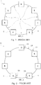
- An Ethernet ring is a collection of ring nodes forming a closed loop whereby each ring node is connected to two adjacent ring nodes via duplex communication links.
- Fig. 1 illustrates an Ethernet ring 1 comprising seven ring nodes A-G connected to each other via duplex communication links 2.
- a loop of data in the Ethernet ring 1 consumes a lot of resources in the Ethernet ring 1 and is therefore an undesired condition. There is therefore a need for protection against loops in the Ethernet ring 1.
- the topology of an Ethernet Ring Protection (ERP) network can be a single Ethernet ring or a collection of interconnected Ethernet rings.
- the G.8032 protocol is designed for Ethernet ring topologies and is developed as a standardized alternative to replace the spanning tree protocol (xSTP). It assumes standard 802.1 Q bridges are used and standard 802.3 MAC frames go around the Ethernet ring. G.8032 Ethernet ring nodes generally support standard FDB MAC learning, forwarding, flush behavior and port blocking/unblocking mechanisms.
- the principle of loop prevention within the Ethernet ring 1 is to block one of the ring links 2, either a pre-determined link or a failed link.
- one of the ring links 2 is designated as a Ring Protection Link (RPL) 3.
- the RPL. 3 blocks Ethernet traffic to avoid traffic looping.
- An RPL 3 blocking is provided by port blocking at both ends of the RPL 3.
- RPL Owner Node 4 e.g. the ring node G, which is also responsible for activating reversion behavior from protected, Manual Switching or Forced Switching conditions.
- the other node is called RPL Node 5, e.g.
- Fig. 2 illustrates an Ethernet Ring Protection (ERP) state.
- ERP Ethernet Ring Protection
- a link failure occurs, for example, a link 24 between ring node D and ring node E.
- Ring node D and ring node E block ports 22, 23 for the failed link 24 and send Ring-APS (R-APS) Signal Failure (SF) messages to indicate the link failure.
- R-APS Ring-APS
- SF Signal Failure
- the SF messages are circulated around the Ethernet ring through a Ring APS channel (not shown).
- the RPL Owner node G and the RPL node A receive this message, they unblock the ports 4A, 5A to the RPL 3.
- Ethernet networks in such ring topologies are not necessarily constructed with the same Ethernet switch hardware for each ring node in the Ethernet ring.
- a Metro Aggregation Network or a Mobile Backhaul Network may be connected to and be configured to aggregate data traffic from subscribers to Metro Core nodes located in the IP core, e.g. in the Ethernet ring.
- This aggregation or backhaul network may be built with different Carrier Ethernet technologies, for example, the Metro Aggregation Network may use pure L2 technologies and the Metro Core nodes may use IP/MPLS technologies.
- the Metro Core nodes may not be configured or capable to run the G.8032 protocol. This causes problems when connecting the Metro Core nodes to an otherwise G.8032 compliant Ethernet ring and results in long overall service restoration times and lost data traffic for ong periods of time.
- Fig. 3 shows schematically an Ethernet ring 31 comprising seven ring nodes A-G connected to each other via duplex communication links.
- the ring nodes A-C and E-G in the Ethernet ring 31 are G.8032 capable nodes, where the ring node G is the RPL Owner Node 4 and the ring node A is the RPL Node 5.
- a non-G.8032 capable node 32 i.e. ring node D, is connected to adjacent G.8032 capable ring nodes C and E and thus forms part of the otherwise G.8032 compliant Ethernet ring 31.
- FIG. 3 In order enable the Ethernet ring protection (ERP) according to the Ethernet ring protection protocol standard G.8032 in the Ethernet ring 31, one interworking alternative arrangement is shown in Fig. 3 , where the adjacent G.8032 capable ring nodes C and E are arranged to tunnel the VLAN that comprises the R-APS messages 33 according to the Ethernet ring protection protocol standard G.8032 through the non-G.8032 capable node D 32.
- ERP Ethernet ring protection
- Ring-APS Ring-APS
- SF Signal Failure
- the non-G.8032 capable node D 32 will not flush its FDB in case of a link failure or recovery event.
- the non-G.8032 capable node D 32 will therefore comprise erroneous FDB entries in its FDB which may take the FDB MAC learning process a long time to correct.
- data traffic can consequently be lost up to a time period corresponding to the FDB MAC address aging time, which is typically in a range of 5 minutes.
- the service layer responsible for the Ethernet data traffic will only be restored with the speed of FDB MAC learning process and is also well dependent on the available bandwidth for the flooding of the data traffic frames. Consequently, the result is long service restoration time of the service layer responsible for the Ethernet data traffic in the Ethernet ring 31 upon a link failure or recovery event. This is particularly critical for sensitive data traffic applications such as, for example, for real-time gaming applications, etc.
- FIG. 4 Another interworking alternative arrangement is shown by the Ethernet ring 41 in Fig. 4 .
- a redundant G.8032 capable ring node 11 42 has been provided in the Ethernet ring 41 to act as an intermediate ring node between the non-G.8032 capable node D 32 and the now fully G.8032 compliant Ethernet ring 41.
- the non-G.8032 capable node D 32 may be connected redundantly via a Link Aggregation Group 43 (LAG) to the G.8032 capable ring node H 42 in the Ethernet ring 41.
- LAG Link Aggregation Group 43
- this interworking alternative arrangement suffers from the disadvantage of having even longer convergence and service restoration times than the previous alternative.
- This arrangement also incur additional implementation costs since it requires two ring nodes instead of one ring node to be deployed in connecting the non-G.8032 capable node D 32 to the Ethernet ring 41, and additional interfaces have to be provided in order to ba able to realize the connection. Furthermore, often the implementation of a LAG 43 does not guarantee full bandwidth utilization since the data traffic distribution algorithms in the ring node do not always lead to a well balanced usage of the single LAG 43 constituents.
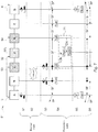
- Fig. 5 shows schematically the interworking of two adjacent G.8032 capable nodes C 53 and E 54 in an Ethernet ring 51 with a non-G.8032 capable node 32 according to an embodiment of the invention.
- the two adjacent G.8032 capable nodes C 53 and E 54 in the Ethernet ring 51 may here be arranged to tunnel the VLAN that comprises the R-APS messages 55 according to the Ethernet ring protection protocol standard G.8032 through the non-G.8032 capable node D 32.
- the two adjacent G.8032 capable nodes C 53 and E 54 may decide in accordance with the ERP protocol standard to perform a flush operation of its filtering database (FDB).
- FDB filtering database
- the two adjacent G.8032 capable nodes C 53 and E 54 may be configured to also send a message 56 to the non-G.8032 capable node D 32.
- the message may be operable to cause the non-G.8032 capable node D 32 to also perform a flush operation of its filtering database (FDB).
- the flush operation in the non-G.8032 capable node D 32 then removes all prior FDB entries from the FDB in the non-G.8032 capable node D 32, except for the FDB entries for the ports on which it received the messages from each of the two adjacent G.8032 capable nodes C 53 and E 54.
- FDB entries filtering database
- the message 56 may be a Spanning Tree Protocol Topology Change Notification (STP TCN).
- the message 56 may be a Rapid Spanning Tree Protocol Topology Change Notification (RSTP TCN).
- the messages 56 may be sent by the two adjacent G.8032 capable nodes C 53 and E 54 in the Ethernet ring 51 using the internal Network-Network-Interface (I-NNI).
- the messages 56 will force the non-G.8032 capable node D 32 to flush its filtering database (FDB) twice, once for each message 56 received from each of the two adjacent G.8032 capable nodes C 53 and E 54 in the Ethernet ring 51.
- FDB filtering database
- the service restoration times of the Ethernet ring 51 may be kept at substantially the same level as in a pure G.8032 capable Ethernet ring wherein all ring nodes A-G performs ERP according to the ERP protocol standard G.8032.
- the two adjacent G.8032 capable nodes C 53 and E 54 may further be configured to react to configuration messages sent by the non-G.8032 capable node D 32 if the non-G.8032 capable node D 32 is running ERP according to another ERP protocol standard. This is described in more detail below in relation to Fig. 8 .
- the two adjacent G.8032 capable nodes C 53 and E 54 may also be configured to correlate the sending of the messages 56 in accordance with these flush optimisations.
- the links between the two adjacent G.8032 capable nodes C 53 and E 54 and the non-G.8032 capable node D 32 may additionally be supervised by Ethernet Continuity Check Messages (CCM) in accordance with the IEEE 802.1ag Connectivity Fault Management standard document.
- CCM Ethernet Continuity Check Messages
- Fig. 6 shows schematically the interworking of two adjacent G.8032 capable nodes C 53 and E 54 in an Ethernet ring 61 with dual non-G.8032 capable nodes 32, i.e. ring nodes D1 and D2, according to another embodiment of the invention.
- the dual non-G.8032 capable nodes D1, D2 32 may be provided in order to have redundancy towards an Metro aggregation or backhaul network 69 being connected to the Ethernet ring 61 through the dual non-G.8032 capable nodes D1, D2 32.
- the two adjacent G.8032 capable nodes C 53 and E 54 in the Ethernet ring 61 may also be arranged to tunnel the VLAN that comprises the R-APS messages 55 according to the Ethernet ring protection protocol standard G.8032 through both of the non-G.8032 capable nodes D1, D2 32.
- the non-G.8032 capable node D 32 is forced to flush its filtering database (FDB) once for each message 56 received from each of the two adjacent G.8032 capable nodes C 53 and E 54 in the Ethernet ring 51.
- the non-G.8032 capable nodes D1 and D2 32 will only receive one message 56 from its adjacent G.8032 capable nodes C 53 and E 54, respectively.
- the nodes D1 and D2 are configured to perform ERP according to STP, one of the nodes D1 and D2 will become the root bridge and the other one a non-root bridge.
- the root node D1 will receive the TCN message 56 from its left adjacent G.8032 capable node C 53 on its left ring port which invokes a flush operation for its right ring ports. This will also result in that the root node D1 sends a TCN message to the non-root node D2.
- the non-root node D2 will thus receive one TCN message from the root node D1 and one TCN message 56 from its right adjacent G.8032 capable node E 54 resulting in a flush operation on both right and left ring ports. Additionally, the non-root node D2 may forward the TCN received from its right adjacent G.8032 capable node E 54 to its root node D1.
- the root node D1 will thus also receive a TCN message on its right ring port which invokes a flush operation for its left ring ports. This ensures that the FDB is flushed on both ring ports in both of the non-G.8032 capable nodes D1 and D2 32.
- Fig. 7 shows a signalling diagram illustrating a method for handling a single link failure in an G.8032 Ethernet ring comprising a non-G.8032 capable node D 32 according to an embodiment of the invention.
- the signalling diagram in Fig. 7 may be compared with the signalling diagram shown in Figure 1V-1/G.8032/Y.1344- Single link failure in the ITU-T G.8032; Ethernet ring protection switching standard document.
- step S1 the Ethernet ring 51 operates in a normal state where no link failure has occured.
- the RPL blocking is provided by R-APS channel or port blocking at both ends of the RPL, i.e. in both the RPL Owner Node G and the RPL Node A.
- step S2 a single link failure occurs between the ring nodes B and C.
- step S3 the ring nodes B and C detects the link failure event and after respecting the holdoff time, blocks the failed R-APS channel or port.
- step S4 the ring nodes B and C periodically send Signal Failure (SF) messages, on both ring ports, as long as the single link failure persists.
- SF Signal Failure
- Fig. 7 this is shown by the filled circles indicating the source of the SF messages.
- the ring nodes B and C may decide to flush its filtering database (FDB).
- the ring node C is an adjacent G.8032 capable ring node C 53 connected to the non-G.8032 capable ring node D 32 it sends, in response to its decision to flush its FDB, a message to the non-G.8032 capable ring node D 32 which is operable to cause the non-G.8032 capable ring node D 32 to also flush its FDB.
- the message may be a STP TCN message as shown in Fig. 7 .
- the non-G.8032 capable ring node D 32 Upon receiving the STP TCN message from the G.8032 capable ring node C 53, the non-G.8032 capable ring node D 32 will flush its FDB on all ports paticipating in the STP domain except for the port where it received the STP TCN message, i.e. a ring port in the direction of the G.8032 capable ring node C 53.
- This is standard behaviour of a STP root bridge as described in IEEE 802.1D MAC Bridges.
- the ring node E being the G.8032 capable ring node E 54 adjacent to a non-G.8032 capable ring node D 32 also sends a message, e.g. a STP TCN message, to the non-G.8032 capable ring node D 32 which is operable to cause the non-G.8032 capable ring node D 32 to flush its FDB.
- a message e.g. a STP TCN message
- the non-G.8032 capable ring node D 32 will flush its FDB on all ports paticipating in the STP domain except for the port where it received the STP TCN message, i.e. a ring port in the direction of the G.8032 capable ring node E 54.
- step S5 the RPL Owner Node G and the RPL Node A unblocks the RPL at both ends and flushes their FDBs.
- step S6 the Ethernet ring 51 operates in a stable protection state where SF messages are periodically sent by the ring nodes B and C, on both ring ports, as long as the single link failure persists.
- the periodical SF messages do not trigger any further action in neither the ring nodes A-B, E-G nor in the adjacent G.8032 capable ring nodes C 53 and E 54.
- the flushing of the FDBs in the adjacent G.8032 capable ring nodes C 53 and E 54 may be triggered by NR RB (No Request, Ring Blocked) messages in case the non-G.8032 capable ring node D 32, for example, is configured to perform ERP according to the STP protocol.
- NR RB No Request, Ring Blocked
- the adjacent G.8032 capable ring nodes C 53 and E 54 may upon receiving the NR RB message and in response to its decision to flush its FDB, send a message, e.g.
- link failure events that may lead to the flushing of the FDBs in the ring nodes A-B, E-G and the adjacent G.8032 capable ring nodes C 53 and E 54 and thus for which the method method described above may be implemented, may include single unidirectional link failures, RPL link failures, etc.
- Fig. 8 shows a signalling diagram illustrating a method for handling a single link failure in an G.8032 Ethernet ring comprising a non-G.8032 capable node D 32 according to an embodiment of the invention.
- the single link failure occurs in between the adjacent G.8032 capable ring node C 53 and the non-G.8032 capable node D 32.
- step S11 the Ethernet ring 51 operates in a normal state where no link failure has occured.
- the RPL blocking is provided by R-APS channel or port blocking at both ends of the RPL, i.e. in both the RPL Owner Node G and the RPL Node A.
- step S12 a single link failure occurs between the adjacent G.8032 capable ring node C 53 and the non-G.8032 capable node D 32.
- the adjacent G.8032 capable ring node C 53 detects the link failure event, e.g. a physical link loss condition, and after respecting the holdoff time, blocks the failed R-APS channel or port.
- the non-G.8032 capable node D 32 also detects the link failure event and after respecting the holdoff time, blocks the failed port.
- the non-G.8032 capable node D 32 is configured to run STP
- the non-G.8032 capable node D 32 assumes that it is the root bridge and will consequently invoke a FDB flush operation for all ports participating in the STP domain except for the port for which it detected the link failure event and send a TCN message to the adjacent G.8032 capable ring node E 54.
- this is standard behaviour of a STP root bridge as described in IEEE 802.1D MAC Bridges.
- the TCN message may be ignored by the adjacent G.8032 capable ring node E 54.
- step S14 the adjacent G.8032 capable ring node C 53 periodically send Signal Failure (SF) messages, on both ring ports, as long as the single link failure persists.
- SF Signal Failure
- Fig. 8 this is shown by the filled circle indicating the source of the SF messages.
- the adjacent G.8032 capable ring node C 53 may decide to flush its filtering database (FDB).
- the ring node C is the adjacent G.8032 capable ring node C 53 connected to the non-G.8032 capable ring node D 32 it will try to send, in response to its decision to flush its FDB, a message to the non-G.8032 capable ring node D 32 which is operable to cause the non-G.8032 capable ring node D 32 to also flush its FDB.
- the message will not reach the non-G.8032 capable ring node D 32.
- the RPL Owner Node G and the RPL Node A unblocks the RPL at both ends and flushes their FDBs.
- step S15 upon receiving the SF message and in response to its decision to flush its FDB, the ring node E being the G.8032 capable ring node E 54 adjacent to the non-G.8032 capable ring node D 32 will also try to send a message, e.g. a STP TCN message, to the non-G.8032 capable ring node D 32 which is operable to cause the non-G.8032 capable ring node D 32 to flush its FDB. Contrary to the previous message, this message will reach the non-G.8032 capable ring node D 32 since there is no link failure between the non-G.8032 capable ring node D 32 and the adjacent G.8032 capable ring node E 54.
- a message e.g. a STP TCN message
- the non-G.8032 capable ring node D 32 Upon receiving the STP TCN message from the adjacent G.8032 capable ring node E 54, the non-G.8032 capable ring node D 32 will flush its FDB on all ports participating in the STP domain except for the port where it received the STP TCN message, i.e. a ring port in the direction of the G.8032 capable ring node E 54. In our case, however, this FDB flush operation will not take effect since the ring port in the direction of the adjacent G.8032 capable ring node C 53 is anyhow not in operation.
- the adjacent G.8032 capable ring node E 54 may keep sending SF messages towards the adjacent G.8032 capable ring node C 53, but the non-G.8032 capable ring node D 32 is not going to be able to pass the SF messages on the adjacent G.8032 capable ring node C 53 due to the single link failure.
- step S16 the Ethernet ring 51 operates in a stable protection state where SF messages are periodically sent by the adjacent G.8032 capable ring node C 53, on both ring ports, as long as the single link failure persists.
- the periodical SF messages do not trigger any further action in neither the ring nodes A-B, E-G nor in the adjacent G.8032 capable ring nodes C 53 and E 54.
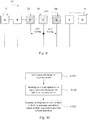
- Fig. 9 shows a signalling diagram illustrating a method for handling initial configuration of a non-G.8032 capable node D 32 in an G.8032 Ethernet ring according to an embodiment of the invention. If, for example, the non-G.8032 capable node D 32 is configured perform ERP according to the STP protocol, the non-G.8032 capable node D 32 will assume that it is placed in an Ethernet ring implementing the STP protocol. This will prompt the following initial behaviour of the MAC bridges in the non-G.8032 capable node D 32.
- configuration BPDU Bridge Protocol Data Unit
- STP Session Transfer Protocol
- the ring node D believes itself as being the root of the tree, and hence the ring node D will set the Root Identifier to the value of its own Bridge Identifier in the configuration BPDU messages it transmits.
- the neighboring ring node compares the received configuration BPDU message with the best BPDU it has. If the neighboring ring node concludes that the new BPDU is better, it will use the sending ring node D as the root and propagate the configuration BPDU messages to other neighboring ring nodes. Otherwise, if the neighboring ring node does not receive any configuration BPDU messages with a better BPDU, it will keep sending configuration BPDU messages assuming itself or the currently best BPDU to be the root bridge.
- the adjacent G.8032 capable ring nodes C 53 and E 54 may therefore be arranged to react on these configuration messages such that the ring node D believes it to be the root bridge an Ethernet ring implementing the STP protocol. As indicated in Fig. 9 , this may be performed by the adjacent G.8032 capable ring nodes C 53 and E 54 by simply stopping or discarding the received STP configuration BDU messages from the ring node D. The stopping or discarding of the received STP configuration BDU messages from the ring node D may be performed by existing message filters in the adjacent G.8032 capable ring nodes C 53 and E 54, e.g.
- this embodiment describes enhanced behaviour in the adjacent G.8032 capable ring nodes C 53 and E 54 to interwork with a non-G.8032 capable node D 32 running STP during initial setup.
- the adjacent G.8032 capable ring nodes C 53 and E 54 additionally needs to react to RSTP BPDU Proposal messages during the root bridge selection phase in the intial setup of RSTP.
- all ring nodes running RSTP are backward compatible with ring nodes running STP, when implemented according to the IEEE 802. 1D MAC Bridges standard document, and the adjacent G.8032 capable ring nodes C 53 and E 54 easily may be modified to respond in accordance with specific implementations, the interworking with RSTP is not described in any further detail herein.
- Fig. 10 shows a flowchart of a method for handling link failure or recovery events in the adjacent G.8032 capable ring nodes C 53 and E 54 according to a further embodiment of the invention.
- the adjacent G.8032 capable ring nodes C 53 and E 54 may be configured to detect a link failure or recovery event.
- the adjacent G.8032 capable ring nodes C 53 and E 54 may decide to perform a flush operation of its FDB in response to the link failure or recovery event detected in step S91.
- the adjacent G.8032 capable ring nodes C 53 and E 54 may be configured to send a message, in response to the decision to perform the flush operation of its FDB, which is operable to cause another network node, e.g. the non-G.8032 capable ring node D 32 or the non-G.8032 capable ring nodes D1 and D2 32, to perform a flush operation of its FDB.
- Ethernet ring protection protocol standards such as, the Ethernet ring protection protocol standards G.8032, STP and RTSP
- G.8032 Ethernet ring protection protocol standards
- STP Secure Transfer Protocol
- RTSP Ethernet ring protection protocol standards
Landscapes
- Engineering & Computer Science (AREA)
- Computer Networks & Wireless Communication (AREA)
- Signal Processing (AREA)
- Small-Scale Networks (AREA)
Claims (15)
- Premier nœud d'anneau (53) agencé pour protéger contre les boucles dans un anneau Ethernet (51, 61) en exécutant une protection d'anneau Ethernet, ERP, conformément à une norme de protocole ERP, le premier nœud d'anneau (53) étant situé directement adjacent à au moins un deuxième nœud d'anneau (32) dans l'anneau Ethernet (51, 61), dans lequel l'au moins un deuxième nœud d'anneau (32) n'est pas configuré pour exécuter une ERP conformément à la même norme de protocole ERP, caractérisé en ce que
le premier nœud d'anneau (53) est configuré pour, lors d'une détection d'un événement de défaillance de liaison ou d'un événement de récupération dans l'anneau Ethernet (51, 61) entraînant une opération de vidage d'une base de données de filtrage, FDB, dans le premier nœud d'anneau (53) conformément à la norme de protocole ERP, envoyer un message à l'au moins un deuxième nœud d'anneau (32), dans lequel le message peut être utilisé pour amener ledit au moins un deuxième nœud d'anneau (32) à exécuter une opération de vidage d'une FDB dans l'au moins un deuxième nœud d'anneau (32). - Premier nœud d'anneau (53) selon la revendication 1, dans lequel le premier nœud d'anneau (53) est configuré pour être relié en communication avec un troisième nœud d'anneau (54) dans l'anneau Ethernet (51, 61) en tunnelisant un VLAN utilisé par la norme de protocole ERP à travers l'au moins un deuxième nœud d'anneau (32), dans lequel ledit troisième nœud d'anneau (54) dans l'anneau Ethernet (51, 61) est configuré pour exécuter une ERP conformément à la même norme de protocole ERP que le premier nœud d'anneau (53).
- Premier nœud d'anneau (53) selon la revendication 1 ou 2, dans lequel l'au moins un deuxième nœud d'anneau (32) dans l'anneau Ethernet (51, 61) est configuré pour exécuter une ERP conformément à une autre norme de protocole ERP.
- Premier nœud d'anneau (53) selon la revendication 3, dans lequel le premier nœud d'anneau (53) est en outre configuré pour réagir à des messages de configuration envoyés par l'au moins un deuxième nœud d'anneau (32) dans l'anneau Ethernet (51, 61) conformément à l'une autre norme de protocole ERP de sorte que des opérations de norme d'ERP, conformément à l'une autre norme de protocole ERP, dans l'au moins un deuxième nœud d'anneau (32) ne sont pas perturbées.
- Premier nœud d'anneau (53) selon l'une quelconque des revendications 1 à 4, dans lequel la norme de protocole ERP pour le premier nœud d'anneau (53) est le protocole de commutation ERP ITU-T G.8032, et l'une autre norme de protocole ERP pour l'au moins un deuxième nœud d'anneau (32) est le protocole Spanning Tree Protocol, STP, ou le protocole Rapid Spanning Tree Protocol, RSTP.
- Premier nœud d'anneau (53) selon la revendication 5, dans lequel, si l'une autre norme de protocole ERP est le RSTP, le premier nœud d'anneau (53) est en outre configuré pour répondre aux messages de configuration envoyés par l'au moins un deuxième nœud d'anneau (32) dans l'anneau Ethernet (51, 61) lors de la configuration initiale du RSTP.
- Premier nœud d'anneau (53) selon l'une quelconque des revendications 5 à 6, dans lequel le message comprend une notification de changement de topologie de Spanning Tree Protocol, STP TCN, ou une notification de changement de topologie de Rapid Spanning Tree Protocol, RSTP TCN, et dans lequel le message est envoyé par le premier nœud d'anneau (53) à l'au moins un deuxième nœud d'anneau (32) à l'aide d'une interface réseau interne-réseau, I-NNI.
- Premier nœud d'anneau (53) selon l'une quelconque des revendications 1 à 7, dans lequel les événements de défaillance de liaison ou les événements de récupération se produisant entre le premier nœud d'anneau (53) et l'au moins un deuxième nœud d'anneau (32) dans l'anneau Ethernet (51, 61) sont également supervisés par des messages de contrôle de continuité, CCM, Ethernet conformément au protocole de la norme de gestion des défauts de connectivité IEEE 802.1 ag.
- Procédé à utiliser dans un premier nœud d'anneau (53) pour protéger contre les boucles dans un anneau Ethernet (51, 61) en exécutant une protection d'anneau Ethernet, ERP, conformément à une norme de protocole ERP, le premier nœud d'anneau (53) étant situé directement adjacent à au moins un deuxième nœud d'anneau (32) dans l'anneau Ethernet (51, 61), dans lequel l'au moins un deuxième nœud d'anneau (32) n'est pas configuré pour exécuter une ERP conformément à la même norme de protocole ERP, le procédé comprenant les étapes de :détection d'un événement de défaillance de liaison ou d'un événement de récupération dans l'anneau Ethernet (51, 61) conformément à la norme de protocole ERP ;décision d'exécuter une opération de vidage d'une base de données de filtrage, FDB, dans le premier nœud d'anneau (53) en réponse à l'événement de défaillance de liaison détecté ou à l'événement de récupération détecté, ledit procédé étant caractérisé en ce qu'il comprend en outre l'étape :
en réponse à la décision d'exécuter l'opération de vidage, d'envoi d'un message à l'au moins un deuxième nœud d'anneau (32), dans lequel le message peut être utilisé pour amener ledit au moins un deuxième nœud d'anneau (32) à exécuter une opération de vidage d'une FDB dans l'au moins un deuxième nœud d'anneau (32) . - Procédé selon la revendication 9, comprenant en outre l'étape de :
réaction, dans lequel l'au moins un deuxième nœud d'anneau (32) dans l'anneau Ethernet (51, 61) est configuré pour exécuter une ERP conformément à une autre norme de protocole ERP, à des messages de configuration envoyés par l'au moins un deuxième nœud d'anneau (32) dans l'anneau Ethernet (51, 61) de sorte que des opérations de norme d'ERP, conformément à l'une autre norme de protocole ERP, dans l'au moins un deuxième nœud d'anneau (32) ne sont pas perturbées. - Procédé selon la revendication 10, comprenant en outre l'étape de :
réponse, si l'une autre norme de protocole ERP est Rapid Spanning Tree Protocol, RSTP, aux messages de configuration envoyés par l'au moins un deuxième nœud d'anneau (32) dans l'anneau Ethernet (51, 61) lors de la configuration initiale du RSTP. - Anneau Ethernet (51, 61) comprenant un premier nœud d'anneau (53) selon la revendication 1 et au moins un troisième nœud d'anneau (54) agencé pour protéger contre lesdites boucles dans l'anneau Ethernet (51, 61) en exécutant ladite ERP conformément à ladite norme de protocole ERP, caractérisé en ce que
l'au moins un troisième nœud d'anneau (54) qui est situé directement adjacent à l'au moins un deuxième nœud d'anneau (32) dans l'anneau Ethernet (51, 61) est configuré pour, lors de la détection de l'événement de défaillance de liaison ou de l'événement de récupération dans l'anneau Ethernet (51, 61) entraînant une opération de vidage de FDB dans l'au moins un troisième nœud d'anneau (54) conformément à la norme de protocole ERP, envoyer un message audit au moins un deuxième nœud d'anneau (32), dans lequel le message envoyé par l'au moins un troisième nœud d'anneau (54) peut être utilisé pour amener ledit au moins un deuxième nœud d'anneau (32) à exécuter une opération de vidage de la FDB dans l'au moins un deuxième nœud d'anneau (32). - Anneau Ethernet (51,61) selon la revendication 12, dans lequel, si l'au moins un deuxième nœud d'anneau (32) est configuré pour exécuter une ERP conformément à une autre norme de protocole ERP et comprend plusieurs nœuds d'anneau (D1, D2), des mesures de résilience pour une connectivité entre les plusieurs nœuds d'anneau (D1, D2) sont prévues.
- Réseau de communications à large bande comprenant un premier nœud d'anneau (53) selon la revendication 1, et/ou un anneau Ethernet (51, 61) selon la revendication 12.
- Procédé, à utiliser dans un anneau Ethernet (51, 61) selon la revendication 9, l'anneau Ethernet (51, 61) comprenant en outre au moins un troisième nœud d'anneau (54) agencé pour protéger contre lesdites boucles dans l'anneau Ethernet (51, 61) en exécutant ladite ERP conformément à ladite norme de protocole ERP, le procédé comprenant les étapes de :
décision d'exécuter une opération de vidage d'une FDB dans l'au moins un troisième nœud d'anneau (54) en réponse à l'événement de défaillance de liaison détecté ou à l'événement de récupération détecté, le procédé étant caractérisé en ce qu'il comprend en outre l'étape :
en réponse à la décision d'exécuter l'opération de vidage de ladite FDB dans ledit au moins un troisième nœud d'anneau (54), d'envoi d'un message, depuis l'au moins un troisième nœud d'anneau (54) qui est situé directement adjacent à l'au moins un deuxième nœud d'anneau (32) dans l'anneau Ethernet (51, 61) à l'au moins un deuxième nœud d'anneau (32), dans lequel le message envoyé par ledit au moins un troisième nœud d'anneau (54) peut être utilisé pour amener ledit au moins un deuxième nœud d'anneau (32) à exécuter une opération de vidage de ladite FDB dans l'au moins un deuxième nœud d'anneau (32).
Applications Claiming Priority (1)
| Application Number | Priority Date | Filing Date | Title |
|---|---|---|---|
| PCT/SE2010/050511 WO2011142697A1 (fr) | 2010-05-10 | 2010-05-10 | Nœud d'anneau, anneau ethernet et procédés de protection contre les boucles dans un anneau ethernet |
Publications (3)
| Publication Number | Publication Date |
|---|---|
| EP2569904A1 EP2569904A1 (fr) | 2013-03-20 |
| EP2569904A4 EP2569904A4 (fr) | 2015-06-10 |
| EP2569904B1 true EP2569904B1 (fr) | 2020-12-02 |
Family
ID=44914574
Family Applications (1)
| Application Number | Title | Priority Date | Filing Date |
|---|---|---|---|
| EP10851483.7A Active EP2569904B1 (fr) | 2010-05-10 | 2010-05-10 | Noeud d'anneau, anneau ethernet et procédés de protection contre les boucles dans un anneau ethernet |
Country Status (3)
| Country | Link |
|---|---|
| US (1) | US9276767B2 (fr) |
| EP (1) | EP2569904B1 (fr) |
| WO (1) | WO2011142697A1 (fr) |
Families Citing this family (23)
| Publication number | Priority date | Publication date | Assignee | Title |
|---|---|---|---|---|
| CN101815107B (zh) * | 2010-05-13 | 2013-10-09 | 华为技术有限公司 | 一种以太环网中管理地址的方法、系统以及设备 |
| TWI427972B (zh) * | 2010-10-26 | 2014-02-21 | Accton Technology Corp | 建立路徑資訊之網路裝置及其方法 |
| US9491041B2 (en) * | 2011-03-07 | 2016-11-08 | Tejas Networks Limited | Ethernet chain protection switching |
| KR101318156B1 (ko) * | 2012-03-26 | 2013-10-15 | 주식회사 다산네트웍스 | 이더넷 링 네트워크에서의 보호 절체 방법 |
| TW201412058A (zh) * | 2012-09-07 | 2014-03-16 | Etherwan Systems Inc | 環狀網路之備援系統與環狀網路之備援方法 |
| US9264348B2 (en) * | 2012-09-14 | 2016-02-16 | Juniper Networks, Inc. | Avoiding data traffic loss in an ethernet ring multihomed, in an active-standby manner, to a virtual private LAN service transport network |
| CN102932172A (zh) * | 2012-10-23 | 2013-02-13 | 华为技术有限公司 | 一种检测以太网环故障节点的方法、设备和系统 |
| WO2014199471A1 (fr) * | 2013-06-12 | 2014-12-18 | 三菱電機株式会社 | Système et dispositif de communication, et procédé de protection |
| JP6295137B2 (ja) * | 2014-04-28 | 2018-03-14 | APRESIA Systems株式会社 | 中継システムおよびスイッチ装置 |
| CN106161078B (zh) | 2015-04-27 | 2019-06-21 | 华为技术有限公司 | 一种以太网环保护倒换方法及节点 |
| US9843495B2 (en) * | 2015-08-26 | 2017-12-12 | Fujitsu Limited | Seamless migration from rapid spanning tree protocol to ethernet ring protection switching protocol |
| US10474654B2 (en) * | 2015-08-26 | 2019-11-12 | Storagecraft Technology Corporation | Structural data transfer over a network |
| US10659251B2 (en) | 2016-02-26 | 2020-05-19 | Hewlett Packard Enterprise Development Lp | Ring protection network division |
| US10193765B2 (en) * | 2016-05-19 | 2019-01-29 | Ciena Corporation | Protection switching systems and methods in a packet network based on signal degrade |
| US10135715B2 (en) * | 2016-08-25 | 2018-11-20 | Fujitsu Limited | Buffer flush optimization in Ethernet ring protection networks |
| US9923731B1 (en) * | 2016-09-12 | 2018-03-20 | Fujitsu Limited | Seamless migration from multiple spanning tree protocol to ethernet ring protection switching protocol |
| US9929878B1 (en) * | 2016-09-15 | 2018-03-27 | Fujitsu Limited | Auto detection and prevention of loop, segmentation and traffic outage in a G.8032 ring network |
| US10382301B2 (en) * | 2016-11-14 | 2019-08-13 | Alcatel Lucent | Efficiently calculating per service impact of ethernet ring status changes |
| JP6922442B2 (ja) * | 2017-06-02 | 2021-08-18 | 富士通株式会社 | 伝送システム、伝送装置及びループ防止方法 |
| US11025537B2 (en) * | 2017-12-04 | 2021-06-01 | Is5 Communications, Inc. | Multiple RSTP domain separation |
| US11108623B2 (en) | 2019-01-25 | 2021-08-31 | Hewlett Packard Enterprise Development Lp | Rapid owner selection |
| US10756813B1 (en) * | 2019-05-03 | 2020-08-25 | Cisco Technology, Inc. | Broadband subscriber switchover in a ring network |
| US11212217B2 (en) * | 2019-10-30 | 2021-12-28 | Dell Products L.P. | Spanning tree enabled link aggregation system |
Citations (1)
| Publication number | Priority date | Publication date | Assignee | Title |
|---|---|---|---|---|
| US20100287405A1 (en) * | 2009-05-08 | 2010-11-11 | Tellabs Operations, Inc. | Method and apparatus for internetworking networks |
Family Cites Families (9)
| Publication number | Priority date | Publication date | Assignee | Title |
|---|---|---|---|---|
| GB2171880A (en) * | 1985-03-01 | 1986-09-03 | Stc Plc | Local area network |
| GB0501131D0 (en) * | 2005-01-20 | 2005-02-23 | Siemens Ag | A method of operating a node in a network |
| CN101232427A (zh) * | 2007-01-23 | 2008-07-30 | 华为技术有限公司 | 一种以太网环保护方法及装置 |
| US8804534B2 (en) | 2007-05-19 | 2014-08-12 | Cisco Technology, Inc. | Interworking between MPLS/IP and Ethernet OAM mechanisms |
| US20090016214A1 (en) * | 2007-07-12 | 2009-01-15 | Allied Telesis Holdings K.K. | Method and system for network recovery from multiple link failures |
| US8305938B2 (en) * | 2007-12-31 | 2012-11-06 | Ciena Corporation | Interworking an ethernet ring network with a spanning tree controlled ethernet network |
| US8018841B2 (en) * | 2007-12-31 | 2011-09-13 | Ciena Corporation | Interworking an ethernet ring network and an ethernet network with traffic engineered trunks |
| US8625410B2 (en) * | 2009-05-11 | 2014-01-07 | Ciena Corporation | Dual homed E-spring protection for network domain interworking |
| US8355348B1 (en) * | 2009-08-17 | 2013-01-15 | Calix, Inc. | Joining multiple spanning tree networks across ring network |
-
2010
- 2010-05-10 EP EP10851483.7A patent/EP2569904B1/fr active Active
- 2010-05-10 WO PCT/SE2010/050511 patent/WO2011142697A1/fr active Application Filing
- 2010-05-10 US US13/696,426 patent/US9276767B2/en not_active Expired - Fee Related
Patent Citations (1)
| Publication number | Priority date | Publication date | Assignee | Title |
|---|---|---|---|---|
| US20100287405A1 (en) * | 2009-05-08 | 2010-11-11 | Tellabs Operations, Inc. | Method and apparatus for internetworking networks |
Non-Patent Citations (1)
| Title |
|---|
| DOOJEONG LEE ET AL: "Efficient ethernet multi-ring protection system", DESIGN OF RELIABLE COMMUNICATION NETWORKS, 2009. DRCN 2009. 7TH INTERNATIONAL WORKSHOP ON, IEEE, PISCATAWAY, NJ, USA, 25 October 2009 (2009-10-25), pages 305 - 311, XP031570689, ISBN: 978-1-4244-5047-3 * |
Also Published As
| Publication number | Publication date |
|---|---|
| EP2569904A4 (fr) | 2015-06-10 |
| EP2569904A1 (fr) | 2013-03-20 |
| WO2011142697A1 (fr) | 2011-11-17 |
| US20130064071A1 (en) | 2013-03-14 |
| US9276767B2 (en) | 2016-03-01 |
Similar Documents
| Publication | Publication Date | Title |
|---|---|---|
| EP2569904B1 (fr) | Noeud d'anneau, anneau ethernet et procédés de protection contre les boucles dans un anneau ethernet | |
| EP2117176B1 (fr) | Procédé de mise en oeuvre de réseau en boucle intercroisé avec une topologie arbitraire, noeud et réseau en boucle intercroisé | |
| US9042216B2 (en) | Loop prevention mechanism for ethernet ring protection | |
| EP1575221B1 (fr) | Commutation de protection automatique pour ethernet | |
| US20090207726A1 (en) | System and method for network recovery from multiple link failures | |
| EP2204947A1 (fr) | Procédé et dispositif de n ud de détection de défaillance et de convergence ethernet | |
| US7752338B2 (en) | Ring topology discovery | |
| US7606240B1 (en) | Ethernet automatic protection switching | |
| US9705701B2 (en) | Method for protecting an Ethernet ring from a superloop going through the Ethernet ring | |
| WO2009082825A1 (fr) | Interfonctionnement d'un réseau en anneau ethernet et d'un réseau ethernet comportant des circuits de liaison conçus en fonction du trafic | |
| EP2207307B1 (fr) | Procédé de traitement de panne du port esclave du noeud maître dans un système de réseau ethernet en anneau | |
| WO2012162946A1 (fr) | Procédé et système de traitement de message | |
| WO2010031295A1 (fr) | Procédé de contrôle pour reprise après une panne ethernet | |
| CN102238067B (zh) | 一种快速环网保护协议环上的切换方法和装置 | |
| WO2012079313A1 (fr) | Procédé de protection de liaison et système associé | |
| CN101883038A (zh) | Eaps环网保护倒换的方法及eaps环网中的主节点 | |
| EP2553881B1 (fr) | Procédé de protection contre les superboucles dans un anneau ethernet | |
| EP2448190B1 (fr) | Procédé de protection locale de tunnel ethernet et noeud de partage de sections de travail de domaine de protection | |
| JP5004758B2 (ja) | レイヤ2ネットワークおよびネットワーク接続装置 | |
| JP2011223172A (ja) | リング型ネットワークシステム、通信装置および障害検出方法 | |
| CN101815021A (zh) | 一种以太网保护中协议通道的实现方法 | |
| CN101883000B (zh) | 一种网络保护方法及网络保护架构 | |
| KR101235376B1 (ko) | 이더넷 링 보호 절체 방법 및 시스템 | |
| JP2005341128A (ja) | レイヤ2伝送装置およびレイヤ2伝送装置の制御方法 | |
| JP2015119448A (ja) | 伝送装置 |
Legal Events
| Date | Code | Title | Description |
|---|---|---|---|
| PUAI | Public reference made under article 153(3) epc to a published international application that has entered the european phase |
Free format text: ORIGINAL CODE: 0009012 |
|
| 17P | Request for examination filed |
Effective date: 20121203 |
|
| AK | Designated contracting states |
Kind code of ref document: A1 Designated state(s): AL AT BE BG CH CY CZ DE DK EE ES FI FR GB GR HR HU IE IS IT LI LT LU LV MC MK MT NL NO PL PT RO SE SI SK SM TR |
|
| DAX | Request for extension of the european patent (deleted) | ||
| RA4 | Supplementary search report drawn up and despatched (corrected) |
Effective date: 20150511 |
|
| RIC1 | Information provided on ipc code assigned before grant |
Ipc: H04L 12/437 20060101AFI20150505BHEP Ipc: H04L 12/46 20060101ALI20150505BHEP Ipc: H04L 12/28 20060101ALI20150505BHEP |
|
| STAA | Information on the status of an ep patent application or granted ep patent |
Free format text: STATUS: EXAMINATION IS IN PROGRESS |
|
| 17Q | First examination report despatched |
Effective date: 20190131 |
|
| GRAP | Despatch of communication of intention to grant a patent |
Free format text: ORIGINAL CODE: EPIDOSNIGR1 |
|
| STAA | Information on the status of an ep patent application or granted ep patent |
Free format text: STATUS: GRANT OF PATENT IS INTENDED |
|
| INTG | Intention to grant announced |
Effective date: 20200915 |
|
| GRAS | Grant fee paid |
Free format text: ORIGINAL CODE: EPIDOSNIGR3 |
|
| GRAA | (expected) grant |
Free format text: ORIGINAL CODE: 0009210 |
|
| STAA | Information on the status of an ep patent application or granted ep patent |
Free format text: STATUS: THE PATENT HAS BEEN GRANTED |
|
| AK | Designated contracting states |
Kind code of ref document: B1 Designated state(s): AL AT BE BG CH CY CZ DE DK EE ES FI FR GB GR HR HU IE IS IT LI LT LU LV MC MK MT NL NO PL PT RO SE SI SK SM TR |
|
| REG | Reference to a national code |
Ref country code: GB Ref legal event code: FG4D |
|
| REG | Reference to a national code |
Ref country code: AT Ref legal event code: REF Ref document number: 1342140 Country of ref document: AT Kind code of ref document: T Effective date: 20201215 Ref country code: CH Ref legal event code: EP |
|
| REG | Reference to a national code |
Ref country code: IE Ref legal event code: FG4D |
|
| REG | Reference to a national code |
Ref country code: DE Ref legal event code: R096 Ref document number: 602010066075 Country of ref document: DE |
|
| PG25 | Lapsed in a contracting state [announced via postgrant information from national office to epo] |
Ref country code: GR Free format text: LAPSE BECAUSE OF FAILURE TO SUBMIT A TRANSLATION OF THE DESCRIPTION OR TO PAY THE FEE WITHIN THE PRESCRIBED TIME-LIMIT Effective date: 20210303 Ref country code: NO Free format text: LAPSE BECAUSE OF FAILURE TO SUBMIT A TRANSLATION OF THE DESCRIPTION OR TO PAY THE FEE WITHIN THE PRESCRIBED TIME-LIMIT Effective date: 20210302 Ref country code: FI Free format text: LAPSE BECAUSE OF FAILURE TO SUBMIT A TRANSLATION OF THE DESCRIPTION OR TO PAY THE FEE WITHIN THE PRESCRIBED TIME-LIMIT Effective date: 20201202 |
|
| REG | Reference to a national code |
Ref country code: NL Ref legal event code: MP Effective date: 20201202 |
|
| REG | Reference to a national code |
Ref country code: AT Ref legal event code: MK05 Ref document number: 1342140 Country of ref document: AT Kind code of ref document: T Effective date: 20201202 |
|
| PG25 | Lapsed in a contracting state [announced via postgrant information from national office to epo] |
Ref country code: SE Free format text: LAPSE BECAUSE OF FAILURE TO SUBMIT A TRANSLATION OF THE DESCRIPTION OR TO PAY THE FEE WITHIN THE PRESCRIBED TIME-LIMIT Effective date: 20201202 Ref country code: PL Free format text: LAPSE BECAUSE OF FAILURE TO SUBMIT A TRANSLATION OF THE DESCRIPTION OR TO PAY THE FEE WITHIN THE PRESCRIBED TIME-LIMIT Effective date: 20201202 Ref country code: LV Free format text: LAPSE BECAUSE OF FAILURE TO SUBMIT A TRANSLATION OF THE DESCRIPTION OR TO PAY THE FEE WITHIN THE PRESCRIBED TIME-LIMIT Effective date: 20201202 Ref country code: BG Free format text: LAPSE BECAUSE OF FAILURE TO SUBMIT A TRANSLATION OF THE DESCRIPTION OR TO PAY THE FEE WITHIN THE PRESCRIBED TIME-LIMIT Effective date: 20210302 |
|
| PG25 | Lapsed in a contracting state [announced via postgrant information from national office to epo] |
Ref country code: NL Free format text: LAPSE BECAUSE OF FAILURE TO SUBMIT A TRANSLATION OF THE DESCRIPTION OR TO PAY THE FEE WITHIN THE PRESCRIBED TIME-LIMIT Effective date: 20201202 Ref country code: HR Free format text: LAPSE BECAUSE OF FAILURE TO SUBMIT A TRANSLATION OF THE DESCRIPTION OR TO PAY THE FEE WITHIN THE PRESCRIBED TIME-LIMIT Effective date: 20201202 |
|
| REG | Reference to a national code |
Ref country code: LT Ref legal event code: MG9D |
|
| PG25 | Lapsed in a contracting state [announced via postgrant information from national office to epo] |
Ref country code: EE Free format text: LAPSE BECAUSE OF FAILURE TO SUBMIT A TRANSLATION OF THE DESCRIPTION OR TO PAY THE FEE WITHIN THE PRESCRIBED TIME-LIMIT Effective date: 20201202 Ref country code: CZ Free format text: LAPSE BECAUSE OF FAILURE TO SUBMIT A TRANSLATION OF THE DESCRIPTION OR TO PAY THE FEE WITHIN THE PRESCRIBED TIME-LIMIT Effective date: 20201202 Ref country code: SM Free format text: LAPSE BECAUSE OF FAILURE TO SUBMIT A TRANSLATION OF THE DESCRIPTION OR TO PAY THE FEE WITHIN THE PRESCRIBED TIME-LIMIT Effective date: 20201202 Ref country code: SK Free format text: LAPSE BECAUSE OF FAILURE TO SUBMIT A TRANSLATION OF THE DESCRIPTION OR TO PAY THE FEE WITHIN THE PRESCRIBED TIME-LIMIT Effective date: 20201202 Ref country code: RO Free format text: LAPSE BECAUSE OF FAILURE TO SUBMIT A TRANSLATION OF THE DESCRIPTION OR TO PAY THE FEE WITHIN THE PRESCRIBED TIME-LIMIT Effective date: 20201202 Ref country code: PT Free format text: LAPSE BECAUSE OF FAILURE TO SUBMIT A TRANSLATION OF THE DESCRIPTION OR TO PAY THE FEE WITHIN THE PRESCRIBED TIME-LIMIT Effective date: 20210405 Ref country code: LT Free format text: LAPSE BECAUSE OF FAILURE TO SUBMIT A TRANSLATION OF THE DESCRIPTION OR TO PAY THE FEE WITHIN THE PRESCRIBED TIME-LIMIT Effective date: 20201202 |
|
| PG25 | Lapsed in a contracting state [announced via postgrant information from national office to epo] |
Ref country code: AT Free format text: LAPSE BECAUSE OF FAILURE TO SUBMIT A TRANSLATION OF THE DESCRIPTION OR TO PAY THE FEE WITHIN THE PRESCRIBED TIME-LIMIT Effective date: 20201202 |
|
| REG | Reference to a national code |
Ref country code: DE Ref legal event code: R097 Ref document number: 602010066075 Country of ref document: DE |
|
| PG25 | Lapsed in a contracting state [announced via postgrant information from national office to epo] |
Ref country code: IS Free format text: LAPSE BECAUSE OF FAILURE TO SUBMIT A TRANSLATION OF THE DESCRIPTION OR TO PAY THE FEE WITHIN THE PRESCRIBED TIME-LIMIT Effective date: 20210402 |
|
| PLBE | No opposition filed within time limit |
Free format text: ORIGINAL CODE: 0009261 |
|
| STAA | Information on the status of an ep patent application or granted ep patent |
Free format text: STATUS: NO OPPOSITION FILED WITHIN TIME LIMIT |
|
| PG25 | Lapsed in a contracting state [announced via postgrant information from national office to epo] |
Ref country code: AL Free format text: LAPSE BECAUSE OF FAILURE TO SUBMIT A TRANSLATION OF THE DESCRIPTION OR TO PAY THE FEE WITHIN THE PRESCRIBED TIME-LIMIT Effective date: 20201202 Ref country code: IT Free format text: LAPSE BECAUSE OF FAILURE TO SUBMIT A TRANSLATION OF THE DESCRIPTION OR TO PAY THE FEE WITHIN THE PRESCRIBED TIME-LIMIT Effective date: 20201202 |
|
| 26N | No opposition filed |
Effective date: 20210903 |
|
| PG25 | Lapsed in a contracting state [announced via postgrant information from national office to epo] |
Ref country code: SI Free format text: LAPSE BECAUSE OF FAILURE TO SUBMIT A TRANSLATION OF THE DESCRIPTION OR TO PAY THE FEE WITHIN THE PRESCRIBED TIME-LIMIT Effective date: 20201202 Ref country code: DK Free format text: LAPSE BECAUSE OF FAILURE TO SUBMIT A TRANSLATION OF THE DESCRIPTION OR TO PAY THE FEE WITHIN THE PRESCRIBED TIME-LIMIT Effective date: 20201202 Ref country code: ES Free format text: LAPSE BECAUSE OF FAILURE TO SUBMIT A TRANSLATION OF THE DESCRIPTION OR TO PAY THE FEE WITHIN THE PRESCRIBED TIME-LIMIT Effective date: 20201202 |
|
| REG | Reference to a national code |
Ref country code: CH Ref legal event code: PL |
|
| PG25 | Lapsed in a contracting state [announced via postgrant information from national office to epo] |
Ref country code: CH Free format text: LAPSE BECAUSE OF NON-PAYMENT OF DUE FEES Effective date: 20210531 Ref country code: LU Free format text: LAPSE BECAUSE OF NON-PAYMENT OF DUE FEES Effective date: 20210510 Ref country code: LI Free format text: LAPSE BECAUSE OF NON-PAYMENT OF DUE FEES Effective date: 20210531 Ref country code: MC Free format text: LAPSE BECAUSE OF FAILURE TO SUBMIT A TRANSLATION OF THE DESCRIPTION OR TO PAY THE FEE WITHIN THE PRESCRIBED TIME-LIMIT Effective date: 20201202 |
|
| REG | Reference to a national code |
Ref country code: BE Ref legal event code: MM Effective date: 20210531 |
|
| PG25 | Lapsed in a contracting state [announced via postgrant information from national office to epo] |
Ref country code: IE Free format text: LAPSE BECAUSE OF NON-PAYMENT OF DUE FEES Effective date: 20210510 |
|
| PG25 | Lapsed in a contracting state [announced via postgrant information from national office to epo] |
Ref country code: IS Free format text: LAPSE BECAUSE OF FAILURE TO SUBMIT A TRANSLATION OF THE DESCRIPTION OR TO PAY THE FEE WITHIN THE PRESCRIBED TIME-LIMIT Effective date: 20210402 Ref country code: FR Free format text: LAPSE BECAUSE OF NON-PAYMENT OF DUE FEES Effective date: 20210531 |
|
| PG25 | Lapsed in a contracting state [announced via postgrant information from national office to epo] |
Ref country code: BE Free format text: LAPSE BECAUSE OF NON-PAYMENT OF DUE FEES Effective date: 20210531 |
|
| PGFP | Annual fee paid to national office [announced via postgrant information from national office to epo] |
Ref country code: GB Payment date: 20220527 Year of fee payment: 13 Ref country code: DE Payment date: 20220527 Year of fee payment: 13 |
|
| PG25 | Lapsed in a contracting state [announced via postgrant information from national office to epo] |
Ref country code: HU Free format text: LAPSE BECAUSE OF FAILURE TO SUBMIT A TRANSLATION OF THE DESCRIPTION OR TO PAY THE FEE WITHIN THE PRESCRIBED TIME-LIMIT; INVALID AB INITIO Effective date: 20100510 Ref country code: CY Free format text: LAPSE BECAUSE OF FAILURE TO SUBMIT A TRANSLATION OF THE DESCRIPTION OR TO PAY THE FEE WITHIN THE PRESCRIBED TIME-LIMIT Effective date: 20201202 |
|
| REG | Reference to a national code |
Ref country code: DE Ref legal event code: R119 Ref document number: 602010066075 Country of ref document: DE |
|
| GBPC | Gb: european patent ceased through non-payment of renewal fee |
Effective date: 20230510 |
|
| PG25 | Lapsed in a contracting state [announced via postgrant information from national office to epo] |
Ref country code: MK Free format text: LAPSE BECAUSE OF FAILURE TO SUBMIT A TRANSLATION OF THE DESCRIPTION OR TO PAY THE FEE WITHIN THE PRESCRIBED TIME-LIMIT Effective date: 20201202 Ref country code: DE Free format text: LAPSE BECAUSE OF NON-PAYMENT OF DUE FEES Effective date: 20231201 Ref country code: GB Free format text: LAPSE BECAUSE OF NON-PAYMENT OF DUE FEES Effective date: 20230510 |
|
| PG25 | Lapsed in a contracting state [announced via postgrant information from national office to epo] |
Ref country code: TR Free format text: LAPSE BECAUSE OF FAILURE TO SUBMIT A TRANSLATION OF THE DESCRIPTION OR TO PAY THE FEE WITHIN THE PRESCRIBED TIME-LIMIT Effective date: 20201202 |