EP2568676A2 - Pre-coding method, pre-decoding method, transmitter and mobile terminal based on interference alignment - Google Patents
Pre-coding method, pre-decoding method, transmitter and mobile terminal based on interference alignment Download PDFInfo
- Publication number
- EP2568676A2 EP2568676A2 EP12183117A EP12183117A EP2568676A2 EP 2568676 A2 EP2568676 A2 EP 2568676A2 EP 12183117 A EP12183117 A EP 12183117A EP 12183117 A EP12183117 A EP 12183117A EP 2568676 A2 EP2568676 A2 EP 2568676A2
- Authority
- EP
- European Patent Office
- Prior art keywords
- cell
- matrix
- transmitter
- user
- decoding
- Prior art date
- Legal status (The legal status is an assumption and is not a legal conclusion. Google has not performed a legal analysis and makes no representation as to the accuracy of the status listed.)
- Granted
Links
Images

Classifications
-
- H—ELECTRICITY
- H04—ELECTRIC COMMUNICATION TECHNIQUE
- H04L—TRANSMISSION OF DIGITAL INFORMATION, e.g. TELEGRAPHIC COMMUNICATION
- H04L25/00—Baseband systems
- H04L25/02—Details ; arrangements for supplying electrical power along data transmission lines
- H04L25/03—Shaping networks in transmitter or receiver, e.g. adaptive shaping networks
- H04L25/03006—Arrangements for removing intersymbol interference
- H04L25/03343—Arrangements at the transmitter end
-
- H—ELECTRICITY
- H04—ELECTRIC COMMUNICATION TECHNIQUE
- H04B—TRANSMISSION
- H04B7/00—Radio transmission systems, i.e. using radiation field
- H04B7/02—Diversity systems; Multi-antenna system, i.e. transmission or reception using multiple antennas
- H04B7/022—Site diversity; Macro-diversity
- H04B7/024—Co-operative use of antennas of several sites, e.g. in co-ordinated multipoint or co-operative multiple-input multiple-output [MIMO] systems
-
- H—ELECTRICITY
- H04—ELECTRIC COMMUNICATION TECHNIQUE
- H04B—TRANSMISSION
- H04B7/00—Radio transmission systems, i.e. using radiation field
- H04B7/02—Diversity systems; Multi-antenna system, i.e. transmission or reception using multiple antennas
- H04B7/04—Diversity systems; Multi-antenna system, i.e. transmission or reception using multiple antennas using two or more spaced independent antennas
- H04B7/0413—MIMO systems
- H04B7/0452—Multi-user MIMO systems
-
- H—ELECTRICITY
- H04—ELECTRIC COMMUNICATION TECHNIQUE
- H04B—TRANSMISSION
- H04B7/00—Radio transmission systems, i.e. using radiation field
- H04B7/02—Diversity systems; Multi-antenna system, i.e. transmission or reception using multiple antennas
- H04B7/04—Diversity systems; Multi-antenna system, i.e. transmission or reception using multiple antennas using two or more spaced independent antennas
- H04B7/0413—MIMO systems
- H04B7/0456—Selection of precoding matrices or codebooks, e.g. using matrices antenna weighting
-
- H—ELECTRICITY
- H04—ELECTRIC COMMUNICATION TECHNIQUE
- H04L—TRANSMISSION OF DIGITAL INFORMATION, e.g. TELEGRAPHIC COMMUNICATION
- H04L25/00—Baseband systems
- H04L25/02—Details ; arrangements for supplying electrical power along data transmission lines
- H04L25/03—Shaping networks in transmitter or receiver, e.g. adaptive shaping networks
- H04L25/03891—Spatial equalizers
- H04L25/03898—Spatial equalizers codebook-based design
Definitions
- the present invention relates to a multi-cell coordinated communication technology in a wireless communication system, and more particularly to a pre-coding method, a pre-decoding method, a transmitter and a mobile terminal in the multi-cell coordinated communication system using an interference alignment scheme.
- co-channel interference In a wireless mobile cellular network, if neighboring cells work at the same frequency range, user terminals at the border of a cell will be strongly interfered by the neighboring cells. This kind of interference is called co-channel interference. This kind of co-channel interference may influence the communication quality, such as the transmission data-rate and reliability, of user terminals at the border of the cell.
- a frequency-division multiplexing is adopted, i.e. neighboring cells use different sub-bands for transmission.
- the interference between neighboring cells may be avoided.
- resources for transmitting useful signals are reduced and therefore frequency spectrum utilization efficiency is reduced.
- new cellular system such as Long Term Evolution (LTE) network
- LTE Long Term Evolution
- interference alignment methods have been proposed. According to this method, not only the interference between cells is suppressed, but also more resources are reserved for transmitting useful signals. Based on these advantages, a more spectrum-efficient wireless transmission may be obtained by using the interference alignment method.
- a basic idea of the interference alignment is to divide a signal space into a desired signal sub-space and an interference signal sub-space and then to have all interference signals into the interference signal sub-space so as to effectively suppress the interference between cells.
- Non-patent document 1 C. Suh et.al., "Downlink Interference Alignment” GlobeCOM 2010
- Non-patent document 2 W. Shin et. al. "On the Design of Interference Alignment Scheme for Two-Cell MIMO Interfering Broadcast Channels" IEEE Trans. on Wireless Comm.2011 ) propose two multi-cell multi-user linear pre-coding and pre-decoding methods based on the interference alignment.
- researches on the interference alignment are focused on theoretical phase and not in practice.
- An object of the present invention is to provide a pre-coding method, a pre-decoding method, a transmitter and a mobile terminal in a multi-cell coordinated communication system based on an interference alignment scheme.
- a pre-coding method based on an interference alignment scheme comprises steps of: computing an antenna mapping matrix using the downlink channel state information matrices of the channels between the transmitter and the terminals within the cell covered by the transmitter, wherein the antenna mapping matrix is used for antenna mapping for the current transmitter so as to perform an interference alignment scheme; computing a multi-cell pre-coding matrix for the transmitter and a multi-cell decoding matrix for each terminal within the coordinating cell using the downlink channel state information matrices of the channels between the transmitter and the terminals within the coordinating cell and using the antenna mapping matrix; computing a single cell multi-user pre-coding matrix for the current transmitter using the downlink channel state information matrices of the channels between the transmitter and the terminals within the cell covered by the transmitter, the antenna mapping matrix, the multi-cell pre-decoding matrix, and the multi-cell decoding matrices for the terminals within the cell covered by the current transmitter, the multi-cell decoding matrices are received from the transmitter
- a transmitter comprising: an antenna mapping matrix computing unit, for computing an antenna mapping matrix using the downlink channel state information matrices of the channels between the transmitter and the terminals within the cell covered by the transmitter, wherein the antenna mapping matrix is used for antenna mapping for the current transmitter so as to perform an interference alignment scheme; a multi-cell pre-coding matrix computing unit, for computing a multi-cell pre-coding matrix for the transmitter and a multi-cell decoding matrix for each terminal within the coordinating cell using the downlink channel state information matrices of the channels between the transmitter and the terminals within the coordinating cell and using the antenna mapping matrix; ; a single cell multi-user pre-coding matrix computing unit, for computing a single cell multi-user pre-coding matrix for the current transmitter using the downlink channel state information matrices of the channels between the transmitter and the terminals within the cell covered by the transmitter, the antenna mapping matrix, the multi-cell pre-decoding matrix, and the multi-cell decoding matrices for the
- a pre-decoding method based on an interference alignment scheme comprises steps of: receiving a multi-cell decoding matrix from the transmitter of the serving cell by a mobile terminal; decoding a downlink user data using the multi-cell decoding matrix; estimating a single cell multi-user equivalent channel using a downlink signal from the transmitter and the multi-cell decoding matrix obtained from the previous step, and computing a single cell multi-user decoding matrix according to the resultant single cell multi-user equivalent channel; and detecting downlink data using the single cell multi-user decoding matrix obtained from the previous step.
- a mobile terminal comprises: a multi-cell decoding unit, for receiving a multi-cell decoding matrix from the transmitter of the serving cell by a mobile terminal and decoding a downlink user data using the multi-cell decoding matrix; ; a channel estimation unit, for estimating a single cell multi-user equivalent channel using a downlink signal from the transmitter and the multi-cell decoding matrix obtained from the previous step, and computing a single cell multi-user decoding matrix according to the resultant single cell multi-user equivalent channel; and a multi-user decoding unit, for and detecting downlink data using the single cell multi-user decoding matrix obtained from the previous step.
- a specified system may be transformed into an equivalent system which may use an interference alignment scheme by antenna mapping, i.e., a system which cannot use the interference alignment scheme directly may be transformed into a system which can use the interference alignment scheme directly.
- the interference suppression between cells and the interference management inside cells are two separate processes, in which different linear pre-coding and pre-decoding methods may be used. Therefore, a variety of implementing schemes may be obtained and different schemes have different performances and complexities, which are suitable for different communication environments.
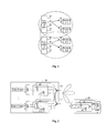
- Fig. 1 shows a scenario in which a method according to an embodiment of the invention may be applied
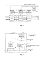
- Fig. 2 is a schematic diagram showing a transmitter and a mobile terminal based on a pre-coding and pre-decoding method
- Fig. 3 is block diagram showing a structure of a transmitter according to an embodiment of the invention.
- Fig. 4 is a block diagram showing a structure of a mobile terminal according to an embodiment of the invention.
- Fig. 5 is a flow chart showing the pre-coding and pre-decoding method based on an interference alignment scheme according to an embodiment of the invention.
- Fig. 1 shows a scenario in which a method according to an embodiment of the invention may be applied.
- two transmitters of two neighboring cells a transmitter of cell 1 and a transmitter of cell 2
- they are connected by cable (connection shown by a dashed line) so as to perform limited information exchange.
- This information exchange is limited to system status information or control information but without user data, i.e. data transmitted to users are only stored locally in the transmitter of the cell in which the user terminal locates.
- the cell corresponding to the transmitter may be an area covered by a single base station or a sector covered by a certain transmitter of the base station.
- Each transmitter serves multiple users in the cell.
- the transmitter in cell 1 serves terminal (1, 1) and terminal (1, 2) and the transmitter in cell 2 serves terminal (2, 1) and terminal (2, 2). Since the two cells work at the same frequency range, the co-channel interference may occur in the neighboring cell 1 and cell 2.
- the transmitter in cell 1 and the transmitter in cell 2 work together to suppress the co-channel interference between cells by the limited signaling exchange. Since there is cooperation (coordination) between cells and at the same time each cell serves multiple users, the system is called as a multi-cell multi-user system.
- the method according to an embodiment of the invention relates to a multi-cell coordinating communication system based on a multi-antenna linear pre-coding and/or decoding, in which pre-coding matrices and decoding matrices are obtained based on an interference alignment scheme.
- Fig. 2 is a schematic diagram showing a transmitter and a mobile terminal based on a pre-coding and pre-decoding method.
- data of user 1 and data of user 2 are weighted-added and then mapped to a transmitting antenna array.
- a matrix (or vector) constituted by weight coefficients at the transmitter is called a pre-coding matrix (or vector).
- signals received at different antennas are weighted-overlapped to obtain a useful signal.
- a matrix (or vector) constituted by weighted coefficients at the receiver is called as a decoding matrix (or vector).
- a higher frequency spectrum utilization efficiency of the multi-cell coordinating communication system can be obtained by optimizing the pre-coding matrix (or vector) and the decoding matrix (or vector) so as to ensure a high quality data transmission of the user.
- An input and output relation of the multi-cell multi-user downlink MIMO system adopting the linear pre-coding and decoding method may be represented by the following formula.
- H i , i , k DL is a downlink channel matrix between transmitter i and user terminal k in cell i ;
- H j , i , k DL is a downlink channel matrix between
- An input and output relation of the multi-cell multi-user uplink MIMO system adopting the linear pre-coding and decoding method may be represented by the following formula.
- H i , j , l UL is a uplink channel matrix between transmitter i and user terminal l in cell j ; H i , j ,
- Fig. 3 is block diagram showing a structure of a transmitter according to an embodiment of the invention.
- a transmitter 20 comprises a channel estimation unit 21.
- the channel estimation unit 21 is configured for:
- the transmitter 20 further comprises an antenna mapping matrix computing unit 22, which is configured for computing an antenna mapping matrix based on the downlink channel state information matrices of the channels between the transmitter 20 and the terminals within the cell covered by the transmitter 20.
- the transmitter 20 further comprises a multi-cell pre-coding matrix computing unit 23, which is configured for computing a multi-cell pre-coding matrix for the transmitter 20 and a multi-cell decoding matrix for each terminal within a coordinating cell using the downlink channel state information matrices of the channels between the transmitter 20 and the terminals within the range of the coordinating cell and using the antenna mapping matrix.
- the transmitter 20 further comprises a single cell multi-user pre-coding matrix computing unit 24, which is configured for computing an equivalent single cell multi-user channel matrix and thus a single cell multi-user pre-coding matrix for the transmitter 20 according to the downlink channel state information matrices of the channels between the transmitter 20 and the terminals within a cell covered by the transmitter 20, the antenna mapping matrix of the transmitter 20 and the multi-cell pre-coding matrix as well as the multi-cell decoding matrices for the terminals of the current transmitter 20, the multi-cell decoding matrices are received from the transmitter of the coordinating cell.
- a single cell multi-user pre-coding matrix computing unit 24 is configured for computing an equivalent single cell multi-user channel matrix and thus a single cell multi-user pre-coding matrix for the transmitter 20 according to the downlink channel state information matrices of the channels between the transmitter 20 and the terminals within a cell covered by the transmitter 20, the antenna mapping matrix of the transmitter 20 and the multi-cell pre-coding matrix as well as the multi-cell decoding matrices for the terminals
- the single cell multi-user pre-coding matrix computing unit 24 computes the single cell multi-user pre-coding matrix according to the equivalent single cell multi-user channel matrix and a noise power measurement value received from the terminal within the cell covered by the transmitter 20.
- the transmitter 20 further comprises a single cell pre-coding unit 25, which is configured for performing a single cell pre-coding by using the single cell multi-user pre-coding matrix, i.e. for performing a linear overlapping of data of multiple users in the cell.
- the transmitter 20 further comprises a multi-cell pre-coding unit 26, which is configured for performing a multi-cell pre-coding on the data after the single cell pre-coding by using the multi-cell pre-coding matrix so as to realize the interference suppression between cells.
- a multi-cell pre-coding unit 26 which is configured for performing a multi-cell pre-coding on the data after the single cell pre-coding by using the multi-cell pre-coding matrix so as to realize the interference suppression between cells.
- the transmitter 20 further comprises an antenna mapping unit 27, which is configured for mapping the linear overlapped user data after the multi-cell pre-coding to a transmitting antenna array.
- Fig. 4 is a block diagram showing a structure of a mobile terminal according to an embodiment of the invention.
- an interference and noise measurement unit 31 at one side of the mobile terminal 30 measures an interference and noise value using the downlink reference signals and inputs the interference and noise value to a noise level mapping unit 32.
- the noise level mapping unit 32 maps the interference and noise value to a corresponding noise level and feeds it back to the transmitter 20.
- a decomposing unit 33 decomposes the downlink demodulated reference signal and the downlink data and then a channel estimation unit 35 performs a channel estimation based on the downlink signal to obtain a downlink channel matrix.
- a multi-cell decoding unit 34 receives from the transmitter in its own cell the multi-cell decoding matrix transmitted from the transmitter in the coordinating cell, it decodes the downlink user data by using the multi-cell decoding matrix so as to eliminate the interference between cells.
- the channel estimation unit 35 estimates the single cell multi-user equivalent channel according to the multi-cell decoding matrix and the downlink signal and computes the single cell multi-user decoding matrix according to the single cell multi-user equivalent channel. Then, a multi-user decoding unit 36 performs a MIMO detection on the downlink data by using the single cell multi-user decoding matrix and then outputs a data flow.
- a specified system may be transformed into an equivalent system which may use the interference alignment method by antenna mapping, i.e., a system which cannot use the interference alignment method directly may be transformed into a system which can use the interference alignment method directly.
- the interference suppression between cells and the interference management inside cells are two separate processes, in which different linear pre-coding and decoding methods may be used. Therefore, a lot of implementing schemes may be obtained and different schemes have different performances and complexities, which are suitable for different communication environments.
- the antenna mapping matrix computing unit 22 computes the antenna mapping matrix and the antenna mapping unit 27 transforms the specified system into a system which may use the interference alignment scheme by using the antenna mapping matrix.
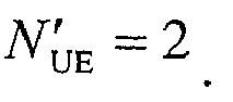
- the number of the antennas at the transmitter in the specified system is N BS and the number of the antennas at the terminal side in the specified system is N UE .
- An antenna configuration for the system which may use the interference alignment method should satisfy the following conditions: the number of the antennas at the transmitter in the specified system is larger than or equal to the number of the antennas at the transmitter in the equivalent system while the number of the antennas at the terminal side in the specified system is equal to the number of the antennas at the terminal side in the equivalent system, i.e.
- N BS ⁇ N ' BS and N UE N UE ⁇ , in which N BS ⁇ represents the number of the antennas at the transmitter in the equivalent system and N UE ⁇ represents the number of the antennas at the terminal side in the equivalent system.
- the system is transformed by a linear mapping, i.e. by finding a N BS ⁇ ⁇ N BS antenna mapping matrix. Therefore, when performing the antenna mapping, the N BS data flows are linearly pre-coded using the antenna mapping matrix. Taking the system shown in Fig. 1 as an example, the antenna mapping matrix should be a 3*4 matrix.
- P pre_AM 1 is used to represent the antenna mapping matrix of the transmitter in cell 1.
- a N BS ⁇ ⁇ N BS matrix may be generated randomly as the antenna mapping matrix P pre_AM 1 ⁇ P pre_AM 1 is only used for antenna mapping and any N BS ⁇ ⁇ N BS matrix may also realize antenna mapping. It is less complex and more convenient to randomly generate the antenna mapping matrix.
- N BS ⁇ columns are selected from the unitary matrix V and the N BS ⁇ columns correspond to N BS ⁇ maximum singular values.
- the antenna mapping matrix P pre_AM 1 according to the embodiment is constituted by the N BS ⁇ column vectors.
- the antenna mapping matrix P pre_AM 2 of the transmitter in cell 2 may also be obtained.
- the multi-cell pre-coding for a transmitter should be designed together with the multi-cell decoding for the user terminals within the coordinating cell and the principle for the design is interference alignment. Operations of the multi-cell pre-coding matrix computing unit 23 are described with reference to an example (taking the transmitter in cell 1 in Fig. 1 as an example).
- the equivalent interference channel matrix and the decoding matrices for two terminals in cell 2 are obtained by constituting a linear equation using the downlink channel matrices of the channels between transmitter 1 and the two terminals within cell 2 and the antenna mapping matrix P pre_AM 1 of cell 1.
- the multi-cell pre-coding matrix is computed according to the orthogonality between the equivalent interference channel matrix and the multi-cell pre-coding matrix. For example, the following linear equation is constituted by the downlink channel matrices and the antenna mapping matrix P pre_AM 1 .
- H 1,2,1 is the downlink channel between the transmitter of cell 1 to terminal 1 (i.e. terminal (2, 1)) of cell 2;
- H 1,2,2 is the downlink channel between the transmitter of cell 1 and terminal 2 (i.e.
- P pre_AM 1 is the antenna mapping matrix of the transmitter of cell 1
- h IA 1 is the equivalent interference channel matrix of the transmitter in cell 1
- g 2,1 is the multi-cell decoding matrix for terminal (2, 1)
- g 2 , 2 is the multi-cell decoding matrix for terminal (2, 2);
- I 3 ⁇ 3 is a unit diagonal matrix having 3 lines and 3 columns; 0 3 ⁇ 2 is an all zero matrix having 3 lines and 2 columns; 0 6 ⁇ 1 is an all zero column vector having 6 lines and 1 column.
- the decoding matrices g 2,1 and g 2,2 may be obtained by solving equation (4) and these two decoding matrices are the decoding matrices for the two users (i.e. terminal (2, 1) and terminal (2, 2)) in cell 2.
- interference signals from the transmitter of cell 1 to two terminals in cell 2 are aligned to the same direction, i.e. the direction indicated by vector h IA 1 . If the direction in which the transmitter of cell 1 transmitting data to a terminal in cell 1 is orthogonal to the direction indicated by vector h IA 1 , no interference signal from the transmitter of cell 1 to terminals in cell 2 will be produced. Equation (5) is defined for this orthogonality. Combining equation (4) and (5), the interference between cells may be eliminated. At the same time, since interference signals are substantially aligned to the same direction, more directions for useful signals may be left.
- P pre_IA 2 , g 1,1 and g 1,2 may be obtained by a same operation at the transmitter of cell 2, i.e. the multi-cell pre-coding matrix of cell 2, the multi-cell decoding matrix for terminal (1, 1) and the multi-cell decoding matrix for terminal (1, 2) may be obtained.
- the equivalent interference channel matrix and the decoding matrices for two terminals in cell 1 are obtained by constituting a linear equation using the downlink channel matrices of the channels between transmitter 1 and the two terminals within cell 2 and the antenna mapping matrix P pre_IA 2 of the transmitter of cell 2.
- the multi-cell pre-coding matrix is computed according to the orthogonality between the equivalent interference channel matrix and the multi-cell pre-coding matrix.
- the following linear equation is constituted by the downlink channel matrices and the antenna mapping matrix P pre_AM 2 .
- H 2,1,1 is the downlink channel from the transmitter of cell 2 to terminal 1 (i.e., terminal (1, 1)) within cell 1
- H 2,1,2 is the downlink channel from the transmitter of cell 2 to terminal 2 (i.e., terminal (1, 2)) within cell 1
- P pre_AM 2 is the antenna mapping matrix of the transmitter of cell 2
- h IA 2 is the equivalent interference channel matrix of the transmitter in cell 2
- g 1,1 is the multi-cell decoding matrix for terminal (1, 1)
- g 1,2 is the multi-cell decoding matrix for terminal (1, 2);
- I 3 ⁇ 3 is a unit diagonal matrix having 3 lines and 3 columns; 0 3 ⁇ 2 is an all zero matrix having 3 lines and
- the decoding matrices g 1,1 and g 1 , 2 may be obtained by solving equation (4') and these two decoding matrices are the decoding matrices for the two terminals (i.e. terminal (1, 1) and terminal (1, 2)) in cell 1.
- equation (6') interference signals from the transmitter of cell 2 to two terminals in cell 1 are aligned to the same direction, i.e. the direction indicated by vector h IA 2 . If the direction in which the transmitter of cell 2 transmitting data to a terminal in cell 2 is orthogonal to the direction indicated by vector h IA 2 , no interference signal from the transmitter of cell 2 to terminals in cell 1 will be produced. Equation (5') is defined for this orthogonality. Combining equation (4') and (5'), the interference between cells may be eliminated. At the same time, since interference signals are substantially aligned to the same direction, more directions for useful signals may be left.
- an operation of the single cell multi-user pre-coding matrix computing unit 24 may be described with reference to the following example (taking the transmitter of cell 1 as an example).
- a equivalent multi-user multi-antenna system matrix is constituted by the downlink channel matrices between the transmitter in cell 1 and the terminal (1,1) and (1, 2), the resultant antenna mapping matrix P pre_AM 1 of the transmitter in cell 1, the multi-cell pre-coding matrix P pre_IA 1 and the decoding matrices g 1,1 and g 1,2 of the terminal (1,1) and (1, 2) in cell 1.
- H MU 1 is the equivalent single cell multi-user channel matrix of cell 1;
- h MU , 1 1 is the equivalent channel matrix corresponding to the terminal (1, 1) in cell 1;
- h MU , 2 1 is the equivalent channel matrix corresponding to the terminal (1, 2) in cell 1;
- v MU 1 is the equivalent noise vector;
- v MU , 1 1 is the equivalent noise of the terminal (1, 1);
- v MU , 2 1 is the
- s ⁇ 1 , k g MU , k 1 , DL ⁇ h MU , k 1 ⁇ P MU , k 1 , DL ⁇ s 1 , k + h MU , k 1 ⁇ l ⁇ k P MU , l 1 , DL s 1 , l + v MU , k 1
- P MU , k 1 , DL is the multi-user pre-coding matrix of terminal k in cell 1
- g MU , k 1 , DL is the multi-user MIMO decoding matrix of terminal k in cell 1
- h MU , k 1 is the multi-user channel matrix for terminal k in cell 1
- P MU , l 1 , DL is the multi-user pre-coding matrix of terminal l in cell 1
- s 1, l is the data signal
- P MU , k 1 , DL and g MU , k 1 , DL may be computed for the multi-user MIMO linear pre-coding and decoding.
- Methods for computing the linear pre-coding and decoding matrices comprise but are not limited to: non-iterative algorithms such as Zero Forcing (ZF) algorithm, Minimum Mean Square Error (MMSE) algorithm, Matching Filtering (MF) algorithm, Block Diagonalization (BD) algorithm and Maximum Signal to Leakage and Noise Ratio (SLNR) algorithm, and iterative algorithms such as Maximum Sum Rate Iterative algorithm and Minimum Mean Square Error (MMSE) Iterative algorithm.
- the Minimum Mean Square Error (MMSE) algorithm, Maximum Signal to Leakage and Noise Ratio (SLNR) algorithm, Maximum Sum Rate Iterative algorithm and Minimum Mean Square Error (MMSE) Iterative algorithm need to use the equivalent interference and noise measurement values fed from the terminals.
- the Zero Forcing (ZF) algorithm, Matching Filtering (MF) algorithm and Block Diagonalization (BD) algorithm need not to use the equivalent interference and noise measurement values fed from the terminals.
- an equivalent multi-user multi-antenna system matrix is constituted by the downlink channel matrices between the transmitter in cell 2 and the terminals (2, 1) and (2, 2), the antenna mapping matrix P pre_AM 2 of the transmitter in cell 2, the multi-cell pre-coding matrix P pre_IA 1 and the decoding matrices g 2,1 and g 2,2 of the terminal (2, 1) and (2, 2) in cell 2.
- H MU 2 is the equivalent single cell multi-user channel matrix of cell 2;
- h MU , 1 2 is the equivalent channel matrix corresponding to the terminal (2, 1) in cell 2;
- h MU , 2 2 is the equivalent channel matrix corresponding to the terminal (2, 2) in cell 2;
- v MU 2 is the equivalent noise vector;
- v MU , 1 2 is the equivalent noise of the terminal (2, 1);
- v MU , 2 2 is
- s ⁇ 2 , k g MU , k 2 , DL ⁇ h MU , k 2 ⁇ P MU , k 2 , DL ⁇ s 2 , k + h MU , k 2 ⁇ l ⁇ k P MU , l 2 , DL s 2 , l + v MU , k 2
- P MU , k 2 , DL is the multi-user pre-coding matrix of terminal k in cell 2
- g MU , k 2 , DL is the multi-user MIMO decoding matrix of terminal k in cell 2
- h MU , k 2 is the multi-user channel matrix for terminal k in cell 2
- P MU , l 2 , DL is the multi-user pre-coding matrix of terminal l in cell 2
- s 2, l is the data signal
- P MU , k 2 , DL and g MU , k 2 , DL may be computed for the multi-user MIMO linear pre-coding and decoding.
- Methods for computing the linear pre-coding and decoding matrices comprise but are not limited to: non-iterative algorithms such as Zero Forcing (ZF) algorithm, Minimum Mean Square Error (MMSE) algorithm, Matching Filtering (MF) algorithm, Block Diagonalization (BD) algorithm and Maximum Signal to Leakage and Noise Ratio (SLNR) algorithm, and iterative algorithms such as Maximum Sum Rate Iterative algorithm and Minimum Mean Square Error (MMSE) Iterative algorithm.
- the Minimum Mean Square Error (MMSE) algorithm, Maximum Signal to Leakage and Noise Ratio (SLNR) algorithm, Maximum Sum Rate Iterative algorithm and Minimum Mean Square Error (MMSE) Iterative algorithm need to use the equivalent interference and noise measurement value fed from the terminal.
- the Zero Forcing (ZF) algorithm, Matching Filtering (MF) algorithm and Block Diagonalization (BD) algorithm need not to use the equivalent interference and noise measurement value fed from the terminal.
- Fig. 5 is a flow chart showing a coordinating communication method based on the interference alignment according to an embodiment of the invention.
- transmitter (TX1) of cell 1 transmits data to terminal (1, 1) and (1, 2), i.e. RX1,1 and RX1,2, transmitter (TX2) of cell 2 transmits data to terminal (2, 1) and (2, 2), i.e. RX2,1 and RX2,2.
- TX1 transmitter
- TX2 transmitter
- the description with reference to Fig. 5 is for the TDD system.
- the invention may also be used in the FDD system.
- the method according to an embodiment of the invention comprises the following steps.
- step S51 the terminal (1, 1) transmits uplink detecting signals SRS to the transmitter of cell 1 and the transmitter of cell 2.
- the transmitter of cell 1 and the transmitter of cell 2 receive the uplink detecting signal SRS respectively and the channel estimation unit 21 of the two transmitters perform the channel estimation to obtain the uplink channels of the terminal (1, 1).
- the transmitter of cell 1 and the transmitter of cell 2 obtain the downlink channels of the terminal (1, 1) according to a reciprocity property between uplink and downlink channels of the TDD system.
- the terminals (1, 2), (2, 1) and (2, 2) perform similar operations and the transmitter of cell 1 and the transmitter of cell 2 obtain the downlink channel matrices of the terminals.
- the terminal (1, 1) may measure an intensity of the interference from the non-coordinating cells and the noise signals and then feed the intensity of the interference and noise signals back to the transmitter of cell 1 and the transmitter of cell 2 by sending a feed-back signal.
- the transmitter of cell 1 and the transmitter of cell 2 receive the feed-back signal from the terminal (1, 1) and obtain the intensity of the interference from non-cooperating cells and noise signals received by the terminal (1, 1), i.e., the equivalent interference and noise measurement value of terminal (1, 1).
- Terminals (1, 2), (2, 1) and (2, 2) perform similar operations and the transmitter of cell 1 and the transmitter of cell 2 receive the intensity of the interference from the coordinating cells and noise signals received by these terminals, i.e., the equivalent interference and noise measurement value of terminal (1, 2), (2, 1) and (2, 2).
- the interference and noise measurement values obtained may be used in the computation for the multi-user pre-coding matrix and the multi-user pre-decoding matrix.
- the antenna mapping matrix computing unit 22 of the transmitter of cell 1 computes the antenna mapping matrix according to the information of the downlink channel between the transmitter of cell 1 and the terminals (1, 1) and (1, 2).
- the multi-cell pre-coding matrix computing unit 23 of the transmitter of cell 1 computes the multi-cell decoding matrices for the terminals (2, 1) and (2, 2) and the multi-cell pre-coding matrix of the transmitter of cell 1 according to the information of the downlink channel between the transmitter of cell 1 and the terminals (2, 1) and (2, 2) in the coordinating cell and according to the antenna mapping matrix of the transmitter of cell 1.
- the decoding matrices of the two terminals in cell 2 and the equivalent interference channel matrix are obtained by constituting a linear equation using the downlink channel matrices between the transmitter of cell 1 and the terminals of the cell 2 and the antenna mapping matrix of the transmitter of cell 1. Then, the multi-cell pre-coding matrix of the transmitter of cell 1 may be computed according to the orthogonality between the equivalent interference channel matrix and the multi-cell pre-coding matrix.
- the transmitter of cell 1 notifies cell 2 the multi-cell decoding matrices of the terminals (2, 1) and (2, 2) through the cable connection.
- the decoding matrices g 2,1 and g 2,2 are transmitted to the transmitter of cell 2 through a backhaul link between the transmitter of cell 1 and the transmitter of cell 2 and then the transmitter of cell 2 transmits the decoding matrices to the terminals (2, 1) and (2, 2) through the downlink (DL) signaling.
- the antenna mapping matrix computing unit 22 of the transmitter of cell 2 computes the antenna mapping matrix according to the information of the downlink channel between the transmitter of cell 2 and the terminals (2, 1) and (2, 2).
- the multi-cell pre-coding matrix computing unit 23 of the transmitter of cell 2 computes the multi-cell decoding matrices for the terminals (1, 1) and (1, 2) and the multi-cell pre-coding matrix of the transmitter of cell 2 according to the information of the downlink channel between the transmitter of cell 2 and the terminals (2, 1) and (2, 2) in the coordinating cell 1 and according to the antenna mapping matrix of the transmitter of cell 2.
- the decoding matrices of the two terminals in cell 1 and the equivalent interference channel matrix are obtained by constituting a linear equation using the channel matrix between the transmitter of cell 2 and the terminals of cell 1 and the antenna mapping matrix of the transmitter of cell 2. Then, the multi-cell pre-coding matrix of the transmitter of cell 2 may be computed according to the orthogonality between the equivalent interference channel matrix and the multi-cell pre-coding matrix.
- the single cell multi-user pre-coding matrix computing unit 24 computes the equivalent single cell multi-user channel matrix of cell 2 and thus the single cell multi-user pre-coding matrix of cell 2 according to the downlink channel matrices of the channels between the transmitter of cell 2 and terminals (2, 1) and (2, 2), the antenna mapping matrix of the transmitter of cell 2, the multi-cell pre-decoding matrix of cell 2 and the multi-cell decoding matrices for terminals (2, 1) and (2, 2).
- the single cell multi-user pre-coding matrix of cell 1 may be computed according to the equivalent single cell multi-user channel matrix and the equivalent interference and noise measurement values received by the terminals (2, 1) and (2, 2).
- the transmitter of cell 2 notifies the terminals (2, 1) and (2, 2) of their multi-cell decoding matrices respectively through the down link.
- the transmitter of cell 2 performs the single cell multi-user pre-coding, multi-cell pre-coding and antenna mapping on the data and/or demodulated reference signal of the terminals (2, 1) and (2, 2) and finally sends the result to the user terminal through the down link.
- the single cell multi-user pre-coding matrix computing unit 24 of the transmitter of cell 1 computes the equivalent single cell multi-user channel matrix and thus the single cell multi-user pre-coding matrix of cell 1 according to the downlink channel matrices of the channels between the transmitter of cell 1 and terminals (1, 1) and (1, 2), the antenna mapping matrix of the transmitter of cell 1, the multi-cell pre-decoding matrix of cell 1 and the multi-cell decoding matrices for terminals (1, 1) and (1, 2).
- the single cell multi-user pre-coding matrix of cell 1 may be computed according to the equivalent single cell multi-user channel matrix and the equivalent interference and noise measurement values received by the terminals (1, 1) and (1, 2).
- step S55 the single cell multi-user pre-coding unit 25, the multi-cell pre-coding unit 26 and the antenna mapping unit 27 of cell 1 perform the single cell multi-user pre-coding, multi-cell pre-coding and antenna mapping on the data and/or demodulated reference signal of the terminals (1, 1) and (1, 2) and finally transmit to the user terminal through the down link.
- the transmitter of cell 2 notifies the transmitter of cell 1 of the multi-cell decoding matrices of the terminals (1, 1) and (1, 2) through the cable connection.
- the transmitter of cell 1 transmits multi-cell decoding matrices to the terminals (1, 1) and (1, 2) through the down link.
- Each terminal recovers useful signals according to the received multi-cell decoding matrix.
- the multi-cell decoding unit of each terminal decodes the downlink user data by using the received multi-cell decoding matrix to eliminate the interference between cells.
- the channel estimation unit of each terminal estimates the single cell multi-user equivalent channel according to the multi-cell decoding matrix and the downlink signal and finally computes the single cell multi-user decoding matrix according to the single cell multi-user equivalent channel. Then the multi-user decoding unit of each terminal recovers useful signals according to the single cell multi-user decoding matrix and detects the downlink data.
Landscapes
- Engineering & Computer Science (AREA)
- Computer Networks & Wireless Communication (AREA)
- Signal Processing (AREA)
- Power Engineering (AREA)
- Physics & Mathematics (AREA)
- Mathematical Physics (AREA)
- Mobile Radio Communication Systems (AREA)
- Radio Transmission System (AREA)
Abstract
Description
- The present invention relates to a multi-cell coordinated communication technology in a wireless communication system, and more particularly to a pre-coding method, a pre-decoding method, a transmitter and a mobile terminal in the multi-cell coordinated communication system using an interference alignment scheme.
- In a wireless mobile cellular network, if neighboring cells work at the same frequency range, user terminals at the border of a cell will be strongly interfered by the neighboring cells. This kind of interference is called co-channel interference. This kind of co-channel interference may influence the communication quality, such as the transmission data-rate and reliability, of user terminals at the border of the cell.
- In the solution of a traditional communication system such as Global System for Mobile Communication (GSM), a frequency-division multiplexing is adopted, i.e. neighboring cells use different sub-bands for transmission. Thus, the interference between neighboring cells may be avoided. However, resources for transmitting useful signals are reduced and therefore frequency spectrum utilization efficiency is reduced. For example, according to new cellular system such as Long Term Evolution (LTE) network, different cells in the entire network or in part of the network all work at a same frequency band while the interference is suppressed by a co-channel interference management method so as to improve the communication quality.
- Recently, interference alignment methods have been proposed. According to this method, not only the interference between cells is suppressed, but also more resources are reserved for transmitting useful signals. Based on these advantages, a more spectrum-efficient wireless transmission may be obtained by using the interference alignment method. A basic idea of the interference alignment is to divide a signal space into a desired signal sub-space and an interference signal sub-space and then to have all interference signals into the interference signal sub-space so as to effectively suppress the interference between cells.
- Non-patent document 1 (C. Suh et.al., "Downlink Interference Alignment" GlobeCOM 2010) and Non-patent document 2 (W. Shin et. al. "On the Design of Interference Alignment Scheme for Two-Cell MIMO Interfering Broadcast Channels" IEEE Trans. on Wireless Comm.2011) propose two multi-cell multi-user linear pre-coding and pre-decoding methods based on the interference alignment. However, researches on the interference alignment are focused on theoretical phase and not in practice.
- An object of the present invention is to provide a pre-coding method, a pre-decoding method, a transmitter and a mobile terminal in a multi-cell coordinated communication system based on an interference alignment scheme.
- According to a first aspect of an embodiment of the invention, a pre-coding method based on an interference alignment scheme is provided. The method comprises steps of: computing an antenna mapping matrix using the downlink channel state information matrices of the channels between the transmitter and the terminals within the cell covered by the transmitter, wherein the antenna mapping matrix is used for antenna mapping for the current transmitter so as to perform an interference alignment scheme; computing a multi-cell pre-coding matrix for the transmitter and a multi-cell decoding matrix for each terminal within the coordinating cell using the downlink channel state information matrices of the channels between the transmitter and the terminals within the coordinating cell and using the antenna mapping matrix; computing a single cell multi-user pre-coding matrix for the current transmitter using the downlink channel state information matrices of the channels between the transmitter and the terminals within the cell covered by the transmitter, the antenna mapping matrix, the multi-cell pre-decoding matrix, and the multi-cell decoding matrices for the terminals within the cell covered by the current transmitter, the multi-cell decoding matrices are received from the transmitter of the coordinating cell; and pre-coding user data using the single cell multi-user pre-coding matrix and the multi-cell pre-decoding matrix and performing an antenna mapping for the pre-coded user data using the antenna mapping matrix.
- According to a second aspect of an embodiment of the invention, a transmitter is provided. The transmitter comprises: an antenna mapping matrix computing unit, for computing an antenna mapping matrix using the downlink channel state information matrices of the channels between the transmitter and the terminals within the cell covered by the transmitter, wherein the antenna mapping matrix is used for antenna mapping for the current transmitter so as to perform an interference alignment scheme; a multi-cell pre-coding matrix computing unit, for computing a multi-cell pre-coding matrix for the transmitter and a multi-cell decoding matrix for each terminal within the coordinating cell using the downlink channel state information matrices of the channels between the transmitter and the terminals within the coordinating cell and using the antenna mapping matrix; ; a single cell multi-user pre-coding matrix computing unit, for computing a single cell multi-user pre-coding matrix for the current transmitter using the downlink channel state information matrices of the channels between the transmitter and the terminals within the cell covered by the transmitter, the antenna mapping matrix, the multi-cell pre-decoding matrix, and the multi-cell decoding matrices for the terminals within the cell covered by the current transmitter, the multi-cell decoding matrices are received from the transmitter of the coordinating cell; and a pre-coding unit, for pre-coding user data using the single cell multi-user pre-coding matrix and the multi-cell pre-decoding matrix and performing an antenna mapping for the pre-coded user data using the antenna mapping matrix.
- According to a third aspect of an embodiment of the invention, a pre-decoding method based on an interference alignment scheme is provided. The method comprises steps of: receiving a multi-cell decoding matrix from the transmitter of the serving cell by a mobile terminal; decoding a downlink user data using the multi-cell decoding matrix; estimating a single cell multi-user equivalent channel using a downlink signal from the transmitter and the multi-cell decoding matrix obtained from the previous step, and computing a single cell multi-user decoding matrix according to the resultant single cell multi-user equivalent channel; and detecting downlink data using the single cell multi-user decoding matrix obtained from the previous step.
- According to a fourth aspect of an embodiment of the invention, a mobile terminal is provided. The mobile terminal comprises: a multi-cell decoding unit, for receiving a multi-cell decoding matrix from the transmitter of the serving cell by a mobile terminal and decoding a downlink user data using the multi-cell decoding matrix; ; a channel estimation unit, for estimating a single cell multi-user equivalent channel using a downlink signal from the transmitter and the multi-cell decoding matrix obtained from the previous step, and computing a single cell multi-user decoding matrix according to the resultant single cell multi-user equivalent channel; and a multi-user decoding unit, for and detecting downlink data using the single cell multi-user decoding matrix obtained from the previous step.
- According to embodiments of the invention, a specified system may be transformed into an equivalent system which may use an interference alignment scheme by antenna mapping, i.e., a system which cannot use the interference alignment scheme directly may be transformed into a system which can use the interference alignment scheme directly.
- In addition, the interference suppression between cells and the interference management inside cells are two separate processes, in which different linear pre-coding and pre-decoding methods may be used. Therefore, a variety of implementing schemes may be obtained and different schemes have different performances and complexities, which are suitable for different communication environments.
- Advantages and features of the invention will become apparent with reference to accompanied drawings.
-
Fig. 1 shows a scenario in which a method according to an embodiment of the invention may be applied; -
Fig. 2 is a schematic diagram showing a transmitter and a mobile terminal based on a pre-coding and pre-decoding method; -
Fig. 3 is block diagram showing a structure of a transmitter according to an embodiment of the invention; -
Fig. 4 is a block diagram showing a structure of a mobile terminal according to an embodiment of the invention; and -
Fig. 5 is a flow chart showing the pre-coding and pre-decoding method based on an interference alignment scheme according to an embodiment of the invention. - Embodiments of the invention will be described in detail with reference to accompanied drawings. In different figures, same reference numerals represent same or similar components. For the sake of clarity and simplicity, description on known functions and structures will be omitted so as not to obscure the subject of the invention.
-
Fig. 1 shows a scenario in which a method according to an embodiment of the invention may be applied. As shown inFig. 1 , two transmitters of two neighboring cells (a transmitter ofcell 1 and a transmitter of cell 2) work at a same frequency range and they are connected by cable (connection shown by a dashed line) so as to perform limited information exchange. This information exchange is limited to system status information or control information but without user data, i.e. data transmitted to users are only stored locally in the transmitter of the cell in which the user terminal locates. As known to those skilled in the art, the cell corresponding to the transmitter may be an area covered by a single base station or a sector covered by a certain transmitter of the base station. - Each transmitter serves multiple users in the cell. For example, the transmitter in
cell 1 serves terminal (1, 1) and terminal (1, 2) and the transmitter incell 2 serves terminal (2, 1) and terminal (2, 2). Since the two cells work at the same frequency range, the co-channel interference may occur in the neighboringcell 1 andcell 2. The transmitter incell 1 and the transmitter incell 2 work together to suppress the co-channel interference between cells by the limited signaling exchange. Since there is cooperation (coordination) between cells and at the same time each cell serves multiple users, the system is called as a multi-cell multi-user system. - The method according to an embodiment of the invention relates to a multi-cell coordinating communication system based on a multi-antenna linear pre-coding and/or decoding, in which pre-coding matrices and decoding matrices are obtained based on an interference alignment scheme.
-
Fig. 2 is a schematic diagram showing a transmitter and a mobile terminal based on a pre-coding and pre-decoding method. As shown inFig. 2 , at the transmitter, data ofuser 1 and data ofuser 2 are weighted-added and then mapped to a transmitting antenna array. A matrix (or vector) constituted by weight coefficients at the transmitter is called a pre-coding matrix (or vector). At the receiver, for example for user k, signals received at different antennas are weighted-overlapped to obtain a useful signal. A matrix (or vector) constituted by weighted coefficients at the receiver is called as a decoding matrix (or vector). - According to an embodiment of the invention, a higher frequency spectrum utilization efficiency of the multi-cell coordinating communication system can be obtained by optimizing the pre-coding matrix (or vector) and the decoding matrix (or vector) so as to ensure a high quality data transmission of the user.
- An input and output relation of the multi-cell multi-user downlink MIMO system adopting the linear pre-coding and decoding method may be represented by the following formula.

where


- Likely, An input and output relation of the multi-cell multi-user uplink MIMO system adopting the linear pre-coding and decoding method may be represented by the following formula.


- A computing process of the downlink pre-coding and decoding matrices in the multi-cell multi-user system according to an embodiment of the invention will be described in detail.
-
Fig. 3 is block diagram showing a structure of a transmitter according to an embodiment of the invention. As shown inFig. 3 , atransmitter 20 comprises achannel estimation unit 21. Thechannel estimation unit 21 is configured for: - performing a channel estimation on an uplink detecting signal received for a TDD (time division duplexing) system to obtain an uplink channel state information matrix of the channel between the
transmitter 20 and each terminal within the cell covered by thetransmitter 20 and an uplink channel state information matrix of the channel between thetransmitter 20 and each terminal within the range of the coordinating cell; obtaining a downlink channel state information matrix of the channel betweentransmitter 20 and a terminal within a cell covered by thetransmitter 20 and a downlink channel state information matrix of the channel between thetransmitter 20 and each terminal within the range of the coordinating cell according to a reciprocity property between uplink and downlink channels of the TDD system; - obtaining a downlink channel state information matrix of the channel between the
transmitter 20 and each terminal within a cell covered by thetransmitter 20 and a downlink channel state information matrix of the channel between thetransmitter 20 and each terminal within the range of the coordinating cell according to information fed back by the receiver for an FDD (frequency division duplexing) system. - The
transmitter 20 further comprises an antenna mappingmatrix computing unit 22, which is configured for computing an antenna mapping matrix based on the downlink channel state information matrices of the channels between thetransmitter 20 and the terminals within the cell covered by thetransmitter 20. Thetransmitter 20 further comprises a multi-cell pre-codingmatrix computing unit 23, which is configured for computing a multi-cell pre-coding matrix for thetransmitter 20 and a multi-cell decoding matrix for each terminal within a coordinating cell using the downlink channel state information matrices of the channels between thetransmitter 20 and the terminals within the range of the coordinating cell and using the antenna mapping matrix. - The
transmitter 20 further comprises a single cell multi-user pre-codingmatrix computing unit 24, which is configured for computing an equivalent single cell multi-user channel matrix and thus a single cell multi-user pre-coding matrix for thetransmitter 20 according to the downlink channel state information matrices of the channels between thetransmitter 20 and the terminals within a cell covered by thetransmitter 20, the antenna mapping matrix of thetransmitter 20 and the multi-cell pre-coding matrix as well as the multi-cell decoding matrices for the terminals of thecurrent transmitter 20, the multi-cell decoding matrices are received from the transmitter of the coordinating cell. - According to an embodiment of the invention, the single cell multi-user pre-coding
matrix computing unit 24 computes the single cell multi-user pre-coding matrix according to the equivalent single cell multi-user channel matrix and a noise power measurement value received from the terminal within the cell covered by thetransmitter 20. - The
transmitter 20 further comprises a singlecell pre-coding unit 25, which is configured for performing a single cell pre-coding by using the single cell multi-user pre-coding matrix, i.e. for performing a linear overlapping of data of multiple users in the cell. - The
transmitter 20 further comprises a multi-cellpre-coding unit 26, which is configured for performing a multi-cell pre-coding on the data after the single cell pre-coding by using the multi-cell pre-coding matrix so as to realize the interference suppression between cells. - The
transmitter 20 further comprises anantenna mapping unit 27, which is configured for mapping the linear overlapped user data after the multi-cell pre-coding to a transmitting antenna array. - Although the
above units -
Fig. 4 is a block diagram showing a structure of a mobile terminal according to an embodiment of the invention. As shown inFig. 4 , an interference andnoise measurement unit 31 at one side of the mobile terminal 30 measures an interference and noise value using the downlink reference signals and inputs the interference and noise value to a noiselevel mapping unit 32. The noiselevel mapping unit 32 maps the interference and noise value to a corresponding noise level and feeds it back to thetransmitter 20. - On one hand, after the
mobile terminal 30 receives a downlink signal, for example a downlink demodulated reference signal and downlink data, a decomposingunit 33 decomposes the downlink demodulated reference signal and the downlink data and then achannel estimation unit 35 performs a channel estimation based on the downlink signal to obtain a downlink channel matrix. On the other hand, after amulti-cell decoding unit 34 receives from the transmitter in its own cell the multi-cell decoding matrix transmitted from the transmitter in the coordinating cell, it decodes the downlink user data by using the multi-cell decoding matrix so as to eliminate the interference between cells. In addition, thechannel estimation unit 35 estimates the single cell multi-user equivalent channel according to the multi-cell decoding matrix and the downlink signal and computes the single cell multi-user decoding matrix according to the single cell multi-user equivalent channel. Then, amulti-user decoding unit 36 performs a MIMO detection on the downlink data by using the single cell multi-user decoding matrix and then outputs a data flow. - According to an embodiment of the invention, a specified system may be transformed into an equivalent system which may use the interference alignment method by antenna mapping, i.e., a system which cannot use the interference alignment method directly may be transformed into a system which can use the interference alignment method directly. In addition, the interference suppression between cells and the interference management inside cells are two separate processes, in which different linear pre-coding and decoding methods may be used. Therefore, a lot of implementing schemes may be obtained and different schemes have different performances and complexities, which are suitable for different communication environments.
- An operation process of respective units of the
transmitter 20 and themobile terminal 30 will be described in detail with reference to specific examples. According to an embodiment of the invention, the antenna mappingmatrix computing unit 22 computes the antenna mapping matrix and theantenna mapping unit 27 transforms the specified system into a system which may use the interference alignment scheme by using the antenna mapping matrix. - Assuming that the number of the antennas at the transmitter in the specified system is N BS and the number of the antennas at the terminal side in the specified system is N UE. An antenna configuration for the system which may use the interference alignment method should satisfy the following conditions: the number of the antennas at the transmitter in the specified system is larger than or equal to the number of the antennas at the transmitter in the equivalent system while the number of the antennas at the terminal side in the specified system is equal to the number of the antennas at the terminal side in the equivalent system, i.e. N BS ≥ N'BS and


Fig. 1 as an example, N BS=4 and N UE=2 and therefore the antenna configuration for the system which may use the interference alignment method is
- The system is transformed by a linear mapping, i.e. by finding a

Fig. 1 as an example, the antenna mapping matrix should be a 3*4 matrix.
cell 1. - According to an embodiment of the invention, a

matrix 

- Alternatively, according to another embodiment, the singular value decomposition may be performed on the equivalent channel matrix H constituted by the downlink channel matrix between the transmitter i and terminal k (k=1,2,... , K) in the cell.

H = USV H (superscript H represents a conjugate transpose operation); in which H i,i.1 is the downlink channel between transmitter i anduser terminal 1 in cell i; H i,i,K is the downlink channel between transmitter i and user terminal K in cell i; a column vector of the unitary matrix U constitutes a left singular value vector, a column vector of the unitary matrix V constitutes a right singular value vector, diagonal values of the diagonal matrix S are singular values.


matrix 

matrix 
cell 2 may also be obtained. - According to an embodiment of the invention, the multi-cell pre-coding for a transmitter should be designed together with the multi-cell decoding for the user terminals within the coordinating cell and the principle for the design is interference alignment. Operations of the multi-cell pre-coding
matrix computing unit 23 are described with reference to an example (taking the transmitter incell 1 inFig. 1 as an example). - The equivalent interference channel matrix and the decoding matrices for two terminals in
cell 2 are obtained by constituting a linear equation using the downlink channel matrices of the channels betweentransmitter 1 and the two terminals withincell 2 and the antenna mappingmatrix 
cell 1. The multi-cell pre-coding matrix is computed according to the orthogonality between the equivalent interference channel matrix and the multi-cell pre-coding matrix. For example, the following linear equation is constituted by the downlink channel matrices and the antenna mappingmatrix 

where H 1,2,1 is the downlink channel between the transmitter ofcell 1 to terminal 1 (i.e. terminal (2, 1)) ofcell 2; H 1,2,2 is the downlink channel between the transmitter ofcell 1 and terminal 2 (i.e. terminal (2, 2)) ofcell 2;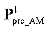
cell 1;
cell 1; g2,1 is the multi-cell decoding matrix for terminal (2, 1); g2,2 is the multi-cell decoding matrix for terminal (2, 2); I 3×3 is a unit diagonal matrix having 3 lines and 3 columns; 0 3×2 is an all zero matrix having 3 lines and 2 columns; 0 6×1 is an all zero column vector having 6 lines and 1 column. - The decoding matrices g 2,1 and g 2,2 may be obtained by solving equation (4) and these two decoding matrices are the decoding matrices for the two users (i.e. terminal (2, 1) and terminal (2, 2)) in
cell 2. - The equivalent interference channel matrix
channel 

where
cell 1 and is obtained by solving equation (5). - The above equation (4) is equal to the following equation:

where

- According to equation (6), interference signals from the transmitter of
cell 1 to two terminals incell 2 are aligned to the same direction, i.e. the direction indicated byvector 
cell 1 transmitting data to a terminal incell 1 is orthogonal to the direction indicated byvector 
cell 1 to terminals incell 2 will be produced. Equation (5) is defined for this orthogonality. Combining equation (4) and (5), the interference between cells may be eliminated. At the same time, since interference signals are substantially aligned to the same direction, more directions for useful signals may be left. -
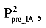
cell 2, i.e. the multi-cell pre-coding matrix ofcell 2, the multi-cell decoding matrix for terminal (1, 1) and the multi-cell decoding matrix for terminal (1, 2) may be obtained. - For example, the equivalent interference channel matrix and the decoding matrices for two terminals in
cell 1 are obtained by constituting a linear equation using the downlink channel matrices of the channels betweentransmitter 1 and the two terminals withincell 2 and the antenna mappingmatrix 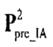
cell 2. The multi-cell pre-coding matrix is computed according to the orthogonality between the equivalent interference channel matrix and the multi-cell pre-coding matrix. For example, the following linear equation is constituted by the downlink channel matrices and the antenna mappingmatrix 

where H 2,1,1 is the downlink channel from the transmitter ofcell 2 to terminal 1 (i.e., terminal (1, 1)) withincell 1; H 2,1,2 is the downlink channel from the transmitter ofcell 2 to terminal 2 (i.e., terminal (1, 2)) withincell 1;
cell 2;
cell 2; g 1,1 is the multi-cell decoding matrix for terminal (1, 1); g 1,2 is the multi-cell decoding matrix for terminal (1, 2); I 3×3 is a unit diagonal matrix having 3 lines and 3 columns; 0 3×2 is an all zero matrix having 3 lines and 2 columns; 0 6×1 is an all zero column vector having 6 lines and 1 column. - The decoding matrices g 1,1 and g 1,2 may be obtained by solving equation (4') and these two decoding matrices are the decoding matrices for the two terminals (i.e. terminal (1, 1) and terminal (1, 2)) in
cell 1. - The equivalent interference channel
matrix 

where
cell 2 and is obtained by solving equation (5'). - The above equation (4') is equal to the following equation:

where

- According to equation (6'), interference signals from the transmitter of
cell 2 to two terminals incell 1 are aligned to the same direction, i.e. the direction indicated byvector 
cell 2 transmitting data to a terminal incell 2 is orthogonal to the direction indicated byvector 
cell 2 to terminals incell 1 will be produced. Equation (5') is defined for this orthogonality. Combining equation (4') and (5'), the interference between cells may be eliminated. At the same time, since interference signals are substantially aligned to the same direction, more directions for useful signals may be left. - According to an embodiment of the invention, an operation of the single cell multi-user pre-coding
matrix computing unit 24 may be described with reference to the following example (taking the transmitter ofcell 1 as an example). - A equivalent multi-user multi-antenna system matrix is constituted by the downlink channel matrices between the transmitter in
cell 1 and the terminal (1,1) and (1, 2), the resultant antenna mappingmatrix 
cell 1, the multi-cell pre-codingmatrix 
cell 1.
where
cell 1;
cell 1;
cell 1;


cell 1 to the terminal (1, 1) incell 1; H 1,1,2 is the downlink channel matrix from the transmitter ofcell 1 to the terminal (1, 2) incell 1; v 1,k (k=1 or 2) is a noise received by terminal k incell 1. - According to the matrix computed by equation (7), the following input and output relation of an equivalent multi-user system may be obtained:

where
cell 1;
cell 1;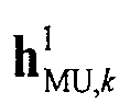
cell 1;
cell 1; s 1,l is the data signal of the user terminal l incell 1; s 1,k is the data signal of the user terminal k incell 1;
cell 1. - According to different principles,


- Methods for computing the linear pre-coding and decoding matrices comprise but are not limited to: non-iterative algorithms such as Zero Forcing (ZF) algorithm, Minimum Mean Square Error (MMSE) algorithm, Matching Filtering (MF) algorithm, Block Diagonalization (BD) algorithm and Maximum Signal to Leakage and Noise Ratio (SLNR) algorithm, and iterative algorithms such as Maximum Sum Rate Iterative algorithm and Minimum Mean Square Error (MMSE) Iterative algorithm. The Minimum Mean Square Error (MMSE) algorithm, Maximum Signal to Leakage and Noise Ratio (SLNR) algorithm, Maximum Sum Rate Iterative algorithm and Minimum Mean Square Error (MMSE) Iterative algorithm need to use the equivalent interference and noise measurement values fed from the terminals. The Zero Forcing (ZF) algorithm, Matching Filtering (MF) algorithm and Block Diagonalization (BD) algorithm need not to use the equivalent interference and noise measurement values fed from the terminals.
- Taking the transmitter of
cell 2 as an example, an equivalent multi-user multi-antenna system matrix is constituted by the downlink channel matrices between the transmitter incell 2 and the terminals (2, 1) and (2, 2), the antenna mappingmatrix 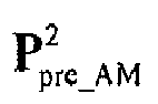
cell 2, the multi-cell pre-codingmatrix 
cell 2.
where
cell 2;
cell 2;
cell 2;


cell 2 to the terminal (2, 1) incell 2; H 2,2,2 is the downlink channel matrix from the transmitter ofcell 2 to the terminal (2, 2) incell 2; v 2,k (k=1 or 2) is a noise received by terminal k incell 2. - According to the matrix computed by equation (7'), the following input and output relation of an equivalent multi-user system may be obtained:

where
cell 2;
cell 2;
cell 2;
cell 2; s 2,l is the data signal of the user terminal / incell 2; s 2,k is the data signal of the user terminal k incell 2;
cell 2. - According to different principles,


- Methods for computing the linear pre-coding and decoding matrices comprise but are not limited to: non-iterative algorithms such as Zero Forcing (ZF) algorithm, Minimum Mean Square Error (MMSE) algorithm, Matching Filtering (MF) algorithm, Block Diagonalization (BD) algorithm and Maximum Signal to Leakage and Noise Ratio (SLNR) algorithm, and iterative algorithms such as Maximum Sum Rate Iterative algorithm and Minimum Mean Square Error (MMSE) Iterative algorithm. The Minimum Mean Square Error (MMSE) algorithm, Maximum Signal to Leakage and Noise Ratio (SLNR) algorithm, Maximum Sum Rate Iterative algorithm and Minimum Mean Square Error (MMSE) Iterative algorithm need to use the equivalent interference and noise measurement value fed from the terminal. The Zero Forcing (ZF) algorithm, Matching Filtering (MF) algorithm and Block Diagonalization (BD) algorithm need not to use the equivalent interference and noise measurement value fed from the terminal.
-
Fig. 5 is a flow chart showing a coordinating communication method based on the interference alignment according to an embodiment of the invention. - For simplicity, assuming k in
Fig. 5 is 1 or 2. Therefore,cell 1 andcell 2 are coordinating cells, transmitter (TX1) ofcell 1 transmits data to terminal (1, 1) and (1, 2), i.e. RX1,1 and RX1,2, transmitter (TX2) ofcell 2 transmits data to terminal (2, 1) and (2, 2), i.e. RX2,1 and RX2,2. The description with reference toFig. 5 is for the TDD system. However, those skilled in the art may understand that the invention may also be used in the FDD system. The method according to an embodiment of the invention comprises the following steps. - In step S51, the terminal (1, 1) transmits uplink detecting signals SRS to the transmitter of
cell 1 and the transmitter ofcell 2. The transmitter ofcell 1 and the transmitter ofcell 2 receive the uplink detecting signal SRS respectively and thechannel estimation unit 21 of the two transmitters perform the channel estimation to obtain the uplink channels of the terminal (1, 1). The transmitter ofcell 1 and the transmitter ofcell 2 obtain the downlink channels of the terminal (1, 1) according to a reciprocity property between uplink and downlink channels of the TDD system. The terminals (1, 2), (2, 1) and (2, 2) perform similar operations and the transmitter ofcell 1 and the transmitter ofcell 2 obtain the downlink channel matrices of the terminals. - Optionally, the terminal (1, 1) may measure an intensity of the interference from the non-coordinating cells and the noise signals and then feed the intensity of the interference and noise signals back to the transmitter of
cell 1 and the transmitter ofcell 2 by sending a feed-back signal. Next, the transmitter ofcell 1 and the transmitter ofcell 2 receive the feed-back signal from the terminal (1, 1) and obtain the intensity of the interference from non-cooperating cells and noise signals received by the terminal (1, 1), i.e., the equivalent interference and noise measurement value of terminal (1, 1). Terminals (1, 2), (2, 1) and (2, 2) perform similar operations and the transmitter ofcell 1 and the transmitter ofcell 2 receive the intensity of the interference from the coordinating cells and noise signals received by these terminals, i.e., the equivalent interference and noise measurement value of terminal (1, 2), (2, 1) and (2, 2). The interference and noise measurement values obtained may be used in the computation for the multi-user pre-coding matrix and the multi-user pre-decoding matrix. - In step S52, the antenna mapping
matrix computing unit 22 of the transmitter ofcell 1 computes the antenna mapping matrix according to the information of the downlink channel between the transmitter ofcell 1 and the terminals (1, 1) and (1, 2). According to the above formulae (4) and (5), the multi-cell pre-codingmatrix computing unit 23 of the transmitter ofcell 1 computes the multi-cell decoding matrices for the terminals (2, 1) and (2, 2) and the multi-cell pre-coding matrix of the transmitter ofcell 1 according to the information of the downlink channel between the transmitter ofcell 1 and the terminals (2, 1) and (2, 2) in the coordinating cell and according to the antenna mapping matrix of the transmitter ofcell 1. For example, the decoding matrices of the two terminals incell 2 and the equivalent interference channel matrix are obtained by constituting a linear equation using the downlink channel matrices between the transmitter ofcell 1 and the terminals of thecell 2 and the antenna mapping matrix of the transmitter ofcell 1. Then, the multi-cell pre-coding matrix of the transmitter ofcell 1 may be computed according to the orthogonality between the equivalent interference channel matrix and the multi-cell pre-coding matrix. - As shown in
Fig. 5 , the transmitter ofcell 1 notifiescell 2 the multi-cell decoding matrices of the terminals (2, 1) and (2, 2) through the cable connection. In step S53, the decoding matrices g 2,1 and g 2,2 are transmitted to the transmitter ofcell 2 through a backhaul link between the transmitter ofcell 1 and the transmitter ofcell 2 and then the transmitter ofcell 2 transmits the decoding matrices to the terminals (2, 1) and (2, 2) through the downlink (DL) signaling. - Similarly, the antenna mapping
matrix computing unit 22 of the transmitter ofcell 2 computes the antenna mapping matrix according to the information of the downlink channel between the transmitter ofcell 2 and the terminals (2, 1) and (2, 2). The multi-cell pre-codingmatrix computing unit 23 of the transmitter ofcell 2 computes the multi-cell decoding matrices for the terminals (1, 1) and (1, 2) and the multi-cell pre-coding matrix of the transmitter ofcell 2 according to the information of the downlink channel between the transmitter ofcell 2 and the terminals (2, 1) and (2, 2) in the coordinatingcell 1 and according to the antenna mapping matrix of the transmitter ofcell 2. For example, the decoding matrices of the two terminals incell 1 and the equivalent interference channel matrix are obtained by constituting a linear equation using the channel matrix between the transmitter ofcell 2 and the terminals ofcell 1 and the antenna mapping matrix of the transmitter ofcell 2. Then, the multi-cell pre-coding matrix of the transmitter ofcell 2 may be computed according to the orthogonality between the equivalent interference channel matrix and the multi-cell pre-coding matrix. The single cell multi-user pre-codingmatrix computing unit 24 computes the equivalent single cell multi-user channel matrix ofcell 2 and thus the single cell multi-user pre-coding matrix ofcell 2 according to the downlink channel matrices of the channels between the transmitter ofcell 2 and terminals (2, 1) and (2, 2), the antenna mapping matrix of the transmitter ofcell 2, the multi-cell pre-decoding matrix ofcell 2 and the multi-cell decoding matrices for terminals (2, 1) and (2, 2). According to another embodiment of the invention, the single cell multi-user pre-coding matrix ofcell 1 may be computed according to the equivalent single cell multi-user channel matrix and the equivalent interference and noise measurement values received by the terminals (2, 1) and (2, 2). - The transmitter of
cell 2 notifies the terminals (2, 1) and (2, 2) of their multi-cell decoding matrices respectively through the down link. The transmitter ofcell 2 performs the single cell multi-user pre-coding, multi-cell pre-coding and antenna mapping on the data and/or demodulated reference signal of the terminals (2, 1) and (2, 2) and finally sends the result to the user terminal through the down link. - In step S54, the single cell multi-user pre-coding
matrix computing unit 24 of the transmitter ofcell 1 computes the equivalent single cell multi-user channel matrix and thus the single cell multi-user pre-coding matrix ofcell 1 according to the downlink channel matrices of the channels between the transmitter ofcell 1 and terminals (1, 1) and (1, 2), the antenna mapping matrix of the transmitter ofcell 1, the multi-cell pre-decoding matrix ofcell 1 and the multi-cell decoding matrices for terminals (1, 1) and (1, 2). According to another embodiment of the invention, the single cell multi-user pre-coding matrix ofcell 1 may be computed according to the equivalent single cell multi-user channel matrix and the equivalent interference and noise measurement values received by the terminals (1, 1) and (1, 2). - In step S55, the single cell multi-user
pre-coding unit 25, the multi-cellpre-coding unit 26 and theantenna mapping unit 27 ofcell 1 perform the single cell multi-user pre-coding, multi-cell pre-coding and antenna mapping on the data and/or demodulated reference signal of the terminals (1, 1) and (1, 2) and finally transmit to the user terminal through the down link. - The transmitter of
cell 2 notifies the transmitter ofcell 1 of the multi-cell decoding matrices of the terminals (1, 1) and (1, 2) through the cable connection. The transmitter ofcell 1 transmits multi-cell decoding matrices to the terminals (1, 1) and (1, 2) through the down link. - Each terminal recovers useful signals according to the received multi-cell decoding matrix. The multi-cell decoding unit of each terminal decodes the downlink user data by using the received multi-cell decoding matrix to eliminate the interference between cells. The channel estimation unit of each terminal estimates the single cell multi-user equivalent channel according to the multi-cell decoding matrix and the downlink signal and finally computes the single cell multi-user decoding matrix according to the single cell multi-user equivalent channel. Then the multi-user decoding unit of each terminal recovers useful signals according to the single cell multi-user decoding matrix and detects the downlink data.
- Although explanatory embodiments have been shown and described, it would be appreciated by those skilled in the art that changes, alternatives, and modifications all falling into the scope of the claims and their equivalents may be made in the embodiments without departing from spirit and principles of the disclosure and the scope of the invention is specified in the claims.
Claims (16)
- A pre-coding method using an interference alignment scheme, the method comprising:computing an antenna mapping matrix using the downlink channel state information matrices of the channels between the transmitter and the terminals within the cell covered by the transmitter, wherein the antenna mapping matrix is used for antenna mapping for the current transmitter so as to perform an interference alignment scheme;computing a multi-cell pre-coding matrix for the transmitter and a multi-cell decoding matrix for each terminal within the coordinating cell using the downlink channel state information matrices of the channels between the transmitter and the terminals within the coordinating cell and using the antenna mapping matrix;computing a single cell multi-user pre-coding matrix for the current transmitter using the downlink channel state information matrices of the channels between the transmitter and the terminals within the cell covered by the transmitter, the antenna mapping matrix, the multi-cell pre-decoding matrix, and the multi-cell decoding matrices for the terminals within the cell covered by the current transmitter, the multi-cell decoding matrices are received from the transmitter of the coordinating cell; andpre-coding user data using the single cell multi-user pre-coding matrix and the multi-cell pre-decoding matrix and performing an antenna mapping for the pre-coded user data using the antenna mapping matrix.
- The method according to claim 1, further comprising:transmitting the multi-cell decoding matrices for the terminals within the coordinating cell to the transmitter of the coordinating cell by the transmitter.
- The method according to claim 1, wherein the step of computing an antenna mapping matrix comprises:performing a singular value decomposition on a downlink channel matrix H and obtaining USVH, selecting from the unitary matrix V a number of columns which is equal to the number of antennas at a transmitter in an equivalent system to constitute the antenna mapping matrix, in which a column vector of the unitary matrix U constitutes a left singular value vector, a column vector of the unitary matrix V constitutes a right singular value vector, diagonal values of the diagonal matrix S are singular values and superscript H represents a conjugate transpose operation on a matrix.
- The method according to claim 1, wherein the step of computing an antenna mapping matrix is realized by generating a

- The method according to claim 1, wherein the step of computing a multi-cell pre-coding matrix of the current transmitter comprises:computing an equivalent interference channel matrix by constituting a linear equation using the downlink channel state information matrices of the channels between the current transmitter and the terminals within the coordinating cell and the antenna mapping matrix; andcomputing the multi-cell pre-coding matrix based on the equivalent interference channel matrix.
- The method according to claim 1, wherein the step of computing a single cell multi-user pre-coding matrix of the current transmitter comprises:constituting an equivalent multi-user multi-antenna system by using the downlink channel state information matrices of the channels between the current transmitter and the terminals within the current cell, the antenna mapping matrix, the multi-cell pre-coding matrix and the multi-cell decoding matrices of the terminals within the current cell; andcomputing a linear pre-coding matrix for the transmitter and the decoding matrices for the terminals within the current cell by using a multi-user pre-coding algorithm and a multi-user decoding algorithm based on the equivalent multi-user multi-antenna system.
- The method according to claim 1, wherein the step of computing a single cell multi-user pre-coding matrix of the current transmitter comprises:constituting an equivalent multi-user multi-antenna system by using the downlink channel state information matrices of the channels between the current transmitter and the terminals within the current cell, the antenna mapping matrix, the multi-cell pre-coding matrix and the multi-cell decoding matrices of the terminals within the current cell; andcomputing a linear pre-coding matrix for the transmitter and the decoding matrices for the terminals within the current cell by using a multi-user pre-coding algorithm and a multi-user decoding algorithm based on the equivalent multi-user multi-antenna system and a noise power measurement value received from the terminals within the current cell.
- A transmitter, comprising:an antenna mapping matrix computing unit, configured to compute an antenna mapping matrix using the downlink channel state information matrices of the channels between the current transmitter and the terminals within a cell covered by the transmitter, wherein the antenna mapping matrix is used for antenna mapping for the transmitter so as to perform an interference alignment scheme;a multi-cell pre-coding matrix computing unit, configured to compute a multi-cell pre-coding matrix for the transmitter and a multi-cell decoding matrix for each terminal within the coordinating cell using the downlink channel state information matrices of the channels between the transmitter and the terminals within the coordinating cell and using the antenna mapping matrix;a single cell multi-user pre-coding matrix computing unit, configured to compute a single cell multi-user pre-coding matrix for the current transmitter using the downlink channel state information matrices of the channels between the transmitter and the terminals within the cell covered by the transmitter, the antenna mapping matrix, the multi-cell pre-decoding matrix, and the multi-cell decoding matrices for the terminals within the cell covered by the current transmitter, the multi-cell decoding matrices are received from the transmitter of the coordinating cell; anda pre-coding unit, configured to pre-code user data using the single cell multi-user pre-coding matrix and the multi-cell pre-decoding matrix, and perform an antenna mapping for the pre-coded user data using the antenna mapping matrix.
- The transmitter according to claim 8, wherein the transmitter transmits the multi-cell decoding matrices for the terminals within the coordinating cell to the transmitter of the coordinating cell.
- The transmitter according to claim 8, wherein the antenna mapping matrix computing unit performs a singular value decomposition on a downlink channel matrix H and obtains USVH, selects from the unitary matrix V a number of columns which is equal to the number of antennas at a transmitter in an equivalent system to constitute the antenna mapping matrix, in which a column vector of the unitary matrix U constitutes a left singular value vector, a column vector of the unitary matrix V constitutes a right singular value vector, diagonal values of the diagonal matrix S are singular values and superscript H represents a conjugate transpose operation on a matrix.
- The transmitter according to claim 8, wherein the antenna mapping matrix computing unit generates a

- The transmitter according to claim 8, wherein the multi-cell pre-coding matrix computing unit computes an equivalent interference channel matrix by constituting a linear equation using downlink channel state information matrices of the channel from the transmitter to the terminals within the coordinating cell and the antenna mapping matrix; and computes the multi-cell pre-coding matrix based on the equivalent interference channel matrix.
- The transmitter according to claim 8, wherein the single cell multi-user pre-coding matrix computing unit constitutes an equivalent multi-user multi-antenna system by using the downlink channel state information matrices of the channels between the current transmitter and the terminals within the current cell , the antenna mapping matrix, the multi-cell pre-coding matrix and the multi-cell decoding matrices of the terminals within the current cell; and computes a linear pre-coding matrix and a decoding matrix by using a multi-user pre-coding algorithm and a multi-user decoding algorithm based on the equivalent multi-user multi-antenna system.
- The transmitter according to claim 8, wherein the single cell multi-user pre-coding matrix computing unit constitutes an equivalent multi-user multi-antenna system by using the downlink channel state information matrices of the terminals in the current communication cell, the antenna mapping matrix, the multi-cell pre-coding matrix and the multi-cell decoding matrices; and computes a linear pre-coding matrix for the transmitter and the decoding matrices for the terminals within the current cell by using a multi-user pre-coding algorithm and a multi-user decoding algorithm based on the equivalent multi-user multi-antenna system and a noise power measurement value received from the terminals within the current cell..
- A pre-decoding method based on an interference alignment scheme, the method comprising:receiving a multi-cell decoding matrix from the transmitter of the serving cell by a mobile terminal;decoding a downlink user data using the multi-cell decoding matrix;estimating a single cell multi-user equivalent channel using a downlink signal from the transmitter and the multi-cell decoding matrix obtained from the previous step, and computing a single cell multi-user decoding matrix according to the resultant single cell multi-user equivalent channel; anddetecting downlink data using the single cell multi-user decoding matrix obtained from the previous step.
- A mobile terminal, comprising:a multi-cell decoding unit, configured to receive a multi-cell decoding matrix from a transmitter of a serving cell and decode a downlink user data using the multi-cell decoding matrix;a channel estimation unit, configured to estimate a single cell multi-user equivalent channel according to a downlink signal from the transmitter and the multi-cell decoding matrix obtained in the previous step, and compute a single cell multi-user decoding matrix according to the resultant single cell multi-user equivalent channel; anda multi-user decoding unit, configured to detect downlink data according to the single cell multi-user decoding matrix obtained in the previous step.
Applications Claiming Priority (1)
| Application Number | Priority Date | Filing Date | Title |
|---|---|---|---|
| CN201110263416.9A CN102983935B (en) | 2011-09-07 | 2011-09-07 | Precoding, pre-coding/pre-decoding method and emitter and mobile terminal based on interference alignment |
Publications (3)
| Publication Number | Publication Date |
|---|---|
| EP2568676A2 true EP2568676A2 (en) | 2013-03-13 |
| EP2568676A3 EP2568676A3 (en) | 2015-04-08 |
| EP2568676B1 EP2568676B1 (en) | 2017-03-01 |
Family
ID=46800110
Family Applications (1)
| Application Number | Title | Priority Date | Filing Date |
|---|---|---|---|
| EP12183117.6A Not-in-force EP2568676B1 (en) | 2011-09-07 | 2012-09-05 | Pre-coding method, pre-decoding method, transmitter and mobile terminal based on interference alignment |
Country Status (4)
| Country | Link |
|---|---|
| US (1) | US8861637B2 (en) |
| EP (1) | EP2568676B1 (en) |
| JP (1) | JP6018848B2 (en) |
| CN (1) | CN102983935B (en) |
Cited By (1)
| Publication number | Priority date | Publication date | Assignee | Title |
|---|---|---|---|---|
| EP3229513A4 (en) * | 2014-12-03 | 2018-07-18 | Sony Corporation | Small cell interference coordination method and wireless communication device |
Families Citing this family (22)
| Publication number | Priority date | Publication date | Assignee | Title |
|---|---|---|---|---|
| US8725101B2 (en) * | 2011-07-06 | 2014-05-13 | Broadcom Corporation | Wireless device and method of operation |
| CN102905320B (en) * | 2012-09-24 | 2015-04-01 | 上海交通大学 | Monotone optimization method for maximizing multi-cell downlink weighting and rate |
| KR102050928B1 (en) * | 2012-10-16 | 2019-12-03 | 삼성전자주식회사 | Method and apparatus for user equipment selection in wireless communication system |
| EP2984801A1 (en) * | 2013-04-09 | 2016-02-17 | Interdigital Patent Holdings, Inc. | Joint precoding and multivariate backhaul compression for the downlink of cloud radio access networks |
| CN103475399B (en) * | 2013-09-10 | 2017-06-27 | 华为技术有限公司 | Interference alignment schemes and equipment |
| CN103607260B (en) * | 2013-11-15 | 2017-04-12 | 华侨大学 | System total interference leakage minimum pre-coding matrix group selection algorithm based on MIMO |
| CN103701560B (en) * | 2013-11-29 | 2019-04-12 | 北京邮电大学 | Precoding method based on interference alignment |
| CN104980380A (en) * | 2014-04-14 | 2015-10-14 | 株式会社Ntt都科摩 | Base station, communication system and method thereof |
| EP3236596B1 (en) * | 2014-12-16 | 2020-04-08 | Fujitsu Limited | Downlink channel estimation method and apparatus based on sounding reference signal, and communication system |
| EP3276860B1 (en) * | 2015-03-26 | 2019-09-04 | NTT DoCoMo, Inc. | Radio communication control method and radio communication system |
| EP3411958B1 (en) * | 2016-02-04 | 2019-10-23 | Telefonaktiebolaget LM Ericsson (PUBL) | A method for adapting a beam shape of a beam |
| KR102468311B1 (en) * | 2016-05-11 | 2022-11-18 | 한국전자통신연구원 | Apparatus and Method for Align Interference in Cellular Communication Network |
| CN106160814B (en) * | 2016-06-14 | 2019-04-19 | 中国电子科技集团公司第五十四研究所 | A Multi-Base Station Cooperative Downlink Transmission Method Based on Interference Alignment Technology |
| CN110495108A (en) * | 2017-04-07 | 2019-11-22 | 英特尔公司 | Method and device for processing data signals transmitted to a multi-stream terminal |
| US9991972B1 (en) * | 2017-04-26 | 2018-06-05 | Cisco Technology, Inc. | Remote radio head calibration |
| CN109905155B (en) * | 2019-01-21 | 2021-06-04 | 郑州轻工业学院 | An interference management method and wireless communication system based on internal and external concatenated precoding |
| US11456760B1 (en) * | 2021-03-05 | 2022-09-27 | Motorola Solutions, Inc. | Linearizing narrowband carriers with low resolution predistorters |
| CN113078932B (en) * | 2021-03-29 | 2022-04-01 | 东南大学 | An intelligent reflective surface-assisted precoding design method for downlink transmission |
| US11539557B1 (en) * | 2021-12-16 | 2022-12-27 | Qualcomm Incorporated | Multi-level coding for power efficient channel coding |
| CN116722896A (en) * | 2023-06-12 | 2023-09-08 | 华中科技大学 | Super-directional antenna array multi-user precoding method, equipment and medium |
| US12119911B1 (en) | 2023-06-12 | 2024-10-15 | Huazhong University Of Science And Technology | Superdirective antenna array multi-user precoding method, device and medium |
| CN120568489B (en) * | 2025-07-31 | 2025-12-26 | 荣耀终端股份有限公司 | Data transmission method and communication device under channel estimation based on air calculation |
Family Cites Families (28)
| Publication number | Priority date | Publication date | Assignee | Title |
|---|---|---|---|---|
| CN101325741B (en) * | 2007-06-14 | 2012-12-12 | Nxp股份有限公司 | Method and system for operating MU-MIMO wireless communication system |
| CN101373998B (en) * | 2007-08-20 | 2012-07-25 | 上海贝尔阿尔卡特股份有限公司 | Low information interactive multi-base station collaboration MIMO as well as scheduling method and apparatus thereof |
| KR101561704B1 (en) * | 2008-06-10 | 2015-10-20 | 한국전자통신연구원 | Multi-cell cooperative communication system and terminal device |
| US20090323849A1 (en) * | 2008-06-30 | 2009-12-31 | Interdigital Patent Holdings, Inc. | Method and apparatus for performing multiple-input multiple-output wireless communications |
| US20100035555A1 (en) * | 2008-08-05 | 2010-02-11 | Interdigital Patent Holdings, Inc. | Method and apparatus for implementing multi-cell cooperation techniques |
| US8693442B2 (en) * | 2008-09-22 | 2014-04-08 | Blackberry Limited | Multi-site MIMO cooperation in cellular network |
| CN101771507B (en) * | 2009-01-05 | 2013-11-13 | 上海贝尔阿尔卡特股份有限公司 | Method and device for eliminating intercell interference in multi-cell MIMO (Multiple Input Multiple Output) wireless communication network |
| KR101524689B1 (en) * | 2009-03-03 | 2015-06-01 | 삼성전자주식회사 | Communication system and method for selectively feedbacking information about interference channels for interference alignment |
| CN102439868B (en) * | 2009-03-16 | 2014-09-17 | 华为技术有限公司 | Method, communication system and related equipments for data transmission |
| US8369429B2 (en) * | 2009-03-18 | 2013-02-05 | Lg Electronics Inc. | Method and apparatus for transmitting precoding matrix index in a wireless communication system using CoMP scheme |
| EP2242187B1 (en) * | 2009-04-14 | 2015-10-28 | Fraunhofer-Gesellschaft zur Förderung der angewandten Forschung e.V. | Method and device for data processing in a communication network |
| WO2010123295A2 (en) * | 2009-04-24 | 2010-10-28 | 한국전자통신연구원 | Cooperative communication method in cellular wireless communication system and terminal for performing the method |
| CN101877609B (en) * | 2009-04-30 | 2013-06-12 | 富士通株式会社 | Communication device, base station and multipoint cooperative communication method |
| EP2429087B1 (en) * | 2009-05-12 | 2016-07-13 | Huawei Technologies Co., Ltd. | Interference cancellation method and data transmission device |
| US20100304773A1 (en) * | 2009-05-27 | 2010-12-02 | Ramprashad Sean A | Method for selective antenna activation and per antenna or antenna group power assignments in cooperative signaling wireless mimo systems |
| EP2448136B1 (en) * | 2009-06-23 | 2019-01-23 | Alcatel Lucent | Method for channel status information feedback and device thereof |
| KR101615116B1 (en) * | 2009-07-13 | 2016-04-25 | 삼성전자주식회사 | Precoding method for femto cell or pico cell and communication system of using the method |
| US8379705B2 (en) * | 2009-08-04 | 2013-02-19 | Qualcomm Incorporated | Hierarchical feedback of channel state information for wireless communication |
| CN102123525A (en) * | 2010-01-07 | 2011-07-13 | 夏普株式会社 | Interference coordination method of downlink multi-antenna multiple base stations and base station |
| US8577310B2 (en) * | 2010-02-05 | 2013-11-05 | Futurewei Technologies, Inc. | System and method for transceivers in a wireless network |
| KR101681094B1 (en) * | 2010-06-29 | 2016-12-01 | 삼성전자주식회사 | Method and apparatus for controlling transmit power in wireless network |
| CN101908948B (en) * | 2010-07-15 | 2012-11-14 | 中国科学技术大学 | Characteristic sub-channel-based interference alignment pre-coding matrix optimizing method |
| KR20120032777A (en) * | 2010-09-29 | 2012-04-06 | 삼성전자주식회사 | Method and apparatus for determining downlink beamforming vectors in hierarchical cell communication system |
| EP2638652A2 (en) * | 2010-11-10 | 2013-09-18 | Interdigital Patent Holdings, Inc. | Method and apparatus for interference mitigation via successive cancellation in heterogeneous networks |
| KR101588712B1 (en) * | 2010-11-16 | 2016-01-26 | 삼성전자주식회사 | Method and apparatus of controlling inter cell interference based on cooperation of intra cell terminals |
| WO2012093904A2 (en) * | 2011-01-06 | 2012-07-12 | 엘지전자 주식회사 | Interference alignment method and device in cellular network |
| US8811514B2 (en) * | 2011-05-06 | 2014-08-19 | Dynamic Invention Llc | Partial interference alignment for K-user MIMO interference channels |
| US8964871B2 (en) * | 2012-05-14 | 2015-02-24 | Blackberry Limited | Codebook based downlink multi-user interference alignment scheme |
-
2011
- 2011-09-07 CN CN201110263416.9A patent/CN102983935B/en not_active Expired - Fee Related
-
2012
- 2012-09-05 EP EP12183117.6A patent/EP2568676B1/en not_active Not-in-force
- 2012-09-07 US US13/606,383 patent/US8861637B2/en active Active
- 2012-09-07 JP JP2012197739A patent/JP6018848B2/en active Active
Non-Patent Citations (2)
| Title |
|---|
| C. SUH: "Downlink Interference Alignment", GLOBECOM, 2010 |
| W. SHIN: "On the Design of Interference Alignment Scheme for Two-Cell MIMO Interfering Broadcast Channels", IEEE TRANS. ON WIRELESS COMM., 2011 |
Cited By (1)
| Publication number | Priority date | Publication date | Assignee | Title |
|---|---|---|---|---|
| EP3229513A4 (en) * | 2014-12-03 | 2018-07-18 | Sony Corporation | Small cell interference coordination method and wireless communication device |
Also Published As
| Publication number | Publication date |
|---|---|
| EP2568676A3 (en) | 2015-04-08 |
| US20130058433A1 (en) | 2013-03-07 |
| JP2013059028A (en) | 2013-03-28 |
| CN102983935A (en) | 2013-03-20 |
| EP2568676B1 (en) | 2017-03-01 |
| JP6018848B2 (en) | 2016-11-02 |
| US8861637B2 (en) | 2014-10-14 |
| CN102983935B (en) | 2017-10-27 |
Similar Documents
| Publication | Publication Date | Title |
|---|---|---|
| EP2568676B1 (en) | Pre-coding method, pre-decoding method, transmitter and mobile terminal based on interference alignment | |
| US8953704B2 (en) | Wireless communication apparatus, wireless communication system and wireless communication method | |
| US11290169B2 (en) | Methods, systems and units of a distributed base station system for handling of downlink communication | |
| US9258823B2 (en) | Interference suppression method and apparatus in multi-point coordinated transmission system | |
| EP2618500A1 (en) | Wireless communication control method, wireless communication system, wireless base station and mobile terminal | |
| US10181965B2 (en) | Channel estimation method and apparatus in wireless communication system | |
| US8401106B2 (en) | Interference rejection combining for multi-user MIMO telecommunications system | |
| US9118372B2 (en) | Method and apparatus for downlink multiuser MIMO transmission in a wireless network | |
| US9484999B2 (en) | Method and device for transmitting signal | |
| CN103312390B (en) | Based on the method for precoding of interference alignment, emitter and equipment | |
| CN101771507B (en) | Method and device for eliminating intercell interference in multi-cell MIMO (Multiple Input Multiple Output) wireless communication network | |
| US20130301756A1 (en) | Apparatus and Method for Decoding a Received Signal | |
| EP2810381B1 (en) | Joint transmit and receive procedure | |
| EP2485423B1 (en) | Precoding method in cooperative relay system, communication apparatus and relay apparatus | |
| CN102790634A (en) | Precoding method and base station in multi-cell cooperative communication and communication system | |
| WO2020142794A2 (en) | Methods and apparatus for channel estimation and precoding with incomplete channel observation and channel state information feedback | |
| CN103312393B (en) | A kind of uplink coordinated multipoint iterations and system | |
| CN105827354B (en) | For interfering the method and apparatus for carrying out blind Detecting to transmission mode eliminated | |
| US8767880B2 (en) | Processing data in a receiver circuit and receiver circuit | |
| US20130083863A1 (en) | Apparatus and method for low complexity feedback in a mimo wireless network | |
| CN102904693B (en) | The precoding implementation method and device of coordinated multipoint transmission |
Legal Events
| Date | Code | Title | Description |
|---|---|---|---|
| PUAI | Public reference made under article 153(3) epc to a published international application that has entered the european phase |
Free format text: ORIGINAL CODE: 0009012 |
|
| AK | Designated contracting states |
Kind code of ref document: A2 Designated state(s): AL AT BE BG CH CY CZ DE DK EE ES FI FR GB GR HR HU IE IS IT LI LT LU LV MC MK MT NL NO PL PT RO RS SE SI SK SM TR |
|
| AX | Request for extension of the european patent |
Extension state: BA ME |
|
| PUAL | Search report despatched |
Free format text: ORIGINAL CODE: 0009013 |
|
| AK | Designated contracting states |
Kind code of ref document: A3 Designated state(s): AL AT BE BG CH CY CZ DE DK EE ES FI FR GB GR HR HU IE IS IT LI LT LU LV MC MK MT NL NO PL PT RO RS SE SI SK SM TR |
|
| AX | Request for extension of the european patent |
Extension state: BA ME |
|
| RIC1 | Information provided on ipc code assigned before grant |
Ipc: H04L 25/03 20060101AFI20150305BHEP Ipc: H04B 7/04 20060101ALI20150305BHEP |
|
| 17P | Request for examination filed |
Effective date: 20150902 |
|
| RBV | Designated contracting states (corrected) |
Designated state(s): AL AT BE BG CH CY CZ DE DK EE ES FI FR GB GR HR HU IE IS IT LI LT LU LV MC MK MT NL NO PL PT RO RS SE SI SK SM TR |
|
| 17Q | First examination report despatched |
Effective date: 20160308 |
|
| GRAP | Despatch of communication of intention to grant a patent |
Free format text: ORIGINAL CODE: EPIDOSNIGR1 |
|
| INTG | Intention to grant announced |
Effective date: 20160908 |
|
| GRAS | Grant fee paid |
Free format text: ORIGINAL CODE: EPIDOSNIGR3 |
|
| GRAA | (expected) grant |
Free format text: ORIGINAL CODE: 0009210 |
|
| AK | Designated contracting states |
Kind code of ref document: B1 Designated state(s): AL AT BE BG CH CY CZ DE DK EE ES FI FR GB GR HR HU IE IS IT LI LT LU LV MC MK MT NL NO PL PT RO RS SE SI SK SM TR |
|
| REG | Reference to a national code |
Ref country code: GB Ref legal event code: FG4D |
|
| REG | Reference to a national code |
Ref country code: CH Ref legal event code: EP Ref country code: AT Ref legal event code: REF Ref document number: 872494 Country of ref document: AT Kind code of ref document: T Effective date: 20170315 |
|
| REG | Reference to a national code |
Ref country code: IE Ref legal event code: FG4D |
|
| REG | Reference to a national code |
Ref country code: DE Ref legal event code: R096 Ref document number: 602012029144 Country of ref document: DE |
|
| REG | Reference to a national code |
Ref country code: NL Ref legal event code: MP Effective date: 20170301 |
|
| REG | Reference to a national code |
Ref country code: LT Ref legal event code: MG4D |
|
| REG | Reference to a national code |
Ref country code: AT Ref legal event code: MK05 Ref document number: 872494 Country of ref document: AT Kind code of ref document: T Effective date: 20170301 |
|
| PG25 | Lapsed in a contracting state [announced via postgrant information from national office to epo] |
Ref country code: HR Free format text: LAPSE BECAUSE OF FAILURE TO SUBMIT A TRANSLATION OF THE DESCRIPTION OR TO PAY THE FEE WITHIN THE PRESCRIBED TIME-LIMIT Effective date: 20170301 Ref country code: NO Free format text: LAPSE BECAUSE OF FAILURE TO SUBMIT A TRANSLATION OF THE DESCRIPTION OR TO PAY THE FEE WITHIN THE PRESCRIBED TIME-LIMIT Effective date: 20170601 Ref country code: GR Free format text: LAPSE BECAUSE OF FAILURE TO SUBMIT A TRANSLATION OF THE DESCRIPTION OR TO PAY THE FEE WITHIN THE PRESCRIBED TIME-LIMIT Effective date: 20170602 Ref country code: LT Free format text: LAPSE BECAUSE OF FAILURE TO SUBMIT A TRANSLATION OF THE DESCRIPTION OR TO PAY THE FEE WITHIN THE PRESCRIBED TIME-LIMIT Effective date: 20170301 Ref country code: FI Free format text: LAPSE BECAUSE OF FAILURE TO SUBMIT A TRANSLATION OF THE DESCRIPTION OR TO PAY THE FEE WITHIN THE PRESCRIBED TIME-LIMIT Effective date: 20170301 |
|
| PG25 | Lapsed in a contracting state [announced via postgrant information from national office to epo] |
Ref country code: LV Free format text: LAPSE BECAUSE OF FAILURE TO SUBMIT A TRANSLATION OF THE DESCRIPTION OR TO PAY THE FEE WITHIN THE PRESCRIBED TIME-LIMIT Effective date: 20170301 Ref country code: BG Free format text: LAPSE BECAUSE OF FAILURE TO SUBMIT A TRANSLATION OF THE DESCRIPTION OR TO PAY THE FEE WITHIN THE PRESCRIBED TIME-LIMIT Effective date: 20170601 Ref country code: RS Free format text: LAPSE BECAUSE OF FAILURE TO SUBMIT A TRANSLATION OF THE DESCRIPTION OR TO PAY THE FEE WITHIN THE PRESCRIBED TIME-LIMIT Effective date: 20170301 Ref country code: SE Free format text: LAPSE BECAUSE OF FAILURE TO SUBMIT A TRANSLATION OF THE DESCRIPTION OR TO PAY THE FEE WITHIN THE PRESCRIBED TIME-LIMIT Effective date: 20170301 Ref country code: ES Free format text: LAPSE BECAUSE OF FAILURE TO SUBMIT A TRANSLATION OF THE DESCRIPTION OR TO PAY THE FEE WITHIN THE PRESCRIBED TIME-LIMIT Effective date: 20170301 Ref country code: AT Free format text: LAPSE BECAUSE OF FAILURE TO SUBMIT A TRANSLATION OF THE DESCRIPTION OR TO PAY THE FEE WITHIN THE PRESCRIBED TIME-LIMIT Effective date: 20170301 |
|
| PG25 | Lapsed in a contracting state [announced via postgrant information from national office to epo] |
Ref country code: NL Free format text: LAPSE BECAUSE OF FAILURE TO SUBMIT A TRANSLATION OF THE DESCRIPTION OR TO PAY THE FEE WITHIN THE PRESCRIBED TIME-LIMIT Effective date: 20170301 |
|
| PG25 | Lapsed in a contracting state [announced via postgrant information from national office to epo] |
Ref country code: IT Free format text: LAPSE BECAUSE OF FAILURE TO SUBMIT A TRANSLATION OF THE DESCRIPTION OR TO PAY THE FEE WITHIN THE PRESCRIBED TIME-LIMIT Effective date: 20170301 Ref country code: CZ Free format text: LAPSE BECAUSE OF FAILURE TO SUBMIT A TRANSLATION OF THE DESCRIPTION OR TO PAY THE FEE WITHIN THE PRESCRIBED TIME-LIMIT Effective date: 20170301 Ref country code: SK Free format text: LAPSE BECAUSE OF FAILURE TO SUBMIT A TRANSLATION OF THE DESCRIPTION OR TO PAY THE FEE WITHIN THE PRESCRIBED TIME-LIMIT Effective date: 20170301 Ref country code: RO Free format text: LAPSE BECAUSE OF FAILURE TO SUBMIT A TRANSLATION OF THE DESCRIPTION OR TO PAY THE FEE WITHIN THE PRESCRIBED TIME-LIMIT Effective date: 20170301 Ref country code: EE Free format text: LAPSE BECAUSE OF FAILURE TO SUBMIT A TRANSLATION OF THE DESCRIPTION OR TO PAY THE FEE WITHIN THE PRESCRIBED TIME-LIMIT Effective date: 20170301 |
|
| PG25 | Lapsed in a contracting state [announced via postgrant information from national office to epo] |
Ref country code: PL Free format text: LAPSE BECAUSE OF FAILURE TO SUBMIT A TRANSLATION OF THE DESCRIPTION OR TO PAY THE FEE WITHIN THE PRESCRIBED TIME-LIMIT Effective date: 20170301 Ref country code: IS Free format text: LAPSE BECAUSE OF FAILURE TO SUBMIT A TRANSLATION OF THE DESCRIPTION OR TO PAY THE FEE WITHIN THE PRESCRIBED TIME-LIMIT Effective date: 20170701 Ref country code: SM Free format text: LAPSE BECAUSE OF FAILURE TO SUBMIT A TRANSLATION OF THE DESCRIPTION OR TO PAY THE FEE WITHIN THE PRESCRIBED TIME-LIMIT Effective date: 20170301 Ref country code: PT Free format text: LAPSE BECAUSE OF FAILURE TO SUBMIT A TRANSLATION OF THE DESCRIPTION OR TO PAY THE FEE WITHIN THE PRESCRIBED TIME-LIMIT Effective date: 20170703 |
|
| REG | Reference to a national code |
Ref country code: DE Ref legal event code: R097 Ref document number: 602012029144 Country of ref document: DE |
|
| PLBE | No opposition filed within time limit |
Free format text: ORIGINAL CODE: 0009261 |
|
| STAA | Information on the status of an ep patent application or granted ep patent |
Free format text: STATUS: NO OPPOSITION FILED WITHIN TIME LIMIT |
|
| PG25 | Lapsed in a contracting state [announced via postgrant information from national office to epo] |
Ref country code: DK Free format text: LAPSE BECAUSE OF FAILURE TO SUBMIT A TRANSLATION OF THE DESCRIPTION OR TO PAY THE FEE WITHIN THE PRESCRIBED TIME-LIMIT Effective date: 20170301 |
|
| 26N | No opposition filed |
Effective date: 20171204 |
|
| PG25 | Lapsed in a contracting state [announced via postgrant information from national office to epo] |
Ref country code: SI Free format text: LAPSE BECAUSE OF FAILURE TO SUBMIT A TRANSLATION OF THE DESCRIPTION OR TO PAY THE FEE WITHIN THE PRESCRIBED TIME-LIMIT Effective date: 20170301 |
|
| REG | Reference to a national code |
Ref country code: CH Ref legal event code: PL |
|
| PG25 | Lapsed in a contracting state [announced via postgrant information from national office to epo] |
Ref country code: MC Free format text: LAPSE BECAUSE OF FAILURE TO SUBMIT A TRANSLATION OF THE DESCRIPTION OR TO PAY THE FEE WITHIN THE PRESCRIBED TIME-LIMIT Effective date: 20170301 |
|
| REG | Reference to a national code |
Ref country code: IE Ref legal event code: MM4A |
|
| REG | Reference to a national code |
Ref country code: BE Ref legal event code: MM Effective date: 20170930 |
|
| PG25 | Lapsed in a contracting state [announced via postgrant information from national office to epo] |
Ref country code: LU Free format text: LAPSE BECAUSE OF NON-PAYMENT OF DUE FEES Effective date: 20170905 |
|
| REG | Reference to a national code |
Ref country code: FR Ref legal event code: ST Effective date: 20180531 |
|
| PG25 | Lapsed in a contracting state [announced via postgrant information from national office to epo] |
Ref country code: IE Free format text: LAPSE BECAUSE OF NON-PAYMENT OF DUE FEES Effective date: 20170905 Ref country code: CH Free format text: LAPSE BECAUSE OF NON-PAYMENT OF DUE FEES Effective date: 20170930 Ref country code: LI Free format text: LAPSE BECAUSE OF NON-PAYMENT OF DUE FEES Effective date: 20170930 |
|
| PG25 | Lapsed in a contracting state [announced via postgrant information from national office to epo] |
Ref country code: BE Free format text: LAPSE BECAUSE OF NON-PAYMENT OF DUE FEES Effective date: 20170930 Ref country code: FR Free format text: LAPSE BECAUSE OF NON-PAYMENT OF DUE FEES Effective date: 20171002 |
|
| PG25 | Lapsed in a contracting state [announced via postgrant information from national office to epo] |
Ref country code: MT Free format text: LAPSE BECAUSE OF NON-PAYMENT OF DUE FEES Effective date: 20170905 |
|
| PG25 | Lapsed in a contracting state [announced via postgrant information from national office to epo] |
Ref country code: HU Free format text: LAPSE BECAUSE OF FAILURE TO SUBMIT A TRANSLATION OF THE DESCRIPTION OR TO PAY THE FEE WITHIN THE PRESCRIBED TIME-LIMIT; INVALID AB INITIO Effective date: 20120905 |
|
| PG25 | Lapsed in a contracting state [announced via postgrant information from national office to epo] |
Ref country code: CY Free format text: LAPSE BECAUSE OF NON-PAYMENT OF DUE FEES Effective date: 20170301 |
|
| PG25 | Lapsed in a contracting state [announced via postgrant information from national office to epo] |
Ref country code: MK Free format text: LAPSE BECAUSE OF FAILURE TO SUBMIT A TRANSLATION OF THE DESCRIPTION OR TO PAY THE FEE WITHIN THE PRESCRIBED TIME-LIMIT Effective date: 20170301 |
|
| PG25 | Lapsed in a contracting state [announced via postgrant information from national office to epo] |
Ref country code: TR Free format text: LAPSE BECAUSE OF FAILURE TO SUBMIT A TRANSLATION OF THE DESCRIPTION OR TO PAY THE FEE WITHIN THE PRESCRIBED TIME-LIMIT Effective date: 20170301 |
|
| PG25 | Lapsed in a contracting state [announced via postgrant information from national office to epo] |
Ref country code: AL Free format text: LAPSE BECAUSE OF FAILURE TO SUBMIT A TRANSLATION OF THE DESCRIPTION OR TO PAY THE FEE WITHIN THE PRESCRIBED TIME-LIMIT Effective date: 20170301 |
|
| P01 | Opt-out of the competence of the unified patent court (upc) registered |
Effective date: 20230509 |
|
| PGFP | Annual fee paid to national office [announced via postgrant information from national office to epo] |
Ref country code: GB Payment date: 20230920 Year of fee payment: 12 |
|
| PGFP | Annual fee paid to national office [announced via postgrant information from national office to epo] |
Ref country code: DE Payment date: 20230920 Year of fee payment: 12 |
|
| REG | Reference to a national code |
Ref country code: DE Ref legal event code: R119 Ref document number: 602012029144 Country of ref document: DE |
|
| GBPC | Gb: european patent ceased through non-payment of renewal fee |
Effective date: 20240905 |
|
| PG25 | Lapsed in a contracting state [announced via postgrant information from national office to epo] |
Ref country code: DE Free format text: LAPSE BECAUSE OF NON-PAYMENT OF DUE FEES Effective date: 20250401 |
|
| PG25 | Lapsed in a contracting state [announced via postgrant information from national office to epo] |
Ref country code: GB Free format text: LAPSE BECAUSE OF NON-PAYMENT OF DUE FEES Effective date: 20240905 |