EP3236596B1 - Downlink channel estimation method and apparatus based on sounding reference signal, and communication system - Google Patents
Downlink channel estimation method and apparatus based on sounding reference signal, and communication system Download PDFInfo
- Publication number
- EP3236596B1 EP3236596B1 EP14908145.7A EP14908145A EP3236596B1 EP 3236596 B1 EP3236596 B1 EP 3236596B1 EP 14908145 A EP14908145 A EP 14908145A EP 3236596 B1 EP3236596 B1 EP 3236596B1
- Authority
- EP
- European Patent Office
- Prior art keywords
- srs
- subframe
- information
- srss
- transmitting
- Prior art date
- Legal status (The legal status is an assumption and is not a legal conclusion. Google has not performed a legal analysis and makes no representation as to the accuracy of the status listed.)
- Active
Links
- 238000000034 method Methods 0.000 title claims description 39
- 238000004891 communication Methods 0.000 title claims description 11
- 238000001774 stimulated Raman spectroscopy Methods 0.000 claims description 103
- 230000005540 biological transmission Effects 0.000 claims description 37
- 230000011664 signaling Effects 0.000 claims description 36
- 238000005070 sampling Methods 0.000 claims description 12
- 125000004122 cyclic group Chemical group 0.000 claims description 6
- 210000001520 comb Anatomy 0.000 claims description 2
- 108010076504 Protein Sorting Signals Proteins 0.000 claims 1
- 238000010586 diagram Methods 0.000 description 32
- 230000001965 increasing effect Effects 0.000 description 10
- 238000005516 engineering process Methods 0.000 description 9
- 239000011159 matrix material Substances 0.000 description 6
- 238000012545 processing Methods 0.000 description 5
- 238000012986 modification Methods 0.000 description 4
- 230000004048 modification Effects 0.000 description 4
- 101000741965 Homo sapiens Inactive tyrosine-protein kinase PRAG1 Proteins 0.000 description 3
- 102100038659 Inactive tyrosine-protein kinase PRAG1 Human genes 0.000 description 3
- 101150071746 Pbsn gene Proteins 0.000 description 3
- 238000000354 decomposition reaction Methods 0.000 description 3
- 230000006870 function Effects 0.000 description 3
- 238000013461 design Methods 0.000 description 2
- 230000000694 effects Effects 0.000 description 2
- 238000005259 measurement Methods 0.000 description 2
- 230000007547 defect Effects 0.000 description 1
- 238000001514 detection method Methods 0.000 description 1
- 238000011161 development Methods 0.000 description 1
- 230000002708 enhancing effect Effects 0.000 description 1
- 235000019580 granularity Nutrition 0.000 description 1
- 230000010365 information processing Effects 0.000 description 1
- 238000013507 mapping Methods 0.000 description 1
- 238000010295 mobile communication Methods 0.000 description 1
- 230000000737 periodic effect Effects 0.000 description 1
- 230000004044 response Effects 0.000 description 1
- 238000000926 separation method Methods 0.000 description 1
Images


Classifications
-
- H—ELECTRICITY
- H04—ELECTRIC COMMUNICATION TECHNIQUE
- H04B—TRANSMISSION
- H04B7/00—Radio transmission systems, i.e. using radiation field
- H04B7/02—Diversity systems; Multi-antenna system, i.e. transmission or reception using multiple antennas
- H04B7/04—Diversity systems; Multi-antenna system, i.e. transmission or reception using multiple antennas using two or more spaced independent antennas
- H04B7/0413—MIMO systems
- H04B7/0417—Feedback systems
- H04B7/0421—Feedback systems utilizing implicit feedback, e.g. steered pilot signals
-
- H—ELECTRICITY
- H04—ELECTRIC COMMUNICATION TECHNIQUE
- H04L—TRANSMISSION OF DIGITAL INFORMATION, e.g. TELEGRAPHIC COMMUNICATION
- H04L5/00—Arrangements affording multiple use of the transmission path
- H04L5/003—Arrangements for allocating sub-channels of the transmission path
- H04L5/0048—Allocation of pilot signals, i.e. of signals known to the receiver
-
- H—ELECTRICITY
- H04—ELECTRIC COMMUNICATION TECHNIQUE
- H04B—TRANSMISSION
- H04B7/00—Radio transmission systems, i.e. using radiation field
- H04B7/02—Diversity systems; Multi-antenna system, i.e. transmission or reception using multiple antennas
- H04B7/04—Diversity systems; Multi-antenna system, i.e. transmission or reception using multiple antennas using two or more spaced independent antennas
- H04B7/0413—MIMO systems
- H04B7/0452—Multi-user MIMO systems
-
- H—ELECTRICITY
- H04—ELECTRIC COMMUNICATION TECHNIQUE
- H04B—TRANSMISSION
- H04B7/00—Radio transmission systems, i.e. using radiation field
- H04B7/02—Diversity systems; Multi-antenna system, i.e. transmission or reception using multiple antennas
- H04B7/04—Diversity systems; Multi-antenna system, i.e. transmission or reception using multiple antennas using two or more spaced independent antennas
- H04B7/06—Diversity systems; Multi-antenna system, i.e. transmission or reception using multiple antennas using two or more spaced independent antennas at the transmitting station
- H04B7/0613—Diversity systems; Multi-antenna system, i.e. transmission or reception using multiple antennas using two or more spaced independent antennas at the transmitting station using simultaneous transmission
- H04B7/0615—Diversity systems; Multi-antenna system, i.e. transmission or reception using multiple antennas using two or more spaced independent antennas at the transmitting station using simultaneous transmission of weighted versions of same signal
- H04B7/0617—Diversity systems; Multi-antenna system, i.e. transmission or reception using multiple antennas using two or more spaced independent antennas at the transmitting station using simultaneous transmission of weighted versions of same signal for beam forming
-
- H—ELECTRICITY
- H04—ELECTRIC COMMUNICATION TECHNIQUE
- H04B—TRANSMISSION
- H04B7/00—Radio transmission systems, i.e. using radiation field
- H04B7/02—Diversity systems; Multi-antenna system, i.e. transmission or reception using multiple antennas
- H04B7/04—Diversity systems; Multi-antenna system, i.e. transmission or reception using multiple antennas using two or more spaced independent antennas
- H04B7/08—Diversity systems; Multi-antenna system, i.e. transmission or reception using multiple antennas using two or more spaced independent antennas at the receiving station
- H04B7/0837—Diversity systems; Multi-antenna system, i.e. transmission or reception using multiple antennas using two or more spaced independent antennas at the receiving station using pre-detection combining
- H04B7/0842—Weighted combining
- H04B7/086—Weighted combining using weights depending on external parameters, e.g. direction of arrival [DOA], predetermined weights or beamforming
-
- H—ELECTRICITY
- H04—ELECTRIC COMMUNICATION TECHNIQUE
- H04B—TRANSMISSION
- H04B7/00—Radio transmission systems, i.e. using radiation field
- H04B7/24—Radio transmission systems, i.e. using radiation field for communication between two or more posts
- H04B7/26—Radio transmission systems, i.e. using radiation field for communication between two or more posts at least one of which is mobile
-
- H—ELECTRICITY
- H04—ELECTRIC COMMUNICATION TECHNIQUE
- H04L—TRANSMISSION OF DIGITAL INFORMATION, e.g. TELEGRAPHIC COMMUNICATION
- H04L25/00—Baseband systems
- H04L25/02—Details ; arrangements for supplying electrical power along data transmission lines
- H04L25/0202—Channel estimation
- H04L25/0204—Channel estimation of multiple channels
-
- H—ELECTRICITY
- H04—ELECTRIC COMMUNICATION TECHNIQUE
- H04L—TRANSMISSION OF DIGITAL INFORMATION, e.g. TELEGRAPHIC COMMUNICATION
- H04L25/00—Baseband systems
- H04L25/02—Details ; arrangements for supplying electrical power along data transmission lines
- H04L25/0202—Channel estimation
- H04L25/0224—Channel estimation using sounding signals
- H04L25/0228—Channel estimation using sounding signals with direct estimation from sounding signals
-
- H—ELECTRICITY
- H04—ELECTRIC COMMUNICATION TECHNIQUE
- H04L—TRANSMISSION OF DIGITAL INFORMATION, e.g. TELEGRAPHIC COMMUNICATION
- H04L27/00—Modulated-carrier systems
- H04L27/26—Systems using multi-frequency codes
- H04L27/2601—Multicarrier modulation systems
- H04L27/2647—Arrangements specific to the receiver only
- H04L27/2655—Synchronisation arrangements
- H04L27/2689—Link with other circuits, i.e. special connections between synchronisation arrangements and other circuits for achieving synchronisation
- H04L27/2695—Link with other circuits, i.e. special connections between synchronisation arrangements and other circuits for achieving synchronisation with channel estimation, e.g. determination of delay spread, derivative or peak tracking
-
- H—ELECTRICITY
- H04—ELECTRIC COMMUNICATION TECHNIQUE
- H04L—TRANSMISSION OF DIGITAL INFORMATION, e.g. TELEGRAPHIC COMMUNICATION
- H04L5/00—Arrangements affording multiple use of the transmission path
- H04L5/14—Two-way operation using the same type of signal, i.e. duplex
- H04L5/1438—Negotiation of transmission parameters prior to communication
- H04L5/1446—Negotiation of transmission parameters prior to communication of transmission speed
Definitions
- This disclosure relates to the field of communications technologies, and in particular to a downlink channel estimation method and apparatus based on a sounding reference signal (SRS) in a high-dimensional multiple user multiple input multiple output (MU-MIMO) system, and a communications system.
- SRS sounding reference signal
- MU-MIMO high-dimensional multiple user multiple input multiple output
- a two-dimensional (2D) active antenna array may be arranged at a transmitting device, which forms three-dimensional (3D) beams through flexible weighting of antenna coefficients.
- the three-dimensional multi-antenna technology may improve antenna gains, reduce beam widths and reduce interference on the one hand, and on the other hand, it may improve multiplexing efficiency of the system by spatially multiplexing more users.
- the three-dimensional multi-antenna technology may remarkably improve the transmission efficiency and reliability of the system, and is a hot candidate technology for future mobile communications systems.
- FIG. 1 is a schematic diagram of multiple user multiple input multiple output (MU-MIMO) in a 3D MIMO system. As shown in FIG. 1 , a vertical dimension is added to the 3D multi-antenna system, and the number of dimensions supporting MU-MIMO in the system may further be increased.
- MU-MIMO multiple user multiple input multiple output
- a current system such as a frequency division duplex (FDD) system
- FDD frequency division duplex
- a base station such as an eNB
- CSI-RS channel state information reference signal
- UE user equipment
- RI rank indicator
- PMI precoding matrix indicator
- CQI channel quality indicator
- CN102104404A discloses a multi-user multiple input multiple output (MU-MIMO) transmission method in a wireless communication system, a base station and a user terminal.
- the method and equipment acquire beamforming matrixes for uplink and downlink
- Examples of this disclosure provide a downlink channel estimation method and apparatus and a communications system, in which uplink channel estimation is performed based on an SRS supporting high-dimensional MIMO transmitted by UE, and downlink channel information is acquired by using channel reciprocity, thereby downlink reference signal overhead and feedback overhead are remarkably saved.
- a base station performs uplink channel estimation based on an SRS supporting high-dimensional MU-MIMO transmitted by UE, and acquires downlink channel information by using channel reciprocity.
- downlink reference signal overhead and feedback overhead are remarkably saved, gains brought about by large-scale antennas are acquired, and the system capacity is further improved.
- an SRS is mainly used for measurement of an uplink channel, and for supporting uplink scheduling of UE.
- a time position of a cell SRS subframe may be determined via a high-layer configuration period and a transmission offset.
- Table 1 shows SRS subframe configuration in an FDD system
- Table 2 shows SRS subframe configuration in a time division duplex (TDD) system.
- Table 1 srs-SubframeConfig Binary Configuration period T SFC (subframes) Transmission offset ⁇ SFC (subframes) 0 0000 1 ⁇ 0 ⁇ 1 0001 2 ⁇ 0 ⁇ 2 0010 2 ⁇ 1 ⁇ 3 0011 5 ⁇ 0 ⁇ 4 0100 5 ⁇ 1 ⁇ 5 0101 5 ⁇ 2 ⁇ 6 0110 5 ⁇ 3 ⁇ 7 0111 5 ⁇ 0,1 ⁇ 8 1000 5 ⁇ 2,3 ⁇ 9 1001 10 ⁇ 0 ⁇ 10 1010 10 ⁇ 1 ⁇ 11 1011 10 ⁇ 2 ⁇ 12 1100 10 ⁇ 3 ⁇ 13 1101 10 ⁇ 0,1,2,3,4,6,8 ⁇ 14 1110 10 ⁇ 0,1,2,3,4,5,6,8 ⁇ 15 1111 Reserved Reserved Table 2 srs-SubframeConfig Binary Configuration period T SFC (subframes) Transmission offset ⁇ SFC (subframes) 0 0000 5 ⁇ 1 ⁇ 1 0001 5 ⁇ 1, 2 ⁇ 2 0010 5 ⁇ 1, 3 ⁇ 3 0011 5 ⁇ 1, 4 ⁇ 4
- a transmission time of the UE may be determined by using a subframe period and an offset.
- Table 3 shows a UE-specific SRS periodicity T SRS and subframe offset configuration T offset triggering type 0 in an FDD system
- Table 4 shows a UE-specific SRS periodicity T SRS and subframe offset configuration T offset triggering type 0 in a TDD system.
- a physical layer configures each cell with eight types of different SRS bandwidth configuration and configures each piece of UE with four bandwidth options by using high-layer signaling, and completes indication of a UE SRS bandwidth via a two-stage structure.
- a position of a starting point of a frequency is determined by radio resource control (RRC) signaling.
- RRC radio resource control
- An SRS sequence is a Zadoff-Chu sequence, and is determined jointly by the number of groups of sequences of physical uplink control channel (PUCCH), the number of groups of base sequences and cyclic shift identifiers.
- an SRS adopts a frequency interval of two subcarriers, forming a "comb" frequency domain structure.
- SRSs of different UE are multiplexed by frequency division multiplexing (FDM) (i.e. different comb values), time division multiplexing (TDM) (i.e. different subframes) and code division multiplexing (CDM); the CDM is carried out by cyclic shifts (at most eight) of the base sequences.
- FDM frequency division multiplexing
- TDM time division multiplexing
- CDM code division multiplexing
- An SRS is transmitted in a last symbol of a normal uplink subframe.
- the two symbols may both be configured for the SRS transmission.
- SC-FDMA single-carrier frequency division multiple access
- a narrow-band SRS may improve channel quality of a receiving device, hence, a hopping method needs to be used to acquire channel information on more bands.
- a periodic SRS supports hopping transmission, and an aperiodic SRS does not support hopping transmission.
- uplink and downlink channels have reciprocity to some extent, and a base station may acquire information on an uplink channel by measuring an SRS transmitted by UE, and then obtain information on a downlink channel by using a calibration technology.
- TDD time division duplex
- information on a downlink channel may be acquired based on an SRS supporting high-dimensional MU-MIMO and by using channel reciprocity, which may remarkably save downlink reference signal overhead and feedback overhead, acquire gains brought about by large-scale antennas, and further improve the system capacity. Examples of this disclosure shall be described below in detail.
- FIG. 2 is a flowchart of the downlink channel estimation method based on an SRS of the example of this disclosure. As shown in FIG. 2 , the method includes:
- this method is applicable to a high-dimensional MU-MIMO system; in which, following defects exist in the SRS: the number of pieces of UE supported by the high-dimensional MU-MIMO system will be remarkably increased, which will result in insufficiency of a capacity of the SRS; in configuring a wideband SRS for edge UE, transmission power is relatively large, and a case of limited power will occur in the UE; and if the number of antennas for transmission at the UE side is different from that of antennas for reception at the UE side, use of uplink and downlink reciprocity will be affected.
- the examples of this disclosure propose an enhancement scheme, and use an SRS supporting high-dimensional MU-MIMO; in which, the SRS is used for downlink channel estimation.
- the SRS of the examples of this disclosure may be deemed as enhancing an existing SRS, may be deemed as a new type of SRS, and may be referred to as an SRS of type 2.
- the method may further include: step 2001: the base station configures the UE a resource for transmitting the SRS.
- the base station may transmit UE-specific first signaling and/or cell-specific second signaling to the UE; and the first signaling contains SRS configuration information on the UE, and the second signaling contains SRS configuration information on the cell.
- the SRS configuration information on the cell may be as described in Example 2 below, and a configuration signaling of the resource for transmitting the SRS (the second signaling) may include a time domain subframe periodicity, offset and used orthogonal frequency division multiplexing (OFDM) symbol(s); however, this disclosure is not limited thereto.
- OFDM orthogonal frequency division multiplexing
- examples 2-7 describe possible resources for transmitting SRSs, and a part of the resources may be used for transmitting the SRSs, each piece of configuration signaling of the resource for transmitting the SRSs (the first signaling) may include a time domain subframe periodicity, offset and used OFDM symbol(s), and a frequency carrier starting point indicator, the number of combs and physical resource blocks, as well as cyclic offset of an SRS sequence; however, this disclosure is not limited thereto.
- the base station may perform uplink channel estimation based on an SRS transmitted by the UE, and any existing uplink channel estimation method may be used. Then information on the downlink channel may be obtained by using channel reciprocity (such as by means of calibration technology). Hence, downlink reference signal overheads and feedback overheads can be remarkably reduced, gain brought by large-scale antennas is obtained, and the system capacity can be further improved.
- Example 1 On the basis of Example 1, the example of this disclosure further describes the SRS.
- increasing available resources for SRSs is an effective method for solving a problem that an SRS capacity and power are limited.
- New resources may be used for transmitting SRSs of increased UE, and SRSs may also be transmitted in more time domain resources for UE with limited power, so as to lower its transmission power, and solve the problem of limited power.
- new resources are used for transmitting SRSs.
- uplink transmission uses single-carrier FDMA, the whole symbols are used for transmitting the SRSs.
- the following possible OFDM symbols may be used for SRS transmission.
- symbols 3 and 10 are used for transmitting demodulation reference signals (DM-RSs)
- symbols 2 and 11 are possibly used for transmitting ACK/NACK
- symbols 1 and 12 are possibly used for RI transmission.
- the similarly specified resources are used for transmitting DM-RSs, ACK/NACK and RIs.
- the SRSs may be configured in a last OFDM symbol of a subframe, and a first or last OFDM symbol of a first slot of the subframe.
- FIG. 3 is a schematic diagram of a normal subframe (normal CP subframe) transmitting SRSs of the example of this disclosure. As shown in FIG. 3 , the SRSs are configured in a first OFDM symbol (#0) of a fist slot of the subframe, and a last OFDM symbol (#13) of the subframe.
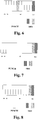
- FIG. 4 is another schematic diagram of the normal subframe (normal CP subframe) transmitting the SRSs of the example of this disclosure. As shown in FIG. 4 , the SRSs are configured in a last OFDM symbol (#6) of the fist slot of the subframe, and a last OFDM symbol (#13) of the subframe.
- FIG. 5 is a schematic diagram of an extended subframe (extended CP subframe) transmitting SRSs of the example of this disclosure. As shown in FIG. 5 , the SRSs are configured in the first OFDM symbol (#0) of the fist slot of the subframe, and a last OFDM symbol (#11) of the subframe.
- FIG. 6 is another schematic diagram of the extended subframe (extended CP subframe) transmitting the SRSs of the example of this disclosure. As shown in FIG. 6 , the SRSs are configured in a last OFDM symbol (#5) of the fist slot of the subframe, and the last OFDM symbol (#11) of the subframe.
- the SRSs are transmitted in the first or the last OFDM symbol of the first slot, which may avoid DM-RSs, RIs and ACK/NACK of uplink control information, and at the same time, relatively good channel estimation quality may be guaranteed, and may be used for using a function of automatic gain adjustment.
- the SRSs may be configured in last two OFDM symbols of a subframe.
- FIG. 7 is a schematic diagram of a normal subframe transmitting SRSs of the example of this disclosure. As shown in FIG. 7 , the SRSs are configured in last OFDM symbol but one (#12) of the subframe, and the last OFDM symbol (#13) of the subframe.
- FIG. 8 is a schematic diagram of an extended subframe transmitting SRSs of the example of this disclosure. As shown in FIG. 8 , the SRSs are configured in last OFDM symbol but one (#10) of the subframe, and the last OFDM symbol (#11) of the subframe.
- the SRSs are configured in the last two OFDM symbols of the subframe, which may be adapted to perform orthogonal cover code (OCC) operations, and may also use a repeated transmission manner.
- OCC orthogonal cover code
- the SRSs may be configured in a last OFDM symbol of a subframe, and the resources for transmitting the DM-RSs are used for transmitting the SRSs.
- two OFDM symbols transmitting DM-RSs in a subframe are used for transmitting the SRSs; or in a case of low-speed transmission (for example, in a cell scenario, UE transmits data at a speed lower than a predetermined threshold), an OFDM symbol used for transmitting DM-RSs in a subframe is used for transmitting the SRSs; that is, if a resource for transmitting DM-RSs still transmits DM-RSs for data demodulation, another resource for transmitting DM-RSs may be used for transmitting the SRSs.
- FIG. 9 is a schematic diagram of a normal subframe transmitting SRSs of the example of this disclosure.
- the SRSs are configured in a fourth OFDM symbol (#3), an eleventh OFDM symbol (#10) and a last OFDM symbol (#13) of the subframe; in which, the fourth and the eleventh OFDM symbols are originally used for transmitting DM-RSs.
- FIG. 10 is a schematic diagram of an extended subframe transmitting SRSs of the example of this disclosure. As shown in FIG. 10 , the SRSs are configured in a third OFDM symbol (#2), a ninth OFDM symbol (#8) and a last OFDM symbol (#11) of the subframe.
- the SRSs may be configured in a last OFDM symbol of a subframe, and the resources for transmitting device to device (D2D) synchronization signals are used for transmitting the SRSs.
- D2D device to device
- a second and third OFDM symbols of a first slot, or a fifth and sixth OFDM symbols of a second slot, in a normal subframe are used for transmitting the SRSs; or a first and second OFDM symbols of a first slot, or a fourth and fifth OFDM symbols of a second slot, in an extended subframe, are used for transmitting the SRSs.
- FIG. 11 is a schematic diagram of a normal subframe transmitting SRSs of the example of this disclosure. As shown in FIG. 11 , the SRSs are configured in a second (#1) and third (#2) OFDM symbols of a first slot of the subframe, and a last OFDM symbol (#13) of the subframe.
- FIG. 12 is another schematic diagram of the normal subframe transmitting the SRSs of the example of this disclosure. As shown in FIG. 12 , the SRSs are configured in a fifth (#11) and sixth (#12) OFDM symbols of a second slot of the subframe, and a last OFDM symbol (#13) of the subframe.
- FIG. 13 is a schematic diagram of an extended subframe transmitting SRSs of the example of this disclosure. As shown in FIG. 13 , the SRSs are configured in a first (#0) and second (#1) OFDM symbols of a first slot of the subframe, and a last OFDM symbol (#11) of the subframe.
- FIG. 14 is another schematic diagram of the extended subframe transmitting the SRSs of the example of this disclosure. As shown in FIG. 14 , the SRSs are configured in a fourth (#9) and fifth (#10) OFDM symbols of a second slot of the subframe, and a last OFDM symbol (#11) of the subframe.
- the SRSs may be configured in the resources transmitting D2D synchronization signals. If D2D transmission of UE and uplink transmission of other UE are multiplex together, special symbols may be aligned to reduce mutual interference. And on the other hand, advantages of design for the D2D synchronization signals may be reused, for example, automatic gain adjustment and synchronization tracking may be used.
- a base station performs uplink channel estimation based on an SRS supporting high-dimensional MU-MIMO transmitted by UE, and acquires downlink channel information by using channel reciprocity, thereby downlink reference signal overhead and feedback overhead are remarkably saved, gains brought about by large-scale antennas may be acquired, and the system capacity may be further improved.
- use of new resources may increase transmission of SRSs, and may also transmit SRSs in more time domain resources for UE with limited power, so as to solve the problem of limited power.
- a comb interval characteristic of the SRS may be enlarged according to a feature that a channel frequency selective characteristic becomes small.
- a subcarrier frequency interval i.e. a comb value
- a subcarrier frequency interval of the SRS in the frequency domain is greater than 2, such as increasing the interval to be 4.
- the number of pieces of UE multiplexed in identical resource blocks by using different comb values is increased to be 4. That is, using six subcarriers in some resource blocks to transmit SRSs by one piece of UE in an existing system may be changed into using three subcarriers in some resource blocks to transmit SRSs.
- a length of a shortest SRS sequence is 12.
- the SRS sequence will not be too short, and will not affect an interference characteristic of different pieces of UE in CDM multiplexing.
- increase of the comb interval characteristic of the SRS may support more pieces of UE.
- Example 1 further describes the SRS.
- a density of SRS sampling may be reduced according to a feature that a channel frequency selective characteristic becomes small.
- resource blocks transmitting SRSs are reduced, that is, the SRSs are only configured in a part of resource blocks.
- the number of resource blocks transmitting the SRSs may be lowered regularly. For example, for a 10M uplink bandwidth system of 50 RBs, when a cell is configured with SRS bandwidth configuration 0 and a UE is configured with SRS bandwidth indicator 0, the UE may transmit wideband SRSs in 48 RBs, and a case of limited power is prone to occur for edge UE.
- the number of PRBs transmitting the SRSs may further be lowered according to a channel characteristic; in which, for a certain piece of UE, each predetermined number of resource blocks of the SRSs is configured alternately. For example, some pieces of UE transmits the SRSs in PRB of an odd number, or some pieces of UE transmits the SRSs in PRB of an even number, or the PRBs are further divided by a certain integral multiple.
- configuration information configured in the resource blocks may be indicated via high-layer signaling, or may be defined in a standard.
- particularly divided granularities may be indicated via high-layer signaling, or may be defined in a standard.
- decrease of the density of the SRS sampling may support more pieces of UE.
- Example 1 On the basis of Example 1, the example of this disclosure further describes the SRS.
- SRSs used for measurement of downlink channel reciprocity may adopt relatively low sampling rates.
- the sampling rates of the SRSs are 10 milliseconds and more.
- the sampling rates of the SRSs are 10 milliseconds, 20 milliseconds, 40 milliseconds, 80 milliseconds, 160 milliseconds, 320 milliseconds; however, this disclosure is not limited thereto, and a particular sampling rate may be determined according to an actual situation.
- Table 6 shows a case of a UE-specific SRS periodicity T SRS and subframe offset configuration T offset , which may be applicable to an FDD system and a TDD system.
- Table 6 SRS Configuration Index I SRS SRS Periodicity T SRS (ms) SRS Subframe Offset T offset 0 - 9 10 I SRS 10 - 29 20 I sRS - 10 30 - 69 40 I SRS - 30 70 - 149 80 I sRS - 70 150 - 309 160 I sRS - 150 310 - 629 320 I SRS - 310 630 - 1023 Reserved Reserved
- Table 6 only schematically shows the case of SRS sampling rates of the example of this disclosure; however, this disclosure is not limited thereto, and particular contents may be determined according to an actual situation.
- a particular numeral value of a sampling rate may be indicated via SRS configuration applied by the reciprocity, and the indication may also include two parameters, periodicity and offset.
- Example 1 On the basis of Example 1, the example of this disclosure further describes the SRS.
- SRSs of different cells may be coordinated.
- available time frequency resources of the SRSs may be divided into two sets, for one of the sets, it may be commonly used by all cells, and for the other set, it may be shared by different cells. That is, if one of the coordinated cells obtains an opportunity of transmission, other cells do not use this SRS resource, or use this SRS resource at relatively low power.
- a base station may transmit signaling for coordinating sounding reference signals of different cells (which may be referred to as third signaling), so that when a cell transmits a sounding reference signal, other cells do not use a resource to which the sounding reference signal corresponds, or use the resource at relatively low power.
- third signaling When the coordinated cells are located between different base stations, the signaling needs to be transmitted between the base stations. And at the same time, the base stations need also to notify the UE of the SRS resource coordination result.
- the resource to which the sounding reference signal corresponds may include one of the following pieces of information or a combination thereof: information on a subframe, OFDM symbol information, comb number information, frequency interval information, resource block information, power information, and information on cyclic offset of an SRS sequence, used by the sounding reference signal; however, this disclosure is not limited thereto.
- a base station For example, for a base station, it needs to inform other base stations to mute or transmit signals at low power at a corresponding position for transmitting the SRSs. And at the same time, the base station notifies all UE to mute or transmit signals at low power at time frequency positions corresponding to the SRSs.
- coordinating SRSs of different cells may reduce mutual interference between the SRSs.
- Example 1 On the basis of Example 1, the example of this disclosure further describes the SRS.
- the base station in order to overcome an effect of unequal numbers of antennas of the UE for transmission and reception on channel reciprocity, the base station needs to know whether the UE has an ability to transmit and receive information by using the same numbers of antennas, and this ability may be reported via UE ability signaling.
- the base station may receive the UE ability signaling reported by the UE.
- the UE ability signaling may include information on the number of antennas and/or information on an ability of the UE, the information on an ability of the UE being used to indicate whether the UE has an ability to transmit and receive information by using the same numbers of antennas.
- the information on the number of antennas may be information on the number of receiving antennas; however, this disclosure is not limited thereto.
- the base station When the base station knows that the UE does not have such an ability, it cannot use such type of SRSs for performing downlink channel estimation.
- the base station may configure the UE via specific signaling to transmit SRSs at corresponding transmitting antennas. Resources defined in the standards may be used to transmit the SRSs, or newly-added resources may be used to transmit the SRSs.
- the UE transmits the SRSs according to the configuration by the base station, or the UE transmits the SRSs according to defined actions and the base station may receive the SRSs according to such a definition.
- the SRSs may be cycled by the UE in the time domain resources and transmitted.
- actions of the UE may be defined in the standards, and the base station may adopt a corresponding receiving method after receiving the UE ability signaling.
- 2Tx may be cycled for transmission of the SRSs in the time domain resources, that is, the SRSs are transmitted at different 2Tx antennas at different times.
- a symbol time for transmitting the SRSs must satisfy a time of antenna switch, such as at an interval of one or two OFDM symbols.
- the base station may configure the UE with multiple (two or more) sets of SRSs, so that the UE transmits the multiple sets of SRSs by using different antenna groups.
- Resources for transmitting the multiple sets of SRSs are divided in the time domain, such as using resources of different OFDM symbols or subframes to transmit the multiple sets of SRSs, respectively, thereby achieving switch of transmission of different groups of antennas.
- a time interval for transmitting the multiple sets of SRSs must satisfy a time of antenna switch, such as at an interval of one or two OFDM symbols.
- An example of this disclosure provides a downlink channel estimation apparatus based on an SRS, which is configured in a base station.
- the example of this disclosure corresponds to the downlink channel estimation method based on an SRS described in examples 1-7, with identical contents being not going to be described herein any further.
- FIG. 15 is a schematic diagram of the downlink channel estimation apparatus based on an SRS of an example of this disclosure. As shown in FIG. 15 , the apparatus 1500 includes:
- the apparatus 1500 may further include: a signaling transmitting unit 1504 configured to transmit UE-specific first signaling and/or cell-specific second signaling to the UE; wherein the first signaling contains SRS configuration information for the UE, and the second signaling contains SRS configuration information for the cell.
- a signaling transmitting unit 1504 configured to transmit UE-specific first signaling and/or cell-specific second signaling to the UE; wherein the first signaling contains SRS configuration information for the UE, and the second signaling contains SRS configuration information for the cell.
- This example further provides a base station, which is configured with the downlink channel estimation apparatus 1500 based on an SRS as described above.
- FIG. 16 is a schematic diagram of a structure of the base station of the example of this disclosure.
- the base station 1600 may include a central processing unit (CPU) 200 and a memory 210, the memory 210 being coupled to the central processing unit 200.
- the memory 210 may store various data, and furthermore, it may store a program for information processing, and execute the program under control of the central processing unit 200, so as to receive various information transmitted by the UE, and transmit request information to the UE.
- the central processing unit 200 may be configured to carry out the functions of the downlink channel estimation apparatus 1500.
- the base station 1600 may carry out the downlink channel estimation method described in examples 1-7.
- the base station 1600 may include a transceiver 220, and an antenna 230, etc. Functions of the above components are similar to those in the relevant art, and shall not be described herein any further. It should be appreciated that the base station 1600 does not necessarily include all the parts shown in FIG. 16 , and furthermore, the base station 1600 may include parts not shown in FIG. 16 , and the relevant art may be referred to.
- the base station performs uplink channel estimation based on an SRS supporting high-dimensional MU-MIMO transmitted by UE, and acquires downlink channel information by using channel reciprocity, thereby downlink reference signal overhead and feedback overhead can be remarkably reduced, gains brought about by large-scale antennas can be acquired, and the system capacity can be further improved.
- FIG. 17 is a schematic diagram of a structure of the communications system of the example of this disclosure. As shown in FIG. 17 , the communications system 1700 includes:
- An example of the present disclosure provides a computer readable program code, which, when executed in a base station, will cause a computer unit to carry out the downlink channel estimation method based on an SRS described in examples 1-7 in the base station.
- An example of the present disclosure provides a computer readable medium, including a computer readable program code, which will cause a computer unit to carry out the downlink channel estimation method based on an SRS described in examples 1-7 in a base station.
- the above apparatuses and methods of the present disclosure may be implemented by hardware, or by hardware in combination with software.
- the present disclosure relates to such a computer-readable program that when the program is executed by a logic device, the logic device is enabled to carry out the apparatus or components as described above, or to carry out the methods or steps as described above.
- the present disclosure also relates to a storage medium for storing the above program, such as a hard disk, a floppy disk, a CD, a DVD, and a flash memory, etc.
- One or more functional blocks and/or one or more combinations of the functional blocks in the drawings may be realized as a universal processor, a digital signal processor (DSP), an application-specific integrated circuit (ASIC), a field programmable gate array (FPGA) or other programmable logic devices, discrete gate or transistor logic devices, discrete hardware component or any appropriate combinations thereof. And they may also be realized as a combination of computing equipment, such as a combination of a DSP and a microprocessor, multiple processors, one or more microprocessors in communication combination with a DSP, or any other such configuration.
- DSP digital signal processor
- ASIC application-specific integrated circuit
- FPGA field programmable gate array
Description
- This disclosure relates to the field of communications technologies, and in particular to a downlink channel estimation method and apparatus based on a sounding reference signal (SRS) in a high-dimensional multiple user multiple input multiple output (MU-MIMO) system, and a communications system.
- With the development of antenna technologies, a two-dimensional (2D) active antenna array may be arranged at a transmitting device, which forms three-dimensional (3D) beams through flexible weighting of antenna coefficients. The three-dimensional multi-antenna technology may improve antenna gains, reduce beam widths and reduce interference on the one hand, and on the other hand, it may improve multiplexing efficiency of the system by spatially multiplexing more users. Hence, the three-dimensional multi-antenna technology may remarkably improve the transmission efficiency and reliability of the system, and is a hot candidate technology for future mobile communications systems.
- Relative to the two-dimensional multi-antenna technology, the three-dimensional multi-antenna technology has a better spatial separation characteristic, and is able to support more users to multiplex transmission.
FIG. 1 is a schematic diagram of multiple user multiple input multiple output (MU-MIMO) in a 3D MIMO system. As shown inFIG. 1 , a vertical dimension is added to the 3D multi-antenna system, and the number of dimensions supporting MU-MIMO in the system may further be increased. - And on the other hand, a current system, such as a frequency division duplex (FDD) system, usually adopts a reference signal to perform downlink channel estimation. That is, a base station (such as an eNB) transmits a reference signal, such as a common reference signal (CRS), or a channel state information reference signal (CSI-RS), to user equipment (UE), and the UE measures the reference signal and feeds back information on a channel, such as a rank indicator (RI)/a precoding matrix indicator (PMI)/a channel quality indicator (CQI), via an uplink channel.
- It should be appreciated that the above description of the background is merely provided for clear and complete explanation of this disclosure and for easy understanding by those skilled in the art. And it should not be understood that the above technical solution is known to those skilled in the art as it is described in the background of this disclosure.
-
CN102104404A discloses a multi-user multiple input multiple output (MU-MIMO) transmission method in a wireless communication system, a base station and a user terminal. The method comprises the following steps that: the base station receives detection pilot frequency SRS of N users to perform channel estimation and acquires downlink channel information according to the channel estimation result and channel reciprocity of the system, wherein N is more than 1; the base station performs quick response (QR) decomposition on the downlink channel information, acquires a multi-user beamforming (MU-BF) matrix P (i) of the ith user from a Q matrix acquired through decomposition, and acquires a downlink single-user beamforming (SU-BF) matrix V (i) of the ith user further, wherein i=l, ...,N; and the base station performs beamforming processing on transmitting data of the ith user according to the MU-BF matrix P (i) and the SU-BF matrix V (i). The method and equipment acquire beamforming matrixes for uplink and downlink MU-MIMO transmission by means of the channel reciprocity of the system and the QR decomposition. - However, it was found by the inventors that in a high-dimensional MU-MIMO (which may be referred to as 3D MIMO or massive MIMO) system, as the increase of the number of antennas, reference signal overhead and feedback overhead needed by a base station in acquiring downlink channel information are remarkably increased, gains brought about by large-scale antennas cannot be acquired, and the system capacity cannot be further improved.
- Examples of this disclosure provide a downlink channel estimation method and apparatus and a communications system, in which uplink channel estimation is performed based on an SRS supporting high-dimensional MIMO transmitted by UE, and downlink channel information is acquired by using channel reciprocity, thereby downlink reference signal overhead and feedback overhead are remarkably saved.
- Aspects of the invention are defined by the appended claims to which reference should be made.
- Advantages of the examples of this disclosure exists in that a base station performs uplink channel estimation based on an SRS supporting high-dimensional MU-MIMO transmitted by UE, and acquires downlink channel information by using channel reciprocity. Thereby downlink reference signal overhead and feedback overhead are remarkably saved, gains brought about by large-scale antennas are acquired, and the system capacity is further improved.
- With reference to the following description and drawings, the particular examples of this disclosure are disclosed in detail, and the principle of this disclosure and the manners of use are indicated. It should be understood that the scope of the examples of this disclosure is not limited thereto. The examples of this disclosure contain many alternations and modifications within the scope of the terms of the appended claims.
- Features that are described and/or illustrated with respect to one example may be used in the same way or in a similar way in one or more other examples and/or in combination with or instead of the features of the other examples.
- It should be emphasized that the term "comprise/include" when used in this specification is taken to specify the presence of stated features, integers, steps or components but does not preclude the presence or addition of one or more other features, integers, steps, components or groups thereof.
- Many aspects of the disclosure can be better understood with reference to the following drawings. The components in the drawings are not necessarily to scale, emphasis instead being placed upon clearly illustrating the principles of this disclosure. To facilitate illustrating and describing some parts of the disclosure, corresponding portions of the drawings may be exaggerated or reduced.
- Elements and features depicted in one drawing or example of the disclosure may be combined with elements and features depicted in one or more additional drawings or examples. Moreover, in the drawings, like reference numerals designate corresponding parts throughout the several views and may be used to designate like or similar parts in more than one example.
-
FIG. 1 is a schematic diagram of MU-MIMO in a 3D MIMO system; -
FIG. 2 is a flowchart of the downlink channel estimation method based on an SRS of an example of this disclosure; -
FIG. 3 is a schematic diagram of a normal subframe transmitting SRSs of an example of this disclosure; -
FIG. 4 is another schematic diagram of the normal subframe transmitting the SRSs of the example of this disclosure; -
FIG. 5 is a schematic diagram of an extended subframe transmitting SRSs of the example of this disclosure; -
FIG. 6 is another schematic diagram of the extended subframe transmitting the SRSs of the example of this disclosure; -
FIG. 7 is a schematic diagram of a normal subframe transmitting SRSs of the example of this disclosure; -
FIG. 8 is a schematic diagram of an extended subframe transmitting SRSs of the example of this disclosure; -
FIG. 9 is a schematic diagram of a normal subframe transmitting SRSs of the example of this disclosure; -
FIG. 10 is a schematic diagram of an extended subframe transmitting SRSs of the example of this disclosure; -
FIG. 11 is a schematic diagram of a normal subframe transmitting SRSs of the example of this disclosure; -
FIG. 12 is another schematic diagram of the normal subframe transmitting the SRSs of the example of this disclosure; -
FIG. 13 is a schematic diagram of an extended subframe transmitting SRSs of the example of this disclosure; -
FIG. 14 is another schematic diagram of the extended subframe transmitting the SRSs of the example of this disclosure; -
FIG. 15 is a schematic diagram of the downlink channel estimation apparatus based on an SRS of an example of this disclosure; -
FIG. 16 is a schematic diagram of a structure of a base station of an example of this disclosure; and -
FIG. 17 is a schematic diagram of a structure of the communications system of an example of this disclosure. - These and further aspects and features of this disclosure will be apparent with reference to the following description and attached drawings. In the description and drawings, particular examples of the disclosure have been disclosed in detail as being indicative of some of the ways in which the principles of the disclosure may be employed, but it is understood that the disclosure is not limited correspondingly in scope. Rather, the disclosure includes all changes and modifications coming within the terms of the appended claims.
- Currently, an SRS is mainly used for measurement of an uplink channel, and for supporting uplink scheduling of UE. A time position of a cell SRS subframe may be determined via a high-layer configuration period and a transmission offset. Table 1 shows SRS subframe configuration in an FDD system, and Table 2 shows SRS subframe configuration in a time division duplex (TDD) system.
Table 1 srs-SubframeConfig Binary Configuration period T SFC (subframes) Transmission offset ΔSFC (subframes) 0 0000 1 {0} 1 0001 2 {0} 2 0010 2 {1} 3 0011 5 {0} 4 0100 5 {1} 5 0101 5 {2} 6 0110 5 {3} 7 0111 5 {0,1} 8 1000 5 {2,3} 9 1001 10 {0} 10 1010 10 {1} 11 1011 10 {2} 12 1100 10 {3} 13 1101 10 {0,1,2,3,4,6,8} 14 1110 10 {0,1,2,3,4,5,6,8} 15 1111 Reserved Reserved Table 2 srs-SubframeConfig Binary Configuration period T SFC (subframes) Transmission offset ΔSFC (subframes) 0 0000 5 {1} 1 0001 5 {1, 2} 2 0010 5 {1, 3} 3 0011 5 {1, 4} 4 0100 5 {1, 2, 3} 5 0101 5 {1, 2, 4} 6 0110 5 {1, 3, 4} 7 0111 5 {1, 2, 3, 4} 8 1000 10 {1, 2, 6} 9 1001 10 {1, 3, 6} 10 1010 10 {1, 6, 7} 11 1011 10 {1, 2, 6, 8} 12 1100 10 {1, 3, 6, 9} 13 1101 10 {1, 4, 6, 7} 14 1110 Reserved Reserved 15 1111 Reserved Reserved - Furthermore, a transmission time of the UE may be determined by using a subframe period and an offset. Table 3 shows a UE-specific SRS periodicity TSRS and subframe offset configuration Toffset triggering type 0 in an FDD system, and Table 4 shows a UE-specific SRS periodicity TSRS and subframe offset configuration Toffset triggering type 0 in a TDD system.
Table 3 SRS Configuration Index ISRS SRS Periodicity TSRS (ms) SRS Subframe Offset Toffset 0 - 1 2 ISRS 2 - 6 5 ISRS - 2 7 - 16 10 ISRS - 7 17 - 36 20 ISRS - 17 37 - 76 40 ISRS - 37 77 - 156 80 ISRS - 77 157 - 316 160 ISRS -157 317 - 636 320 ISRS - 317 637 - 1023 Reserved Reserved Table 4 SRS Configuration Index ISRS SRS Periodicity TSRS (ms) SRS Subframe Offset T offset0 2 0, 1 1 2 0,2 2 2 1,2 3 2 0,3 4 2 1,3 5 2 0,4 6 2 1,4 7 2 2,3 8 2 2,4 9 2 3,4 10 - 14 5 ISRS - 10 15 - 24 10 ISRS - 15 25 - 44 20 ISRS - 25 45 - 84 40 ISRS - 45 85 - 164 80 ISRS - 85 165 - 324 160 ISRS - 165 325 - 644 320 ISRS - 325 645 - 1023 Reserved reserved - A physical layer configures each cell with eight types of different SRS bandwidth configuration and configures each piece of UE with four bandwidth options by using high-layer signaling, and completes indication of a UE SRS bandwidth via a two-stage structure. Table 5 gives all possible SRS bandwidth configuration and bandwidth options, i.e. m SRS, b and Nb , where, b = 0,1,2,3, when an uplink bandwidth is 40-60 RB

Table 5 SRS bandwidth configuration C SRS SRS bandwidth B SRS = 0 SRS bandwidth B SRS = 1 SRS bandwidth B SRS = 2 SRS bandwidth B SRS = 3 m SRS,0 N 0 m SRS,1 N 1 m SRS,2 N 2 m SRS,3 N 3 0 48 1 24 2 12 2 4 3 1 48 1 16 3 8 2 4 2 2 40 1 20 2 4 5 4 1 3 36 1 12 3 4 3 4 1 4 32 1 16 2 8 2 4 2 5 24 1 4 6 4 1 4 1 6 20 1 4 5 4 1 4 1 7 16 1 4 4 4 1 4 1 - Furthermore, a position of a starting point of a frequency is determined by radio resource control (RRC) signaling. An SRS sequence is a Zadoff-Chu sequence, and is determined jointly by the number of groups of sequences of physical uplink control channel (PUCCH), the number of groups of base sequences and cyclic shift identifiers.
- In mapping of a sequence to a physical resource, an SRS adopts a frequency interval of two subcarriers, forming a "comb" frequency domain structure. SRSs of different UE are multiplexed by frequency division multiplexing (FDM) (i.e. different comb values), time division multiplexing (TDM) (i.e. different subframes) and code division multiplexing (CDM); the CDM is carried out by cyclic shifts (at most eight) of the base sequences.
- An SRS is transmitted in a last symbol of a normal uplink subframe. In a TDD frame structure, in a case where a length of the UpPTS is of two symbols, the two symbols may both be configured for the SRS transmission. When the UpPTS has an single-carrier frequency division multiple access (SC-FDMA) symbol, the symbol may be used for the SRS transmission; and when the UpPTS has two SC-FDMA symbols, they may both be used for the SRS transmission, and may be allocated for the same UE.
- When channel quality is relatively worse, use of a narrow-band SRS may improve channel quality of a receiving device, hence, a hopping method needs to be used to acquire channel information on more bands. At present, a periodic SRS supports hopping transmission, and an aperiodic SRS does not support hopping transmission.
- On the other hand, in a current system, such as a time division duplex (TDD) system, uplink and downlink channels have reciprocity to some extent, and a base station may acquire information on an uplink channel by measuring an SRS transmitted by UE, and then obtain information on a downlink channel by using a calibration technology.
- In this example, in the 3D MIMO or massive MIMO system, information on a downlink channel may be acquired based on an SRS supporting high-dimensional MU-MIMO and by using channel reciprocity, which may remarkably save downlink reference signal overhead and feedback overhead, acquire gains brought about by large-scale antennas, and further improve the system capacity. Examples of this disclosure shall be described below in detail.
- An example of this disclosure provides a downlink channel estimation method based on an SRS.
FIG. 2 is a flowchart of the downlink channel estimation method based on an SRS of the example of this disclosure. As shown inFIG. 2 , the method includes: - step 201: a base station receives an SRS transmitted by UE, the SRS being used for downlink channel estimation and supporting high-dimensional MU-MIMO;
- step 202: the base station performs uplink channel estimation according to the SRS; and
- step 203: the base station acquires downlink channel information according to uplink channel information obtained through the uplink channel estimation.
- In this example, this method is applicable to a high-dimensional MU-MIMO system; in which, following defects exist in the SRS: the number of pieces of UE supported by the high-dimensional MU-MIMO system will be remarkably increased, which will result in insufficiency of a capacity of the SRS; in configuring a wideband SRS for edge UE, transmission power is relatively large, and a case of limited power will occur in the UE; and if the number of antennas for transmission at the UE side is different from that of antennas for reception at the UE side, use of uplink and downlink reciprocity will be affected.
- Furthermore, in a large-scale MIMO system, following characteristics will be presented in a channel:
- (1) in performing beamforming transmission, a time-varying characteristic of the channel is relatively small; this is because as increase of the number of antennas, a spatial resolution of the channel will be increased; and if the UE moves at a relatively large speed, a spatial direction from a base station to the UE varies relatively fast, which needs the UE to feed back at a relatively large speed, resulting in very large feedback overhead; otherwise, a problem of robustness will occur in the transmission; hence, time variation of the channel in a typical application scenario of large-scale antennas is small;
- (2) as increase of the number of antennas, sizes of the antennas are limited in use; in order to guarantee the sizes of the antennas, large-scale antennas are generally applied at a higher band, such as 5 GHz; at this band, a wavelength is relatively small, the number of scatters near the UE will be increased, and when the number of antennas is relatively large, a frequency selective characteristic of the channel will become relatively stable; and on the other hand, identical system bandwidths become transmission of a relatively narrow band at a high carrier frequency; hence, a frequency selective characteristic of the system will be relatively weakened; and
- (3) as increase of the number of antennas, a spatial resolution of the channel will be increased, and information on a spatial orientation of the channel will become almost quasi-orthogonal.
- In order to solve the above problems, the examples of this disclosure propose an enhancement scheme, and use an SRS supporting high-dimensional MU-MIMO; in which, the SRS is used for downlink channel estimation. The SRS of the examples of this disclosure may be deemed as enhancing an existing SRS, may be deemed as a new type of SRS, and may be referred to as an SRS of type 2.
- As shown in
FIG. 2 , the method may further include:
step 2001: the base station configures the UE a resource for transmitting the SRS. - For example, the base station may transmit UE-specific first signaling and/or cell-specific second signaling to the UE; and the first signaling contains SRS configuration information on the UE, and the second signaling contains SRS configuration information on the cell.
- The SRS configuration information on the cell may be as described in Example 2 below, and a configuration signaling of the resource for transmitting the SRS (the second signaling) may include a time domain subframe periodicity, offset and used orthogonal frequency division multiplexing (OFDM) symbol(s); however, this disclosure is not limited thereto.
- For each piece of UE, examples 2-7 describe possible resources for transmitting SRSs, and a part of the resources may be used for transmitting the SRSs, each piece of configuration signaling of the resource for transmitting the SRSs (the first signaling) may include a time domain subframe periodicity, offset and used OFDM symbol(s), and a frequency carrier starting point indicator, the number of combs and physical resource blocks, as well as cyclic offset of an SRS sequence; however, this disclosure is not limited thereto.
- In this example, the base station may perform uplink channel estimation based on an SRS transmitted by the UE, and any existing uplink channel estimation method may be used. Then information on the downlink channel may be obtained by using channel reciprocity (such as by means of calibration technology). Hence, downlink reference signal overheads and feedback overheads can be remarkably reduced, gain brought by large-scale antennas is obtained, and the system capacity can be further improved.
- On the basis of Example 1, the example of this disclosure further describes the SRS. In this example, increasing available resources for SRSs is an effective method for solving a problem that an SRS capacity and power are limited. New resources may be used for transmitting SRSs of increased UE, and SRSs may also be transmitted in more time domain resources for UE with limited power, so as to lower its transmission power, and solve the problem of limited power.
- In this example, in addition to the resources for transmitting SRSs in the standards, new resources are used for transmitting SRSs. Taken into account that uplink transmission uses single-carrier FDMA, the whole symbols are used for transmitting the SRSs. In order to keep a unified design of FDD and TDD, the following possible OFDM symbols may be used for SRS transmission. In an LTE system, in a normal cyclic prefix (CP) subframe, symbols 3 and 10 are used for transmitting demodulation reference signals (DM-RSs),
symbols 2 and 11 are possibly used for transmitting ACK/NACK, andsymbols 1 and 12 are possibly used for RI transmission. In an extended subframe, the similarly specified resources are used for transmitting DM-RSs, ACK/NACK and RIs. When new SRS resources are added, it needs to take into account that these resources should be avoided, so as to reduce influence on legacy UE. - In an implementation, the SRSs may be configured in a last OFDM symbol of a subframe, and a first or last OFDM symbol of a first slot of the subframe.
-
FIG. 3 is a schematic diagram of a normal subframe (normal CP subframe) transmitting SRSs of the example of this disclosure. As shown inFIG. 3 , the SRSs are configured in a first OFDM symbol (#0) of a fist slot of the subframe, and a last OFDM symbol (#13) of the subframe. -
FIG. 4 is another schematic diagram of the normal subframe (normal CP subframe) transmitting the SRSs of the example of this disclosure. As shown inFIG. 4 , the SRSs are configured in a last OFDM symbol (#6) of the fist slot of the subframe, and a last OFDM symbol (#13) of the subframe. -
FIG. 5 is a schematic diagram of an extended subframe (extended CP subframe) transmitting SRSs of the example of this disclosure. As shown inFIG. 5 , the SRSs are configured in the first OFDM symbol (#0) of the fist slot of the subframe, and a last OFDM symbol (#11) of the subframe. -
FIG. 6 is another schematic diagram of the extended subframe (extended CP subframe) transmitting the SRSs of the example of this disclosure. As shown inFIG. 6 , the SRSs are configured in a last OFDM symbol (#5) of the fist slot of the subframe, and the last OFDM symbol (#11) of the subframe. - In this implementation, the SRSs are transmitted in the first or the last OFDM symbol of the first slot, which may avoid DM-RSs, RIs and ACK/NACK of uplink control information, and at the same time, relatively good channel estimation quality may be guaranteed, and may be used for using a function of automatic gain adjustment.
- In another implementation, the SRSs may be configured in last two OFDM symbols of a subframe.
-
FIG. 7 is a schematic diagram of a normal subframe transmitting SRSs of the example of this disclosure. As shown inFIG. 7 , the SRSs are configured in last OFDM symbol but one (#12) of the subframe, and the last OFDM symbol (#13) of the subframe. -
FIG. 8 is a schematic diagram of an extended subframe transmitting SRSs of the example of this disclosure. As shown inFIG. 8 , the SRSs are configured in last OFDM symbol but one (#10) of the subframe, and the last OFDM symbol (#11) of the subframe. - In this implementation, the SRSs are configured in the last two OFDM symbols of the subframe, which may be adapted to perform orthogonal cover code (OCC) operations, and may also use a repeated transmission manner.
- In another implementation, the SRSs may be configured in a last OFDM symbol of a subframe, and the resources for transmitting the DM-RSs are used for transmitting the SRSs.
- For example, in a case of no data transmission (for example, the system has no data transmission in some resources), two OFDM symbols transmitting DM-RSs in a subframe are used for transmitting the SRSs; or in a case of low-speed transmission (for example, in a cell scenario, UE transmits data at a speed lower than a predetermined threshold), an OFDM symbol used for transmitting DM-RSs in a subframe is used for transmitting the SRSs; that is, if a resource for transmitting DM-RSs still transmits DM-RSs for data demodulation, another resource for transmitting DM-RSs may be used for transmitting the SRSs.
-
FIG. 9 is a schematic diagram of a normal subframe transmitting SRSs of the example of this disclosure. As shown inFIG. 9 , the SRSs are configured in a fourth OFDM symbol (#3), an eleventh OFDM symbol (#10) and a last OFDM symbol (#13) of the subframe; in which, the fourth and the eleventh OFDM symbols are originally used for transmitting DM-RSs. -
FIG. 10 is a schematic diagram of an extended subframe transmitting SRSs of the example of this disclosure. As shown inFIG. 10 , the SRSs are configured in a third OFDM symbol (#2), a ninth OFDM symbol (#8) and a last OFDM symbol (#11) of the subframe. - In another implementation, the SRSs may be configured in a last OFDM symbol of a subframe, and the resources for transmitting device to device (D2D) synchronization signals are used for transmitting the SRSs.
- For example, a second and third OFDM symbols of a first slot, or a fifth and sixth OFDM symbols of a second slot, in a normal subframe, are used for transmitting the SRSs; or a first and second OFDM symbols of a first slot, or a fourth and fifth OFDM symbols of a second slot, in an extended subframe, are used for transmitting the SRSs.
-
FIG. 11 is a schematic diagram of a normal subframe transmitting SRSs of the example of this disclosure. As shown inFIG. 11 , the SRSs are configured in a second (#1) and third (#2) OFDM symbols of a first slot of the subframe, and a last OFDM symbol (#13) of the subframe. -
FIG. 12 is another schematic diagram of the normal subframe transmitting the SRSs of the example of this disclosure. As shown inFIG. 12 , the SRSs are configured in a fifth (#11) and sixth (#12) OFDM symbols of a second slot of the subframe, and a last OFDM symbol (#13) of the subframe. -
FIG. 13 is a schematic diagram of an extended subframe transmitting SRSs of the example of this disclosure. As shown inFIG. 13 , the SRSs are configured in a first (#0) and second (#1) OFDM symbols of a first slot of the subframe, and a last OFDM symbol (#11) of the subframe. -
FIG. 14 is another schematic diagram of the extended subframe transmitting the SRSs of the example of this disclosure. As shown inFIG. 14 , the SRSs are configured in a fourth (#9) and fifth (#10) OFDM symbols of a second slot of the subframe, and a last OFDM symbol (#11) of the subframe. - In this implementation, the SRSs may be configured in the resources transmitting D2D synchronization signals. If D2D transmission of UE and uplink transmission of other UE are multiplex together, special symbols may be aligned to reduce mutual interference. And on the other hand, advantages of design for the D2D synchronization signals may be reused, for example, automatic gain adjustment and synchronization tracking may be used.
- It can be seen from the above example that a base station performs uplink channel estimation based on an SRS supporting high-dimensional MU-MIMO transmitted by UE, and acquires downlink channel information by using channel reciprocity, thereby downlink reference signal overhead and feedback overhead are remarkably saved, gains brought about by large-scale antennas may be acquired, and the system capacity may be further improved.
- Furthermore, use of new resources may increase transmission of SRSs, and may also transmit SRSs in more time domain resources for UE with limited power, so as to solve the problem of limited power.
- On the basis of Example 1, the example of this disclosure further describes the SRS. In this example, a comb interval characteristic of the SRS may be enlarged according to a feature that a channel frequency selective characteristic becomes small. In the existing standards, a subcarrier frequency interval (i.e. a comb value) is 2.
- In this example, a subcarrier frequency interval of the SRS in the frequency domain is greater than 2, such as increasing the interval to be 4. Hence, the number of pieces of UE multiplexed in identical resource blocks by using different comb values is increased to be 4. That is, using six subcarriers in some resource blocks to transmit SRSs by one piece of UE in an existing system may be changed into using three subcarriers in some resource blocks to transmit SRSs.
- According to a characteristic that the number of existing sounding resource blocks is 4, a length of a shortest SRS sequence is 12. Hence, the SRS sequence will not be too short, and will not affect an interference characteristic of different pieces of UE in CDM multiplexing.
- It can be seen from the above example that increase of the comb interval characteristic of the SRS may support more pieces of UE.
- On the basis of Example 1, the example of this disclosure further describes the SRS. In this example, a density of SRS sampling may be reduced according to a feature that a channel frequency selective characteristic becomes small. In this example, resource blocks transmitting SRSs are reduced, that is, the SRSs are only configured in a part of resource blocks.
- On the premise of a previous tree SRS structure, in resource blocks to which each sampling width corresponds, the number of resource blocks transmitting the SRSs may be lowered regularly. For example, for a 10M uplink bandwidth system of 50 RBs, when a cell is configured with
SRS bandwidth configuration 0 and a UE is configured withSRS bandwidth indicator 0, the UE may transmit wideband SRSs in 48 RBs, and a case of limited power is prone to occur for edge UE. - In addition to changing the SRS bandwidth indicator configured for UE, the number of PRBs transmitting the SRSs may further be lowered according to a channel characteristic; in which, for a certain piece of UE, each predetermined number of resource blocks of the SRSs is configured alternately. For example, some pieces of UE transmits the SRSs in PRB of an odd number, or some pieces of UE transmits the SRSs in PRB of an even number, or the PRBs are further divided by a certain integral multiple.
- In this example, configuration information configured in the resource blocks may be indicated via high-layer signaling, or may be defined in a standard. For example, for the PRBs transmitting the SRSs, particularly divided granularities may be indicated via high-layer signaling, or may be defined in a standard.
- It can be seen from the above example that decrease of the density of the SRS sampling may support more pieces of UE.
- On the basis of Example 1, the example of this disclosure further describes the SRS. In this example, taking a characteristic that a channel changes slowly into account, SRSs used for measurement of downlink channel reciprocity may adopt relatively low sampling rates. In this example, the sampling rates of the SRSs are 10 milliseconds and more.
- For example, the sampling rates of the SRSs are 10 milliseconds, 20 milliseconds, 40 milliseconds, 80 milliseconds, 160 milliseconds, 320 milliseconds; however, this disclosure is not limited thereto, and a particular sampling rate may be determined according to an actual situation.
- Table 6 shows a case of a UE-specific SRS periodicity TSRS and subframe offset configuration Toffset, which may be applicable to an FDD system and a TDD system.
Table 6 SRS Configuration Index ISRS SRS Periodicity TSRS (ms) SRS Subframe Offset Toffset 0 - 9 10 ISRS 10 - 29 20 IsRS - 10 30 - 69 40 ISRS - 30 70 - 149 80 IsRS - 70 150 - 309 160 IsRS - 150 310 - 629 320 ISRS - 310 630 - 1023 Reserved Reserved - It should be appreciated that Table 6 only schematically shows the case of SRS sampling rates of the example of this disclosure; however, this disclosure is not limited thereto, and particular contents may be determined according to an actual situation.
- Furthermore, a particular numeral value of a sampling rate may be indicated via SRS configuration applied by the reciprocity, and the indication may also include two parameters, periodicity and offset.
- It can be seen from the above example that use of relatively low sampling rates of the SRS may support more pieces of UE.
- On the basis of Example 1, the example of this disclosure further describes the SRS. In this example, in order to lower mutual interference between SRSs, SRSs of different cells may be coordinated.
- In this example, available time frequency resources of the SRSs may be divided into two sets, for one of the sets, it may be commonly used by all cells, and for the other set, it may be shared by different cells. That is, if one of the coordinated cells obtains an opportunity of transmission, other cells do not use this SRS resource, or use this SRS resource at relatively low power.
- In this example, a base station may transmit signaling for coordinating sounding reference signals of different cells (which may be referred to as third signaling), so that when a cell transmits a sounding reference signal, other cells do not use a resource to which the sounding reference signal corresponds, or use the resource at relatively low power. When the coordinated cells are located between different base stations, the signaling needs to be transmitted between the base stations. And at the same time, the base stations need also to notify the UE of the SRS resource coordination result.
- For example, the resource to which the sounding reference signal corresponds may include one of the following pieces of information or a combination thereof: information on a subframe, OFDM symbol information, comb number information, frequency interval information, resource block information, power information, and information on cyclic offset of an SRS sequence, used by the sounding reference signal; however, this disclosure is not limited thereto.
- For example, for a base station, it needs to inform other base stations to mute or transmit signals at low power at a corresponding position for transmitting the SRSs. And at the same time, the base station notifies all UE to mute or transmit signals at low power at time frequency positions corresponding to the SRSs.
- It can be seen from the above example that coordinating SRSs of different cells may reduce mutual interference between the SRSs.
- On the basis of Example 1, the example of this disclosure further describes the SRS. In this example, in order to overcome an effect of unequal numbers of antennas of the UE for transmission and reception on channel reciprocity, the base station needs to know whether the UE has an ability to transmit and receive information by using the same numbers of antennas, and this ability may be reported via UE ability signaling.
- In this example, the base station may receive the UE ability signaling reported by the UE. The UE ability signaling may include information on the number of antennas and/or information on an ability of the UE, the information on an ability of the UE being used to indicate whether the UE has an ability to transmit and receive information by using the same numbers of antennas. The information on the number of antennas may be information on the number of receiving antennas; however, this disclosure is not limited thereto.
- When the base station knows that the UE does not have such an ability, it cannot use such type of SRSs for performing downlink channel estimation.
- And when the base station knows that the UE has such an ability, the base station may configure the UE via specific signaling to transmit SRSs at corresponding transmitting antennas. Resources defined in the standards may be used to transmit the SRSs, or newly-added resources may be used to transmit the SRSs. The UE transmits the SRSs according to the configuration by the base station, or the UE transmits the SRSs according to defined actions and the base station may receive the SRSs according to such a definition.
- In a manner, the SRSs may be cycled by the UE in the time domain resources and transmitted. For example, actions of the UE may be defined in the standards, and the base station may adopt a corresponding receiving method after receiving the UE ability signaling. For example, for a 2Tx/4Rx antenna system, 2Tx may be cycled for transmission of the SRSs in the time domain resources, that is, the SRSs are transmitted at different 2Tx antennas at different times. In order to ensure achievement of the antenna cycle, a symbol time for transmitting the SRSs must satisfy a time of antenna switch, such as at an interval of one or two OFDM symbols.
- In another manner, the base station may configure the UE with multiple (two or more) sets of SRSs, so that the UE transmits the multiple sets of SRSs by using different antenna groups. Resources for transmitting the multiple sets of SRSs are divided in the time domain, such as using resources of different OFDM symbols or subframes to transmit the multiple sets of SRSs, respectively, thereby achieving switch of transmission of different groups of antennas. In order to ensure achievement of the antenna cycle, a time interval for transmitting the multiple sets of SRSs must satisfy a time of antenna switch, such as at an interval of one or two OFDM symbols.
- It can be seen from the above example that by reporting the UE ability, the effect of unequal numbers of antennas of the UE for transmission and reception on channel reciprocity may be overcome.
- An example of this disclosure provides a downlink channel estimation apparatus based on an SRS, which is configured in a base station. The example of this disclosure corresponds to the downlink channel estimation method based on an SRS described in examples 1-7, with identical contents being not going to be described herein any further.
-
FIG. 15 is a schematic diagram of the downlink channel estimation apparatus based on an SRS of an example of this disclosure. As shown inFIG. 15 , theapparatus 1500 includes: - a reference
signal receiving unit 1501 configured to receive an SRS transmitted by UE, the SRS being used for downlink channel estimation and supporting high-dimensional MU-MIMO; - an uplink
channel estimating unit 1502 configured to perform uplink channel estimation according to the SRS; and - a downlink channel
information acquiring unit 1503 configured to acquire downlink channel information according to uplink channel information obtained through the uplink channel estimation. - In this example, particular contents of resources for transmitting the SRS are as described in examples 1-7, and for one piece of UE, a part of the resources may be used.
- As shown in
FIG. 15 , theapparatus 1500 may further include:
asignaling transmitting unit 1504 configured to transmit UE-specific first signaling and/or cell-specific second signaling to the UE; wherein the first signaling contains SRS configuration information for the UE, and the second signaling contains SRS configuration information for the cell. - This example further provides a base station, which is configured with the downlink
channel estimation apparatus 1500 based on an SRS as described above. -
FIG. 16 is a schematic diagram of a structure of the base station of the example of this disclosure. As shown inFIG. 16 , thebase station 1600 may include a central processing unit (CPU) 200 and amemory 210, thememory 210 being coupled to thecentral processing unit 200. Thememory 210 may store various data, and furthermore, it may store a program for information processing, and execute the program under control of thecentral processing unit 200, so as to receive various information transmitted by the UE, and transmit request information to the UE. - The
central processing unit 200 may be configured to carry out the functions of the downlinkchannel estimation apparatus 1500. Thebase station 1600 may carry out the downlink channel estimation method described in examples 1-7. - Furthermore, as shown in
FIG. 16 , thebase station 1600 may include atransceiver 220, and anantenna 230, etc. Functions of the above components are similar to those in the relevant art, and shall not be described herein any further. It should be appreciated that thebase station 1600 does not necessarily include all the parts shown inFIG. 16 , and furthermore, thebase station 1600 may include parts not shown inFIG. 16 , and the relevant art may be referred to. - It can be seen from the above example that the base station performs uplink channel estimation based on an SRS supporting high-dimensional MU-MIMO transmitted by UE, and acquires downlink channel information by using channel reciprocity, thereby downlink reference signal overhead and feedback overhead can be remarkably reduced, gains brought about by large-scale antennas can be acquired, and the system capacity can be further improved.
- An example of this disclosure provides a communications system.
FIG. 17 is a schematic diagram of a structure of the communications system of the example of this disclosure. As shown inFIG. 17 , thecommunications system 1700 includes: - a
base station 1701 configured to receive an SRS transmitted by UE, perform uplink channel estimation according to the SRS, and acquire downlink channel information according to uplink channel information obtained through the uplink channel estimation; and -
UE 1702 configured to transmit the SRS to the base station, the SRS being used for downlink channel estimation and supports high-dimensional MU-MIMO. - In this example, particular contents of resources for transmitting the SRS are as described in examples 2-7.
- An example of the present disclosure provides a computer readable program code, which, when executed in a base station, will cause a computer unit to carry out the downlink channel estimation method based on an SRS described in examples 1-7 in the base station.
- An example of the present disclosure provides a computer readable medium, including a computer readable program code, which will cause a computer unit to carry out the downlink channel estimation method based on an SRS described in examples 1-7 in a base station.
- The above apparatuses and methods of the present disclosure may be implemented by hardware, or by hardware in combination with software. The present disclosure relates to such a computer-readable program that when the program is executed by a logic device, the logic device is enabled to carry out the apparatus or components as described above, or to carry out the methods or steps as described above. The present disclosure also relates to a storage medium for storing the above program, such as a hard disk, a floppy disk, a CD, a DVD, and a flash memory, etc.
- One or more functional blocks and/or one or more combinations of the functional blocks in the drawings may be realized as a universal processor, a digital signal processor (DSP), an application-specific integrated circuit (ASIC), a field programmable gate array (FPGA) or other programmable logic devices, discrete gate or transistor logic devices, discrete hardware component or any appropriate combinations thereof. And they may also be realized as a combination of computing equipment, such as a combination of a DSP and a microprocessor, multiple processors, one or more microprocessors in communication combination with a DSP, or any other such configuration.
- The present disclosure is described above with reference to particular examples. However, it should be understood by those skilled in the art that such a description is illustrative only, and not intended to limit the protection scope of the present disclosure. Various variants and modifications may be made by those skilled in the art according to the principle of the present disclosure, and such variants and modifications fall within the scope of the present disclosure.
Claims (16)
- A method for receiving a sounding reference signal, SRS, comprising:receiving (201), by a base station, an SRS transmitted by a user equipment, UE, the SRS being used for downlink channel estimation and supporting three-dimensional multiple input multiple output or Massive multiple input multiple output;wherein a subcarrier frequency interval of the SRS in a frequency domain is 2 or 4; and the SRS is configured in part of the resource blocks.
- The method according to claim 1, wherein the method further comprises:performing (202) uplink channel estimation according to the SRS; andacquiring (203) downlink channel information according to uplink channel information obtained through the uplink channel estimation.
- The method according to claim 1, wherein the method further comprises:
transmitting (2001), by the base station to the UE, UE-specific first signaling and/or cell-specific second signaling; wherein the first signaling contains SRS configuration information for the UE, and the second signaling contains SRS configuration information for a cell. - The method according to claim 1, wherein the SRS is transmitted in part or all of following resources:a last orthogonal frequency division multiplexing, OFDM, symbol of a subframe and a first or last OFDM symbol of a first slot of the subframe, or last two OFDM symbols of a subframe;or a last OFDM symbol of a subframe and one or more OFDM symbols transmitting a demodulation reference signal, DM-RS;or a last OFDM symbol of a subframe and one or more OFDM symbols transmitting a device to device, D2D, synchronization signal.
- The method according to claim 4, wherein the OFDM symbols transmitting a DM-RS comprises:
two OFDM symbols transmitting the DM-RS in the subframe in case of no data transmission, or an OFDM symbol transmitting the DM-RS in the subframe in case of low-speed transmission. - The method according to claim 4, wherein the OFDM symbols transmitting a D2D synchronization signal comprises:a second OFDM symbol and a third OFDM symbol of a first slot in a normal subframe, or a fifth OFDM symbol and a sixth OFDM symbol of a second slot in a normal subframe;or a first OFDM symbol and a second OFDM symbol of a first slot in an extended subframe, or a fourth OFDM symbol and a fifth OFDM symbol of a second slot in an extended subframe.
- The method according to claim 1, wherein configuration information on that the SRS is configured in resource blocks is indicated by using high-layer signaling, or is defined in a standard, or
wherein for a certain piece of UE, the SRS is configured at an interval of a predefined number of resource blocks. - The method according to claim 1, wherein a sampling rate of the SRS is 10 milliseconds or more,
wherein the sampling rate of the SRS is 10 milliseconds, 20 milliseconds, 40 milliseconds, 80 milliseconds, 160 milliseconds, 320 milliseconds. - The method according to claim 1, wherein the method further comprises:transmitting, by the base station, third signaling for coordinating SRSs of different cells, so that in transmitting an SRS in a cell, other cells do not use resources to which the SRS corresponds, or use the resources at relatively low power,wherein the resources to which the SRS corresponds comprise one piece of the following information or a combination thereof: subframe information, OFDM symbol information, information on a number of combs, information on a frequency interval, information on resource blocks, power information, and information on cyclic offset of sounding reference signal sequences, used by the SRS.
- The method according to claim 1, wherein the method further comprises:
receiving, by the base station, information on a number of antennas and/or information on an ability of a user reported by the UE, the information on an ability of a user being used to indicate whether the UE has an ability for transmission and reception by using an identical number of antennas. - The method according to claim 10, wherein the SRS is cycled by the UE in time domain resources and transmitted.
- The method according to claim 10, wherein the method further comprises:configuring the UE by the base station with two or more sets of the SRSs;wherein resources transmitting the two or more sets of the SRSs are separated in the time domain, so that the UE transmit the two or more sets of the SRSs by using different antenna groups.
- An apparatus (1500) for receiving a sounding reference signal, SRS, comprising:a reference signal receiving unit (1501) configured to receive an SRS transmitted by a user equipment, UE, the SRS being used for downlink channel estimation and supporting three-dimensional multiple input multiple output or Massive multiple input multiple output;wherein a subcarrier frequency interval of the SRS in a frequency domain is 2 or 4; and the SRS is configured in part of the resource blocks.
- The apparatus (1500) according to claim 13, wherein the apparatus further comprises:an uplink channel estimating unit (1502) configured to perform uplink channel estimation according to the SRS; anda downlink channel information acquiring unit (1503) configured to acquire downlink channel information according to uplink channel information obtained through the uplink channel estimation.
- The apparatus (1500) according to claim 13, wherein the apparatus (1500) further comprises:
a signaling transmitting unit (1504) configured to transmit UE-specific first signaling and/or cell-specific second signaling to the UE; wherein the first signaling contains SRS configuration information for the UE, and the second signaling contains SRS configuration information for a cell. - A communications system, comprising:a base station, wherein the base station comprises the apparatus (1500) for receiving a sounding reference signal, SRS, according to claim 13; anda user equipment, UE, configured to transmit the SRS to the base station;wherein the SRS is used for downlink channel estimation and supports three-dimensional multiple input multiple output or Massive multiple input multiple output.
Priority Applications (1)
| Application Number | Priority Date | Filing Date | Title |
|---|---|---|---|
| EP20155872.3A EP3675411B1 (en) | 2014-12-16 | 2014-12-16 | Sounding reference signal |
Applications Claiming Priority (1)
| Application Number | Priority Date | Filing Date | Title |
|---|---|---|---|
| PCT/CN2014/093977 WO2016095110A1 (en) | 2014-12-16 | 2014-12-16 | Downlink channel estimation method and apparatus based on sounding reference signal, and communication system |
Related Child Applications (2)
| Application Number | Title | Priority Date | Filing Date |
|---|---|---|---|
| EP20155872.3A Division EP3675411B1 (en) | 2014-12-16 | 2014-12-16 | Sounding reference signal |
| EP20155872.3A Division-Into EP3675411B1 (en) | 2014-12-16 | 2014-12-16 | Sounding reference signal |
Publications (3)
| Publication Number | Publication Date |
|---|---|
| EP3236596A1 EP3236596A1 (en) | 2017-10-25 |
| EP3236596A4 EP3236596A4 (en) | 2018-08-08 |
| EP3236596B1 true EP3236596B1 (en) | 2020-04-08 |
Family
ID=56125574
Family Applications (2)
| Application Number | Title | Priority Date | Filing Date |
|---|---|---|---|
| EP14908145.7A Active EP3236596B1 (en) | 2014-12-16 | 2014-12-16 | Downlink channel estimation method and apparatus based on sounding reference signal, and communication system |
| EP20155872.3A Active EP3675411B1 (en) | 2014-12-16 | 2014-12-16 | Sounding reference signal |
Family Applications After (1)
| Application Number | Title | Priority Date | Filing Date |
|---|---|---|---|
| EP20155872.3A Active EP3675411B1 (en) | 2014-12-16 | 2014-12-16 | Sounding reference signal |
Country Status (6)
| Country | Link |
|---|---|
| US (1) | US11323157B2 (en) |
| EP (2) | EP3236596B1 (en) |
| JP (1) | JP2018504027A (en) |
| KR (1) | KR102059476B1 (en) |
| CN (2) | CN106922207B (en) |
| WO (1) | WO2016095110A1 (en) |
Families Citing this family (24)
| Publication number | Priority date | Publication date | Assignee | Title |
|---|---|---|---|---|
| US9918266B2 (en) * | 2014-10-06 | 2018-03-13 | Telefonaktiebolaget Lm Ericsson (Publ) | Activation and deactivation of a secondary cell for device-to-device user equipment |
| EP3236596B1 (en) * | 2014-12-16 | 2020-04-08 | Fujitsu Limited | Downlink channel estimation method and apparatus based on sounding reference signal, and communication system |
| US10756862B2 (en) * | 2015-04-10 | 2020-08-25 | Lg Electronics Inc. | Method and device for controlling transmission of sounding reference signal in wireless access system supporting machine type communication |
| CN107889556B (en) * | 2015-07-10 | 2022-03-22 | 梁平 | Method for calibrating uplink and downlink channel state information in wireless multi-antenna system |
| US10171265B2 (en) * | 2015-11-10 | 2019-01-01 | Qualcomm Incorporated | Uplink channel information |
| US10225109B2 (en) * | 2016-03-11 | 2019-03-05 | Lg Electronics Inc. | Method and apparatus for transmitting and receiving information related to SRS transmission in FDR mode |
| US10819482B2 (en) * | 2016-08-24 | 2020-10-27 | Qualcomm Incorporated | Sounding reference signal enhancements |
| JP7014803B2 (en) * | 2017-01-09 | 2022-02-01 | ソニーモバイルコミュニケーションズ株式会社 | Base station controlled beam management |
| CN111446995A (en) * | 2017-04-18 | 2020-07-24 | 上海朗帛通信技术有限公司 | Method and device for user equipment and base station for multi-antenna transmission |
| US20180323928A1 (en) * | 2017-05-05 | 2018-11-08 | Mediatek Inc. | Sounding Reference Signal Design In Mobile Communications |
| CN108111271B (en) * | 2017-06-16 | 2023-09-19 | 中兴通讯股份有限公司 | Signaling indication of reference signal, and method and device for sending reference signal |
| US20180367287A1 (en) * | 2017-06-16 | 2018-12-20 | Mediatek Inc. | Sounding Reference Signal And Channel State Information-Reference Signal Co-Design In Mobile Communications |
| CN110741592B (en) * | 2017-06-16 | 2022-11-01 | 瑞典爱立信有限公司 | Multi-resource uplink sounding and antenna subset transmission |
| CN109327290B (en) * | 2017-07-31 | 2022-05-13 | 中国移动通信有限公司研究院 | Method, device, terminal, base station and communication equipment for sending sounding reference signal |
| CN110417523B (en) * | 2018-04-28 | 2022-05-31 | 上海华为技术有限公司 | Channel estimation method and device |
| CN111586855B (en) * | 2019-02-15 | 2024-02-09 | 华为技术有限公司 | Signal transmission method and device |
| KR20210037240A (en) * | 2019-09-27 | 2021-04-06 | 삼성전자주식회사 | Apparatus and method for reconstrucing downlink channel in wireless communication system |
| CN113746509B (en) * | 2020-05-28 | 2022-11-01 | 维沃移动通信有限公司 | Channel information processing method, device, terminal, network side equipment and medium |
| CN112822785A (en) * | 2021-01-14 | 2021-05-18 | 上海移远通信技术股份有限公司 | Data transmission method, device and system and readable storage medium |
| CN116888929A (en) * | 2021-02-17 | 2023-10-13 | 诺基亚通信公司 | Determining channel conditions in distributed units |
| US20220278713A1 (en) * | 2021-03-01 | 2022-09-01 | At&T Intellectual Property I, L.P. | Method and system for mitigating interference relating to fixed interferers |
| KR20240004638A (en) * | 2021-04-27 | 2024-01-11 | 엘지전자 주식회사 | Signal transmission method and device in wireless communication system |
| CN115021782A (en) * | 2022-04-18 | 2022-09-06 | 上海中兴易联通讯股份有限公司 | Method and device for selecting NR system codebook |
| CN116981060A (en) * | 2022-04-29 | 2023-10-31 | 华为技术有限公司 | Communication method and device |
Family Cites Families (78)
| Publication number | Priority date | Publication date | Assignee | Title |
|---|---|---|---|---|
| EP1392004B1 (en) * | 2002-08-22 | 2009-01-21 | Interuniversitair Microelektronica Centrum Vzw | Method for multi-user MIMO transmission and apparatuses suited therefore |
| US8824420B2 (en) * | 2007-03-22 | 2014-09-02 | Mitsubishi Electric Research Laboratories, Inc. | Method and system for generating antenna selection signals in OFDM tranceivers with fewer RF chains than antennas in MIMO wireless networks |
| US8331297B2 (en) * | 2007-12-10 | 2012-12-11 | Mitsubishi Electric Research Laboratories, Inc. | Method and system for generating antenna selection signals in wireless networks |
| WO2009096387A1 (en) * | 2008-01-30 | 2009-08-06 | Mitsubishi Electric Corporation | Wireless communication system, mobile station, base station, and wireless communication method |
| CN101505485B (en) * | 2008-02-05 | 2014-11-05 | 三星电子株式会社 | Method and apparatus for sending SRS in LTE TDD system |
| KR101497154B1 (en) * | 2008-06-26 | 2015-03-02 | 엘지전자 주식회사 | Apparatus and method for data transmission using transmit diversity in sc-fdma system |
| CN101651469B (en) * | 2008-08-15 | 2013-07-24 | 三星电子株式会社 | Frequency hopping method for sending uplink monitoring reference mark in LET system |
| US8428018B2 (en) * | 2008-09-26 | 2013-04-23 | Lg Electronics Inc. | Method of transmitting reference signals in a wireless communication having multiple antennas |
| CN101764627B (en) * | 2008-12-26 | 2014-05-07 | 株式会社Ntt都科摩 | Method for confirming demodulation pilot frequency sequence of uplink, terminal and uplink system |
| KR101253204B1 (en) * | 2009-03-22 | 2013-04-10 | 엘지전자 주식회사 | Channel-sounding method using a plurality of antennas, and apparatus for same |
| WO2010110566A2 (en) * | 2009-03-22 | 2010-09-30 | 엘지전자 주식회사 | Method for transmitting sounding reference signals in a wireless communication system, and apparatus for same |
| US8938247B2 (en) * | 2009-04-23 | 2015-01-20 | Qualcomm Incorporated | Sounding reference signal for coordinated multi-point operation |
| JP2011035785A (en) * | 2009-08-04 | 2011-02-17 | Sharp Corp | Wireless communication system, mobile station apparatus, and base station apparatus |
| KR20110019284A (en) * | 2009-08-19 | 2011-02-25 | 주식회사 팬택 | Method and apparatus for transmitting uplink wideband measurement signal in wireless communication system, and downlink channel estimation method using the same |
| CN102013952A (en) * | 2009-09-07 | 2011-04-13 | 夏普株式会社 | Method for acquiring channel state information, base station and user equipment |
| JP5415197B2 (en) * | 2009-09-24 | 2014-02-12 | シャープ株式会社 | Wireless communication system, base station apparatus, and mobile station apparatus |
| CN101668338B (en) * | 2009-09-27 | 2012-01-04 | 新邮通信设备有限公司 | Method for realizing multiuser multiple-input multiple-output (MIMO) in time division duplex (TDD) system and equipment thereof |
| CN101674655A (en) * | 2009-10-14 | 2010-03-17 | 中兴通讯股份有限公司 | Method and system for acquiring information of uplink channel and downlink channel |
| CN102104404B (en) * | 2009-12-21 | 2014-09-17 | 株式会社Ntt都科摩 | Multi-user MIMO transmission method in wireless communication system, base station and user terminal |
| WO2011083746A1 (en) * | 2010-01-08 | 2011-07-14 | Sharp Kabushiki Kaisha | Mobile communication method and system for sounding reference signal transmission, and base station, user equipment and integrated circuit therein |
| WO2011096860A1 (en) * | 2010-02-04 | 2011-08-11 | Telefonaktiebolaget L M Ericsson (Publ) | Prioritization of energy over system throughput in a wireless communications system |
| JP5132723B2 (en) * | 2010-02-15 | 2013-01-30 | 株式会社エヌ・ティ・ティ・ドコモ | Reference signal transmission method, mobile station apparatus and base station apparatus |
| EP2561629A4 (en) * | 2010-04-22 | 2014-11-05 | Lg Electronics Inc | Method and apparatus for channel estimation for radio link between a base station and a relay station |
| EP2566267A4 (en) * | 2010-04-30 | 2014-12-03 | Panasonic Ip Corp America | Transmitter apparatus, receiver apparatus, transmission method, and notification method |
| JP5866124B2 (en) * | 2010-06-04 | 2016-02-17 | エルジー エレクトロニクス インコーポレイティド | Aperiodic sounding reference signal triggering-based SRS transmission method of terminal and uplink transmission power control method for transmitting aperiodic SRS |
| US8804671B2 (en) * | 2010-07-15 | 2014-08-12 | Telefonaktiebolaget Lm Ericsson (Publ) | Method and apparatus for determining UE mobility status |
| CN101969366B (en) * | 2010-09-26 | 2012-11-14 | 华中科技大学 | Pre-coding method for MIMO system of 8 transmitting antennas |
| CN102412889A (en) * | 2010-10-09 | 2012-04-11 | 普天信息技术研究院有限公司 | Method for enhancing uplink sounding reference signal (SRS) |
| US9001641B2 (en) * | 2010-10-25 | 2015-04-07 | Texas Instruments Incorporated | Sounding reference signal processing for LTE |
| CN102065557B (en) * | 2010-12-31 | 2016-03-30 | 中兴通讯股份有限公司 | For measuring reference signals sending method and the system of cooperative multicast system |
| US20130294282A1 (en) * | 2011-01-23 | 2013-11-07 | Lg Electronics Inc. | Method and apparatus for transmitting an uplink signal by a relay in a wireless communcation system |
| WO2012141463A2 (en) * | 2011-04-11 | 2012-10-18 | 엘지전자 주식회사 | Method and device for transmitting a signal in a mobile communication system |
| CN102223726A (en) * | 2011-06-10 | 2011-10-19 | 中兴通讯股份有限公司 | Method and system for sending SRS (survey reference signal) |
| WO2013005986A2 (en) * | 2011-07-04 | 2013-01-10 | 엘지전자 주식회사 | Method for transceiving a reference signal in a wireless connection system and terminal therefor |
| KR101748107B1 (en) * | 2011-07-29 | 2017-06-15 | 후지쯔 가부시끼가이샤 | Power control method and terminal equipment |
| EP2560448A1 (en) * | 2011-08-18 | 2013-02-20 | Fujitsu Limited | Scheduling request enabled uplink transmission |
| CN102983935B (en) * | 2011-09-07 | 2017-10-27 | 株式会社Ntt都科摩 | Precoding, pre-coding/pre-decoding method and emitter and mobile terminal based on interference alignment |
| US20130343477A9 (en) * | 2011-11-04 | 2013-12-26 | Research In Motion Limited | PUSCH Reference Signal Design for High Doppler Frequency |
| WO2013067657A1 (en) * | 2011-11-11 | 2013-05-16 | Telefonaktiebolaget L M Ericsson (Publ) | Method, apparatus and system of antenna array dynamic configuration |
| KR101922597B1 (en) * | 2011-12-27 | 2019-02-21 | 삼성전자주식회사 | Method and apparatus for transmitting and receiving channel state information reference signal for massive multi input multi output system based wireless communication systems |
| CN103220101B (en) * | 2012-01-19 | 2018-02-16 | 中兴通讯股份有限公司 | The notice of frequency spectrum comb signaling, the sending method of detection reference signal and device |
| JP5783062B2 (en) * | 2012-01-24 | 2015-09-24 | 富士通株式会社 | Wireless device, wireless control method, and wireless control program |
| US9265017B2 (en) * | 2012-02-07 | 2016-02-16 | Telefonaktiebolaget L M Ericsson | Reference signals in wireless communication |
| WO2013133626A1 (en) * | 2012-03-06 | 2013-09-12 | 엘지전자 주식회사 | Method and device for transmitting channel state information in wireless communication system |
| KR101784123B1 (en) * | 2012-03-27 | 2017-10-10 | 후지쯔 가부시끼가이샤 | Presence indication in a wireless communication system |
| US9198070B2 (en) * | 2012-05-14 | 2015-11-24 | Google Technology Holdings LLC | Radio link monitoring in a wireless communication device |
| US8982693B2 (en) * | 2012-05-14 | 2015-03-17 | Google Technology Holdings LLC | Radio link monitoring in a wireless communication device |
| US9154267B2 (en) * | 2012-07-02 | 2015-10-06 | Intel Corporation | Sounding reference signal (SRS) mechanism for intracell device-to-device (D2D) communication |
| US9467265B2 (en) * | 2012-07-03 | 2016-10-11 | Telefonaktiebolaget L M Ericsson | Method and access point for assigning sounding resources |
| JP5961109B2 (en) * | 2012-12-26 | 2016-08-02 | パナソニック株式会社 | Receiver and frequency error correction method |
| WO2014107088A1 (en) * | 2013-01-07 | 2014-07-10 | 엘지전자 주식회사 | Method and apparatus for transmitting/receiving signals |
| EP2944134B1 (en) * | 2013-01-14 | 2019-12-04 | Telefonaktiebolaget LM Ericsson (publ) | Handling uplink transmit power reporting |
| WO2014116039A1 (en) * | 2013-01-25 | 2014-07-31 | 엘지전자 주식회사 | Method and device for measuring channel between base stations in wireless communication system |
| US9544117B2 (en) * | 2013-03-01 | 2017-01-10 | Broadcom Corporation | Adaptive reference signal mapping in wireless multi-access communication networks |
| EP2785092B1 (en) * | 2013-03-28 | 2015-09-23 | Fujitsu Limited | Wireless communication system |
| WO2014156956A1 (en) * | 2013-03-28 | 2014-10-02 | 京セラ株式会社 | Radio communication device and signal processing method |
| GB2527246A (en) * | 2013-04-16 | 2015-12-16 | Lg Electronics Inc | Method and apparatus for reporting channel state information in wireless communication system |
| CN105210315B (en) * | 2013-05-07 | 2017-12-19 | Lg电子株式会社 | The method and its equipment of measurement are performed in a wireless communication system |
| WO2014193068A1 (en) * | 2013-05-30 | 2014-12-04 | 엘지전자 주식회사 | Method and device for decoding downlink data |
| CN104283581B (en) * | 2013-07-01 | 2019-01-15 | 中兴通讯股份有限公司 | A kind of method and system of determining detection reference signal frequency hopping pattern |
| EP3022850B1 (en) * | 2013-07-17 | 2019-04-03 | LG Electronics Inc. | Grouping based reference signal transmission for massive mimo scheme |
| US9888491B2 (en) * | 2013-08-22 | 2018-02-06 | Telefonaktiebolaget L M Ericsson (Publ) | Method and apparatus for performing downlink MU-MIMO transmission |
| US9806926B2 (en) * | 2013-11-04 | 2017-10-31 | Samsung Electronics Co., Ltd. | Multistage beamforming of multiple-antenna communication system |
| CN106961739B (en) * | 2013-12-20 | 2020-07-24 | 射频数字信号处理公司 | Method for acquiring channel state information in frequency division duplex multi-input and multi-output wireless network |
| JP5856191B2 (en) * | 2014-01-08 | 2016-02-09 | サムスン エレクトロニクス カンパニー リミテッド | Apparatus and method for improving the characteristics of uplink reference signals |
| CN105099632B (en) * | 2014-04-23 | 2019-12-13 | 北京三星通信技术研究有限公司 | Method and equipment for transmitting uplink sounding reference signal |
| EP2943016A1 (en) * | 2014-05-08 | 2015-11-11 | Fujitsu Limited | Coverage extension in wireless communication |
| CN106465395A (en) * | 2014-06-19 | 2017-02-22 | 富士通株式会社 | Wireless communication system, wireless communication method, wireless device, and wireless base station |
| US10205494B2 (en) * | 2014-07-31 | 2019-02-12 | Lg Electronics Inc. | Method for supporting D2D communication to which MIMO technology is applied and device therefor |
| CN107005320B (en) * | 2014-10-20 | 2019-07-19 | 梁平 | For channel information acquisition, signal detection and the method for transmission in multi-user wireless communication system |
| EP3236596B1 (en) * | 2014-12-16 | 2020-04-08 | Fujitsu Limited | Downlink channel estimation method and apparatus based on sounding reference signal, and communication system |
| WO2016186002A1 (en) * | 2015-05-15 | 2016-11-24 | 京セラ株式会社 | User terminal and base station |
| JP6762303B2 (en) * | 2015-08-31 | 2020-09-30 | 京セラ株式会社 | Wireless terminals and base stations |
| KR102461619B1 (en) * | 2016-02-12 | 2022-11-02 | 삼성전자주식회사 | Apparatus and method for beamforming in an wireless communication system |
| CN107690181B (en) * | 2016-08-05 | 2019-09-17 | 电信科学技术研究院 | A kind of Poewr control method and device of the transmission of short transmission time interval |
| US9768928B1 (en) * | 2016-12-16 | 2017-09-19 | Futurewei Technologies, Inc. | High dimensional (HiDi) radio environment characterization and representation |
| JP2019033375A (en) * | 2017-08-08 | 2019-02-28 | シャープ株式会社 | Communication apparatus and communication method |
| JP2019033373A (en) * | 2017-08-08 | 2019-02-28 | シャープ株式会社 | Base station apparatus and communication method |
-
2014
- 2014-12-16 EP EP14908145.7A patent/EP3236596B1/en active Active
- 2014-12-16 EP EP20155872.3A patent/EP3675411B1/en active Active
- 2014-12-16 JP JP2017531874A patent/JP2018504027A/en active Pending
- 2014-12-16 KR KR1020177016665A patent/KR102059476B1/en active IP Right Grant
- 2014-12-16 CN CN201480083424.7A patent/CN106922207B/en active Active
- 2014-12-16 WO PCT/CN2014/093977 patent/WO2016095110A1/en active Application Filing
- 2014-12-16 CN CN202010620872.3A patent/CN111770038A/en active Pending
-
2017
- 2017-06-13 US US15/621,649 patent/US11323157B2/en active Active
Non-Patent Citations (1)
| Title |
|---|
| None * |
Also Published As
| Publication number | Publication date |
|---|---|
| EP3236596A1 (en) | 2017-10-25 |
| CN106922207B (en) | 2020-08-11 |
| EP3675411B1 (en) | 2023-06-07 |
| EP3236596A4 (en) | 2018-08-08 |
| WO2016095110A1 (en) | 2016-06-23 |
| US20170279505A1 (en) | 2017-09-28 |
| KR102059476B1 (en) | 2019-12-26 |
| EP3675411A1 (en) | 2020-07-01 |
| CN111770038A (en) | 2020-10-13 |
| JP2018504027A (en) | 2018-02-08 |
| US11323157B2 (en) | 2022-05-03 |
| CN106922207A (en) | 2017-07-04 |
| KR20170085113A (en) | 2017-07-21 |
Similar Documents
| Publication | Publication Date | Title |
|---|---|---|
| US11323157B2 (en) | Downlink channel estimation method and apparatus based on sounding reference signal and communications system | |
| CN109075847B (en) | User equipment and method for wireless communication | |
| CN109802801B (en) | Method, device and system for transmitting and receiving signals | |
| EP2898605B1 (en) | Method and apparatus for transmitting and receiving channel state information in a wireless communication system | |
| US9326176B2 (en) | Channel state information transmission/reception method and apparatus for use in wireless communication system | |
| JP5703398B2 (en) | Primary cell indication method and apparatus for demodulating control channel | |
| US20210091841A1 (en) | Methods for Adapting Density of Demodulation Reference Signals | |
| EP3520302B1 (en) | Control of aperiodic signalling of srs for wireless systems | |
| US20170331606A1 (en) | Sounding Reference Signal Design for LAA | |
| EP3051741A1 (en) | Enhanced link adaptation | |
| US10693616B2 (en) | Base station, user equipment, and method of CSI-RS transmission | |
| US20190296815A1 (en) | Method and apparatus for high capacity access | |
| EP3562084B1 (en) | Method for sending reference signal, method for receiving reference signal, and related device | |
| US11146371B2 (en) | Method of transmission of CSI-RS and base station | |
| US20230246685A1 (en) | Hierarchical channel state information (csi) feedback with partial reciprocity with user equipment (ue) |
Legal Events
| Date | Code | Title | Description |
|---|---|---|---|
| STAA | Information on the status of an ep patent application or granted ep patent |
Free format text: STATUS: THE INTERNATIONAL PUBLICATION HAS BEEN MADE |
|
| PUAI | Public reference made under article 153(3) epc to a published international application that has entered the european phase |
Free format text: ORIGINAL CODE: 0009012 |
|
| STAA | Information on the status of an ep patent application or granted ep patent |
Free format text: STATUS: REQUEST FOR EXAMINATION WAS MADE |
|
| 17P | Request for examination filed |
Effective date: 20170517 |
|
| AK | Designated contracting states |
Kind code of ref document: A1 Designated state(s): AL AT BE BG CH CY CZ DE DK EE ES FI FR GB GR HR HU IE IS IT LI LT LU LV MC MK MT NL NO PL PT RO RS SE SI SK SM TR |
|
| AX | Request for extension of the european patent |
Extension state: BA ME |
|
| DAX | Request for extension of the european patent (deleted) | ||
| RIC1 | Information provided on ipc code assigned before grant |
Ipc: H04B 7/26 20060101AFI20180628BHEP |
|
| A4 | Supplementary search report drawn up and despatched |
Effective date: 20180705 |
|
| STAA | Information on the status of an ep patent application or granted ep patent |
Free format text: STATUS: EXAMINATION IS IN PROGRESS |
|
| 17Q | First examination report despatched |
Effective date: 20190213 |
|
| GRAP | Despatch of communication of intention to grant a patent |
Free format text: ORIGINAL CODE: EPIDOSNIGR1 |
|
| STAA | Information on the status of an ep patent application or granted ep patent |
Free format text: STATUS: GRANT OF PATENT IS INTENDED |
|
| INTG | Intention to grant announced |
Effective date: 20191206 |
|
| GRAS | Grant fee paid |
Free format text: ORIGINAL CODE: EPIDOSNIGR3 |
|
| GRAA | (expected) grant |
Free format text: ORIGINAL CODE: 0009210 |
|
| STAA | Information on the status of an ep patent application or granted ep patent |
Free format text: STATUS: THE PATENT HAS BEEN GRANTED |
|
| AK | Designated contracting states |
Kind code of ref document: B1 Designated state(s): AL AT BE BG CH CY CZ DE DK EE ES FI FR GB GR HR HU IE IS IT LI LT LU LV MC MK MT NL NO PL PT RO RS SE SI SK SM TR |
|
| REG | Reference to a national code |
Ref country code: AT Ref legal event code: REF Ref document number: 1255763 Country of ref document: AT Kind code of ref document: T Effective date: 20200415 Ref country code: CH Ref legal event code: EP |
|
| REG | Reference to a national code |
Ref country code: DE Ref legal event code: R096 Ref document number: 602014063676 Country of ref document: DE |
|
| REG | Reference to a national code |
Ref country code: IE Ref legal event code: FG4D |
|
| REG | Reference to a national code |
Ref country code: NL Ref legal event code: MP Effective date: 20200408 |
|
| REG | Reference to a national code |
Ref country code: LT Ref legal event code: MG4D |
|
| PG25 | Lapsed in a contracting state [announced via postgrant information from national office to epo] |
Ref country code: GR Free format text: LAPSE BECAUSE OF FAILURE TO SUBMIT A TRANSLATION OF THE DESCRIPTION OR TO PAY THE FEE WITHIN THE PRESCRIBED TIME-LIMIT Effective date: 20200709 Ref country code: PT Free format text: LAPSE BECAUSE OF FAILURE TO SUBMIT A TRANSLATION OF THE DESCRIPTION OR TO PAY THE FEE WITHIN THE PRESCRIBED TIME-LIMIT Effective date: 20200817 Ref country code: NO Free format text: LAPSE BECAUSE OF FAILURE TO SUBMIT A TRANSLATION OF THE DESCRIPTION OR TO PAY THE FEE WITHIN THE PRESCRIBED TIME-LIMIT Effective date: 20200708 Ref country code: FI Free format text: LAPSE BECAUSE OF FAILURE TO SUBMIT A TRANSLATION OF THE DESCRIPTION OR TO PAY THE FEE WITHIN THE PRESCRIBED TIME-LIMIT Effective date: 20200408 Ref country code: IS Free format text: LAPSE BECAUSE OF FAILURE TO SUBMIT A TRANSLATION OF THE DESCRIPTION OR TO PAY THE FEE WITHIN THE PRESCRIBED TIME-LIMIT Effective date: 20200808 Ref country code: LT Free format text: LAPSE BECAUSE OF FAILURE TO SUBMIT A TRANSLATION OF THE DESCRIPTION OR TO PAY THE FEE WITHIN THE PRESCRIBED TIME-LIMIT Effective date: 20200408 Ref country code: SE Free format text: LAPSE BECAUSE OF FAILURE TO SUBMIT A TRANSLATION OF THE DESCRIPTION OR TO PAY THE FEE WITHIN THE PRESCRIBED TIME-LIMIT Effective date: 20200408 Ref country code: NL Free format text: LAPSE BECAUSE OF FAILURE TO SUBMIT A TRANSLATION OF THE DESCRIPTION OR TO PAY THE FEE WITHIN THE PRESCRIBED TIME-LIMIT Effective date: 20200408 |
|
| REG | Reference to a national code |
Ref country code: AT Ref legal event code: MK05 Ref document number: 1255763 Country of ref document: AT Kind code of ref document: T Effective date: 20200408 |
|
| PG25 | Lapsed in a contracting state [announced via postgrant information from national office to epo] |
Ref country code: HR Free format text: LAPSE BECAUSE OF FAILURE TO SUBMIT A TRANSLATION OF THE DESCRIPTION OR TO PAY THE FEE WITHIN THE PRESCRIBED TIME-LIMIT Effective date: 20200408 Ref country code: BG Free format text: LAPSE BECAUSE OF FAILURE TO SUBMIT A TRANSLATION OF THE DESCRIPTION OR TO PAY THE FEE WITHIN THE PRESCRIBED TIME-LIMIT Effective date: 20200708 Ref country code: RS Free format text: LAPSE BECAUSE OF FAILURE TO SUBMIT A TRANSLATION OF THE DESCRIPTION OR TO PAY THE FEE WITHIN THE PRESCRIBED TIME-LIMIT Effective date: 20200408 Ref country code: LV Free format text: LAPSE BECAUSE OF FAILURE TO SUBMIT A TRANSLATION OF THE DESCRIPTION OR TO PAY THE FEE WITHIN THE PRESCRIBED TIME-LIMIT Effective date: 20200408 |
|
| PG25 | Lapsed in a contracting state [announced via postgrant information from national office to epo] |
Ref country code: AL Free format text: LAPSE BECAUSE OF FAILURE TO SUBMIT A TRANSLATION OF THE DESCRIPTION OR TO PAY THE FEE WITHIN THE PRESCRIBED TIME-LIMIT Effective date: 20200408 |
|
| REG | Reference to a national code |
Ref country code: DE Ref legal event code: R097 Ref document number: 602014063676 Country of ref document: DE Ref country code: DE Ref legal event code: R082 Ref document number: 602014063676 Country of ref document: DE Representative=s name: HL KEMPNER PATENTANWALT, RECHTSANWALT, SOLICIT, DE Ref country code: DE Ref legal event code: R082 Ref document number: 602014063676 Country of ref document: DE Representative=s name: HL KEMPNER PATENTANWAELTE, SOLICITORS (ENGLAND, DE |
|
| PG25 | Lapsed in a contracting state [announced via postgrant information from national office to epo] |
Ref country code: ES Free format text: LAPSE BECAUSE OF FAILURE TO SUBMIT A TRANSLATION OF THE DESCRIPTION OR TO PAY THE FEE WITHIN THE PRESCRIBED TIME-LIMIT Effective date: 20200408 Ref country code: DK Free format text: LAPSE BECAUSE OF FAILURE TO SUBMIT A TRANSLATION OF THE DESCRIPTION OR TO PAY THE FEE WITHIN THE PRESCRIBED TIME-LIMIT Effective date: 20200408 Ref country code: AT Free format text: LAPSE BECAUSE OF FAILURE TO SUBMIT A TRANSLATION OF THE DESCRIPTION OR TO PAY THE FEE WITHIN THE PRESCRIBED TIME-LIMIT Effective date: 20200408 Ref country code: EE Free format text: LAPSE BECAUSE OF FAILURE TO SUBMIT A TRANSLATION OF THE DESCRIPTION OR TO PAY THE FEE WITHIN THE PRESCRIBED TIME-LIMIT Effective date: 20200408 Ref country code: SM Free format text: LAPSE BECAUSE OF FAILURE TO SUBMIT A TRANSLATION OF THE DESCRIPTION OR TO PAY THE FEE WITHIN THE PRESCRIBED TIME-LIMIT Effective date: 20200408 Ref country code: IT Free format text: LAPSE BECAUSE OF FAILURE TO SUBMIT A TRANSLATION OF THE DESCRIPTION OR TO PAY THE FEE WITHIN THE PRESCRIBED TIME-LIMIT Effective date: 20200408 Ref country code: CZ Free format text: LAPSE BECAUSE OF FAILURE TO SUBMIT A TRANSLATION OF THE DESCRIPTION OR TO PAY THE FEE WITHIN THE PRESCRIBED TIME-LIMIT Effective date: 20200408 Ref country code: RO Free format text: LAPSE BECAUSE OF FAILURE TO SUBMIT A TRANSLATION OF THE DESCRIPTION OR TO PAY THE FEE WITHIN THE PRESCRIBED TIME-LIMIT Effective date: 20200408 |
|
| PLBE | No opposition filed within time limit |
Free format text: ORIGINAL CODE: 0009261 |
|
| STAA | Information on the status of an ep patent application or granted ep patent |
Free format text: STATUS: NO OPPOSITION FILED WITHIN TIME LIMIT |
|
| PG25 | Lapsed in a contracting state [announced via postgrant information from national office to epo] |
Ref country code: PL Free format text: LAPSE BECAUSE OF FAILURE TO SUBMIT A TRANSLATION OF THE DESCRIPTION OR TO PAY THE FEE WITHIN THE PRESCRIBED TIME-LIMIT Effective date: 20200408 Ref country code: SK Free format text: LAPSE BECAUSE OF FAILURE TO SUBMIT A TRANSLATION OF THE DESCRIPTION OR TO PAY THE FEE WITHIN THE PRESCRIBED TIME-LIMIT Effective date: 20200408 |
|
| 26N | No opposition filed |
Effective date: 20210112 |
|
| PG25 | Lapsed in a contracting state [announced via postgrant information from national office to epo] |
Ref country code: SI Free format text: LAPSE BECAUSE OF FAILURE TO SUBMIT A TRANSLATION OF THE DESCRIPTION OR TO PAY THE FEE WITHIN THE PRESCRIBED TIME-LIMIT Effective date: 20200408 |
|
| REG | Reference to a national code |
Ref country code: CH Ref legal event code: PL |
|
| PG25 | Lapsed in a contracting state [announced via postgrant information from national office to epo] |
Ref country code: MC Free format text: LAPSE BECAUSE OF FAILURE TO SUBMIT A TRANSLATION OF THE DESCRIPTION OR TO PAY THE FEE WITHIN THE PRESCRIBED TIME-LIMIT Effective date: 20200408 |
|
| REG | Reference to a national code |
Ref country code: BE Ref legal event code: MM Effective date: 20201231 |
|
| PG25 | Lapsed in a contracting state [announced via postgrant information from national office to epo] |
Ref country code: IE Free format text: LAPSE BECAUSE OF NON-PAYMENT OF DUE FEES Effective date: 20201216 Ref country code: LU Free format text: LAPSE BECAUSE OF NON-PAYMENT OF DUE FEES Effective date: 20201216 |
|
| PG25 | Lapsed in a contracting state [announced via postgrant information from national office to epo] |
Ref country code: CH Free format text: LAPSE BECAUSE OF NON-PAYMENT OF DUE FEES Effective date: 20201231 Ref country code: LI Free format text: LAPSE BECAUSE OF NON-PAYMENT OF DUE FEES Effective date: 20201231 |
|
| PG25 | Lapsed in a contracting state [announced via postgrant information from national office to epo] |
Ref country code: TR Free format text: LAPSE BECAUSE OF FAILURE TO SUBMIT A TRANSLATION OF THE DESCRIPTION OR TO PAY THE FEE WITHIN THE PRESCRIBED TIME-LIMIT Effective date: 20200408 Ref country code: MT Free format text: LAPSE BECAUSE OF FAILURE TO SUBMIT A TRANSLATION OF THE DESCRIPTION OR TO PAY THE FEE WITHIN THE PRESCRIBED TIME-LIMIT Effective date: 20200408 Ref country code: CY Free format text: LAPSE BECAUSE OF FAILURE TO SUBMIT A TRANSLATION OF THE DESCRIPTION OR TO PAY THE FEE WITHIN THE PRESCRIBED TIME-LIMIT Effective date: 20200408 |
|
| PG25 | Lapsed in a contracting state [announced via postgrant information from national office to epo] |
Ref country code: MK Free format text: LAPSE BECAUSE OF FAILURE TO SUBMIT A TRANSLATION OF THE DESCRIPTION OR TO PAY THE FEE WITHIN THE PRESCRIBED TIME-LIMIT Effective date: 20200408 |
|
| PG25 | Lapsed in a contracting state [announced via postgrant information from national office to epo] |
Ref country code: BE Free format text: LAPSE BECAUSE OF NON-PAYMENT OF DUE FEES Effective date: 20201231 |
|
| PGFP | Annual fee paid to national office [announced via postgrant information from national office to epo] |
Ref country code: GB Payment date: 20231102 Year of fee payment: 10 |
|
| PGFP | Annual fee paid to national office [announced via postgrant information from national office to epo] |
Ref country code: FR Payment date: 20231108 Year of fee payment: 10 Ref country code: DE Payment date: 20231031 Year of fee payment: 10 |