EP2568652B1 - Ethernet-PHY mit Verwendung von Zeitstaffelduplex - Google Patents
Ethernet-PHY mit Verwendung von Zeitstaffelduplex Download PDFInfo
- Publication number
- EP2568652B1 EP2568652B1 EP12005500.9A EP12005500A EP2568652B1 EP 2568652 B1 EP2568652 B1 EP 2568652B1 EP 12005500 A EP12005500 A EP 12005500A EP 2568652 B1 EP2568652 B1 EP 2568652B1
- Authority
- EP
- European Patent Office
- Prior art keywords
- time period
- physical layer
- layer device
- ethernet physical
- data
- Prior art date
- Legal status (The legal status is an assumption and is not a legal conclusion. Google has not performed a legal analysis and makes no representation as to the accuracy of the status listed.)
- Active
Links
Images


Classifications
-
- H—ELECTRICITY
- H04—ELECTRIC COMMUNICATION TECHNIQUE
- H04L—TRANSMISSION OF DIGITAL INFORMATION, e.g. TELEGRAPHIC COMMUNICATION
- H04L5/00—Arrangements affording multiple use of the transmission path
- H04L5/14—Two-way operation using the same type of signal, i.e. duplex
- H04L5/1469—Two-way operation using the same type of signal, i.e. duplex using time-sharing
-
- H—ELECTRICITY
- H04—ELECTRIC COMMUNICATION TECHNIQUE
- H04L—TRANSMISSION OF DIGITAL INFORMATION, e.g. TELEGRAPHIC COMMUNICATION
- H04L65/00—Network arrangements, protocols or services for supporting real-time applications in data packet communication
-
- H—ELECTRICITY
- H04—ELECTRIC COMMUNICATION TECHNIQUE
- H04B—TRANSMISSION
- H04B3/00—Line transmission systems
- H04B3/02—Details
-
- H—ELECTRICITY
- H04—ELECTRIC COMMUNICATION TECHNIQUE
- H04L—TRANSMISSION OF DIGITAL INFORMATION, e.g. TELEGRAPHIC COMMUNICATION
- H04L12/00—Data switching networks
- H04L12/28—Data switching networks characterised by path configuration, e.g. LAN [Local Area Networks] or WAN [Wide Area Networks]
- H04L12/40—Bus networks
- H04L12/403—Bus networks with centralised control, e.g. polling
- H04L12/4035—Bus networks with centralised control, e.g. polling in which slots of a TDMA packet structure are assigned based on a contention resolution carried out at a master unit
-
- H—ELECTRICITY
- H04—ELECTRIC COMMUNICATION TECHNIQUE
- H04L—TRANSMISSION OF DIGITAL INFORMATION, e.g. TELEGRAPHIC COMMUNICATION
- H04L5/00—Arrangements affording multiple use of the transmission path
- H04L5/22—Arrangements affording multiple use of the transmission path using time-division multiplexing
-
- H—ELECTRICITY
- H04—ELECTRIC COMMUNICATION TECHNIQUE
- H04L—TRANSMISSION OF DIGITAL INFORMATION, e.g. TELEGRAPHIC COMMUNICATION
- H04L5/00—Arrangements affording multiple use of the transmission path
- H04L5/14—Two-way operation using the same type of signal, i.e. duplex
- H04L5/1423—Two-way operation using the same type of signal, i.e. duplex for simultaneous baseband signals
Definitions
- the present invention relates generally to Ethernet physical layer devices and, more particularly, to an Ethernet physical layer device using time division duplex and a corresponding method.
- Ethernet is one of the most successful and long lasting designs for data communications over wired networks.
- Ethernet physical layer device (PHY) specifications have evolved significantly. The most recent formats for 10 Mbps and 100 Mbps Ethernet PHYs use two pairs of twisted cables, while for 1 Gbps, four pairs of twisted cables are used as specified in the IEEE 802.3 standard.
- US 4,507,778 A discloses that in a multi station communication network wherein interstation communications are carried out by transmitting packets of information in selected blocks of repeating time division multiplex frames, the calling station reserves a block for transmission of an answer packet from the called station.
- a method is provided in a first Ethernet physical layer device that is coupled to a second Ethernet physical layer device via a single pair network link, comprising:
- said first time period and said second time period are separated by an inter-burst gap.
- said first time period and said second time period are substantially equal lengths of time.
- said first time period and said second time period are different lengths of time.
- the method further comprises shortening a length of said first time period if said first Ethernet physical layer device has no data to send.
- the method further comprises entering, by said first physical layer device, a low power idle mode during said first time period if said first Ethernet physical layer device has no data to send.
- an Ethernet physical layer device for use with a single-pair cable, comprising:
- said first assigned time period and said second assigned time period are separated by an inter-burst gap.
- said first assigned time period and said second assigned time period are substantially equal lengths of time.
- said first assigned time period and said second assigned time period are different lengths of time.
- said controller shortens a length of said first assigned time period if said first Ethernet physical layer device has no data to send.
- said first physical layer device enters a low power idle mode during said first assigned time period if said first Ethernet physical layer device has no data to send.
- the method further comprises a first-in-first-out buffer at a media access control layer interface, wherein a clock on a first side of said first-in-first-out buffer is faster than a second side of said first-in-first-out buffer.
- a method is provided in a first Ethernet physical layer device that is coupled to a second Ethernet physical layer device via a network link, comprising:
- said first alternating time period and said second alternating time period are separated by an inter-burst gap.
- said first alternating time period and said second alternating time period are substantially equal lengths of time.
- said first alternating time period and said second alternating time period are different lengths of time.
- the method further comprises shortening a length of said first alternating time period if said first Ethernet physical layer device has no data to send.
- the method further comprises expanding a length of said first alternating time period if said first Ethernet physical layer device has data to send.
- the method further comprises entering, by said first physical layer device, a low power idle mode during said first alternating time period if said first Ethernet physical layer device has no data to send.
- Ethernet PHY for a 100 Mbps link uses two pairs of wires. Extension of this 100Mbps Ethernet link to a single-pair wire would include the use of echo-cancellation techniques. Unfortunately, these echo-cancellation techniques are typically limited to cables with controlled signal reflections for a receiver with a given dynamic range. As would be appreciated, there are some cabling situations where the return signal is not under control. One example of this type of cabling situation is telephony wiring with bridged taps.
- time division duplex can be applied to existing Ethernet PHYs, thereby allowing two-way, point-to-point communications over a single-pair cable.
- TDD time division duplex
- modulation and signal processing formats native to Ethernet would allow high-throughput Ethernet packet transmission that reuses the existing digital and analog blocks in higher-speed Ethernet PHYs.
- the need for high-resolution, echo-cancellation methods is obviated as this format of communication is immune to large signal reflections.
- TDD to Ethernet PHYs allows for programmable symmetric and asymmetric throughput in the uplink and the downlink. It also allows for higher power efficiency and lower radio emission. It should also be noted that while the description below is primarily in the context of two-way communications over a single-pair cable, the principles of the present invention may be used over multi-pair cables given other inherent benefits.
- FIGS. 1 and 2 show simplified transmit and receive block diagrams, respectively, of a TDD Ethernet PHY.
- collision (COL) and carrier sense (CRS) signals can be used at the MII interface to control medium availability, thereby allowing standard half-duplex operation. While this mechanism may work well in many cases, it may not provide full bandwidth utilization of the system and could result in increased latency. It should be noted that with half-duplex connection to the MAC, the use of FIFO buffers are not necessary, although they can improve the link throughput.
- FIFO buffers 110, 120 used at the MII interface has CLK2 faster than CLK1. If CLK2 is fast enough and the FIFO buffer 110, 120 is properly sized, then the channel is always available at the MAC interface, thereby allowing for full-duplex operation.
- FIG. 3 illustrates the timing diagram for a system with symmetric downlink and uplink data rate.
- the TX_ON signal generated by a controller shows the different time periods when data is transmitted on the medium at the master or slave side. It should be noted that while a TDD system need not require master and slave assignments, those master and slave assignments can help with initial training and loop timing.
- the local receiver can be isolated from the line to avoid corruption of the receiver DSP state by echoes of the transmitter.
- the receiver DSP block 220 can be trained only during the time it is receiving data or idle signals from the other side.
- FIG. 4 illustrates the TX_ON signal for a system with asymmetric downlink and uplink data rates.
- TX ON signal 410 can be used to define a longer transmission period of the master, while TX_ON signal 420 can be used to define a relatively shorter transmission period of the slave.
- TX_ON signal 420 can be used to define a relatively shorter transmission period of the slave.
- more time may be assigned to the master or the slave in this case, effectively increasing throughput for either the downlink or the uplink.
- the use of asymmetric downlink and uplink data rates can be beneficial to those traffic profiles that are not symmetric.
- a traffic profile represented by a surveillance camera or streaming video traffic is not symmetrical as the amount of streaming video data in one direction would far exceed the amount of control data in the other direction.
- An application of asymmetric downlink and uplink data rates would therefore match the different levels of throughput in the two directions of transmission.
- the automatic adjustment of downlink and uplink rates can be used to generate improvements in latency and throughput. For example, if the downlink has no data to send, then the channel can be released to the uplink although, even though the downlink transmission period may not have completed yet. In this case, most of the bandwidth may be given to the downlink when downloading and to the uplink when uploading.
- the transmit time period can be actively tuned for both the uplink and the downlink in such a way that it provides maximum throughput and maintains latency requirements. For example, if the transmit FIFO buffer is empty in one direction, then control can be given to the other side of the link for transmission.
- a minimum and a maximum burst time can be used to ensure that the receiver DSP can maintain its status and track clock or channel variations.
- the maximum burst time can take into account the latency requirement as well. While the highest throughput can be achieved when the TDD frame is allowed to vary adaptively, in one embodiment, the TDD frame size can be considered constant while uplink and downlink transmission time periods are assigned adaptively.
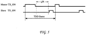
- FIG. 5 illustrates the TX_ON signal for a system with Low Power Idle (LPI) capability.
- LPI Low Power Idle
- a periodic minimum transmission of data or idle signal is considered to ensure that the receiver DSP status is maintained. It is a feature of the present invention that LPI can be considered and combined with symmetric, asymmetric or adaptive burst time allocations.
- the clock at the MII interface or CLK1 may be adjusted to allow for this rate change if the MAC device allows for the intermediate clock speeds. It is also possible to select a fixed higher rate clock at the MII interface and use flow control to allow for variable and/or adjustable throughput at the downlink and uplink. IEEE standard PAUSE commands can also be used to provide flow control in this case.
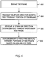
- the process begins at step 602 where a TDD frame is defined.
- the TDD frame can be considered as a constant while uplink and downlink transmission periods vary within the TDD frame.
- the TDD frame can describe uplink and downlink transmission periods to suit a given traffic profile on a network link.
- the uplink and downlink transmission periods can be defined with equal time periods or unequal time periods.
- the transmitter in the uplink direction can be given transmission control based on a TX_ON signal generated by a controller in a first physical layer device during a first transmit portion of the TDD frame.
- This TX_ON signal can be generated by the controller in accordance with the TDD frame structure that was defined.
- transmission control would effectively be given to a second physical layer device at the other end of the link, where a corresponding TX_ON signal is generated to indicate that transmission in the down link direction can proceed.
- the first physical layer device would then receive data during the second transmit portion of the TDD frame.
- the time periods corresponding to transmission in the uplink and downlink directions can be varied dynamically in the context of the TDD frame.
- the length of the first and second transmit portions can be adjusted based on the availability of data. For example, an indication that a given direction of transmission is having a negative impact on bandwidth and latency, can lead to an adjustment in the defined TDD structure as to the uplink and downlink transmission periods.
- the particular mechanism used to initiate the adjustments can vary based on the granularity of desired in the adjustment mechanism.
- the adjustment can be made to respond to a particular FIFO level at a moment of time.
- the adjustment can be made to respond to a statistical measure of bandwidth and/or latency over a particular monitored period of time.
- the principles of the present invention can be applied to a single-pair or a multi-pair cable network. Moreover, the principles of the present invention can be used with twisted-pair cables, coaxial cables or fiber optic cables. Significantly, the principles of the present invention can be combined and used with various modulation techniques. Additionally, the principles of the present invention can be designed with predefined uplink and downlink throughputs or can be made programmable or even adaptive.
Landscapes
- Engineering & Computer Science (AREA)
- Signal Processing (AREA)
- Computer Networks & Wireless Communication (AREA)
- Multimedia (AREA)
- Small-Scale Networks (AREA)
- Bidirectional Digital Transmission (AREA)
Claims (9)
- Verfahren bei einer ersten Ethernet Bitübertragungsschicht-Vorrichtung, die mit einer zweiten Ethernet Bitübertragungsschicht-Vorrichtung über eine Einzelpaar-Netzwerkverbindung verbunden ist, wobei das Verfahren umfasst:Empfangen von Sendesteuerung während eines ersten Zeitabschnitts, wobei die Sendesteuerung der ersten Ethernet Bitübertragungsschicht-Vorrichtung die Verwendung der Einzelpaar-Netzwerkverbindung zum Senden an die zweite Ethernet Bitübertragungsschicht-Vorrichtung vorsieht, wobei während des ersten Zeitabschnitts die zweite Ethernet Bitübertragungsschicht-Vorrichtung daran gehindert wird, über die Einzelpaar-Netzwerkverbindung zu senden;Empfangen von Daten, die von der zweiten Ethernet Bitübertragungsschicht-Vorrichtung während eines zweiten Zeitabschnitts, der auf den ersten Zeitabschnitt folgt, gesendet werden, wobei während des zweiten Zeitabschnitts die Sendesteuerung an die zweite Ethernet Bitübertragungsschicht-Vorrichtung abgetreten wird und die erste Ethernet Bitübertragungsschicht-Vorrichtung daran gehindert wird, über die Einzelpaar-Netzwerkverbindung zu senden, wobei der erste Zeitabschnitt und der zweite Zeitabschnitt zusammen mit zwei Abstandszeiträumen zwischen dem Senden durch die erste und die zweite Ethernet Bitübertragungsschicht-Vorrichtung einen sich wiederholenden Zeitduplexrahmen bilden;Verkürzen der Länge des ersten Zeitabschnitts, wenn die erste Ethernet Bitübertragungsschicht-Vorrichtung keine Daten zum Senden hat; undAufrechterhalten eines Empfänger-DSP-Status durch periodisches minimales Senden von Daten oder Ruhesignalen.
- Verfahren nach Anspruch 1, wobei der erste Zeitabschnitt und der zweite Zeitabschnitt durch einen Zwischenburst-Abstand getrennt sind.
- Verfahren nach Anspruch 1, wobei der erste Zeitabschnitt und der zweite Zeitabschnitt unterschiedliche Länge haben.
- Verfahren nach Anspruch 1, das des Weiteren das Eintreten, durch die erste Bitübertragungsschicht-Vorrichtung, in einen Niedrigleistungs-Leerlaufmodus während des ersten Zeitabschnitts umfasst, wenn die erste Ethernet Bitübertragungsschicht-Vorrichtung keine Daten zum Senden hat.
- Ethernet Bitübertragungsschicht-Vorrichtung zur Verwendung mit einem Einzelpaarkabel, die aufweist:einen ersten Sender, der mit einem Einzelpaarkabel verbunden ist, wobei der erste Sender auf ein Sendesteuersignal anspricht, das einen ersten zugeteilten Zeitabschnitt bestimmt, in dem Daten von dem ersten Sender über das Einzelpaarkabel gesendet werden können, und in dem Daten von einem zweiten Sender in einer zweiten Ethernet Bitübertragungsschicht-Vorrichtung nicht über das Einzelpaarkabel gesendet werden können; undeinen Controller, der das Sendesteuersignal erzeugt, wobei der Controller dazu ausgelegt ist, mit der zweiten Ethernet Bitübertragungsschicht-Vorrichtung zusammenzuarbeiten, um einen zweiten zugeteilten Zeitabschnitt nach dem ersten zugeteilten Zeitabschnitt zu definieren, in dem der erste Sender keine Daten über das Einzelpaarkabel senden kann und der zweite Sender Daten über das Einzelpaarkabel senden kann;wobei der Controller die Länge des ersten zugeteilten Zeitabschnitts verkürzt, wenn die erste Ethernet Bitübertragungsschicht-Vorrichtung keine Daten zum Senden hat;wobei die Ethernet Bitübertragungsschicht-Vorrichtung dazu konfiguriert ist, einen Empfänger-DSP-Status durch periodisches minimales Senden von Daten oder Leerlaufsignalen aufrecht zu erhalten.
- Vorrichtung nach Anspruch 5, wobei der erste zugeteilte Zeitabschnitt und der zweite zugeteilte Zeitabschnitt durch einen Zwischenburstabstand getrennt sind.
- Vorrichtung nach Anspruch 5, wobei der erste zugeteilte Zeitabschnitt und der zweite zugeteilte Zeitabschnitt unterschiedlich lang sind.
- Vorrichtung nach Anspruch 5, wobei die erste Bitübertragungsschicht-Vorrichtung während des ersten zugeteilten Zeitabschnitts in einen Niedrigleistungs-Leerlaufmodus eintritt, wenn die erste Ethernet Bitübertragungsschicht-Vorrichtung keine Daten zum Senden hat.
- Vorrichtung nach Anspruch 5, die des Weiteren einen FIFO-Puffer an einer Medienzugriffs-Steuerschichtschnittstelle hat, wobei ein Takt an einer ersten Seite des FIFO-Puffers schneller als an einer zweiten Seite des FIFO-Puffers ist.
Applications Claiming Priority (2)
| Application Number | Priority Date | Filing Date | Title |
|---|---|---|---|
| US201161531184P | 2011-09-06 | 2011-09-06 | |
| US13/300,996 US9001714B2 (en) | 2011-09-06 | 2011-11-21 | Ethernet physical layer device using time division duplex |
Publications (3)
| Publication Number | Publication Date |
|---|---|
| EP2568652A1 EP2568652A1 (de) | 2013-03-13 |
| EP2568652B1 true EP2568652B1 (de) | 2018-12-19 |
| EP2568652B8 EP2568652B8 (de) | 2019-02-27 |
Family
ID=46796198
Family Applications (1)
| Application Number | Title | Priority Date | Filing Date |
|---|---|---|---|
| EP12005500.9A Active EP2568652B8 (de) | 2011-09-06 | 2012-07-27 | Ethernet-PHY mit Verwendung von Zeitstaffelduplex |
Country Status (5)
| Country | Link |
|---|---|
| US (2) | US9001714B2 (de) |
| EP (1) | EP2568652B8 (de) |
| KR (1) | KR101375823B1 (de) |
| CN (1) | CN102983930B (de) |
| TW (1) | TWI486003B (de) |
Families Citing this family (8)
| Publication number | Priority date | Publication date | Assignee | Title |
|---|---|---|---|---|
| EP2847938A4 (de) * | 2012-05-09 | 2016-01-13 | Qualcomm Inc | Voll-duplex ethernet-kommunikationen über koaxialkabelverknüpfungen mit zeitduplexing |
| ES2913444T3 (es) * | 2013-03-21 | 2022-06-02 | Huawei Tech Co Ltd | Aparato de transmisión, método de transmisión de datos y soporte de grabación legible por ordenador no transitorio |
| US10313091B2 (en) * | 2015-11-06 | 2019-06-04 | Avago Technologies International Sales Pte. Limited | Robust electromagnetic compatibility performance for in-vehicle Ethernet PHYs utilizing time division duplexing |
| US11038607B2 (en) * | 2018-09-11 | 2021-06-15 | Synaptics Incorporated | Method and system for bi-directional communication |
| US12095709B2 (en) * | 2020-03-16 | 2024-09-17 | Sony Semiconductor Solutions Corporation | Communication device, communication system and communication method |
| EP4057575B1 (de) * | 2021-03-10 | 2026-01-07 | Infineon Technologies Americas Corp. | Konfigurierbare übertragungsraten über eine zweiweg-ethernet-verbindung |
| US11784779B2 (en) | 2021-12-09 | 2023-10-10 | Marvell Asia Pte Ltd | Automotive asymmetric ethernet using a frequency-division duplex scheme with a low-rate echo cancelation |
| CN116633707A (zh) * | 2022-02-11 | 2023-08-22 | 华为技术有限公司 | 一种通信方法及通信装置 |
Family Cites Families (11)
| Publication number | Priority date | Publication date | Assignee | Title |
|---|---|---|---|---|
| JPS5875345A (ja) | 1981-10-30 | 1983-05-07 | Fuji Xerox Co Ltd | デイジタル信号伝送方式 |
| US6178161B1 (en) | 1997-10-31 | 2001-01-23 | Nortel Networks Corporation | Communications methods and apparatus |
| US6804211B1 (en) * | 1999-08-03 | 2004-10-12 | Wi-Lan Inc. | Frame structure for an adaptive modulation wireless communication system |
| US7245628B2 (en) | 2001-07-10 | 2007-07-17 | Haixing Shi | Allocation of upstream bandwidth in an ethernet passive optical network |
| KR100478760B1 (ko) | 2002-04-26 | 2005-03-24 | (주)넷비젼텔레콤 | 2가닥 선로를 통한 이더넷 프레임 전달 장치 |
| US7548549B2 (en) | 2004-11-04 | 2009-06-16 | Jacobi Systems Corporation | Method and apparatus for transmission of digital signals over a coaxial cable |
| GB2440986A (en) * | 2006-08-18 | 2008-02-20 | Fujitsu Ltd | Wireless multi-hop communication system |
| CN101420280A (zh) * | 2007-10-25 | 2009-04-29 | 西门子公司 | 一种低功率通信网络中的通信方法、系统及网络节点 |
| US8064373B2 (en) | 2007-12-17 | 2011-11-22 | Broadcom Corporation | Method and system for simplex or duplex transmission mode of an ethernet link in an energy efficient network |
| US8638711B2 (en) | 2009-08-11 | 2014-01-28 | Qualcomm Incorporated | Systems and methods of maintaining core network status during serving radio network subsystem relocation |
| CN102111860B (zh) * | 2009-12-25 | 2013-08-14 | 电信科学技术研究院 | 一种信道的功率控制方法及设备 |
-
2011
- 2011-11-21 US US13/300,996 patent/US9001714B2/en active Active
-
2012
- 2012-07-27 EP EP12005500.9A patent/EP2568652B8/de active Active
- 2012-08-14 KR KR1020120088752A patent/KR101375823B1/ko active Active
- 2012-08-27 TW TW101130968A patent/TWI486003B/zh not_active IP Right Cessation
- 2012-09-06 CN CN201210328741.3A patent/CN102983930B/zh not_active Expired - Fee Related
-
2015
- 2015-02-04 US US14/613,491 patent/US9258105B2/en active Active
Non-Patent Citations (1)
| Title |
|---|
| None * |
Also Published As
| Publication number | Publication date |
|---|---|
| US20130058265A1 (en) | 2013-03-07 |
| TW201312958A (zh) | 2013-03-16 |
| EP2568652B8 (de) | 2019-02-27 |
| CN102983930B (zh) | 2016-09-07 |
| KR20130026981A (ko) | 2013-03-14 |
| CN102983930A (zh) | 2013-03-20 |
| KR101375823B1 (ko) | 2014-03-20 |
| EP2568652A1 (de) | 2013-03-13 |
| US9258105B2 (en) | 2016-02-09 |
| US20150146590A1 (en) | 2015-05-28 |
| HK1178339A1 (zh) | 2013-09-06 |
| US9001714B2 (en) | 2015-04-07 |
| TWI486003B (zh) | 2015-05-21 |
Similar Documents
| Publication | Publication Date | Title |
|---|---|---|
| US9258105B2 (en) | Ethernet physical layer device using time division duplex | |
| EP3309983B1 (de) | Übertragungsschema für kommunikationssysteme | |
| EP1997249B1 (de) | Verfahren und vorrichtung zur dynamischen änderung der präambellänge einer burst-kommunikation | |
| US11296858B2 (en) | Communications device and method of communications | |
| US11038607B2 (en) | Method and system for bi-directional communication | |
| US9525639B2 (en) | 2.5 GBPS/5GBPS ethernet communications over a full duplex communication channel | |
| US9722765B2 (en) | Method and apparatus for managing processing in TDD frames to enable power dissipation reduction | |
| CN105828112B (zh) | 基于竞争的网络中的带宽获取 | |
| US20150117465A1 (en) | Communication control apparatus and communication control method | |
| US20150229432A1 (en) | Full-duplex ethernet communications over coaxial links using time-division duplexing | |
| US7099302B2 (en) | Data transmission network | |
| US8644267B2 (en) | Wireless communication system and method of calling terminal | |
| CN111212308B (zh) | 一种无线网络自适应调节的方法 | |
| US10420140B2 (en) | Multi-destination burst protocol | |
| CN101990141A (zh) | 一种实现宽带接入的方法和装置 | |
| HK1178339B (en) | Ethernet physical layer device using time division duplex | |
| WO2009127734A1 (en) | Network apparatus and controlling method therefore | |
| TWI422258B (zh) | 無線通信系統以及無線通信系統中的無線電資源的有效利用方法 | |
| Abedin et al. | Scheduled bus protocol for mixed voice and data local communications | |
| HK1178343A1 (zh) | 双层网络中的调度 | |
| HK1178343B (zh) | 双层网络中的调度 | |
| JPS61203747A (ja) | 2線式双方向バス伝送方式 |
Legal Events
| Date | Code | Title | Description |
|---|---|---|---|
| PUAI | Public reference made under article 153(3) epc to a published international application that has entered the european phase |
Free format text: ORIGINAL CODE: 0009012 |
|
| 17P | Request for examination filed |
Effective date: 20120727 |
|
| AK | Designated contracting states |
Kind code of ref document: A1 Designated state(s): AL AT BE BG CH CY CZ DE DK EE ES FI FR GB GR HR HU IE IS IT LI LT LU LV MC MK MT NL NO PL PT RO RS SE SI SK SM TR |
|
| AX | Request for extension of the european patent |
Extension state: BA ME |
|
| RBV | Designated contracting states (corrected) |
Designated state(s): AL AT BE BG CH CY CZ DE DK EE ES FI FR GB GR HR HU IE IS IT LI LT LU LV MC MK MT NL NO PL PT RO RS SE SI SK SM TR |
|
| STAA | Information on the status of an ep patent application or granted ep patent |
Free format text: STATUS: EXAMINATION IS IN PROGRESS |
|
| RAP1 | Party data changed (applicant data changed or rights of an application transferred) |
Owner name: AVAGO TECHNOLOGIES GENERAL IP (SINGAPORE) PTE. LTD |
|
| GRAJ | Information related to disapproval of communication of intention to grant by the applicant or resumption of examination proceedings by the epo deleted |
Free format text: ORIGINAL CODE: EPIDOSDIGR1 |
|
| STAA | Information on the status of an ep patent application or granted ep patent |
Free format text: STATUS: GRANT OF PATENT IS INTENDED |
|
| GRAP | Despatch of communication of intention to grant a patent |
Free format text: ORIGINAL CODE: EPIDOSNIGR1 |
|
| RIC1 | Information provided on ipc code assigned before grant |
Ipc: H04L 5/14 20060101AFI20180627BHEP Ipc: H04L 12/403 20060101ALI20180627BHEP |
|
| INTG | Intention to grant announced |
Effective date: 20180709 |
|
| RIN1 | Information on inventor provided before grant (corrected) |
Inventor name: POWELL, SCOTT Inventor name: TAZEBAY, MEHMET Inventor name: CHINI, AHMAD |
|
| GRAS | Grant fee paid |
Free format text: ORIGINAL CODE: EPIDOSNIGR3 |
|
| GRAA | (expected) grant |
Free format text: ORIGINAL CODE: 0009210 |
|
| STAA | Information on the status of an ep patent application or granted ep patent |
Free format text: STATUS: THE PATENT HAS BEEN GRANTED |
|
| AK | Designated contracting states |
Kind code of ref document: B1 Designated state(s): AL AT BE BG CH CY CZ DE DK EE ES FI FR GB GR HR HU IE IS IT LI LT LU LV MC MK MT NL NO PL PT RO RS SE SI SK SM TR |
|
| REG | Reference to a national code |
Ref country code: GB Ref legal event code: FG4D |
|
| RAP2 | Party data changed (patent owner data changed or rights of a patent transferred) |
Owner name: AVAGO TECHNOLOGIES INTERNATIONAL SALES PTE. LIMITE |
|
| REG | Reference to a national code |
Ref country code: CH Ref legal event code: EP |
|
| REG | Reference to a national code |
Ref country code: IE Ref legal event code: FG4D |
|
| REG | Reference to a national code |
Ref country code: DE Ref legal event code: R096 Ref document number: 602012054756 Country of ref document: DE |
|
| REG | Reference to a national code |
Ref country code: AT Ref legal event code: REF Ref document number: 1079854 Country of ref document: AT Kind code of ref document: T Effective date: 20190115 |
|
| REG | Reference to a national code |
Ref country code: CH Ref legal event code: PK Free format text: BERICHTIGUNG B8 |
|
| REG | Reference to a national code |
Ref country code: NL Ref legal event code: FP |
|
| PG25 | Lapsed in a contracting state [announced via postgrant information from national office to epo] |
Ref country code: NO Free format text: LAPSE BECAUSE OF FAILURE TO SUBMIT A TRANSLATION OF THE DESCRIPTION OR TO PAY THE FEE WITHIN THE PRESCRIBED TIME-LIMIT Effective date: 20190319 Ref country code: LV Free format text: LAPSE BECAUSE OF FAILURE TO SUBMIT A TRANSLATION OF THE DESCRIPTION OR TO PAY THE FEE WITHIN THE PRESCRIBED TIME-LIMIT Effective date: 20181219 Ref country code: LT Free format text: LAPSE BECAUSE OF FAILURE TO SUBMIT A TRANSLATION OF THE DESCRIPTION OR TO PAY THE FEE WITHIN THE PRESCRIBED TIME-LIMIT Effective date: 20181219 Ref country code: FI Free format text: LAPSE BECAUSE OF FAILURE TO SUBMIT A TRANSLATION OF THE DESCRIPTION OR TO PAY THE FEE WITHIN THE PRESCRIBED TIME-LIMIT Effective date: 20181219 Ref country code: BG Free format text: LAPSE BECAUSE OF FAILURE TO SUBMIT A TRANSLATION OF THE DESCRIPTION OR TO PAY THE FEE WITHIN THE PRESCRIBED TIME-LIMIT Effective date: 20190319 Ref country code: HR Free format text: LAPSE BECAUSE OF FAILURE TO SUBMIT A TRANSLATION OF THE DESCRIPTION OR TO PAY THE FEE WITHIN THE PRESCRIBED TIME-LIMIT Effective date: 20181219 |
|
| REG | Reference to a national code |
Ref country code: LT Ref legal event code: MG4D |
|
| REG | Reference to a national code |
Ref country code: AT Ref legal event code: MK05 Ref document number: 1079854 Country of ref document: AT Kind code of ref document: T Effective date: 20181219 |
|
| PG25 | Lapsed in a contracting state [announced via postgrant information from national office to epo] |
Ref country code: GR Free format text: LAPSE BECAUSE OF FAILURE TO SUBMIT A TRANSLATION OF THE DESCRIPTION OR TO PAY THE FEE WITHIN THE PRESCRIBED TIME-LIMIT Effective date: 20190320 Ref country code: SE Free format text: LAPSE BECAUSE OF FAILURE TO SUBMIT A TRANSLATION OF THE DESCRIPTION OR TO PAY THE FEE WITHIN THE PRESCRIBED TIME-LIMIT Effective date: 20181219 Ref country code: AL Free format text: LAPSE BECAUSE OF FAILURE TO SUBMIT A TRANSLATION OF THE DESCRIPTION OR TO PAY THE FEE WITHIN THE PRESCRIBED TIME-LIMIT Effective date: 20181219 Ref country code: RS Free format text: LAPSE BECAUSE OF FAILURE TO SUBMIT A TRANSLATION OF THE DESCRIPTION OR TO PAY THE FEE WITHIN THE PRESCRIBED TIME-LIMIT Effective date: 20181219 |
|
| PG25 | Lapsed in a contracting state [announced via postgrant information from national office to epo] |
Ref country code: ES Free format text: LAPSE BECAUSE OF FAILURE TO SUBMIT A TRANSLATION OF THE DESCRIPTION OR TO PAY THE FEE WITHIN THE PRESCRIBED TIME-LIMIT Effective date: 20181219 Ref country code: PL Free format text: LAPSE BECAUSE OF FAILURE TO SUBMIT A TRANSLATION OF THE DESCRIPTION OR TO PAY THE FEE WITHIN THE PRESCRIBED TIME-LIMIT Effective date: 20181219 Ref country code: PT Free format text: LAPSE BECAUSE OF FAILURE TO SUBMIT A TRANSLATION OF THE DESCRIPTION OR TO PAY THE FEE WITHIN THE PRESCRIBED TIME-LIMIT Effective date: 20190419 Ref country code: CZ Free format text: LAPSE BECAUSE OF FAILURE TO SUBMIT A TRANSLATION OF THE DESCRIPTION OR TO PAY THE FEE WITHIN THE PRESCRIBED TIME-LIMIT Effective date: 20181219 Ref country code: IT Free format text: LAPSE BECAUSE OF FAILURE TO SUBMIT A TRANSLATION OF THE DESCRIPTION OR TO PAY THE FEE WITHIN THE PRESCRIBED TIME-LIMIT Effective date: 20181219 |
|
| PG25 | Lapsed in a contracting state [announced via postgrant information from national office to epo] |
Ref country code: RO Free format text: LAPSE BECAUSE OF FAILURE TO SUBMIT A TRANSLATION OF THE DESCRIPTION OR TO PAY THE FEE WITHIN THE PRESCRIBED TIME-LIMIT Effective date: 20181219 Ref country code: IS Free format text: LAPSE BECAUSE OF FAILURE TO SUBMIT A TRANSLATION OF THE DESCRIPTION OR TO PAY THE FEE WITHIN THE PRESCRIBED TIME-LIMIT Effective date: 20190419 Ref country code: EE Free format text: LAPSE BECAUSE OF FAILURE TO SUBMIT A TRANSLATION OF THE DESCRIPTION OR TO PAY THE FEE WITHIN THE PRESCRIBED TIME-LIMIT Effective date: 20181219 Ref country code: SM Free format text: LAPSE BECAUSE OF FAILURE TO SUBMIT A TRANSLATION OF THE DESCRIPTION OR TO PAY THE FEE WITHIN THE PRESCRIBED TIME-LIMIT Effective date: 20181219 Ref country code: SK Free format text: LAPSE BECAUSE OF FAILURE TO SUBMIT A TRANSLATION OF THE DESCRIPTION OR TO PAY THE FEE WITHIN THE PRESCRIBED TIME-LIMIT Effective date: 20181219 |
|
| REG | Reference to a national code |
Ref country code: DE Ref legal event code: R097 Ref document number: 602012054756 Country of ref document: DE |
|
| PLBE | No opposition filed within time limit |
Free format text: ORIGINAL CODE: 0009261 |
|
| STAA | Information on the status of an ep patent application or granted ep patent |
Free format text: STATUS: NO OPPOSITION FILED WITHIN TIME LIMIT |
|
| PG25 | Lapsed in a contracting state [announced via postgrant information from national office to epo] |
Ref country code: AT Free format text: LAPSE BECAUSE OF FAILURE TO SUBMIT A TRANSLATION OF THE DESCRIPTION OR TO PAY THE FEE WITHIN THE PRESCRIBED TIME-LIMIT Effective date: 20181219 Ref country code: DK Free format text: LAPSE BECAUSE OF FAILURE TO SUBMIT A TRANSLATION OF THE DESCRIPTION OR TO PAY THE FEE WITHIN THE PRESCRIBED TIME-LIMIT Effective date: 20181219 |
|
| 26N | No opposition filed |
Effective date: 20190920 |
|
| PG25 | Lapsed in a contracting state [announced via postgrant information from national office to epo] |
Ref country code: MC Free format text: LAPSE BECAUSE OF FAILURE TO SUBMIT A TRANSLATION OF THE DESCRIPTION OR TO PAY THE FEE WITHIN THE PRESCRIBED TIME-LIMIT Effective date: 20181219 Ref country code: SI Free format text: LAPSE BECAUSE OF FAILURE TO SUBMIT A TRANSLATION OF THE DESCRIPTION OR TO PAY THE FEE WITHIN THE PRESCRIBED TIME-LIMIT Effective date: 20181219 |
|
| REG | Reference to a national code |
Ref country code: CH Ref legal event code: PL |
|
| GBPC | Gb: european patent ceased through non-payment of renewal fee |
Effective date: 20190727 |
|
| PG25 | Lapsed in a contracting state [announced via postgrant information from national office to epo] |
Ref country code: TR Free format text: LAPSE BECAUSE OF FAILURE TO SUBMIT A TRANSLATION OF THE DESCRIPTION OR TO PAY THE FEE WITHIN THE PRESCRIBED TIME-LIMIT Effective date: 20181219 |
|
| REG | Reference to a national code |
Ref country code: BE Ref legal event code: MM Effective date: 20190731 |
|
| PG25 | Lapsed in a contracting state [announced via postgrant information from national office to epo] |
Ref country code: GB Free format text: LAPSE BECAUSE OF NON-PAYMENT OF DUE FEES Effective date: 20190727 |
|
| PG25 | Lapsed in a contracting state [announced via postgrant information from national office to epo] |
Ref country code: LU Free format text: LAPSE BECAUSE OF NON-PAYMENT OF DUE FEES Effective date: 20190727 Ref country code: LI Free format text: LAPSE BECAUSE OF NON-PAYMENT OF DUE FEES Effective date: 20190731 Ref country code: CH Free format text: LAPSE BECAUSE OF NON-PAYMENT OF DUE FEES Effective date: 20190731 Ref country code: BE Free format text: LAPSE BECAUSE OF NON-PAYMENT OF DUE FEES Effective date: 20190731 |
|
| PG25 | Lapsed in a contracting state [announced via postgrant information from national office to epo] |
Ref country code: FR Free format text: LAPSE BECAUSE OF NON-PAYMENT OF DUE FEES Effective date: 20190731 |
|
| PG25 | Lapsed in a contracting state [announced via postgrant information from national office to epo] |
Ref country code: IE Free format text: LAPSE BECAUSE OF NON-PAYMENT OF DUE FEES Effective date: 20190727 |
|
| PG25 | Lapsed in a contracting state [announced via postgrant information from national office to epo] |
Ref country code: CY Free format text: LAPSE BECAUSE OF FAILURE TO SUBMIT A TRANSLATION OF THE DESCRIPTION OR TO PAY THE FEE WITHIN THE PRESCRIBED TIME-LIMIT Effective date: 20181219 |
|
| PG25 | Lapsed in a contracting state [announced via postgrant information from national office to epo] |
Ref country code: HU Free format text: LAPSE BECAUSE OF FAILURE TO SUBMIT A TRANSLATION OF THE DESCRIPTION OR TO PAY THE FEE WITHIN THE PRESCRIBED TIME-LIMIT; INVALID AB INITIO Effective date: 20120727 Ref country code: MT Free format text: LAPSE BECAUSE OF FAILURE TO SUBMIT A TRANSLATION OF THE DESCRIPTION OR TO PAY THE FEE WITHIN THE PRESCRIBED TIME-LIMIT Effective date: 20181219 |
|
| PG25 | Lapsed in a contracting state [announced via postgrant information from national office to epo] |
Ref country code: MK Free format text: LAPSE BECAUSE OF FAILURE TO SUBMIT A TRANSLATION OF THE DESCRIPTION OR TO PAY THE FEE WITHIN THE PRESCRIBED TIME-LIMIT Effective date: 20181219 |
|
| PGFP | Annual fee paid to national office [announced via postgrant information from national office to epo] |
Ref country code: NL Payment date: 20250620 Year of fee payment: 14 |
|
| PGFP | Annual fee paid to national office [announced via postgrant information from national office to epo] |
Ref country code: DE Payment date: 20250710 Year of fee payment: 14 |