EP2568547A1 - Monitor diode-free laser driver - Google Patents
Monitor diode-free laser driver Download PDFInfo
- Publication number
- EP2568547A1 EP2568547A1 EP11180282A EP11180282A EP2568547A1 EP 2568547 A1 EP2568547 A1 EP 2568547A1 EP 11180282 A EP11180282 A EP 11180282A EP 11180282 A EP11180282 A EP 11180282A EP 2568547 A1 EP2568547 A1 EP 2568547A1
- Authority
- EP
- European Patent Office
- Prior art keywords
- laser
- laser diode
- voltage
- pulse
- diode
- Prior art date
- Legal status (The legal status is an assumption and is not a legal conclusion. Google has not performed a legal analysis and makes no representation as to the accuracy of the status listed.)
- Granted
Links
- 230000001939 inductive effect Effects 0.000 claims abstract description 36
- 238000000034 method Methods 0.000 claims abstract description 20
- 238000012544 monitoring process Methods 0.000 claims description 17
- 230000003068 static effect Effects 0.000 claims description 9
- 238000007493 shaping process Methods 0.000 claims description 8
- 238000001514 detection method Methods 0.000 claims description 6
- 230000003247 decreasing effect Effects 0.000 claims 1
- 238000010586 diagram Methods 0.000 description 8
- 238000004891 communication Methods 0.000 description 7
- 238000013461 design Methods 0.000 description 4
- 238000005516 engineering process Methods 0.000 description 4
- 230000003287 optical effect Effects 0.000 description 4
- 230000002829 reductive effect Effects 0.000 description 4
- 238000004519 manufacturing process Methods 0.000 description 3
- 230000005855 radiation Effects 0.000 description 3
- 230000003679 aging effect Effects 0.000 description 2
- 239000004020 conductor Substances 0.000 description 2
- 238000010276 construction Methods 0.000 description 2
- 230000001419 dependent effect Effects 0.000 description 2
- 238000011156 evaluation Methods 0.000 description 2
- 239000010408 film Substances 0.000 description 2
- 238000005259 measurement Methods 0.000 description 2
- 239000004065 semiconductor Substances 0.000 description 2
- 238000000926 separation method Methods 0.000 description 2
- 230000002269 spontaneous effect Effects 0.000 description 2
- 239000010409 thin film Substances 0.000 description 2
- 230000001960 triggered effect Effects 0.000 description 2
- 238000013459 approach Methods 0.000 description 1
- 239000003990 capacitor Substances 0.000 description 1
- 230000015556 catabolic process Effects 0.000 description 1
- 238000006243 chemical reaction Methods 0.000 description 1
- 210000004087 cornea Anatomy 0.000 description 1
- 238000006731 degradation reaction Methods 0.000 description 1
- 238000011161 development Methods 0.000 description 1
- 230000018109 developmental process Effects 0.000 description 1
- 238000007599 discharging Methods 0.000 description 1
- 230000000694 effects Effects 0.000 description 1
- 230000005670 electromagnetic radiation Effects 0.000 description 1
- 231100000040 eye damage Toxicity 0.000 description 1
- 210000000744 eyelid Anatomy 0.000 description 1
- 230000005669 field effect Effects 0.000 description 1
- 238000011990 functional testing Methods 0.000 description 1
- 238000009499 grossing Methods 0.000 description 1
- 230000010354 integration Effects 0.000 description 1
- 230000000670 limiting effect Effects 0.000 description 1
- 230000003071 parasitic effect Effects 0.000 description 1
- 230000036961 partial effect Effects 0.000 description 1
- 230000002093 peripheral effect Effects 0.000 description 1
- 230000008092 positive effect Effects 0.000 description 1
- 230000001681 protective effect Effects 0.000 description 1
- 230000011514 reflex Effects 0.000 description 1
- 230000001105 regulatory effect Effects 0.000 description 1
- 210000001525 retina Anatomy 0.000 description 1
- 238000009781 safety test method Methods 0.000 description 1
- 238000004088 simulation Methods 0.000 description 1
- 238000012360 testing method Methods 0.000 description 1
- 231100000041 toxicology testing Toxicity 0.000 description 1
- 238000011144 upstream manufacturing Methods 0.000 description 1
Images


Classifications
-
- G—PHYSICS
- G01—MEASURING; TESTING
- G01S—RADIO DIRECTION-FINDING; RADIO NAVIGATION; DETERMINING DISTANCE OR VELOCITY BY USE OF RADIO WAVES; LOCATING OR PRESENCE-DETECTING BY USE OF THE REFLECTION OR RERADIATION OF RADIO WAVES; ANALOGOUS ARRANGEMENTS USING OTHER WAVES
- G01S17/00—Systems using the reflection or reradiation of electromagnetic waves other than radio waves, e.g. lidar systems
- G01S17/02—Systems using the reflection of electromagnetic waves other than radio waves
- G01S17/06—Systems determining position data of a target
- G01S17/08—Systems determining position data of a target for measuring distance only
- G01S17/10—Systems determining position data of a target for measuring distance only using transmission of interrupted, pulse-modulated waves
-
- H—ELECTRICITY
- H01—ELECTRIC ELEMENTS
- H01S—DEVICES USING THE PROCESS OF LIGHT AMPLIFICATION BY STIMULATED EMISSION OF RADIATION [LASER] TO AMPLIFY OR GENERATE LIGHT; DEVICES USING STIMULATED EMISSION OF ELECTROMAGNETIC RADIATION IN WAVE RANGES OTHER THAN OPTICAL
- H01S5/00—Semiconductor lasers
- H01S5/04—Processes or apparatus for excitation, e.g. pumping, e.g. by electron beams
- H01S5/042—Electrical excitation ; Circuits therefor
- H01S5/0428—Electrical excitation ; Circuits therefor for applying pulses to the laser
-
- G—PHYSICS
- G01—MEASURING; TESTING
- G01B—MEASURING LENGTH, THICKNESS OR SIMILAR LINEAR DIMENSIONS; MEASURING ANGLES; MEASURING AREAS; MEASURING IRREGULARITIES OF SURFACES OR CONTOURS
- G01B11/00—Measuring arrangements characterised by the use of optical techniques
- G01B11/14—Measuring arrangements characterised by the use of optical techniques for measuring distance or clearance between spaced objects or spaced apertures
-
- H—ELECTRICITY
- H01—ELECTRIC ELEMENTS
- H01S—DEVICES USING THE PROCESS OF LIGHT AMPLIFICATION BY STIMULATED EMISSION OF RADIATION [LASER] TO AMPLIFY OR GENERATE LIGHT; DEVICES USING STIMULATED EMISSION OF ELECTROMAGNETIC RADIATION IN WAVE RANGES OTHER THAN OPTICAL
- H01S5/00—Semiconductor lasers
- H01S5/0014—Measuring characteristics or properties thereof
-
- H—ELECTRICITY
- H01—ELECTRIC ELEMENTS
- H01S—DEVICES USING THE PROCESS OF LIGHT AMPLIFICATION BY STIMULATED EMISSION OF RADIATION [LASER] TO AMPLIFY OR GENERATE LIGHT; DEVICES USING STIMULATED EMISSION OF ELECTROMAGNETIC RADIATION IN WAVE RANGES OTHER THAN OPTICAL
- H01S5/00—Semiconductor lasers
- H01S5/06—Arrangements for controlling the laser output parameters, e.g. by operating on the active medium
- H01S5/068—Stabilisation of laser output parameters
- H01S5/06825—Protecting the laser, e.g. during switch-on/off, detection of malfunctioning or degradation
-
- H—ELECTRICITY
- H03—ELECTRONIC CIRCUITRY
- H03K—PULSE TECHNIQUE
- H03K3/00—Circuits for generating electric pulses; Monostable, bistable or multistable circuits
- H03K3/02—Generators characterised by the type of circuit or by the means used for producing pulses
- H03K3/53—Generators characterised by the type of circuit or by the means used for producing pulses by the use of an energy-accumulating element discharged through the load by a switching device controlled by an external signal and not incorporating positive feedback
- H03K3/57—Generators characterised by the type of circuit or by the means used for producing pulses by the use of an energy-accumulating element discharged through the load by a switching device controlled by an external signal and not incorporating positive feedback the switching device being a semiconductor device
-
- G—PHYSICS
- G01—MEASURING; TESTING
- G01S—RADIO DIRECTION-FINDING; RADIO NAVIGATION; DETERMINING DISTANCE OR VELOCITY BY USE OF RADIO WAVES; LOCATING OR PRESENCE-DETECTING BY USE OF THE REFLECTION OR RERADIATION OF RADIO WAVES; ANALOGOUS ARRANGEMENTS USING OTHER WAVES
- G01S7/00—Details of systems according to groups G01S13/00, G01S15/00, G01S17/00
- G01S7/48—Details of systems according to groups G01S13/00, G01S15/00, G01S17/00 of systems according to group G01S17/00
- G01S7/483—Details of pulse systems
- G01S7/484—Transmitters
Definitions
- the invention relates to a safe laser driver according to the preamble of claim 1 and a driving method for a semiconductor laser, in particular a method for generating a laser pulse according to the preamble of claim 10.
- the general guidelines for laser safety require that a laser light source only be operated in such a way that it poses no danger. Depending on the emitted wavelength, limit values of the thermal power density or the energy density must be observed.
- Eye safety is of primary importance to laser devices, as the eye reacts most sensitively to electromagnetic radiation due to its function, and damage to the retina or cornea can occur through direct, indirect or scattered laser beams. This is particularly true since studies have shown that even with visible light from the eyelid closure reflex to the protection of the eye can not be expected in the rule. Laser devices shall be classified and labeled in accordance with these requirements, which may include, as appropriate, safety testing and certification.
- the leaking laser line falls within fractions of a second below the upper limit of the corresponding laser class to exclude eye damage.
- special measures must be taken to ensure that continuous emission with pulse peak values above the limit values can be excluded even in the event of a fault. Such single-fault tests are to be performed and verified by the manufacturer of the laser device accordingly.
- the customary solution for the production of laser safety is the direct monitoring of the emitted laser power with the aid of a monitor diode.
- a part of the emitted laser light is directed onto a photosensitive element, for example a photodiode or a phototransistor, which provides a light intensity-dependent electrical signal.
- a monitoring circuit for example in the form of a microcontroller or a discrete circuit (possibly even prescribed for safety-relevant circuit parts) can thus monitor the currently emitted laser power and, if necessary, switch off the laser if a limit value of the emitted laser energy or laser power is exceeded.
- the documents show EP 0 314 390 . US 5,287,375 . EP 0 780 937 . EP 0 664 591 or EP 0 597 644
- Most different laser driver circuits which all have a monitoring circuit with a monitor diode, which is acted upon by a part of the light emitted by the laser diode light and with the aid of which the current output power of the laser diode can be determined.
- the electric power supply to the laser diode can be reduced or prevented by means of a correspondingly designed safety circuit.
- the laser pulses are often emitted in packets of pulses, the so-called "bursts", such as these in about EP 01 957 668 is described. This is followed by a packet with a number of fast consecutive, short laser pulses, a dead time in which no laser emission takes place and which is significantly longer than the pauses between the pulses within the package.
- a sub-task is also to provide a laser driver, which can be produced in a highly integrated form, in addition to a classic printed circuit board construction, for example, in thick-film technology, thin-film technology or ASIC.
- An object is also to achieve laser safety with a circuit in which no analog monitor signals of a photosensitive element are evaluated in the safety circuit, in particular in which no analog-to-digital conversion (ADC) is necessary.
- ADC analog-to-digital conversion
- a partial task is also the safety-oriented control of a laser diode, which less electric Having terminals as a equipped with a monitor diode laser diode, in particular a two-pole laser diode in SMD design.
- a safe laser driver according to the invention for a laser diode for emitting laser light pulses with a laser diode voltage supply will be described, for providing a voltage which lies below a laser threshold voltage of the laser diode. As a result, no laser light can be emitted when the voltage at the laser diode is static.
- the laser driver further has an inductive component in a supply path of the laser diode, in particular electrically connected to the laser diode, and an electronic switching element.
- the switching element is arranged cooperatively such that in a first static switching position of the switching element, a current flow through the inductive component can be generated and in a second static switching position of the switching element, the current flow through the laser diode can be conducted.
- a first static switching position of the switching element a current flow through the inductive component can be generated and in a second static switching position of the switching element, the current flow through the laser diode can be conducted.
- the inductive component in the circuit between the power supply and the laser diode lying and in particular with a parallel to the laser diode in parallel switching element. Only with a change from the first to the second switching position, one of the laser light pulses is emitted.
- An individual of the laser light pulses which can thus be emitted when changing from the first to the second switching position has an energy which is limited by the energy stored in the inductive component due to the current flow and the mean emitted laser power of a group of the laser light pulses is thus limited.
- the laser driver can thus have a monitor-diode-free safety circuit for maintaining a maximum permissible average laser power.
- a basic idea of the present invention is that the DC forward voltage with which the laser diode is supplied lies below the laser threshold, the so-called laser threshold of the laser diode. This means that the laser diode can not emit laser light in the DC case. Even with direct application of the supply to the laser diode (eg in the case of a short circuit), no stimulated or amplified emission occurs, but at most only a weak, spontaneous, non-amplified emission of photons, similar to a light-emitting diode. Thus, the laser safety is guaranteed in this operating or error state.
- the laser pulses can thus be delivered as individual pulses or in bursts of pulses or as a continuous pulse train. Between the pulses or bursts of the Switch closed or left open. In both cases, the laser will not emit light.
- the switch If the switch is closed, the current flows through the switch and not through the laser diode, whereby in this static operating state also no laser emission is possible.
- the laser diode is short-circuited by the switch - thus the voltage and current at the laser diode are nearly zero, at least below the threshold values.
- the laser power can be adjusted by the number of pulses per burst or the pulse repetition rate within the burst. For example, this can be determined and set in the production of the laser or assembled laser device as part of a functional test or calibration. Also, by means of an adjustment of the duty cycle of the pulse generator in the pulse generation, the energy of a single pulse can be influenced. For example, the pulse energy can also be influenced over the periods of the two switching states when "charging" or "discharging" the inductance. However, a maximum single pulse energy can not be exceeded, which is determined from the maximum current at statically closed switch and the associated, stored in the inductance, amount of energy.
- the laser driver according to the invention can be designed so that in each case the laser safety can be guaranteed. Aging effects only make the laser inefficient, so the laser power will decrease slightly over time, but in no case will exceed the limit set during production. An age-related power loss could - if necessary - also be compensated by re-determining the actual emitted power and adjusting the pulse or burst parameters.
- the supply voltage of the laser driver or of the entire system may very well be above the laser threshold voltage.
- a supply of the peripheral logic circuits, processors, communication modules, etc. with the customary for this, often above the laser threshold voltages are possible.
- a step-down converter or series regulator (LDO) can supply the laser diode or the inductive component connected upstream with a correspondingly lower, supply-independent regulated voltage, which lies below the laser threshold voltage.
- the laser driver can also be embodied in the form of an ASIC, wherein the LDO can be arranged both externally and integrated directly in the ASIC.
- Such a short circuit can be detected by additional monitoring of the laser diode supply voltage. For example, this can be detected by a short-circuit detection circuit (SCD) and signaled by a digital signal to a higher-level microcontroller or fed directly to a safety shutdown.
- SCD short-circuit detection circuit
- the SCD can also be integrated directly into the LDO and / or the laser driver; in particular, the control deviation occurring at the LDO could be used to determine an overvoltage. In the event of a fault, this can disconnect the now too high forward voltage by means of an additional (independent) switching element from the inductive component and / or the laser diode.
- the entire laser driver can be separated from the supply voltage lying above the laser threshold by the additional switching element. If necessary, an additional safety device against automatic restart is provided.
- the laser diode supply voltage may also be monitored by a voltage measurement, a comparator circuit, or the like. Also with regard to the additional shutdown in the event of a fault, there are functionally equivalent alternative solutions, with which also the required safety conditions can be met.
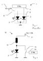
- Fig. 1 is a known from the prior art laser driver 1 with safety monitoring shown, in which by a safety controller 4 by means of a Montitordiode 2, which is monitored by the laser diode 3 emitted laser power.
- a safety controller 4 by means of a Montitordiode 2, which is monitored by the laser diode 3 emitted laser power.
- a further supply of power to the laser diode 3, for example by opening the switch 6, is suppressed.
- the monitor diode 2 is already accommodated by laser diode manufacturers in the same housing 5 as the laser diode 3 (although other output connections of the two elements are also common here).
- a supply voltage 7 (Vcc) greater than the laser threshold voltage (Vth) of the laser 3 is required, which is applied to the laser diode for emission of a pulse for the desired pulse duration.
- the analog output signal of the photodiode 2 must be evaluated and, if necessary, a shutdown when exceeding the safety limits.
- the shutdown can be done by disconnecting the supply by means of the switch 6, which advantageously represents a second, independent instance of the circuit which generates the laser pulses. Since this circuit part is safety-relevant, certain design regulations may apply, for example, a pure software solution of safety-relevant parts may be subject to impermissible or at least strict design regulations.
- Fig. 2 shows a safe laser driver 10 according to the invention for a pulsed operation of a laser diode, in which can be dispensed with respect to the single-error laser safety on a monitor diode.
- the supply voltage 11 (Vcc) of the laser diode 3 is designed such that it does not exceed the laser threshold voltage (Vth) of the laser diode 3.
- the lasing threshold voltage Vth is the voltage that drops across the laser diode 3 and in which the population inversion in the semiconductor is just high enough to begin stimulated emission (or "lasing").
- a laser threshold current may also be indicated in data sheets, but from this the person skilled in the art can determine in a known manner the voltage required for impressing this current, and thus limiting it.
- the laser diode 3 is in this embodiment with its cathode at zero potential GND and with its anode via an inductive component 12 with the supply voltage eleventh connected. Since the supply voltage 11 is too low to trigger a stimulated emission, the laser diode can emit a maximum generated by spontaneous emission lights, the intensity of which is below the allowable limits, in particular because it is not in such an emission to "laser light" in the actual Meaning. It is obvious that the arrangement of the components in functionally equivalent manner could also be carried out differently (for example horizontally mirrored with the inductance on the cathode side, etc.).
- the switching element 13 (which can be embodied, for example, as a transistor, especially as a field-effect transistor) is closed, the laser diode 3 likewise can not emit laser light.
- the laser diode is short-circuited by the switch, which is why the current flows through the switch and not via the laser diode 3.
- Another advantageous side effect can also be that the laser can be operated, for example, directly at a battery voltage below the laser threshold, without this voltage must first be raised above the threshold level by means of a specially necessary boost converter.
- the circuit according to the invention is designed for the delivery of pulsed laser radiation, in particular of pulse packets (bursts).
- pulse packets bursts
- Fig. 3 an exemplary flowchart of the laser pulse generation according to the invention is shown.
- the reference numerals in the electroschemes remain the same in each case and are shown only once for reasons of clarity.
- step 100 the switch 13 is closed. Shortly before the closing of the switch 13, the supply voltage V11, which is below the laser threshold voltage Vth, is applied to the series connection of the inductor 13 and the laser diode 3. Through the laser diode 3 and the inductor 12, the same current flows I3 and I12, which is very low due to the exponential current-voltage characteristic of the laser diode, below the threshold voltage Uth (or the threshold current Ith). In the laser diode there is too low population inversion, as a stimulated emission of laser light would be possible.
- a current 19 in the inductor 12 builds up as I12 according to the known one 1 - e - t ⁇ Function, which flows off via the switch 13.
- the laser diode 3 is short-circuited and both voltage U3 and current 13 are virtually zero. Thus, no light can be emitted.
- step 102 the switch 13 is opened.
- step 103 the current 19 now continues to flow in the inductor 12 due to the condition of continuity, but now as 13 via the laser diode 3 instead of via the now open switch 13.
- the voltage U3 across the laser diode 3 increases correspondingly over that of the laser threshold the laser diode emits laser light, which is symbolized by the now existing arrows 18.
- the switching times of the switch 13 can be selected freely from the pulse generator circuit 14, that is, for example, during the construction or degradation of the current 19, whereby, for example, the pulse shape and / or the pulse energy can be varied.
- the diagram in Fig. 4 shows exemplary current waveforms on the laser diode 3 as a graph 91 (solid line) and the inductive component 12 as a graph 92 (dotted line).
- the inductive component can be designed, for example, as a wound coil, as a correspondingly shaped strip conductor section or as an SMD inductance.
- An embodiment of the inductive component in the form of inductive transformer for example, similar to the basic structure of a flyback converter with the laser diode as a load, can also be used as a special form for Erzeilung the laser safety according to the invention without a monitor diode.
- the graph 90 shows the state of the switch 13, where ON is closed and OFF is open.
- the diode current is zero or at least below the laser threshold. Only after the opening of the switch, the current which has previously flowed through the inductor flows due to the continuity condition of the inductive component via the laser diode 3 until it has degraded or until the switch 13 is closed again. As shown in the second pulse, the pulse energy can also be varied by a shorter turn-on time of the switch 13, in which the current through the inductance 12 has not yet reached the saturation value. In contrast to a pulse energy variation approach with a normally closed switch, less current flows per pulse in total, which has a positive effect on the circuit's energy efficiency.
- the maximum possible pulse energy in case of failure of a too slowly clocked switch 13 to observe or an occurrence of such error by further measures accordingly to prevent.
- the shape of the generated optical pulse can be kept at least approximately the same as varying the duty cycle of the switch, and primarily only its peak and thus also the pulse energy can be varied, as well as the second pulse of the graph 92 and 92, respectively.
- the third illustrated pulse shows a saturation of the inductive component, which limits the maximum achievable pulse energy.
- the inductive time constant limits the maximum possible pulse repetition rate.
- Fig. 5a an embodiment is shown, in which, in addition to the extension of the security monitoring of the laser supply voltage to a possible threshold overshoot is made. If a voltage which lies above the laser tube is detected in an electrical network of the laser diode supply, a corresponding measure is taken to prevent emission of laser light.
- the exemplary measures shown are either a closing of the switch 13, whereby the laser diode 3 is short-circuited and in addition - or as an alternative - a disconnection of the supply 11 via another, independent switch 16.
- the disconnection of the supply can the entire laser system, the laser driver 10 or the laser diode 3 relate.
- the further switch 16 for safety shutdown those skilled in the art will also be familiar with other - functionally equivalent - possibilities, for example a low-side switch in the lower branch of the laser diode, etc.
- the circuit meets the safety regulations.
- a processor, communication blocks, etc. which operate at a level of, for example, 2.5V, 3.3V, 5V or 12V, which above the threshold voltage, for example from 1.8V to 2.2V at Infrared laser diodes, lies.
- the higher voltage can be reduced accordingly to supply the laser diode in a known manner with a linear or clocked voltage regulator.
- Fig. 5b and Fig. 5c are two examples of alternative arrangements of the components with which a laser diode driver according to the invention can be executed, wherein the skilled person further alternatives to the component arrangement are known with which the inventive principle can be realized.
- Fig. 6 shows a block diagram of a system with a control or communication processor 53, and a laser driver 10, which drives the laser diode 3 for the emission of light pulses.
- the processor 53 and the laser driver 10 are supplied by a system supply 11 which is above the laser threshold level.
- the laser driver 10 is exemplified as an ASIC.
- a series regulator 50 eg, an LDO
- LDO low-dropping diode
- An error case in which a short circuit between the system voltage 32 and the laser diode output 31 occurs is detected by the built-in short circuit detection circuit 51 (SCD) and signaled by a digital error signal 33 to the processor or microcontroller 53, for example via a digital signal or via a communication channel.
- the higher-level controller 53 can disconnect the now too high forward voltage via the switching element 16 from the coil 12 and the laser diode 3. At best, such a separation can also be triggered directly by the error signal 33. In other words, the separation of the laser diode 3 by the switch 16 is only canceled if the voltage at the laser diode output 31 is in the safe range below the laser threshold.
- the LDO additionally has an enable input 34, which additionally can prevent or allow the provision of the laser supply voltage. This can be used as a further safety circuit to prevent unwanted emission.
- the pulse generator 14 which controls the switch 13 and the pulse train (eg: on time, off time, pulse repetition rate, pulse duty cycle, burst duty cycle, burst repetition rate, pulses by burst, etc.).
- This can be configured and triggered via a communication interface (for example, single-wire, SSI, SPI, I2C, UART,...) Instead of or in addition to the lines 33/34 from the higher-level controller 53.
- the control of the switch 13, which is also integrated in the ASIC 10 in this representation, can be used, for example, as an (arbitrarily configurable) PWM signal for Generation of the desired output pulse train can be realized.
- the switch 13 for example a MOSFET transistor output, is connected to the laser diode in the manner previously described.
- the pulse shape of an emitted laser pulse achieved by the circuit does not meet the requirements of the application, then this can be adapted in many different ways.
- the pulse shape is determined from the indices of the inductive component (especially from the inductance value, but also from the parasitic parameters, such as series resistance, etc.).
- the inductance can also be replaced or supplemented by a more complex pulse-shaping network, for example by parallel and / or series arrangement of resistors and / or capacitors (whereby the inherently inductive character must be preserved due to the function).
- a pulse shaping network can also be introduced into the GND branch of the laser diode, for example.
- the pulse shape can be adjusted, for example, by switching the switch 13 again during the pulse emission, the end of the pulse can be "cut off", and thus the pulse shape can be trimmed more to a rectangle.
- the pulse width (determined by the OFF time and / or ON time of the switch 13) can also be used to set the output power of a pulse.
- a laser driver as shown in this embodiment, can also be produced in highly integrated form, for example in thick-film technology, thin-film technology or ASIC, wherein a reduced size also brings advantages with respect to the electromagnetic interference emission.
- the number of external connections required can be reduced to the obligatory supply connections, two laser diode outputs, as well as a communication interface to the higher-level processor (for example as two-line communication), optionally with an enable input and an error output.
- a trigger, clock, and / or phase reference signal may be added to the pulse generator 14.
- Fig. 7 shows an alternative to the previous circuit in which in case of failure, the supply voltage of the entire laser driver is separated by a switch 16 from the system voltage.
- the switch 16 may also be integrated in the laser driver 10.
- An integration of the processor 53 into a laser driver embodied as an ASIC would also be possible.
- inventive circuit or method described here is for example highly suitable for a laser rangefinder with burst-modulated laser radiation, according to the principle as for example in EP 01 957 668 is described. According to the invention can thereby Without the use of a monitor diode the criteria of laser safety are met, resulting in a more compact, less expensive and less complex overall system.
- the comparator 55 compares the voltage 31 with a maximum allowable value, which is below the laser threshold voltage, and outputs when exceeded a digital error signal 34, due to which a further supply of supply energy is prevented, for example, by the switch 16 shown in this figure, the inductive component 12 is designed in the form of an exemplary pulse-forming Nettechniks, as already explained above.
- the shape of the generated current / voltage pulse can be influenced, for example in order to protect the switch 13 from overloading or to adapt the optical pulse over its course over time.
- a variation and / or design of the pulse shaping network shown here by way of example to fulfill the application-specific requirements is familiar to the person skilled in the art or can be determined by a simulation or experimental setups.
Abstract
Description
Die Erfindung betrifft einen sicheren Lasertreiber nach dem Oberbegriff des Anspruchs 1 und ein Ansteuerverfahren für einen Halbleiterlaser, insbesondere ein Verfahren zur Erzeugung eines Laserpulses nach dem Oberbegriff des Anspruchs 10.The invention relates to a safe laser driver according to the preamble of
Die allgemeinen Richtlinien zur Lasersicherheit (beispielsweise nach EN 60825, ANSI Z136 oder entsprechend der "International Commission on Non-Ionizing Radiation Protection") verlangen, dass eine Laserlichtquelle nur derart betrieben werden darf, dass von ihr keine Gefahren ausgehen. Dabei sind - abhängig von der emittierten Wellenlänge - Grenzwerte der thermischen Leistungsdichte bzw. der Energiedichte einzuhalten. Die Augensicherheit ist bei Lasergeräten von primärer Bedeutung, da das Auge funktionsbedingt am empfindlichsten auf elektromagnetische Strahlung reagiert und durch direkte, indirekte oder gestreute Laserstrahlen Schädigungen der Netzhaut oder Hornhaut auftreten können. Dies gilt insbesondere, da Studien zeigten, dass auch bei sichtbarem Licht vom Lidschlussreflex zum Schutz des Auges im Regelfall nicht ausgegangen werden kann. Lasergeräte sind entsprechend dieser Vorschriften zu klassifizieren und entsprechend zu kennzeichnen, was gegebenenfalls auch eine Sicherheits-Prüfung und Zertifizierung umfassen kann.The general guidelines for laser safety (for example according to EN 60825, ANSI Z136 or according to the "International Commission on Non-Ionizing Radiation Protection") require that a laser light source only be operated in such a way that it poses no danger. Depending on the emitted wavelength, limit values of the thermal power density or the energy density must be observed. Eye safety is of primary importance to laser devices, as the eye reacts most sensitively to electromagnetic radiation due to its function, and damage to the retina or cornea can occur through direct, indirect or scattered laser beams. This is particularly true since studies have shown that even with visible light from the eyelid closure reflex to the protection of the eye can not be expected in the rule. Laser devices shall be classified and labeled in accordance with these requirements, which may include, as appropriate, safety testing and certification.
Bei einer Vielzahl von Laser-Geräte, beispielsweise elektrooptischen Vermessungsgeräten wie Laser-Distanzmesser oder Laser-Nivellierer, Laser-Projektor, Laser-Scanner, etc. ist funktionsbedingt ein Austritt des Laserlichts aus dem Gehäuse des Geräts zwingend erforderlich. Auch ist oftmals funktionsbedingt eine optische Mindestenergie erforderlich, welche über der Ungefährlichkeitsgrenze läge, wenn diese im Dauerstrichbetrieb emittieren würde. Daher werden die Laser in derartigen Geräten meist gepulst betrieben. Um die Augensicherheit zu garantieren, müssen die Laserquellen mit entsprechenden Schutzmaßnahmen ausgestattet sein, um die geltenden Normen und Vorschriften zu erfüllen. Dies gilt nicht nur im gewöhnlichen Betriebsfall, sondern auch unter so genannten "Einfehlerbedingungen", welche all jene Fehlerszenarien abdecken, bei welchen ein einziger Fehler für sich alleine auftritt (z.B. Versagen einzelner Bauteile, Kurzschluss, Leiterbahnbruch, etc.). Dabei muss beispielsweise auch bei Ausfall einer beliebigen Komponente sichergestellt werden, dass trotz auftreten eines solchen Einfachfehlers, die austretende Laserleitung innerhalb von Sekundenbruchteilen unter die obere Leistungsgrenze der entsprechenden Laserklasse abfällt, um Augenschäden auszuschließen. Bei Pulsbetrieb ist durch spezielle Maßnahmen darauf zu achten, das eine andauernde Emission mit den - über den Grenzwerten liegenden - Puls-Spitzenwerten auch im Fehlerfall ausgeschlossen werden kann. Derartige Single-Fault-Tests sind vom Hersteller des Lasergeräts entsprechend durchzuführen und nachzuweisen.In the case of a large number of laser devices, for example electro-optical measuring devices such as laser distance meters or laser levelers, laser projectors, laser scanners, etc., an exit of the laser light from the housing of the device is imperative due to the function. Also is often functionally a minimum optical energy which would be above the hazard limit if it emitted in CW operation. Therefore, the lasers are operated in such devices usually pulsed. To ensure eye safety, laser sources must be equipped with appropriate protective measures to comply with applicable standards and regulations. This applies not only in the normal operating case, but also under so-called "Einfehler conditions", which cover all those fault scenarios in which a single fault occurs by itself (eg failure of individual components, short circuit, conductor break, etc.). In this case, it must be ensured, for example, even in case of failure of any component that despite the occurrence of such a single error, the leaking laser line falls within fractions of a second below the upper limit of the corresponding laser class to exclude eye damage. In pulse mode, special measures must be taken to ensure that continuous emission with pulse peak values above the limit values can be excluded even in the event of a fault. Such single-fault tests are to be performed and verified by the manufacturer of the laser device accordingly.
Je nach Laserklasse und Anwendungsfall kann auch weitergehend eine Zwei- oder Mehrfehlersicherheit gefordert sein, bei welcher auch bei gleichzeitigem Auftreten von mehr als einem Fehler ein Nachweis der Sicherheit zu erbringen ist, dass die emittierte Laserleitung keinesfalls die Grenzwerte überschreitet und somit eine Gefährdung des Benutzers ausgeschlossen werden kann. Die in diesem Dokument beschriebene Einfehlersicherheit stellt auch in diesen Fällen eine jedenfalls zu erfüllende Basisvoraussetzung dar, welche durch entsprechende, weiterführende Maßnahmen ausgebaut werden kann.Depending on the laser class and application, a two- or Mehrfehlersicherheit may continue to be required, in which even with the simultaneous occurrence of more than one error proof of safety is to provide that the emitted laser line in any case exceeds the limits and thus precludes a risk to the user can be. The single-fault security described in this document also represents a basic requirement to be met in these cases which can be expanded by appropriate, further measures.
Die zur Herstellung der Lasersicherheit gebräuchliche Lösung ist die direkte Überwachung der emittierten Laserleistung mit Hilfe einer Monitordiode. Dabei wird ein Teil des emittierten Laserlichts auf ein photosensitives Element geleitet, beispielsweise eine Photodiode oder ein Phototransistor, welches ein lichtintensitätsabhängiges elektrisches Signal bereitstellt. Eine Überwachungsschaltung, beispielsweise in Form eines Mikrokontrollers oder eines (bei sicherheitsrelevanten Schaltungsteilen gegebenenfalls sogar vorgeschriebenen) diskreten Schaltkreises, kann somit die aktuell emittierte Laserleistung überwachen und gegebenenfalls bei Überschreitung eines Grenzwertes der emittierten Laserenergie bzw. Laserleistung den Laser abschalten.The customary solution for the production of laser safety is the direct monitoring of the emitted laser power with the aid of a monitor diode. In this case, a part of the emitted laser light is directed onto a photosensitive element, for example a photodiode or a phototransistor, which provides a light intensity-dependent electrical signal. A monitoring circuit, for example in the form of a microcontroller or a discrete circuit (possibly even prescribed for safety-relevant circuit parts) can thus monitor the currently emitted laser power and, if necessary, switch off the laser if a limit value of the emitted laser energy or laser power is exceeded.
Beispielsweise zeigen die Dokumente
Aufgrund der Allgemeinheit der Lasersicherheitsvorschriften bzw. auch aufgrund einer oft anwendungsbedingt erforderlichen Regelung der Ausgangsleistung der Laserdiode, sind eine Vielzahl der kommerziell erhältlichen Laserdioden-Bauelemente bereits mit einer entsprechenden Monitordiode ausgestattet. Laserdioden weisen zudem oft starke Exemplarstreuungen, Temperaturabhängigkeiten oder Alterungseffekte auf, welche durch Bestimmung der tatsächlichen optischen Ausgangsleistung ausgeglichen werden können. Der schaltungstechnische Aufwand einer derartigen Überwachung ist recht hoch und auch entsprechend kostenintensiv. Es bleibt somit der Aufwand, das analoge und oft störungsempfindliche Signal des - vielfach als Photodiode ausgeführten - photosensitiven Überwachungselements auszuwerten. Vielfach muss eine derartige Sicherheitsschaltung auch in einer entsprechend nachweislich sicheren und zertifizierbaren Weise ausgeführt werden, was den Schaltungsaufwand zusätzlich erhöhen kann, insbesondere da die Realisierung von sicherheitsrelevanten Schaltungsteilen oft an strenge Bedingungen und Dokumentationsvorschriften geknüpft ist.Due to the generality of the laser safety regulations or due to an often required application-dependent control of the output power of the laser diode, a plurality of commercially available laser diode components are already equipped with a corresponding monitor diode. In addition, laser diodes often have severe specimen scatters, temperature dependencies, or aging effects, which can be compensated for by determining the actual optical output power. The circuit complexity of such monitoring is quite high and also correspondingly expensive. Thus, it remains the effort to evaluate the analog and often noise-sensitive signal of the - often implemented as a photodiode - photosensitive monitoring element. In many cases, such a safety circuit must also be carried out in a correspondingly demonstrably safe and certifiable manner, which can additionally increase the circuit complexity, in particular since the realization of safety-relevant circuit parts is often linked to strict conditions and documentation regulations.
Zudem ist im Pulsbetrieb von Laserdioden, bei welchem nur sehr kurze Lichtimpulse mit einer hohen Spitzenleitung ausgesendet werden, bedingt durch die dabei in der elektronischen Schaltung auftretenden, steilen Schaltflanken und hohen Spitzenströmen, mit entsprechenden elektromagnetischen Störsignalen (Übersprechen, etc.) zu rechnen, welche die (meist hochohmige erfolgende) Auswertung der Messsignale einer Monitordiode stören und erschweren können. Auch kann die kurze Pulsdauer des emittierten Lichtes und der korrespondierenden Monitorsignale eine Überwachung der tatsächlich emittierten, mittleren Lichtenergie erschweren.In addition, in the pulsed operation of laser diodes, in which only very short light pulses are emitted with a high peak line, due to the occurring in the electronic circuit, steep switching edges and high peak currents, with corresponding electromagnetic interference signals (crosstalk, etc.) to be expected, which the (mostly high-impedance) evaluation of the measurement signals of a monitor diode can interfere with and complicate. Also, the short pulse duration of the emitted light and the corresponding monitor signals to make it difficult to monitor the actually emitted mean light energy.
Die Laserpulse werden dabei vielfach in Paketen von Pulsen, den so genannten "Bursts" emittiert, wie diese etwa in
Es ist daher eine Aufgabe der vorliegenden Erfindung die Ansteuerung einer Laserdiode, insbesondere unter Einhaltung der Sicherheitsvorschriften, zu verbessern.It is therefore an object of the present invention to improve the control of a laser diode, in particular in compliance with safety regulations.
Eine Aufgabe besteht auch darin, einen sicheren Lasertreiber für den Puls- oder Burst-Betrieb bereitzustellen, welcher einfacher und kostengünstiger realisierbar ist und beispielsweise einen geringern Bauteil- und Auswerteaufwand aufweist.It is also an object to provide a safe laser driver for pulse or burst operation, which is easier and less expensive to implement and, for example, has a lower component and evaluation effort.
Eine Teilaufgabe ist dabei auch einen Lasertreiber bereitzustellen, welcher in hochintegrierter Form herstellbar ist, neben einem klassischen Leiterplattenaufbau also beispielsweise auch in Dickschichttechnik, Dünnschichttechnik oder als ASIC.A sub-task is also to provide a laser driver, which can be produced in a highly integrated form, in addition to a classic printed circuit board construction, for example, in thick-film technology, thin-film technology or ASIC.
Eine Aufgabe ist auch die Lasersicherheit mit einer Schaltung zu erzielen, bei welcher im Sicherheitskreis keine analogen Monitorsignale eines photosensitiven Elements ausgewertet werden, insbesondere bei welcher keine Analog-zu-Digital Wandlung (ADC) notwendig ist.An object is also to achieve laser safety with a circuit in which no analog monitor signals of a photosensitive element are evaluated in the safety circuit, in particular in which no analog-to-digital conversion (ADC) is necessary.
Eine Teilaufgabe ist auch die sicherheitsgerechte Ansteuerung einer Laserdiode, welche weniger elektrische Anschlüsse aufweist als eine mit einer Monitordiode ausgestattete Laserdiode, insbesondere einer zweipoligen Laserdiode in SMD-Bauform.A partial task is also the safety-oriented control of a laser diode, which less electric Having terminals as a equipped with a monitor diode laser diode, in particular a two-pole laser diode in SMD design.
Auch die Entwicklung einer einfehlersicheren Lasertreiberschaltung welche ohne Monitordiode auskommt, ist eine Aufgabe der vorliegenden Erfindung.The development of a fail-safe laser driver circuit which manages without monitor diode, is an object of the present invention.
Ebenso das Bereitstellen eines Lasertreibers als ASIC, insbesondere mit einem rein digitalen Interface nach aussen, ist eine Aufgabe der vorliegenden Erfindung.Similarly, the provision of a laser driver ASIC, especially with a purely digital interface to the outside, is an object of the present invention.
Im Weiteren beschreiben wird ein erfindungsgemässer, sicherer Lasertreiber für einer Laserdiode zur Emission von Laserlichtpulsen mit einer Laserdioden-Spannungversorgung, zur Bereitstellung einer Spannung welche Unterhalb einer Laser-Threshold-Spannung der Laserdiode liegt. Dadurch ist bei statischem Anliegen der Spannung an der Laserdiode kein Laserlicht emittierbar.In the following, a safe laser driver according to the invention for a laser diode for emitting laser light pulses with a laser diode voltage supply will be described, for providing a voltage which lies below a laser threshold voltage of the laser diode. As a result, no laser light can be emitted when the voltage at the laser diode is static.
Der Lasertreiber hat weiters eine induktive Komponente in einem Versorgungspfad der Laserdiode, insbesondere elektrisch verbunden mit der Laserdiode, und ein elektronisches Schaltelement.The laser driver further has an inductive component in a supply path of the laser diode, in particular electrically connected to the laser diode, and an electronic switching element.
Das Schaltelement ist dabei derart zusammenwirkend angeordnet, dass in einer ersten statischen Schaltstellung des Schaltelements ein Stromfluss durch die induktive Komponente erzeugbar ist und in einer zweiten statischen Schaltstellung des Schaltelements der Stromfluss durch die Laserdiode leitbar ist. Im Speziellen mit der induktiven Komponente im Schaltkreis zwischen der Spannungsversorgung und der Laserdiode liegend und insbesondere mit einem zur Laserdiode elektrisch parallelgeschalteten Schaltelement. Lediglich bei einem Wechsel von der ersten zur zweiten Schaltstellung ist einer der Laserlichtpulse emittierbar. Ein einzelner der somit bei einem Wechsel von der ersten zur zweiten Schaltstellung emittierbaren Laserlichtpulse weist eine Energie auf, welche durch die in der induktiven Komponente aufgrund des Stromflusses gespeicherte Energie begrenzt ist und auch die mittlere emittierte Laserleistung einer Gruppe der Laserlichtpulse ist somit begrenzt ist. Insbesondere kann der Lasertreiber somit einen monitordiodenlosen Sicherheitskreis zur Einhaltung einer maximal zulässigen mittleren Laserleistung aufweisen.The switching element is arranged cooperatively such that in a first static switching position of the switching element, a current flow through the inductive component can be generated and in a second static switching position of the switching element, the current flow through the laser diode can be conducted. In particular, with the inductive component in the circuit between the power supply and the laser diode lying and in particular with a parallel to the laser diode in parallel switching element. Only with a change from the first to the second switching position, one of the laser light pulses is emitted. An individual of the laser light pulses which can thus be emitted when changing from the first to the second switching position has an energy which is limited by the energy stored in the inductive component due to the current flow and the mean emitted laser power of a group of the laser light pulses is thus limited. In particular, the laser driver can thus have a monitor-diode-free safety circuit for maintaining a maximum permissible average laser power.
Mit einem monitordiodenlosen Sicherheitskreis kann somit die Einhaltung einer maximal zulässigen Emissionsleistung, entsprechend der Lasersicherheitsrichtlinien gewährleistet werden, im Speziellen auch im Einfehlerfall, beispielsweise bei Ausfall oder Kurzschluss einer Komponente oder eines Bauelements des Lasertreibers.With a monitordiodenlosen safety circuit thus compliance with a maximum allowable emission performance, can be guaranteed in accordance with the laser safety guidelines, in particular in Ein Einfallfall, for example in case of failure or short circuit of a component or a component of the laser driver.
Eine Grundidee der vorliegenden Erfindung ist, dass die DC Vorwärtsspannung mit welcher die Laserdiode versorgt wird, unterhalb der Laserschwelle, des sogenannten Laserthresholds der Laserdiode liegt. Dies bedeutet, dass die Laserdiode im Gleichstromfall kein Laserlicht emittieren kann. Selbst bei direktem Anlegen der Versorgung zur Laserdiode (z.B. bei einem Kurzschluss), tritt keine stimulierte oder verstärkte Emission auf, sondern allenfalls nur eine schwache, spontane, nichtverstärkte Emission von Photonen, ähnlich einer Leuchtdiode. Somit ist in diesem Betriebs- bzw. Fehler-Zustand die Lasersicherheit gewährleistet.A basic idea of the present invention is that the DC forward voltage with which the laser diode is supplied lies below the laser threshold, the so-called laser threshold of the laser diode. This means that the laser diode can not emit laser light in the DC case. Even with direct application of the supply to the laser diode (eg in the case of a short circuit), no stimulated or amplified emission occurs, but at most only a weak, spontaneous, non-amplified emission of photons, similar to a light-emitting diode. Thus, the laser safety is guaranteed in this operating or error state.
Um im Pulsbetrieb dennoch Laserlicht emittieren zu können, befindet sich in einer zur Erläuterung herangezogenen, beispielhaften Ausführungsform in Serie zur Laserdiode eine induktiv wirkende Komponente und parallel zur Laserdiode ein Schaltelement, mit welchem die Laserdiode kurzgeschlossen werden kann. Der Ablauf zur Emission eines Laserpulses ist dabei wie folgt:
- 1. Ein Puls-Generator schließt den Schalter parallel zur Laserdiode. Dadurch liegt die Versorgungsspannung (welche wie beschrieben unterhalb des Laserthresholds liegt) an der induktiven Komponente an.
- 2. Es prägt sich ein Strom in der induktiven Komponente ein. Dieser fließt von der Spannungsquelle über die induktive Komponente und den Schalter nach Maße.
- 3. Der Puls-Generator öffnet den Schalter.
- 4. Da der Strom in der induktiven Komponente trotz offenem Schalter aber weiterhin bestehen bleibt, muss dieser nun durch die Laserdiode fließen. Es hebt sich das Potential an der Anode der Laserdiode über den Laserthreshold und die stimulierte Emission eines Laserpulses setzt ein. Die maximale Energie des Pulses ist dabei aber von der in der induktiven Komponente gespeicherten Energie beschränkt. Wenn sich der Strom abgebaut hat und die Spannung an der Anode der Laserdiode unter die Laserthreshold-Spannung gesunken ist, ist auch die Laser-Emission zu Ende.
- 5. Der Prozess kann sich bei Schritt 1 wiederholen.
- 1. A pulse generator closes the switch parallel to the laser diode. As a result, the supply voltage (which as described lies below the laser threshold) is applied to the inductive component.
- 2. A current is imprinted in the inductive component. This flows from the voltage source via the inductive component and the switch to dimensions.
- 3. The pulse generator opens the switch.
- 4. However, since the current in the inductive component remains open despite the open switch, it must now flow through the laser diode. The potential at the anode of the laser diode rises above the laser threshold and the stimulated emission of a laser pulse sets in. However, the maximum energy of the pulse is limited by the energy stored in the inductive component. When the current has dissipated and the voltage at the anode of the laser diode has dropped below the laserthreshold voltage, the laser emission is also over.
- 5. The process can be repeated at
step 1.
Die Laserpulse können somit als einzelne Pulse oder in Puls-Paketen (Bursts) oder als kontinuierliche Pulsfolge abgegeben werden. Zwischen den Pulsen oder Bursts kann der Schalter geschlossen oder offen bleiben. In beiden Fällen wird der Laser kein Licht abgeben.The laser pulses can thus be delivered as individual pulses or in bursts of pulses or as a continuous pulse train. Between the pulses or bursts of the Switch closed or left open. In both cases, the laser will not emit light.
Ist der Schalter offen, so baut sich ein allfälliger Strom in der induktiven Komponente über die Laserdiode ab und die Spannung über der Laserdiode fällt unter den Threshold (etwa auf das Niveau der Versorgungsspannung) ab. Da die Versorgungsspannung unter der Threshold-Spannung liegt, wird bei statisch offenem Schalter kein Laserlicht erzeugt. Somit ist in diesem statischen Betriebszustand keine Laseremission möglich.If the switch is open, a possible current in the inductive component breaks down via the laser diode and the voltage across the laser diode drops below the threshold (approximately to the level of the supply voltage). Since the supply voltage is below the threshold voltage, laser light is not generated when the switch is static open. Thus, no laser emission is possible in this static operating condition.
Ist der Schalter geschlossen, so fließt der Strom durch den Schalter und nicht durch die Laserdiode, wodurch in diesem statischen Betriebszustand ebenfalls keine Laseremission möglich ist. Die Laserdiode ist durch den Schalter kurzgeschlossen - somit sind die Spannung und der Strom an der Laserdiode annähernd Null, jedenfalls unter den Thresholdwerten.If the switch is closed, the current flows through the switch and not through the laser diode, whereby in this static operating state also no laser emission is possible. The laser diode is short-circuited by the switch - thus the voltage and current at the laser diode are nearly zero, at least below the threshold values.
Lediglich bei einem Wechsel von geschlossenem zu offenem Schalter ist eine Emission der Laserdiode möglich, aber auch hier mit einer definierten Obergrenze der möglichen Pulsenergie. Keinesfalls ist eine Dauerstrichemission von Laserlicht möglich.Only with a change from closed to open switch an emission of the laser diode is possible, but also here with a defined upper limit of the possible pulse energy. Under no circumstances is a continuous wave emission of laser light possible.
Die Laserleistung kann über die Anzahl Pulse pro Burst oder der Pulswiederholrate innerhalb des Burst eingestellt werden. Beispielsweise kann dies in der Produktion des Lasers oder assemblierten Lasergerätes im Rahmen einer Funktionsprüfung oder Kalibrierung ermittelt und eingestellt werden. Auch mittels einer Justierung des Tastverhältnisses des Pulsgenerators bei der Pulsgeneration kann die Energie eines Einzelpulses beeinflusst werden. Beispielsweise kann die Pulsenergie auch über die Zeitdauern der beiden Schaltzustände beim "Laden" bzw. "Entladen" der Induktivität beeinflusst werden. Es kann jedoch eine maximale Einzelpulsenergie nicht überschritten werden, welche sich aus dem Maximalstrom bei statisch geschlossenem Schalter und der damit verbundenen, in der Induktivität gespeicherten, Energiemenge bestimmt. Wenn beispielsweise die Parameter des Pulsgenerators anhand eines Schlimmstfall-Szenarios begrenzt werden, kann ein Überschreiten der Lasersicherheitsgrenzen in jedem Fall ausgeschlossen werden. Somit kann der erfindungsgemäße Lasertreiber derart ausgelegt werden, dass in jedem Fall die Lasersicherheit garantiert werden kann. Alterungseffekte machen den Laser lediglich ineffizienter, somit wird die Laserleistung mit der Zeit leicht abnehmen, aber auf keinen Fall die bei der Produktion eingestellte Grenze überschreiten. Ein altersbedingter Leistungsabfall könnte - falls notwendig - auch durch eine erneutes bestimmen der tatsächlich emittierten Leistung und Justage der Puls- bzw. Burst-Parameter kompensiert werden.The laser power can be adjusted by the number of pulses per burst or the pulse repetition rate within the burst. For example, this can be determined and set in the production of the laser or assembled laser device as part of a functional test or calibration. Also, by means of an adjustment of the duty cycle of the pulse generator in the pulse generation, the energy of a single pulse can be influenced. For example, the pulse energy can also be influenced over the periods of the two switching states when "charging" or "discharging" the inductance. However, a maximum single pulse energy can not be exceeded, which is determined from the maximum current at statically closed switch and the associated, stored in the inductance, amount of energy. If, for example, the parameters of the pulse generator are limited on the basis of a worst-case scenario, exceeding the laser safety limits can be ruled out in any case. Thus, the laser driver according to the invention can be designed so that in each case the laser safety can be guaranteed. Aging effects only make the laser inefficient, so the laser power will decrease slightly over time, but in no case will exceed the limit set during production. An age-related power loss could - if necessary - also be compensated by re-determining the actual emitted power and adjusting the pulse or burst parameters.
In einer weiterführenden Ausführungsform kann die Versorgungsspannung des Lasertreibers bzw. des gesamten Systems sehr wohl über der Laserthreshold-Spannung liegen. Dadurch wird beispielsweise eine Versorgung der peripheren Logikschaltungen, Prozessoren, Kommunikationsbausteine, etc. mit den hierfür gebräuchlichen, oft über der Laserschwelle liegenden Spannungen zu ermöglicht. Ein Tiefsetzsteller oder Längsregler (LDO) kann in diesem Falle die Laserdiode bzw. die davor geschaltete induktive Komponente, mit einer entsprechend niedrigeren, von der Versorgung unabhängigen geregelten Spannung versorgen, welche unter der Laserthreshold-Spannung liegt. Der Lasertreiber kann hierbei auch in Form eines ASICs ausgeführt sein, wobei der LDO sowohl extern angeordnet, als auch direkt im ASIC integriert sein kann.In a further embodiment, the supply voltage of the laser driver or of the entire system may very well be above the laser threshold voltage. As a result, for example, a supply of the peripheral logic circuits, processors, communication modules, etc. with the customary for this, often above the laser threshold voltages are possible. In this case, a step-down converter or series regulator (LDO) can supply the laser diode or the inductive component connected upstream with a correspondingly lower, supply-independent regulated voltage, which lies below the laser threshold voltage. Of the In this case, the laser driver can also be embodied in the form of an ASIC, wherein the LDO can be arranged both externally and integrated directly in the ASIC.
Bei einer solchen Ausführung, bei welcher Spannungen über dem Laserthreshold im oder um den Lasertreiber vorhanden sind, ist jedoch ein zusätzlicher Fehlerfall möglich, bei welchem die Sicherheit rein auf Basis der oben erläuterten, erfindungsgemäßen Schaltung bzw. Methode nicht mehr gewährleistet wäre, nämlich einen Kurzschluss zwischen der höheren Versorgung und einem elektrischen Netz in der Versorgung der Laserdiode.In such an embodiment, in which voltages are present above the laser threshold in or around the laser driver, however, an additional error case is possible, in which the security would not be guaranteed purely on the basis of the above-explained, inventive circuit or method, namely a short circuit between the higher supply and an electrical network in the supply of the laser diode.
Ein derartiger Kurzschluss kann durch eine zusätzliche Überwachung der Laserdiodenversorgungsspannung erkannt werden. Beispielsweise kann dies durch eine Kurzschluss-Detektionsschaltung (SCD) erkannt werden und mittels eines digitalen Signals an einen übergeordneten Mikrokontroller signalisiert oder direkt einer Sicherheitsabschaltung zugeführt werden. Die SCD kann dabei beispielsweise auch direkt in den LDO und/oder den Lasertreiber integriert sein, im Spezielle könnte etwa die am LDO auftretende Regelabweichung zum feststellen einer Überspannung herangezogen werden. Dieser kann im Fehlerfall die nunmehr zu hohe Vorwärtsspannung mittels eines zusätzlichen (unabhängigen) Schaltelements von der induktiven Komponente und/oder der Laserdiode trennen. Alternative kann durch das zusätzliche Schaltelement auch der ganze Lasertreiber von der - über dem Laserthreshold liegenden - Versorgungsspannung getrennt werden. Gegebenenfalls ist dabei eine zusätzliche Sicherungseinrichtung gegen automatisches Wiedereinschalten vorzusehen.Such a short circuit can be detected by additional monitoring of the laser diode supply voltage. For example, this can be detected by a short-circuit detection circuit (SCD) and signaled by a digital signal to a higher-level microcontroller or fed directly to a safety shutdown. For example, the SCD can also be integrated directly into the LDO and / or the laser driver; in particular, the control deviation occurring at the LDO could be used to determine an overvoltage. In the event of a fault, this can disconnect the now too high forward voltage by means of an additional (independent) switching element from the inductive component and / or the laser diode. Alternatively, the entire laser driver can be separated from the supply voltage lying above the laser threshold by the additional switching element. If necessary, an additional safety device against automatic restart is provided.
Alternativ kann die Laserdiodenversorgungsspannung auch durch eine Spannungsmessung, eine Komparatorschaltung oder dergleichen überwacht werden. Auch bezüglich der zusätzlichen Abschaltung im Fehlerfall gibt es funktionell äquivalente Alternativlösungen, mit welchen ebenfalls die geforderten Sicherheitsbedingungen erfüllt werden können.Alternatively, the laser diode supply voltage may also be monitored by a voltage measurement, a comparator circuit, or the like. Also with regard to the additional shutdown in the event of a fault, there are functionally equivalent alternative solutions, with which also the required safety conditions can be met.
Das erfindungsgemäße Verfahren und die erfindungsgemäße Vorrichtung werden nachfolgend anhand von konkreten Ausführungsbeispielen, welche in den Zeichnungen schematisch dargestellt sind, rein beispielhaft näher beschrieben. Dabei wird auch auf weitere Vorteile der Erfindung eingegangen. Im Einzelnen zeigen:
- Fig. 1
- ein Schema einer im Stand der Technik gebräuchlichen Laserdiode mit einer Monitordiode zur Sicherstellung bzw. Überwachung der Lasersicherheit;
- Fig. 2
- ein Elektronik-Schema einer ersten Ausführungsform eines erfindungsgemässen Lasertreibers zur Erläuterung des Grundprinzips;
- Fig. 3
- ein beispielhaftes Ablaufschema einer erfindungsgemässen Laserpulserzeugung;
- Fig. 4
- ein Diagramm eines beispielhaften Strom-Spannungsverlaufs bei einem erfindungsgemässen Lasertreiber.
- Fig. 5a
- ein beispielhaftes Elektronik-Schema einer zweiten Ausführungsform eines erfindungsgemässen Lasertreibers mit einer Versorgungsspannungsüberwachung;
- Fig. 5b
- ein Elektronik-Schema einer ersten beispielhaften alternativen Anordnung der Komponenten in einem erfindungsgemässen Lasertreiber;
- Fig. 5c
- ein Elektronik-Schema einer zweiten beispielhaften alternativen Anordnung der Komponenten in einem erfindungsgemässen Lasertreiber;
- Fig. 6
- ein beispielhaftes Blockschaltbild einer dritten Ausführungsform eines erfindungsgemässen Lasertreibers in grösserem Kontext;
- Fig. 7
- ein beispielhaftes Blockschaltbild einer vierten Ausführungsform eines erfindungsgemässen Lasertreibers mit alternativer Überspannungs-Abschaltung;
- Fig. 8
- ein beispielhaftes Blockschaltbild einer fünften Ausführungsform eines erfindungsgemässen Lasertreibers mit alternativer Überspannungs-Abschaltung und einem Pulsformungs-Netzwerk;
- Fig. 1
- a schematic of a conventional in the art laser diode with a monitor diode for ensuring or monitoring the laser safety;
- Fig. 2
- an electronic diagram of a first embodiment of a laser driver according to the invention for explaining the basic principle;
- Fig. 3
- an exemplary flowchart of a laser pulse generation according to the invention;
- Fig. 4
- a diagram of an exemplary current-voltage curve in a laser driver according to the invention.
- Fig. 5a
- an exemplary electronic scheme of a second embodiment of a laser driver according to the invention with a supply voltage monitoring;
- Fig. 5b
- an electronic diagram of a first exemplary alternative arrangement of the components in a laser driver according to the invention;
- Fig. 5c
- an electronic scheme of a second exemplary alternative arrangement of the components in a laser driver according to the invention;
- Fig. 6
- an exemplary block diagram of a third embodiment of a laser driver according to the invention in a larger context;
- Fig. 7
- an exemplary block diagram of a fourth embodiment of a laser driver according to the invention with alternative overvoltage shutdown;
- Fig. 8
- an exemplary block diagram of a fifth embodiment of an inventive laser driver with alternative overvoltage shutdown and a pulse shaping network;
In
Zur Überwachung durch den Sicherheits-Controller 4 muss das analoge Ausgangssignal der Photodiode 2 ausgewertet werden und gegebenenfalls bei überschreiten der Sicherheitsgrenzen eine Abschaltung erfolgen. Beispielsweise kann die Abschaltung durch Trennen der Versorgung mittels des Schalters 6 erfolgen, welcher vorteilhaft eine zweite, unabhängige Instanz zu jener Schaltung darstellt, welche die Laserpulse generiert. Da dieser Schaltungsteil sicherheitsrelevant ist, können gewisse Designvorschriften gelten, beispielsweise kann eine reine Softwarelösung von sicherheitsrelevanten Teilen unzulässig oder zumindest strengen Designvorschriften unterworfen sein.For monitoring by the
Wie bereits zuvor erläutert, ist dabei die Versorgungsspannung 11 (Vcc) der Laserdiode 3 derart ausgelegt, dass diese die Laserschwellen-Spannung (Vth) der Laserdiode 3 nicht übersteigt. Die Laserschwellen-Spannung Vth ist jene Spannung, welche über der Laserdiode 3 abfällt, und bei der die Besetzungsinversion im Halbleiter gerade derart hoch ist, dass eine stimulierte Emission (oder das "Lasern") beginnt. Alternativ zur Threshold-Spannung ist in Datenblättern gegebenenfalls auch ein Laser-Threshold-Strom angegeben, woraus der Fachmann jedoch in bekannter Weise die zur Einprägung dieses Stromes notwendige - und somit limitierende - Spannung bestimmen kann.As already explained above, the supply voltage 11 (Vcc) of the
Die Laserdiode 3 ist in dieser Ausführungsform mit ihrer Kathode auf Null-Potential GND und mit ihrer Anode über eine induktive Komponente 12 mit der Versorgungsspannung 11 verbunden. Da die Versorgungsspannung 11 zu niedrig ist um eine stimulierte Emission auszulösen, kann die Laserdiode maximal ein durch spontane Emission erzeugtes Leuchten abgeben, dessen Intensität jedenfalls unterhalb der zulässigen Grenzwerte liegt, insbesondere da es sich bei einer derartigen Emission auch nicht um "Laserlicht" im eigentlichen Sinne handelt. Es ist offensichtlich, dass die Anordnung der Komponenten in funktionell äquivalenter Weise auch anders, (beispielsweise horizontal gespiegelt mit der Induktivität auf der Kathodenseite, etc.) ausgeführt werden könnte.The
Ist das Schaltelement 13 (welches beispielsweise als Transistor ausgeführt sein kann, speziell als Feldeffekttransistor) geschlossen, kann die Laserdiode 3 ebenfalls kein Laserlicht emittieren. Die Laserdiode ist vom Schalter kurzgeschlossen, weshalb der Strom über den Schalter und nicht über die Laserdiode 3 fließt.If the switching element 13 (which can be embodied, for example, as a transistor, especially as a field-effect transistor) is closed, the
Ein weiterer vorteilhafter Nebeneffekt kann dabei auch sein, dass der Laser beispielsweise direkt an einer Batteriespannung unterhalb des Laserthresholds betrieben werden kann, ohne dass diese Spannung erst mittels eines eigens dafür nötigen Hochsetzstellers über den Threshold-Pegel angehoben werden muss.Another advantageous side effect can also be that the laser can be operated, for example, directly at a battery voltage below the laser threshold, without this voltage must first be raised above the threshold level by means of a specially necessary boost converter.
Die erfindungsgemäße Schaltung ist zur Abgabe von gepulster Laserstrahlung, insbesondere von Pulspaketen (Bursts), ausgelegt. In
In Schritt 100 wird der Schalter 13 geschlossen. Kurz vor dem Schließen des Schalters 13 liegt die Versorgungsspannung V11, welche unter Laser Threshold-Spannung Vth liegt, an der Serienschaltung der Induktivität 13 und der Laserdiode 3 an. Durch die Laserdiode 3 und die Induktivität 12 fließt derselbe Strom I3 bzw. I12, welcher aufgrund der exponentiellen Strom-Spannungskennlinie der Laserdiode, unterhalb der Threshold-Spannung Uth (bzw. des Threshold-Stroms Ith) sehr gering ist. In der Laserdiode herrscht eine zu niedrige Besetzungsinversion, als das eine stimulierte Emission von Laserlicht möglich wäre.In
Nach dem Schließen des Schalters 13 liegt die Versorgungsspannung V11, an der Induktivität 13 als Spannung V12 an.After closing the
Wie in Schritt 101 dargestellt, baut sich ein Strom 19 in der Induktivität 12 als I12 nach der bekannten 
Funktion auf, welcher über den Schalter 13 abfließt. Die Laserdiode 3 ist dabei kurzgeschlossen und sowohl Spannung U3 als auch Strom 13 sind praktisch Null. Somit kann kein Licht emittiert werden.As shown in
Function, which flows off via the
In Schritt 102 wird der Schalter 13 geöffnet.In
Wie in Schritt 103 gezeigt, fließt nunmehr der Strom 19 aufgrund der Stetigkeitsbedingung in der Induktivität 12 weiter, nunmehr aber als 13 über die Laserdiode 3 statt über den nun geöffneten Schalter 13. Die Spannung U3 über der Laserdiode 3 erhöht sich entsprechend über jene der Laserschwelle - die Laserdiode emittiert Laserlicht, welches durch die nunmehr vorhandenen Pfeile 18 symbolisiert wird.As shown in
Da der Strom nunmehr - nach einer 
Funktion - abklingt bis der Gleichgewichtszustand erreicht ist, bei welchem der Spannungspegel U12 in etwa der Versorgung U11 entspricht - also unter der Laserschwelle Uth liegt und entsprechend der Strom I3 durch die Laserdiode 3 unter den zugehörigen Schwellenstrom Ith gefallen ist. Nun wird auch kein Laserlicht 18 mehr emittiert.Since the current now - after a
Function - decays until the equilibrium state is reached, in which the voltage level U12 corresponds approximately to the supply U11 - that is below the laser threshold Uth and accordingly the current I3 has fallen through the
Die Schaltzeitpunkte des Schalters 13 können dabei frei von der Pulsgenerator-Schaltung 14 gewählt werden, also beispielsweise auch während des Aufbauens oder Abbauens des Stromes 19, wodurch beispielsweise die Pulsform und/oder die Pulsenergie variiert werden können.The switching times of the
Die erfindungsgemäße Laserpulsgenerationsmethode oder Verfahren zur Erzeugung eines Laserpulses mittels einer Laserdiode, lässt sich in anderen Worten beschreiben mit:
- ● Einem Versorgen der Laserdiode über eine induktive Komponente mit einer Versorgungsspannung, welche unterhalb einer Laserthreshold-Spannung der Laserdiode liegt;
- ● Einem Aufbauen eines Stromes durch die induktive Komponente durch Schließen eines parallel zur Laserdiode angeordneten Schaltelements;
- ● einem Abbauen des Stromes über die Laserdiode unter Emission des Laserpulses bei Öffnen des Schaltelements.
- ● supplying the laser diode via an inductive component with a supply voltage which is below a laser threshold voltage of the laser diode;
- ● establishing a current through the inductive component by closing a switching element arranged parallel to the laser diode;
- ● a reduction of the current via the laser diode with emission of the laser pulse when opening the switching element.
Das Diagramm in
In
Eine derartige Ausführungsform erlaubt auch das Vorhandensein von Spannungen über der Laserthreshold-Spannung imSuch an embodiment also allows for the presence of voltages above the laserthreshold voltage in the
Gerät oder auf dem Lasertreiber. Selbst im Fehlerfall eines Kurzschlusses der kritischen Versorgungsspannung zu einem elektrischen Netz der Laserdiode genügt die Schaltung dabei den Sicherheitsvorschriften. Beispielsweise falls auf derselben Leiterplatte Logikelemente, ein Prozessor, Kommunikationsbausteine, etc. vorhanden sind, welche mit einem Pegel von bspw. 2.5V, 3.3V, 5V oder 12V arbeiten, welcher über der Threshold-Spannung, beispielsweise von 1.8V bis 2.2V bei Infrarot-Laserdioden, liegt.Device or on the laser driver. Even in case of failure of a short circuit of the critical supply voltage to an electrical network of the laser diode, the circuit meets the safety regulations. For example, if on the same circuit board logic elements, a processor, communication blocks, etc. are present, which operate at a level of, for example, 2.5V, 3.3V, 5V or 12V, which above the threshold voltage, for example from 1.8V to 2.2V at Infrared laser diodes, lies.
Die höhere Spannung kann dabei zur Versorgung der Laserdiode in bekannter Weise mit einem linearen oder getakteten Spannungsregler entsprechend heruntergesetzt werden.The higher voltage can be reduced accordingly to supply the laser diode in a known manner with a linear or clocked voltage regulator.
In
In diesem Ausführungsbeispiel ist der Lasertreiber 10 beispielhaft als ASIC ausgeführt. Ein Längsregler 50 (z.B. ein LDO) im Lasertreiber-ASIC 10 versorgt den Laserdiodenausgang 31 mit einer konstanten, von der Systemspannung 32 unabhängigen Spannung, die unter der Laserthreshold-Spannung liegt.In this embodiment, the
Ein Fehlerfall bei welchem ein Kurzschluss zwischen Systemspannung 32 und dem Laserdiodenausgang 31 auftritt, wird durch die eingebaute Kurzschluss-Detektions-Schaltung 51 (SCD) erkannt und mittels eines digitalen Fehlersignals 33 an den Prozessor oder Mikrokontroller 53 signalisiert, beispielsweise über ein digitales Signal oder über einen Kommunikationskanal. Der übergeordnete Controller 53 kann die nun zu hohe Vorwärtsspannung über das Schaltelement 16 von der Spule 12 und der Laserdiode 3 trennen. Allenfalls kann eine solche Trennung auch direkt durch das Fehlersignal 33 ausgelöst werden. Anders gesagt wird die Trennung der Laserdiode 3 durch den Schalter 16 nur aufgehoben, falls die Spannung am Laserdiodenausgang 31 im sicheren Bereich unterhalb der Laserschwelle liegt.An error case in which a short circuit between the
In der dargestellten Ausführungsform verfügt der LDO zusätzlich über einen Freigabe-Eingang 34, welcher zusätzlich die Bereitstellung der Laserversorgungsspannung unterbindet bzw. erlauben kann. Dieser kann als weiterführende Sicherheitsschaltung zur Verhinderung einer unerwünschten Emission genutzt werden.In the illustrated embodiment, the LDO additionally has an enable
Weiters im beispielhaften Lasertreiber-Asic enthalten ist der Puls-Generator 14, welcher den Schalter 13 ansteuert und die Pulsfolge (z.B.: Ein-Zeit, Aus-Zeit, Puls-Repetitionsrate, Puls-Tastverhältnis, Burst-Tastverhältnis, Burst-Repetitionsrate, Pulse per Burst, etc.) bestimmt. Dieser kann über eine Kommunikationsschnittstelle (beispielsweise Eindraht-, SSI, SPI, I2C, UART, ...) anstelle oder zusätzlich zu den Leitungen 33/34 vom übergeordneten Controller 53 aus konfiguriert und ausgelöst werden. Die Ansteuerung des Schalters 13, welcher in dieser Darstellung ebenfalls im ASIC 10 integriert ist, kann beispielsweise als ein (beliebig konfigurierbares) PWM-Signal zur Erzeugung der gewünschten Ausgangspulsfolge realisiert werden.Further included in the exemplary laser driver Asic is the
Der Schalter 13, beispielsweise ein MOSFET-Transistor-Ausgang, ist mit der Laserdiode in der zuvor beschriebenen weise verbunden.The
Falls die durch die Schaltung erzielte Pulsform eines emittierten Laser-Pulses nicht den Erfordernissen der Anwendung entspricht, so kann diese auf verschiedenste Weise angepasst werden. Zum einen bestimmt sich die Pulsform aus den Kennzahlen der induktiven Komponente (speziell aus dem Induktivitätswert, aber auch aus den parasitären Parametern, wie Serienwiderstand, etc.). In weiterer Folge kann die Induktivität auch durch ein komplexeres Puls-Formungs-Netzwerk ersetzt oder ergänzt werden, beispielsweise durch parallel und/oder Serienanordnung von Widerständen und/oder Kondensatoren (wobei funktionsbedingt der grundsätzlich induktive Charakter erhalten bleiben muss). Ein solches Puls-Formungs-Netzwerk kann beispielsweise auch in den GND-Zweig der Laserdiode eingebracht werden.If the pulse shape of an emitted laser pulse achieved by the circuit does not meet the requirements of the application, then this can be adapted in many different ways. On the one hand, the pulse shape is determined from the indices of the inductive component (especially from the inductance value, but also from the parasitic parameters, such as series resistance, etc.). Subsequently, the inductance can also be replaced or supplemented by a more complex pulse-shaping network, for example by parallel and / or series arrangement of resistors and / or capacitors (whereby the inherently inductive character must be preserved due to the function). Such a pulse shaping network can also be introduced into the GND branch of the laser diode, for example.
Zudem kann auch durch eine entsprechende Ansteuerung des Schaltelements 13 die Pulsform angepasst werden, beispielsweise kann durch erneutes Einschalten des Schalters 13 noch während der Pulsemission, das Ende des Pulses "abgeschnitten" werden, und somit die Pulsform mehr zu einem Rechteck getrimmt werden. Über die Pulsbreite (bestimmt durch die OFF-Zeit und/oder ON-Zeit des Schalters 13) kann auch die Ausgangsleistung eines Pulses eingestellt werden. Bei entsprechend schnellem Pulsgenerator kann auch eine PWM-Modulation innerhalb eines Pulses erreicht werden, wodurch, insbesondere bei entsprechender Glättung der PWM Modulation innerhalb des Pulses durch das Pulsformungsnetzwerk, die Form des emittierten Pulses (Intensitätsprofil über der Zeit) und/oder die Pulsenergie konfigurierbar ist.In addition, by appropriate control of the switching
Ein Lasertreiber, wie er in dieser Ausführungsform dargestellt ist, lässt sich zudem in hoch integrierter Form herstellen, beispielsweise in Dickschichttechnik, Dünnschichttechnik oder als ASIC, wobei eine reduzierte Baugrösse auch Vorteile bezüglich der elektromagnetischen Störaussendung bringt. Zudem lässt sich die Anzahl der erforderlichen externen Anschlüsse auf die obligatorischen Versorgungsanschlüsse, zwei Laserdiodenausgänge, sowie einer Kommunikationsschnittstelle zum übergeordneten Prozessor (bspw. als Zweileiterkommunikation), gegebenenfalls mit einem Freigabe-Eingang und einem Fehler-Ausgang reduzieren. Falls es die Anwendung erfordert kann zudem noch ein Auslöse-, Takt-, und/oder Phasenreferenzsignal für den Pulsgenerator 14 hinzukommen.A laser driver, as shown in this embodiment, can also be produced in highly integrated form, for example in thick-film technology, thin-film technology or ASIC, wherein a reduced size also brings advantages with respect to the electromagnetic interference emission. In addition, the number of external connections required can be reduced to the obligatory supply connections, two laser diode outputs, as well as a communication interface to the higher-level processor (for example as two-line communication), optionally with an enable input and an error output. In addition, if the application requires it, a trigger, clock, and / or phase reference signal may be added to the
Die hier beschriebene erfindungsgemäße Schaltung bzw. Methode eignet sich beispielsweise in hohem Masse für einen Laserentfernungsmesser mit Burst-Modulierter Laserstrahlung, nach dem Prinzip wie dies beispielsweise in
Claims (15)
die Spannungsüberwachungsschaltung (15,51,55) durch eine Kurzschluss-Detektions-Schaltung eines Spannungsreglers (50), insbesondere eines Tiefsetzstellers, im Speziellen eines Low Drop-Out Längsreglers, erfolgt.Laser driver according to claim 2, characterized in that
the voltage monitoring circuit (15,51,55) by a short-circuit detection circuit of a voltage regulator (50), in particular a buck converter, in particular a low drop-out longitudinal regulator takes place.
gekennzeichnet durch
ein weiteres Schaltelement (16) zur Trennung des Versorgungspfades der Laserdiode oder des gesamten Lasertreibers (10) sodass kein Laserlicht (18) emittierbar ist, insbesondere wobei das weitere Schaltelement (16) anhand der Detektion der Spannungsüberwachungsschaltung (15,51) angesteuert wird.Laser driver according to one of the preceding claims,
marked by
a further switching element (16) for separating the supply path of the laser diode or the entire laser driver (10) so that no laser light (18) is emissive, in particular wherein the further switching element (16) is driven by the detection of the voltage monitoring circuit (15,51).
gekennzeichnet durch
ein weiteres Schaltelement (16) zum Kurzschluss der Laserdiode (3) sodass kein Laserlicht (18) emittierbar ist, insbesondere wobei das weitere Schaltelement (16) anhand der Detektion der Spannungsüberwachungsschaltung (15,51) angesteuert wird.Laser driver according to one of claims 1 to 3,
marked by
a further switching element (16) for short-circuiting the laser diode (3) so that no laser light (18) can be emitted, in particular wherein the further switching element (16) is controlled on the basis of the detection of the voltage monitoring circuit (15, 51).
dadurch gekennzeichnet, dass
die induktive Komponente (12) in Form eines Puls-Formungs-Netzwerks zur Formung der emittierten Laserlichtpulse (18) ausgeführt ist, insbesondere wobei dieses ein dominant induktives Verhalten zeigt.Laser driver according to one of the preceding claims,
characterized in that
the inductive component (12) in the form of a pulse shaping network for shaping the emitted Laser light pulses (18) is executed, in particular where this shows a dominant inductive behavior.
dadurch gekennzeichnet, dass
das Schaltelement (13) zur Laserpulsemission von einer konfigurierbaren Pulsweitenmodulations-Einheit (14) angesteuert wird, insbesondere wobei durch die Pulsweitenmodulation die Energie des
Laserlichtpulses (18) und/oder ein Intensitätsprofil des Laserlichtpulses (18) konfigurierbar ist.Laser driver according to one of the preceding claims,
characterized in that
the switching element (13) is driven for laser pulse emission by a configurable pulse width modulation unit (14), in particular wherein the energy of the pulse width modulation
Laser light pulse (18) and / or an intensity profile of the laser light pulse (18) is configurable.
dadurch gekennzeichnet, dass
der Lasertreiber (10) mit Ausnahme der Laserdiode (3) und der induktiven Komponente (12) als ASIC, insbesondere mit einem rein digitalen Ansteuerungs-Interface, ausgeführt ist.Laser driver according to one of the preceding claims,
characterized in that
the laser driver (10) with the exception of the laser diode (3) and the inductive component (12) ASIC, in particular with a purely digital drive interface, is executed.
gekennzeichnet durch,
ein detektieren eines Fehlerfalls durch ein überwachen der Versorgungsspannung (11,31) auf erreichen oder übersteigen einer vorgegebenen Spannungsgrenze, insbesondere der Laserthreshold-Spannung.Method according to the preceding claim,
marked by,
detecting a fault by monitoring the supply voltage (11,31) to reach or exceed a predetermined voltage limit, in particular the laser threshold voltage.
gekennzeichnet durch,
ein Trennen der oder Kurzschließen der Laserdiode (3) mittels eines weiteren Schaltelements (13) im Fehlerfall.Method according to the preceding claim,
marked by,
a disconnection or short-circuiting of the laser diode (3) by means of a further switching element (13) in the event of a fault.
das Überwachen durch eine Kurzschlussdetektion an einer die Versorgungsspannung herabsetzenden Schaltung erfolgt, insbesondere an einem herabsetzenden Festspannungsregler.Method according to one of claims 10 or 11, characterized in that
the monitoring by a short circuit detection takes place at a circuit which reduces the supply voltage, in particular at a decreasing fixed voltage regulator.
Priority Applications (6)
| Application Number | Priority Date | Filing Date | Title |
|---|---|---|---|
| EP11180282.3A EP2568547B1 (en) | 2011-09-06 | 2011-09-06 | Monitor diode-free laser driver |
| EP12753996.3A EP2753898B1 (en) | 2011-09-06 | 2012-09-04 | Electro-optical distance-measuring device |
| CN201280043193.8A CN103857983B (en) | 2011-09-06 | 2012-09-04 | Electrical-optical distance-measuring device |
| PCT/EP2012/067229 WO2013034555A1 (en) | 2011-09-06 | 2012-09-04 | Electro-optical distance measuring device |
| US14/343,024 US9817122B2 (en) | 2011-09-06 | 2012-09-04 | Electro-optical distance measuring device |
| US14/135,414 US9753139B2 (en) | 2011-09-06 | 2013-12-19 | Electro-optical distance measuring device |
Applications Claiming Priority (1)
| Application Number | Priority Date | Filing Date | Title |
|---|---|---|---|
| EP11180282.3A EP2568547B1 (en) | 2011-09-06 | 2011-09-06 | Monitor diode-free laser driver |
Publications (2)
| Publication Number | Publication Date |
|---|---|
| EP2568547A1 true EP2568547A1 (en) | 2013-03-13 |
| EP2568547B1 EP2568547B1 (en) | 2014-04-16 |
Family
ID=46796609
Family Applications (2)
| Application Number | Title | Priority Date | Filing Date |
|---|---|---|---|
| EP11180282.3A Active EP2568547B1 (en) | 2011-09-06 | 2011-09-06 | Monitor diode-free laser driver |
| EP12753996.3A Active EP2753898B1 (en) | 2011-09-06 | 2012-09-04 | Electro-optical distance-measuring device |
Family Applications After (1)
| Application Number | Title | Priority Date | Filing Date |
|---|---|---|---|
| EP12753996.3A Active EP2753898B1 (en) | 2011-09-06 | 2012-09-04 | Electro-optical distance-measuring device |
Country Status (4)
| Country | Link |
|---|---|
| US (2) | US9817122B2 (en) |
| EP (2) | EP2568547B1 (en) |
| CN (1) | CN103857983B (en) |
| WO (1) | WO2013034555A1 (en) |
Cited By (2)
| Publication number | Priority date | Publication date | Assignee | Title |
|---|---|---|---|---|
| US9677883B2 (en) | 2011-12-01 | 2017-06-13 | Leica Geosystems Ag | Distance measuring device |
| CN111999686A (en) * | 2020-07-25 | 2020-11-27 | 苏州浪潮智能科技有限公司 | Device and method for improving buckle plate communication stability |
Families Citing this family (28)
| Publication number | Priority date | Publication date | Assignee | Title |
|---|---|---|---|---|
| EP2589980A1 (en) | 2011-11-04 | 2013-05-08 | Leica Geosystems AG | Distance sensor |
| US10097908B2 (en) * | 2014-12-31 | 2018-10-09 | Macom Technology Solutions Holdings, Inc. | DC-coupled laser driver with AC-coupled termination element |
| US10158211B2 (en) * | 2015-09-22 | 2018-12-18 | Analog Devices, Inc. | Pulsed laser diode driver |
| US10193304B2 (en) * | 2016-07-01 | 2019-01-29 | Intel Corporation | Failsafe pulsed laser driver |
| DE102016115493A1 (en) * | 2016-08-22 | 2018-02-22 | Osram Gmbh | MONITORING OF OPTICAL CONVERTER |
| EP3507924A4 (en) | 2016-08-30 | 2020-04-08 | MACOM Technology Solutions Holdings, Inc. | Driver with distributed architecture |
| JP6942452B2 (en) * | 2016-09-09 | 2021-09-29 | 日本信号株式会社 | Distance measuring device |
| US10574026B2 (en) * | 2017-03-23 | 2020-02-25 | Infineon Technologies Ag | Circuit and method for driving a laser diode |
| US10630052B2 (en) | 2017-10-04 | 2020-04-21 | Macom Technology Solutions Holdings, Inc. | Efficiency improved driver for laser diode in optical communication |
| DE102017219413B4 (en) * | 2017-10-30 | 2021-11-04 | Robert Bosch Gmbh | Method for generating a laser pulse |
| US10903621B2 (en) | 2018-01-22 | 2021-01-26 | Argo AI, LLC | Circuit for driving a laser and method therefor |
| DE102018201508B4 (en) | 2018-02-01 | 2021-03-18 | Robert Bosch Gmbh | Use in a LiDAR system of a method for operating a LiDAR system by emitting laser light in the form of laser pulses |
| US11585909B2 (en) * | 2018-11-02 | 2023-02-21 | Waymo Llc | Laser safety comparator |
| US11005573B2 (en) | 2018-11-20 | 2021-05-11 | Macom Technology Solutions Holdings, Inc. | Optic signal receiver with dynamic control |
| US11808892B2 (en) | 2019-04-19 | 2023-11-07 | Lumentum Operations Llc | Methods for driving optical loads and driver circuits for optical loads |
| US11070026B2 (en) | 2019-07-19 | 2021-07-20 | Analog Devices International Unlimited Company | High current nanosecond laser driver circuit with wide pulse-width adjustment range |
| EP3994493A1 (en) * | 2019-08-07 | 2022-05-11 | Velodyne Lidar USA, Inc. | Apparatus and methods for safe pulsed laser operation |
| US11075502B2 (en) | 2019-08-29 | 2021-07-27 | Analog Devices, Inc. | Laser diode driver circuit techniques |
| US11600966B2 (en) * | 2020-02-03 | 2023-03-07 | Analog Devices International Unlimited Company | Light source system |
| US11604283B2 (en) | 2020-02-03 | 2023-03-14 | Analog Devices International Unlimited Company | Light source system |
| US11444432B2 (en) | 2020-02-03 | 2022-09-13 | Analog Devices International Unlimited Company | Laser driver pulse shaping control |
| US11870215B2 (en) | 2020-03-23 | 2024-01-09 | Lumentum Operations Llc | Reconfigurable laser pulse generating circuit |
| JP2021167774A (en) * | 2020-04-10 | 2021-10-21 | 株式会社キーエンス | Optical displacement sensor |
| JP2022010899A (en) * | 2020-06-29 | 2022-01-17 | ザインエレクトロニクス株式会社 | Transmitter/receiver, terminal device and transmission/reception system |
| US11789129B2 (en) | 2020-07-07 | 2023-10-17 | Lumentum Operations Llc | Rectangular pulse driving circuit using cathode pre-charge and cathode-pull compensation |
| US11658630B2 (en) | 2020-12-04 | 2023-05-23 | Macom Technology Solutions Holdings, Inc. | Single servo loop controlling an automatic gain control and current sourcing mechanism |
| DE102021104086A1 (en) | 2021-02-22 | 2022-08-25 | Valeo Schalter Und Sensoren Gmbh | Safety device for at least one light source, transmission device for light, detection device, vehicle with at least one detection device and method for operating at least one light source |
| DE102021114250A1 (en) | 2021-06-02 | 2022-12-08 | Valeo Schalter Und Sensoren Gmbh | Active optical sensor system with improved eye safety |
Citations (10)
| Publication number | Priority date | Publication date | Assignee | Title |
|---|---|---|---|---|
| EP0314390A1 (en) | 1987-10-20 | 1989-05-03 | Matsushita Electric Industrial Co., Ltd. | Semiconductor laser control circuit |
| US5287375A (en) | 1992-02-12 | 1994-02-15 | Nec Corporation | Apparatus for driving a laser diode array |
| EP0597644A1 (en) | 1992-11-12 | 1994-05-18 | Matsushita Electric Industrial Co., Ltd. | Semiconductor laser driving circuit |
| JPH0779042A (en) * | 1991-03-22 | 1995-03-20 | Sony Tektronix Corp | Laser diode driving circuit |
| EP0664591A2 (en) | 1994-01-24 | 1995-07-26 | Siemens Aktiengesellschaft | Diode lasertransmitter with burst control |
| DE19546563A1 (en) * | 1995-12-13 | 1997-06-19 | Leica Ag | Power supply for a pulse output stage |
| EP0780937A1 (en) | 1995-12-19 | 1997-06-25 | Siemens Aktiengesellschaft | Two level laserdiode power control |
| US7184130B1 (en) * | 2004-07-15 | 2007-02-27 | Exelys, Llc | Method for improving the received signal to noise ratio of a laser rangefinder |
| EP1957668A1 (en) | 2005-11-25 | 2008-08-20 | Solexa Ltd. | Preparation of nucleic acid templates for solid phase amplification |
| JP2008227408A (en) * | 2007-03-15 | 2008-09-25 | Toshiba Corp | Light emitting element drive circuit |
Family Cites Families (12)
| Publication number | Priority date | Publication date | Assignee | Title |
|---|---|---|---|---|
| EP0195766A3 (en) | 1985-03-22 | 1987-09-09 | A/S Fjeldhammer Brug | A device concerning a wind-proof, water-repellent panel open to diffusion |
| JP2865985B2 (en) | 1993-09-08 | 1999-03-08 | 日本電熱計器株式会社 | Reflow soldering equipment |
| JP3480745B2 (en) | 1993-09-16 | 2003-12-22 | 株式会社東芝 | Method for manufacturing semiconductor device |
| JPH08268584A (en) | 1995-04-04 | 1996-10-15 | Canon Inc | Sheet feeder and image forming device having the sheet feeder |
| ATE520042T1 (en) * | 2000-08-25 | 2011-08-15 | Leica Geosystems Ag | METHOD AND DEVICE FOR DISTANCE MEASUREMENT |
| US6697402B2 (en) * | 2001-07-19 | 2004-02-24 | Analog Modules, Inc. | High-power pulsed laser diode driver |
| JP2003149338A (en) * | 2001-11-09 | 2003-05-21 | Denso Corp | Object recognition device and distance measuring device |
| EP1441425A1 (en) * | 2003-01-21 | 2004-07-28 | Deutsche Thomson-Brandt Gmbh | Method and electronic circuit for controlling of a supply voltage of a laser diode |
| KR20040103289A (en) * | 2003-06-02 | 2004-12-08 | 삼성전자주식회사 | Laser Diode Protection Circuit |
| US8767215B2 (en) * | 2007-06-18 | 2014-07-01 | Leddartech Inc. | Method for detecting objects with light |
| US9300113B2 (en) * | 2009-06-18 | 2016-03-29 | Versatile Power, Inc. | Apparatus and method for driving multiple lasers |
| EP2600168A1 (en) | 2011-12-01 | 2013-06-05 | Leica Geosystems AG | Distance sensor |
-
2011
- 2011-09-06 EP EP11180282.3A patent/EP2568547B1/en active Active
-
2012
- 2012-09-04 EP EP12753996.3A patent/EP2753898B1/en active Active
- 2012-09-04 WO PCT/EP2012/067229 patent/WO2013034555A1/en active Application Filing
- 2012-09-04 CN CN201280043193.8A patent/CN103857983B/en active Active
- 2012-09-04 US US14/343,024 patent/US9817122B2/en active Active
-
2013
- 2013-12-19 US US14/135,414 patent/US9753139B2/en active Active
Patent Citations (10)
| Publication number | Priority date | Publication date | Assignee | Title |
|---|---|---|---|---|
| EP0314390A1 (en) | 1987-10-20 | 1989-05-03 | Matsushita Electric Industrial Co., Ltd. | Semiconductor laser control circuit |
| JPH0779042A (en) * | 1991-03-22 | 1995-03-20 | Sony Tektronix Corp | Laser diode driving circuit |
| US5287375A (en) | 1992-02-12 | 1994-02-15 | Nec Corporation | Apparatus for driving a laser diode array |
| EP0597644A1 (en) | 1992-11-12 | 1994-05-18 | Matsushita Electric Industrial Co., Ltd. | Semiconductor laser driving circuit |
| EP0664591A2 (en) | 1994-01-24 | 1995-07-26 | Siemens Aktiengesellschaft | Diode lasertransmitter with burst control |
| DE19546563A1 (en) * | 1995-12-13 | 1997-06-19 | Leica Ag | Power supply for a pulse output stage |
| EP0780937A1 (en) | 1995-12-19 | 1997-06-25 | Siemens Aktiengesellschaft | Two level laserdiode power control |
| US7184130B1 (en) * | 2004-07-15 | 2007-02-27 | Exelys, Llc | Method for improving the received signal to noise ratio of a laser rangefinder |
| EP1957668A1 (en) | 2005-11-25 | 2008-08-20 | Solexa Ltd. | Preparation of nucleic acid templates for solid phase amplification |
| JP2008227408A (en) * | 2007-03-15 | 2008-09-25 | Toshiba Corp | Light emitting element drive circuit |
Cited By (3)
| Publication number | Priority date | Publication date | Assignee | Title |
|---|---|---|---|---|
| US9677883B2 (en) | 2011-12-01 | 2017-06-13 | Leica Geosystems Ag | Distance measuring device |
| CN111999686A (en) * | 2020-07-25 | 2020-11-27 | 苏州浪潮智能科技有限公司 | Device and method for improving buckle plate communication stability |
| CN111999686B (en) * | 2020-07-25 | 2022-10-18 | 苏州浪潮智能科技有限公司 | Device and method for improving buckle plate communication stability |
Also Published As
| Publication number | Publication date |
|---|---|
| EP2568547B1 (en) | 2014-04-16 |
| US20140226147A1 (en) | 2014-08-14 |
| EP2753898A1 (en) | 2014-07-16 |
| US9817122B2 (en) | 2017-11-14 |
| EP2753898B1 (en) | 2016-08-31 |
| CN103857983B (en) | 2016-07-06 |
| US9753139B2 (en) | 2017-09-05 |
| WO2013034555A1 (en) | 2013-03-14 |
| CN103857983A (en) | 2014-06-11 |
| US20140204396A1 (en) | 2014-07-24 |
Similar Documents
| Publication | Publication Date | Title |
|---|---|---|
| EP2568547B1 (en) | Monitor diode-free laser driver | |
| DE112014000785B4 (en) | Energy supply device | |
| DE102004012886A1 (en) | Motor controller | |
| DE112013006752T5 (en) | LED backlight driver circuit and backlight module | |
| DE102012101516A1 (en) | Safety switching device with power supply | |
| EP2208215B1 (en) | Switching arrangement and method for controlling an electromagnetic relay | |
| EP3414778B1 (en) | Protective circuit for a photovoltaic (pv) module, method for operating the protective circuit, and photovoltaic (pv) system having such a protective circuit | |
| DE10310361A1 (en) | Control circuit for switched mode power supply has circuit arrangement with sampling time point determined on basis of duration of voltage pulse induced in auxiliary transformer winding | |
| DE102016103090A1 (en) | Lamp switching device, headlights and vehicle | |
| DE102017111015B4 (en) | DC converter | |
| DE112014006757T5 (en) | DC converter | |
| EP0419728A1 (en) | Circuit arrangement for a fixed frequency flyback switching power supply | |
| DE112004002917B4 (en) | Circuit arrangement for driving a contactor and its use in a DC link converter | |
| DE102015217836A1 (en) | Overcurrent protection circuit and method | |
| DE102016005978A1 (en) | Apparatus and method for controlling a voltage regulator and corresponding voltage regulator | |
| DE102015217311A1 (en) | Method and device for controlling a coil drive | |
| DE102012209276A1 (en) | Control device for semiconductor switches of an inverter and method for driving an inverter | |
| DE102016201959B4 (en) | Solenoid driving device | |
| DE102017107801A1 (en) | Photovoltaic system, DC hybrid switching device, use and method for turning on and off a photovoltaic string | |
| EP0404993B1 (en) | Current limiting DC converter | |
| DE102019217893A1 (en) | POWER SUPPLY DEVICE | |
| DE102010060585B4 (en) | Circuit arrangement and method for powering loads | |
| DE102013221753A1 (en) | Circuit arrangement, light-emitting diode arrangement and method for driving an optoelectronic component | |
| DE102011112455A1 (en) | Method for supplying power to LED in e.g. camera for image processing system, involves controlling output voltage of switching regulator by measured voltage drop as feedback signal during measuring period | |
| DE102009026948B4 (en) | diode driver |
Legal Events
| Date | Code | Title | Description |
|---|---|---|---|
| PUAI | Public reference made under article 153(3) epc to a published international application that has entered the european phase |
Free format text: ORIGINAL CODE: 0009012 |
|
| 17P | Request for examination filed |
Effective date: 20120904 |
|
| AK | Designated contracting states |
Kind code of ref document: A1 Designated state(s): AL AT BE BG CH CY CZ DE DK EE ES FI FR GB GR HR HU IE IS IT LI LT LU LV MC MK MT NL NO PL PT RO RS SE SI SK SM TR |
|
| AX | Request for extension of the european patent |
Extension state: BA ME |
|
| RIC1 | Information provided on ipc code assigned before grant |
Ipc: H01S 5/068 20060101ALI20130625BHEP Ipc: H01S 5/042 20060101AFI20130625BHEP Ipc: G01S 17/10 20060101ALN20130625BHEP Ipc: H03K 3/57 20060101ALI20130625BHEP |
|
| RIN1 | Information on inventor provided before grant (corrected) |
Inventor name: KURT GIGER Inventor name: METZLER, RETO Inventor name: FIEGL, BERNHARD |
|
| RIC1 | Information provided on ipc code assigned before grant |
Ipc: H01S 5/068 20060101ALI20130722BHEP Ipc: H01S 5/042 20060101AFI20130722BHEP Ipc: H03K 3/57 20060101ALI20130722BHEP Ipc: G01S 17/10 20060101ALN20130722BHEP |
|
| GRAP | Despatch of communication of intention to grant a patent |
Free format text: ORIGINAL CODE: EPIDOSNIGR1 |
|
| INTG | Intention to grant announced |
Effective date: 20131210 |
|
| GRAS | Grant fee paid |
Free format text: ORIGINAL CODE: EPIDOSNIGR3 |
|
| GRAA | (expected) grant |
Free format text: ORIGINAL CODE: 0009210 |
|
| AK | Designated contracting states |
Kind code of ref document: B1 Designated state(s): AL AT BE BG CH CY CZ DE DK EE ES FI FR GB GR HR HU IE IS IT LI LT LU LV MC MK MT NL NO PL PT RO RS SE SI SK SM TR |
|
| REG | Reference to a national code |
Ref country code: GB Ref legal event code: FG4D Free format text: NOT ENGLISH |
|
| RIN1 | Information on inventor provided before grant (corrected) |
Inventor name: GIGER, KURT Inventor name: FIEGL, BERNHARD Inventor name: METZLER, RETO |
|
| REG | Reference to a national code |
Ref country code: CH Ref legal event code: EP |
|
| REG | Reference to a national code |
Ref country code: AT Ref legal event code: REF Ref document number: 663047 Country of ref document: AT Kind code of ref document: T Effective date: 20140515 |
|
| REG | Reference to a national code |
Ref country code: IE Ref legal event code: FG4D Free format text: LANGUAGE OF EP DOCUMENT: GERMAN |
|
| REG | Reference to a national code |
Ref country code: DE Ref legal event code: R096 Ref document number: 502011002717 Country of ref document: DE Effective date: 20140528 |
|
| REG | Reference to a national code |
Ref country code: CH Ref legal event code: NV Representative=s name: KAMINSKI HARMANN PATENTANWAELTE AG, LI |
|
| REG | Reference to a national code |
Ref country code: NL Ref legal event code: T3 |
|
| REG | Reference to a national code |
Ref country code: LT Ref legal event code: MG4D |
|
| PG25 | Lapsed in a contracting state [announced via postgrant information from national office to epo] |
Ref country code: CY Free format text: LAPSE BECAUSE OF FAILURE TO SUBMIT A TRANSLATION OF THE DESCRIPTION OR TO PAY THE FEE WITHIN THE PRESCRIBED TIME-LIMIT Effective date: 20140416 Ref country code: BG Free format text: LAPSE BECAUSE OF FAILURE TO SUBMIT A TRANSLATION OF THE DESCRIPTION OR TO PAY THE FEE WITHIN THE PRESCRIBED TIME-LIMIT Effective date: 20140716 Ref country code: GR Free format text: LAPSE BECAUSE OF FAILURE TO SUBMIT A TRANSLATION OF THE DESCRIPTION OR TO PAY THE FEE WITHIN THE PRESCRIBED TIME-LIMIT Effective date: 20140717 Ref country code: LT Free format text: LAPSE BECAUSE OF FAILURE TO SUBMIT A TRANSLATION OF THE DESCRIPTION OR TO PAY THE FEE WITHIN THE PRESCRIBED TIME-LIMIT Effective date: 20140416 Ref country code: IS Free format text: LAPSE BECAUSE OF FAILURE TO SUBMIT A TRANSLATION OF THE DESCRIPTION OR TO PAY THE FEE WITHIN THE PRESCRIBED TIME-LIMIT Effective date: 20140816 Ref country code: NO Free format text: LAPSE BECAUSE OF FAILURE TO SUBMIT A TRANSLATION OF THE DESCRIPTION OR TO PAY THE FEE WITHIN THE PRESCRIBED TIME-LIMIT Effective date: 20140716 Ref country code: FI Free format text: LAPSE BECAUSE OF FAILURE TO SUBMIT A TRANSLATION OF THE DESCRIPTION OR TO PAY THE FEE WITHIN THE PRESCRIBED TIME-LIMIT Effective date: 20140416 |
|
| PG25 | Lapsed in a contracting state [announced via postgrant information from national office to epo] |
Ref country code: PL Free format text: LAPSE BECAUSE OF FAILURE TO SUBMIT A TRANSLATION OF THE DESCRIPTION OR TO PAY THE FEE WITHIN THE PRESCRIBED TIME-LIMIT Effective date: 20140416 Ref country code: ES Free format text: LAPSE BECAUSE OF FAILURE TO SUBMIT A TRANSLATION OF THE DESCRIPTION OR TO PAY THE FEE WITHIN THE PRESCRIBED TIME-LIMIT Effective date: 20140416 Ref country code: LV Free format text: LAPSE BECAUSE OF FAILURE TO SUBMIT A TRANSLATION OF THE DESCRIPTION OR TO PAY THE FEE WITHIN THE PRESCRIBED TIME-LIMIT Effective date: 20140416 Ref country code: RS Free format text: LAPSE BECAUSE OF FAILURE TO SUBMIT A TRANSLATION OF THE DESCRIPTION OR TO PAY THE FEE WITHIN THE PRESCRIBED TIME-LIMIT Effective date: 20140416 Ref country code: SE Free format text: LAPSE BECAUSE OF FAILURE TO SUBMIT A TRANSLATION OF THE DESCRIPTION OR TO PAY THE FEE WITHIN THE PRESCRIBED TIME-LIMIT Effective date: 20140416 Ref country code: HR Free format text: LAPSE BECAUSE OF FAILURE TO SUBMIT A TRANSLATION OF THE DESCRIPTION OR TO PAY THE FEE WITHIN THE PRESCRIBED TIME-LIMIT Effective date: 20140416 |
|
| PG25 | Lapsed in a contracting state [announced via postgrant information from national office to epo] |
Ref country code: PT Free format text: LAPSE BECAUSE OF FAILURE TO SUBMIT A TRANSLATION OF THE DESCRIPTION OR TO PAY THE FEE WITHIN THE PRESCRIBED TIME-LIMIT Effective date: 20140818 |
|
| REG | Reference to a national code |
Ref country code: DE Ref legal event code: R097 Ref document number: 502011002717 Country of ref document: DE |
|
| PG25 | Lapsed in a contracting state [announced via postgrant information from national office to epo] |
Ref country code: DK Free format text: LAPSE BECAUSE OF FAILURE TO SUBMIT A TRANSLATION OF THE DESCRIPTION OR TO PAY THE FEE WITHIN THE PRESCRIBED TIME-LIMIT Effective date: 20140416 Ref country code: CZ Free format text: LAPSE BECAUSE OF FAILURE TO SUBMIT A TRANSLATION OF THE DESCRIPTION OR TO PAY THE FEE WITHIN THE PRESCRIBED TIME-LIMIT Effective date: 20140416 Ref country code: RO Free format text: LAPSE BECAUSE OF FAILURE TO SUBMIT A TRANSLATION OF THE DESCRIPTION OR TO PAY THE FEE WITHIN THE PRESCRIBED TIME-LIMIT Effective date: 20140416 Ref country code: EE Free format text: LAPSE BECAUSE OF FAILURE TO SUBMIT A TRANSLATION OF THE DESCRIPTION OR TO PAY THE FEE WITHIN THE PRESCRIBED TIME-LIMIT Effective date: 20140416 Ref country code: SK Free format text: LAPSE BECAUSE OF FAILURE TO SUBMIT A TRANSLATION OF THE DESCRIPTION OR TO PAY THE FEE WITHIN THE PRESCRIBED TIME-LIMIT Effective date: 20140416 |
|
| PLBE | No opposition filed within time limit |
Free format text: ORIGINAL CODE: 0009261 |
|
| STAA | Information on the status of an ep patent application or granted ep patent |
Free format text: STATUS: NO OPPOSITION FILED WITHIN TIME LIMIT |
|
| 26N | No opposition filed |
Effective date: 20150119 |
|
| PG25 | Lapsed in a contracting state [announced via postgrant information from national office to epo] |
Ref country code: MC Free format text: LAPSE BECAUSE OF FAILURE TO SUBMIT A TRANSLATION OF THE DESCRIPTION OR TO PAY THE FEE WITHIN THE PRESCRIBED TIME-LIMIT Effective date: 20140416 Ref country code: LU Free format text: LAPSE BECAUSE OF FAILURE TO SUBMIT A TRANSLATION OF THE DESCRIPTION OR TO PAY THE FEE WITHIN THE PRESCRIBED TIME-LIMIT Effective date: 20140906 |
|
| REG | Reference to a national code |
Ref country code: DE Ref legal event code: R097 Ref document number: 502011002717 Country of ref document: DE Effective date: 20150119 |
|
| REG | Reference to a national code |
Ref country code: IE Ref legal event code: MM4A |
|
| PG25 | Lapsed in a contracting state [announced via postgrant information from national office to epo] |
Ref country code: BE Free format text: LAPSE BECAUSE OF NON-PAYMENT OF DUE FEES Effective date: 20140930 |
|
| PG25 | Lapsed in a contracting state [announced via postgrant information from national office to epo] |
Ref country code: SI Free format text: LAPSE BECAUSE OF FAILURE TO SUBMIT A TRANSLATION OF THE DESCRIPTION OR TO PAY THE FEE WITHIN THE PRESCRIBED TIME-LIMIT Effective date: 20140416 |
|
| PG25 | Lapsed in a contracting state [announced via postgrant information from national office to epo] |
Ref country code: IE Free format text: LAPSE BECAUSE OF NON-PAYMENT OF DUE FEES Effective date: 20140906 |
|
| PG25 | Lapsed in a contracting state [announced via postgrant information from national office to epo] |
Ref country code: SM Free format text: LAPSE BECAUSE OF FAILURE TO SUBMIT A TRANSLATION OF THE DESCRIPTION OR TO PAY THE FEE WITHIN THE PRESCRIBED TIME-LIMIT Effective date: 20140416 |
|
| PG25 | Lapsed in a contracting state [announced via postgrant information from national office to epo] |
Ref country code: MT Free format text: LAPSE BECAUSE OF FAILURE TO SUBMIT A TRANSLATION OF THE DESCRIPTION OR TO PAY THE FEE WITHIN THE PRESCRIBED TIME-LIMIT Effective date: 20140416 |
|
| PG25 | Lapsed in a contracting state [announced via postgrant information from national office to epo] |
Ref country code: TR Free format text: LAPSE BECAUSE OF FAILURE TO SUBMIT A TRANSLATION OF THE DESCRIPTION OR TO PAY THE FEE WITHIN THE PRESCRIBED TIME-LIMIT Effective date: 20140416 Ref country code: HU Free format text: LAPSE BECAUSE OF FAILURE TO SUBMIT A TRANSLATION OF THE DESCRIPTION OR TO PAY THE FEE WITHIN THE PRESCRIBED TIME-LIMIT; INVALID AB INITIO Effective date: 20110906 |
|
| REG | Reference to a national code |
Ref country code: FR Ref legal event code: PLFP Year of fee payment: 6 |
|
| REG | Reference to a national code |
Ref country code: FR Ref legal event code: PLFP Year of fee payment: 7 |
|
| REG | Reference to a national code |
Ref country code: AT Ref legal event code: MM01 Ref document number: 663047 Country of ref document: AT Kind code of ref document: T Effective date: 20160906 |
|
| PG25 | Lapsed in a contracting state [announced via postgrant information from national office to epo] |
Ref country code: AT Free format text: LAPSE BECAUSE OF NON-PAYMENT OF DUE FEES Effective date: 20160906 |
|
| PG25 | Lapsed in a contracting state [announced via postgrant information from national office to epo] |
Ref country code: MK Free format text: LAPSE BECAUSE OF FAILURE TO SUBMIT A TRANSLATION OF THE DESCRIPTION OR TO PAY THE FEE WITHIN THE PRESCRIBED TIME-LIMIT Effective date: 20140416 |
|
| REG | Reference to a national code |
Ref country code: FR Ref legal event code: PLFP Year of fee payment: 8 |
|
| PG25 | Lapsed in a contracting state [announced via postgrant information from national office to epo] |
Ref country code: AL Free format text: LAPSE BECAUSE OF FAILURE TO SUBMIT A TRANSLATION OF THE DESCRIPTION OR TO PAY THE FEE WITHIN THE PRESCRIBED TIME-LIMIT Effective date: 20140416 |
|
| PGFP | Annual fee paid to national office [announced via postgrant information from national office to epo] |
Ref country code: NL Payment date: 20200925 Year of fee payment: 10 |
|
| PGFP | Annual fee paid to national office [announced via postgrant information from national office to epo] |
Ref country code: CH Payment date: 20200921 Year of fee payment: 10 |
|
| REG | Reference to a national code |
Ref country code: CH Ref legal event code: PL |
|
| REG | Reference to a national code |
Ref country code: NL Ref legal event code: MM Effective date: 20211001 |
|
| PG25 | Lapsed in a contracting state [announced via postgrant information from national office to epo] |
Ref country code: NL Free format text: LAPSE BECAUSE OF NON-PAYMENT OF DUE FEES Effective date: 20211001 |
|
| PG25 | Lapsed in a contracting state [announced via postgrant information from national office to epo] |
Ref country code: LI Free format text: LAPSE BECAUSE OF NON-PAYMENT OF DUE FEES Effective date: 20210930 Ref country code: CH Free format text: LAPSE BECAUSE OF NON-PAYMENT OF DUE FEES Effective date: 20210930 |
|
| PGFP | Annual fee paid to national office [announced via postgrant information from national office to epo] |
Ref country code: GB Payment date: 20230920 Year of fee payment: 13 |
|
| PGFP | Annual fee paid to national office [announced via postgrant information from national office to epo] |
Ref country code: FR Payment date: 20230928 Year of fee payment: 13 Ref country code: DE Payment date: 20230920 Year of fee payment: 13 |
|
| PGFP | Annual fee paid to national office [announced via postgrant information from national office to epo] |
Ref country code: IT Payment date: 20230927 Year of fee payment: 13 |