EP2568541A1 - EMC connector - Google Patents
EMC connector Download PDFInfo
- Publication number
- EP2568541A1 EP2568541A1 EP12005648A EP12005648A EP2568541A1 EP 2568541 A1 EP2568541 A1 EP 2568541A1 EP 12005648 A EP12005648 A EP 12005648A EP 12005648 A EP12005648 A EP 12005648A EP 2568541 A1 EP2568541 A1 EP 2568541A1
- Authority
- EP
- European Patent Office
- Prior art keywords
- cable
- der
- housing
- und
- des
- Prior art date
- Legal status (The legal status is an assumption and is not a legal conclusion. Google has not performed a legal analysis and makes no representation as to the accuracy of the status listed.)
- Granted
Links
- 238000003780 insertion Methods 0.000 claims abstract description 8
- 230000037431 insertion Effects 0.000 claims abstract description 8
- 239000002184 metal Substances 0.000 claims abstract description 4
- 125000006850 spacer group Chemical group 0.000 claims description 38
- 210000004907 gland Anatomy 0.000 claims description 14
- 230000013011 mating Effects 0.000 abstract description 3
- 230000007704 transition Effects 0.000 abstract 1
- 244000089486 Phragmites australis subsp australis Species 0.000 description 6
- 238000002788 crimping Methods 0.000 description 4
- 229920000642 polymer Polymers 0.000 description 3
- 241001295925 Gegenes Species 0.000 description 2
- 239000012212 insulator Substances 0.000 description 2
- 239000002655 kraft paper Substances 0.000 description 2
- 241001136792 Alle Species 0.000 description 1
- 230000004308 accommodation Effects 0.000 description 1
- 238000005253 cladding Methods 0.000 description 1
- 238000009434 installation Methods 0.000 description 1
- 238000009413 insulation Methods 0.000 description 1
- 230000005855 radiation Effects 0.000 description 1
- 238000004904 shortening Methods 0.000 description 1
- 210000003462 vein Anatomy 0.000 description 1
Images


Classifications
-
- H—ELECTRICITY
- H01—ELECTRIC ELEMENTS
- H01R—ELECTRICALLY-CONDUCTIVE CONNECTIONS; STRUCTURAL ASSOCIATIONS OF A PLURALITY OF MUTUALLY-INSULATED ELECTRICAL CONNECTING ELEMENTS; COUPLING DEVICES; CURRENT COLLECTORS
- H01R13/00—Details of coupling devices of the kinds covered by groups H01R12/70 or H01R24/00 - H01R33/00
- H01R13/648—Protective earth or shield arrangements on coupling devices, e.g. anti-static shielding
- H01R13/658—High frequency shielding arrangements, e.g. against EMI [Electro-Magnetic Interference] or EMP [Electro-Magnetic Pulse]
- H01R13/6591—Specific features or arrangements of connection of shield to conductive members
- H01R13/6592—Specific features or arrangements of connection of shield to conductive members the conductive member being a shielded cable
-
- H—ELECTRICITY
- H01—ELECTRIC ELEMENTS
- H01R—ELECTRICALLY-CONDUCTIVE CONNECTIONS; STRUCTURAL ASSOCIATIONS OF A PLURALITY OF MUTUALLY-INSULATED ELECTRICAL CONNECTING ELEMENTS; COUPLING DEVICES; CURRENT COLLECTORS
- H01R13/00—Details of coupling devices of the kinds covered by groups H01R12/70 or H01R24/00 - H01R33/00
- H01R13/58—Means for relieving strain on wire connection, e.g. cord grip, for avoiding loosening of connections between wires and terminals within a coupling device terminating a cable
- H01R13/59—Threaded ferrule or bolt operating in a direction parallel to the cable or wire
-
- H—ELECTRICITY
- H01—ELECTRIC ELEMENTS
- H01R—ELECTRICALLY-CONDUCTIVE CONNECTIONS; STRUCTURAL ASSOCIATIONS OF A PLURALITY OF MUTUALLY-INSULATED ELECTRICAL CONNECTING ELEMENTS; COUPLING DEVICES; CURRENT COLLECTORS
- H01R13/00—Details of coupling devices of the kinds covered by groups H01R12/70 or H01R24/00 - H01R33/00
- H01R13/46—Bases; Cases
- H01R13/52—Dustproof, splashproof, drip-proof, waterproof, or flameproof cases
Definitions
- the present invention particularly relates to an EMC connector with 360 ° shield connection.
- This connector is preferably used in the mobile phone field.
- Connectors are often used in conjunction with a shielded line, i. a line in which a cable shield is provided.
- the present invention has set itself the goal of providing as full as possible transfer of a cable shield of a shielded cable to a connector housing, so that there is a good shield against EMC radiation with low installation costs.
- the screen transfer takes place by means of a conductive component which passes completely and 360 ° over the entire surface of the cable shield to the connector housing.
- a conductive component which passes completely and 360 ° over the entire surface of the cable shield to the connector housing.
- the shielded braid of the shielded cable is e.g. clamped by a plastic element.
- the carrier element is pressed onto a collar in the connector housing and the shield is thus transferred to the housing.
- the outside of the plastic element is preferably shaped so that projecting braided screen does not affect the assembly and function.
- a denotes a shielded line and b refers to a crimped contacts.
- the screen braid or the cable shield is labeled c, and a conical disk generally a support member is shown at d.
- f is a nut and g is a plug sleeve.
- h is a plastic element for receiving the trimmed contacts, and e is a crimping cladding.
- a sleeve body g is also referred to as position 6.
Landscapes
- Details Of Connecting Devices For Male And Female Coupling (AREA)
- Breeding Of Plants And Reproduction By Means Of Culturing (AREA)
Abstract
Description
Die vorliegende Erfindung bezieht sich insbesondere auf einen EMV-Steckverbinder mit 360° Schirmanbindung. Dieser Steckverbinder wird vorzugsweise im Mobiltelefonbereich verwendet.The present invention particularly relates to an EMC connector with 360 ° shield connection. This connector is preferably used in the mobile phone field.
Steckverbinder werden oftmals im Zusammenhang mit einer geschirmten Leitung verwendet, d.h. einer Leitung bei der ein Kabelschirm vorgesehen ist.Connectors are often used in conjunction with a shielded line, i. a line in which a cable shield is provided.
Die vorliegende Erfindung hat sich zum Ziel gesetzt eine möglichst vollflächige Übergabe eines Kabelschirms einer geschirmten Leitung zu einem Steckergehäuse vorzusehen, so dass sich eine gute Abschirmung gegenüber EMV Strahlung bei geringem Montageaufwand ergibt.The present invention has set itself the goal of providing as full as possible transfer of a cable shield of a shielded cable to a connector housing, so that there is a good shield against EMC radiation with low installation costs.
Erfindungsgemäß erfolgt die Schirmübergabe mittels eines leitenden Bauelements das lückenlos und vollflächig um 360° den Kabelschirm an das Steckergehäuse übergibt. Zur konstruktiven Lösung dieser Aufgabe wird auf ein speziell geformtes Trägerelement (z.B. eine konische Scheibe) das Schirmgeflecht der geschirmten Leitung z.B. durch ein Kunststoffelement geklemmt. Bei der Montage des Steckers wird das Trägerelement auf einen Bund im Steckergehäuse gepresst und die Schirmung somit an das Gehäuse übergeben.According to the invention, the screen transfer takes place by means of a conductive component which passes completely and 360 ° over the entire surface of the cable shield to the connector housing. To solve this problem constructively, on a specially shaped support member (e.g., a conical disk), the shielded braid of the shielded cable is e.g. clamped by a plastic element. When mounting the plug, the carrier element is pressed onto a collar in the connector housing and the shield is thus transferred to the housing.
Durch das Drehen des genannten Kunststoffelements können Unregelmäßigkeiten durch das Kürzen des Schirmgeflechts ausgeglichen und die Tolerenz für das Abschneiden des Schirmgeflechts vergrößert werden. Dabei ist die Außenseite des Kunststoffelements vorzugsweise so geformt, dass überstehendes Schirmgeflecht die Montage und Funktion nicht beeinträchtigt.By rotating the said plastic element irregularities can be compensated by shortening the shield braid and the tolerance for the cutting of the shield braid can be increased. In this case, the outside of the plastic element is preferably shaped so that projecting braided screen does not affect the assembly and function.
Weitere Vorteile, Ziele und Einzelheiten der Erfindung ergeben sich aus der Beschreibung von Ausführungsbeispielen anhand der Zeichnung; in der Zeichnung zeigt:
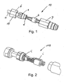
- Fig. 1
- eine perspektivische Ansicht eines ersten Ausführungsbeispiels eines EMV-Steckverbinders;
- Fig. 2
- ein zweites Ausführungsbeispiel eines EMV-Steckverbinders;
- Fig. 3-4
- Einzelheiten des ersten Ausführungsbeispiels; und
- Fig. 5-6
- Einzelheiten des zweiten Ausführungsbeispiels.
- Fig. 1
- a perspective view of a first embodiment of an EMC connector;
- Fig. 2
- a second embodiment of an EMC connector;
- Fig. 3-4
- Details of the first embodiment; and
- Fig. 5-6
- Details of the second embodiment.
Diese beiden in
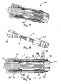
- Fig. 7
- eine schematische Schnittansicht des ersten Ausführungsbeispiels;
- Fig. 8
- eine noch nicht montierten Zustand des EMV-Steckverbinders gemäß
Fig. 7 ; - Fig. 9
- eine Schnittansicht des Steckverbinders gemäß
Fig. 7 ; - Fig. 10
- eine Schnittansicht des Steckverbinders des zweiten Ausführungsbeispiels;
- Fig. 11
- eine auseinandergezogene Ansicht des EMV-Steckverbinders der
Fig. 10 ; - Fig. 12
- eine Einzelheit der Schirmübergabe;
- Fig. 13
- eine Schnittansicht des EMV-Steckverbinders gemäß
Fig. 10 ; - Fig. 14
- eine Einzelheit des ersten Ausführungsbeispiels und
- Fig. 15
- eine Einzelheit des zweiten Ausführungsbeispiels.
- Fig. 7
- a schematic sectional view of the first embodiment;
- Fig. 8
- an unassembled state of the EMC connector according to
Fig. 7 ; - Fig. 9
- a sectional view of the connector according to
Fig. 7 ; - Fig. 10
- a sectional view of the connector of the second embodiment;
- Fig. 11
- an exploded view of the EMC connector of
Fig. 10 ; - Fig. 12
- a detail of the screen transfer;
- Fig. 13
- a sectional view of the EMC connector according to
Fig. 10 ; - Fig. 14
- a detail of the first embodiment and
- Fig. 15
- a detail of the second embodiment.
Beschreibung der beiden Ausführungsbeispiele der Erfindung unter Bezugnahme auf die
In der Zeichnung ist mit a eine geschirmte Leitung bezeichnet und b bezieht sich auf gekrimmpte Kontakte. Das Schirmgeflecht oder der Kabelschirm ist mit c bezeichnet, und eine konische Scheibe allgemein ein Trägerelement ist bei d gezeigt. Ferner ist f eine Mutter und g ist eine Steckerhülse. Weiterhin ist h ein Kunststoffelement zur Aufnahme der getrimmten Kontakte und e ist eine Krimpumhüllung. Ein Hülsenkörper g wird auch als Position 6 bezeichnet.In the drawing, a denotes a shielded line and b refers to a crimped contacts. The screen braid or the cable shield is labeled c, and a conical disk generally a support member is shown at d. Further, f is a nut and g is a plug sleeve. Furthermore, h is a plastic element for receiving the trimmed contacts, and e is a crimping cladding. A sleeve body g is also referred to as position 6.
Der Zusammenbau des Steckverbinders gemäß den
- 1. Die Positionen 1 + 2, d.h. Halteschraube f + s Krimpumhüllung e werden auf das Kabel a geschoben.
- 2. Das Kabel a wird wie in der Zeichnung dargestellt teilweise vom Geflecht c freigelegt.
- 3.
Die Position 3, d.h. ein Trägerelement, eine konische Scheibe d wird auf das Kabel a aufgesetzt. - 4. Die Kontakte b werden gekrimpt.
- 5. Die Kontakte b werden in Position 5, d.h. das Kunststoffelement h eingeschnappt, wobei Vorsorge getroffen ist, das die Kontakte b richtig eingeschnappt werden.
- 6. Die Position 4, d.h. eine Krimphülse i wird auf dem gezeigten Platz auf dem Kabel a angeordnet und umgelegt und die Positionen 2 - 5, d.h. die Krimpumhüllung bzw. Geflechtverbindungselement e, die konische Scheibe d, die Krimphülse i und der Hülsenkörper g werden zusammengeschoben.
- 7. Es wird dafür Vorsorge getragen, dass die Abschirmung c zwischen den Positionen 2 und 3 d.h. dem Schirmelement e und der konischen Scheibe d zusammengepresst wird und die Abschirmung c wird abgeschnitten, so sie dass nicht den O Ring überlappend gelassen wird.
- 8. Alle Bauteile werden in die Position 6, d.h. den Hülsenkörper (Steckerhülse) g eingesetzt, wobei die Codierung in der richtigen Position erfolgt und die Befestigung mit der Stecker- bzw. Halteschraube Position 1 beziehungsweise f durchgeführt wird.
- 1. The positions 1 + 2, ie retaining screw f + s Krimpumhüllung e are pushed onto the cable a.
- 2. The cable a is partially exposed from the braid c as shown in the drawing.
- 3. The
position 3, ie a support member, a conical disc d is placed on the cable a. - 4. The contacts b are crimped.
- 5. The contacts b are in position 5, that is, the plastic element h snapped, taking precautions that the contacts b are snapped properly.
- 6. The position 4, ie a crimping sleeve i is placed and folded on the shown space on the cable a and the positions 2-5, ie the crimping or braid connection element e, the conical disc d, the crimping sleeve i and the sleeve body g pushed together.
- 7. It is ensured that the shield c is compressed between the
positions 2 and 3, that is, the shield member e and the conical disk d, and the shield c is cut so as not to overlap the O ring. - 8. All components are in the position 6, ie the sleeve body (plug sleeve) g used, the coding is done in the correct position and the attachment with the plug or retaining screw position 1 or f is performed.
Zusammenfassend sieht die Erfindung Folgendes vor:
- 1. Ein EMV-Steckverbinder ist mit 360° Schirmanbindung ausgebildet, wobei mit einem Steckergehäuse der Kabelschirm bzw. das Schirmgeflecht einer geschirmten Leitung vollflächig verbunden ist. Der Steckverbinder nach 1, wobei ein leitendes Bauelement lückenlos und vollflächig den Kabelschirm an das Steckergehäuse übergibt. Der Steckverbinder nach 1 und 2, wobei durch ein speziell geformtes Trägerelement beispielsweise eine konische Scheibe das Schirmgeflecht einer geschirmten Leitung z.B. durch ein Kunststoffelement beispielsweise Kunststoffelement geklemmt wird. Der Steckverbinder nach einem der vorherigen Punkte, wobei das Steckergehäuse einen Bund aufweist, auf den das Trägerelement die Schirmung presst, und so die Schirmung an das Gehäuse übergibt. Der Steckverbinder nach einem der vorgehenden Punkte, wobei das Kunststoffelement an seiner Außenseite eine Form hat, die verhindert, dass das überstehende Schirmgeflecht die Montage und Funktion des Steckverbinders beeinträchtigt.
- 1. An EMC connector is designed with 360 ° shield connection, wherein the cable shield or the shield braid of a shielded cable is connected over the entire surface with a connector housing. The connector according to FIG. 1, wherein a conductive component completely and completely transfers the cable screen to the connector housing. The connector according to FIGS. 1 and 2, wherein the shield braid of a shielded line is clamped by a specially shaped carrier element, for example a conical disk, for example by a plastic element, for example a plastic element. The connector of any preceding item, wherein the connector housing has a collar on which the support member presses the shield, thus passing the shield to the housing. The connector according to any preceding item, wherein the plastic member has on its outside a shape that prevents the protruding braid affects the assembly and function of the connector.
Beschreibung der beiden Ausführungsbeispiele der Erfindung anhand der
- A)
Figuren 7 undbis 915 zeigen ein erstes Ausführungsbeispiel.Figur 7 ist ein Längsschnitt eines Steckverbinders (Rundsteckverbinder) 10, insbesondere eines EMV-Steckverbinders 10.Der Steckverbinder 10 weist ein einen Innenraum umschließendes, hülsenförmiges Gehäuse 11 auf, welches kabelseitig eine Kabeleintrittsöffnung 63 und steckseitig eine Stecköffnung 62 (Fig. 9 ) besitzt. Am Außenumfang des Gehäuses 11 iststeckseitig eine Rändelschraube 53 drehbar (aber nur beschränkt axial verschiebbar) gelagert, um mit einem nicht gezeigten Gegensteckverbinder oder einer Buchse verschraubt zu werden.
Benachbart zur Kabeleintrittsöffnung 63 des Gehäuses 11 ist auf dieses eine Kabelverschraubung 15 aufgeschraubt.
Das Gehäuse 11
Im Innenraum des Gehäuses 11 ist in einem Bereich A nahe der Stecköffnung 62 desGehäuses 11 ein Isolierkörper 12 eingesetzt, der Kontaktelemente 51 trägt. Nach Innen gegenüber der Kabeleintrittsöffnung 63 ist in einem Bereich C des Gehäuses 11ein Klemmkäfig 13 eingesetzt, der in Axialrichtung ein Stück verschiebbar ist, der aber vorzugsweise nicht verdrehbar ist. In dem ersten Ausführungsbeispielist der Klemmkäfig 13 zweiteilig und besitzt einen Hauptteil 13a und einen rohrförmigen Einsatzteil 13b. Innerhalb des Hauptteils 13a ist der unmittelbar auf einemKabel 13sitzende Einsatzrohrteil 13b angeordnet, der vorzugsweise Finger 99 (vgl.Fig. 4 ) aufweist.
Der Abstandzwischen dem Isolierkörper 12und dem Klemmkäfig 13 wird durch ein ein steckseitiges und ein kabelseitiges Ende aufweisendes Distanzelement 16 überbrückt. Das Distanzelement 16 stützt sich mit seinem steckseitigen Ende amIsolierkörper 12 ab und mit seinem kabelseitigen Ende an einer Schirmübergabe 14 (imFolgenden kurz Kontaktscheibe 14 genannt).
Die im Innenraum des Gehäuses 11angeordnete Kontaktscheibe 14 stellt einen elektrischen Kontakt zwischendem Gehäuse 11 und einem Kabelschirm 18 her.Der Kabelschirm 18 umhüllt das gesamte abgeschirmteKabel 17.Über dem Kabelschirm 18, dort wodas Kabel 17 nicht abisoliert ist, verläuft eine Kabelisolierschicht desKabels 17. Diese ist im Bereich der Schirmübergabe 14 entfernt.
Das Gehäuse 11 bildet an seiner Innenwand steckseitig eine vorzugsweise kreisringförmige Anschlagfläche 23 für eine daran anliegende, ebenfalls vorzugsweise kreisringförmige Anschlagfläche 24 desIsolierkörpers 12.Das Gehäuse 11 bildet ferner an seiner Innenoberfläche benachbart zum steckseitigen Ende desKlemmkäfigs 13eine Auflagefläche 36 für einen Ringscheibenabschnitt 80der Kontaktscheibe 14.
Der Innenraum des Gehäuses 11 ist, bedingt durch die Anschlagfläche 23 und dieAuflagefläche 36 abgestuft, d.h. der Innendurchmesser des Innenraums ist beginnend ander Stecköffnung 62 und endend an der Anschlagfläche 23 am kleinsten, ist etwas größer zwischen der Anschlagfläche 23 und der Auflagefläche 36 und ist daran anschließend am größtenvon der Auflagefläche 36 bis zur der Kabeleintrittsöffnung 63 des Gehäuses.
Der Isolierkörper 12
Der Isolierkörper 12 hat Öffnungen zur Aufnahme der Kontaktelemente 51. Der Außenumfang des Isolierkörpers 12 ist am größten anschließend an eine steckseitig vorgesehene Anschlagfläche 24 und bildet so einen Anlageabschnitt 26 zur Anlage mit seinem Außenumfang an einem entsprechenden Abschnitt des Innenumfangs desGehäuses 11. Anschließend anden Anlageabschnitt 26 ist der Außendurchmesser des Isolierkörpers 12 verkleinert, um eine ringförmige Ausnehmung 27 zu bilden, die sich von einer ringförmigen Anschlagfläche 28 desIsolierkörpers 12 über die restliche Länge des Isolierkörpers 12 hinweg erstreckt.
Das Distanzelement 16
Das Distanzelement 16 besteht vorzugsweise aus Kunststoff und ist in der Form eines Rohres ausgebildet, wobei das Rohr an einer Stelle durch einen Längsschlitz durchtrennt wird, so dass sich zwei schalenförmige das Rohr bildende Teile ergeben, die bezüglich einander aufgeklappt werden können und die in zusammengeklapptem Zustand in der inFigur 1 gezeigten Art und Weise einen Abschnitt D desIsolierkörpers 12 umhüllend im Innenraum des Gehäuses 11 angeordnet werden können.
Der Isolierkörper 12 hat wie erwähnt eine steckseitige Anschlagfläche 28, die mit einer stirnseitigen Anschlagfläche 29 des Distanzelements 16 zusammenstößt und das Distanzelement 16 dort abstützt, wenn eine Kraft auf das andere, eine weitere (kabelseitig vorgesehene) stirnseitige Anschlagfläche 64 bildende Ende des Distanzelements 16, ausgeübt wird.Die kabelseitige Anschlagfläche 64 des Distanzelements 16 liegt ander Kontaktscheibe 14 an.
Der Klemmkäfig 13
Der Klemmkäfig 13 ist im Bereich C des Gehäuses 11 eingesetzt und ragt ausdem Gehäuse 11 heraus. Im Innenraum des Klemmkäfigs 13verläuft das Kabel 17, welches im Bereich der Schirmübergabe 14 abisoliert ist. Im dargestellten Ausführungsbeispielist der Klemmkäfig 13 wie erwähnt zweiteilig ausgebildet und zwar aus dem in Axialrichtung nach innen gelegenen Hauptteil 13a und dem in Axialrichtung nach außen gelegenen Einsatzrohrteil 13b.Der Einsatzrohrteil 13b sitzt in einer Ausnehmung 70 desHauptteils 13a und erstreckt sich von dort aus zu einer Kabeleintrittsöffnung 32, dievon der Kabelverschraubung 15 gebildet wird.Der Klemmkäfig 13bildet eine Anschlagfläche 71 zur Zusammenarbeitmit der Kabelverschraubung 15. Im dargestellten Ausführungsbeispielist der Hauptteil 13a rohrförmig und bildet an dem entgegengesetzt zur Anschlagfläche 71 liegenden Ende eine Kabelschirmauflagefläche 96, die vorzugsweise abgerundet ist und in Axialrichtung weist. Zu dem Innenraum des Klemmkäfigs 13 hin ist die Kabelschirmauflagefläche 96 über eine Schrägfläche verbunden. Am Außenumfang des Klemmkäfigs 13 ist, benachbart und ausgehend von der Kabelschirmauflagefläche 96, eine ringförmige Ausnehmung 73 gebildet, die von einem ringförmigen Vorsprung 74 begrenzt wird, an welchen anschließend eine Ausnehmung 75 zur Aufnahme einer Dichtung 50 gebildet wird. Anschließend an die Ausnehmung 75 ist der Durchmesser des Klemmkäfigs 13 gleich dem Außendurchmesser des Vorsprungs 74 und zwar zur Anlage an der Innenoberfläche des Gehäuses 11 in einem Teil des AbschnittsC. Der Klemmkäfig 13 ist an seinem kabelseitigen Ende ferner mit einem in eine Ausnehmung des Gehäuses 11eingreifenden Vorsprung 77 versehen, um eine Verdrehung des Klemmkäfigs 13 zu verhindern.
Die Schirmübergabe 14
Die Schirmübergabe 14 ist vorzugsweise, wie bereits erwähnt, in der Form einerKontaktscheibe 14 ausgebildet. DieseKontaktscheibe 14 besitzt einenRingscheibenabschnitt 80, der im Wesentlichen radial zur Steckerlängsachse nach außen hin verläuft. Anden Ringscheibenabschnitt 80 anschließend ist ein in den Innenraum des Klemmkäfigs 13verlaufender Ringkonusabschnitt 81 ausgebildet, der anschließend anden Ringscheibenabschnitt 80einen Krümmungsteil 82 und daran anschließend einen geraden Teil 83 umfasst.
BeimZusammenbau des Steckverbinders 10 werden die Kontakte 51 inden Isolierkörper 12 gesteckt, und das Distanzelement 16 wird aufden Isolierkörper 12 aufgesetzt. Wenn das Distanzelement 16 aus zwei miteinander verbundenen Halbschalen besteht, so werden die beiden Halbschalen zur Bildung einer Umhüllung fürden Isolierkörper 12 und die Kabelenden zusammengelegt und können dann ins Gehäuse 11 eingeschoben werden,wobei die Schirmübergabe 14 zusammenmit dem Klemmkäfig 13 ebenfalls ins Gehäuse 11 eingeschoben wird. Zuvor wird der Kabelschirm 18 um die Kabelschirmauflagefläche 96, wie inder Figur 14 gezeigt, herumgelegt, so dassdas freie Ende 85 des Kabelschirms 18 in der Ausnehmung 73 liegt.Der Kabelschirm 18 ist dabei insbesondere im Bereich der Kabelschirmauflagefläche 96 in gutem Kontakt mit der zur Kabeleintrittsöffnung hinweisenden Andruckfläche 86 desRingscheibenabschnitts 80.
Abschließend wirddann die Kabelverschraubung 15 auf ein im Außenumfang im Bereich der aufzuschraubenden Kabelverschraubung vorgesehenes Gewinde des Gehäuses 11 aufgeschraubt, wobei eine Steuer- oder Anlagefläche, im dargestellten Ausführungsbeispiel eine Schrägfläche 72, gegen das zur Kabeleintrittsöffnung 32 hinweisende Ende desKlemmkäfigs 13 drückt und dieSchirmübergabe 14 mit guter Kontaktgabe zum Gehäuse 11 drückt, wobei das Distanzelement 16 auchmit seiner Anschlagfläche 64 ander Schirmübergabe 14 vorzugsweise im Bereich der Kabelschirmauflagefläche 96 anliegt. - B)
Figuren 10bis 1315 betreffen das zweite Ausführungsbeispiel und zeigen mitAusnahme von Figur 11 Längsschnitte eines Rundsteckverbinders 110 insbesondere eines EMV-Steckverbinders gemäß dem zweiten Ausführungsbeispiel.Fig. 11 zeigt den Steckverbinder 110 in einer perspektivischen Ansicht.Der Steckverbinder 110 weist ein einen Innenraum umschließendes, hülsenförmiges Gehäuse 111 auf, welches kabelseitig eine Kabeleintrittsöffnung 163 und steckseitig eine Stecköffnung 162 besitzt. AmAußenumfang des Gehäuses 111 iststeckseitig eine Rändelschraube 153 drehbar gelagert, um mit einem nicht gezeigten Gegensteckverbinder oder einer Buchse verschraubt zu werden.
Benachbart zur Kabeleintrittsöffnung 163 desGehäuses 111 ist auf dieses eine Kabelverschraubung 115 aufgeschraubt.
Das Gehäuse 111
ImInnenraum des Gehäuses 111 ist in einem Bereich A (vgl.Fig. 13 ) nahe derStecköffnung 162 desGehäuses 111 ein Isolierkörper 112 eingesetzt, der Kontaktelemente trägt. Nach Innen gegenüber derKabeleintrittsöffnung 163 ist in einem Bereich C desGehäuses 111 ein Klemmkäfig 113 eingesetzt, der in Axialrichtung ein Stück verschiebbar ist, der aber vorzugsweise nicht verdrehbar ist. In dem inFigur 15ist der Klemmkäfig 113 ebenfalls zweiteilig und besitzt einen Hauptteil 113a und einen rohrförmigen Einsatzteil 113b. Innerhalb des Hauptteils 113a ist der unmittelbar auf einemKabel 113 sitzende Einsatzrohrteil 113b angeordnet, der vorzugsweise Finger 199 (vgl.Figur 6 ) aufweist.
Der Abstandzwischen dem Isolierkörper 112und dem Klemmkäfig 113 wird im Wesentlichendurch ein Distanzelement 116 überbrückt. Letzteres weist ein eine steckseitige, stirnseitige Anschlagfläche 129 bildendes Ende auf.Das Distanzelement 116 stützt sich mit seinem steckseitigen Ende insbesondere der Anschlagfläche 129 ander Anschlagfläche 128 desIsolierkörpers 112 ab. Mit seinem kabelseitigen Ende stützt sichdas Distanzelement 116 an einer Schirmübergabe 114 (imFolgenden kurz Kontaktscheibe 114 genannt) ab.
Die im Innenraum desGehäuses 111 angeordnete Kontaktscheibe 114 stellt einen elektrischen Kontakt zwischendem Gehäuse 111 und einem Kabelschirm 118 her.Der Kabelschirm 118 umhüllt das gesamte abgeschirmte Kabel 117.Über dem Kabelschirm 118, dort wo das Kabel nicht abisoliert ist, verläuft eine Kabelisolierschicht. Diese ist imBereich der Schirmübergabe 114 entfernt.
Im Einzelnenbildet das Gehäuse 111 an seiner Innenwand steckseitig eine vorzugsweise kreisringförmige Anschlagfläche 123 für eine daran anliegende, ebenfalls vorzugsweise kreisringförmige Anschlagfläche 124 desIsolierkörpers 112.Das Gehäuse 111 bildet ferner an seinerInnenoberfläche eine Auflagefläche 136 für dieKontaktscheibe 114 insbesondere für einenRingscheibenabschnitt 180der Kontaktscheibe 114.
Der Innenraum desGehäuses 111 ist, bedingt durch dieAnschlagfläche 123 und dieAuflagefläche 136 abgestuft, d.h. der Innendurchmesser des Innenraums ist beginnend benachbart zu einerStecköffnung 162 und endend ander Anschlagfläche 123 am kleinsten, ist etwas größer zwischen derAnschlagfläche 123 und derAuflagefläche 136 und ist daran anschließend am größtenvon der Auflagefläche 136bis zur Kabeleintrittsöffnung 163 desGehäuses 111, und bildet sozusagen eine Ausnehmung 195 an deren Innenfläche derKlemmkäfig 113 axial verschiebbar anliegt.
Der Isolierkörper 112
Der Isolierkörper 112 hat Öffnungen zur Aufnahme derKontakte 151. Der Außenumfang desIsolierkörpers 112 ist am größten anschließend an seine steckseitig vorgesehene Anschlagfläche 124 und bildet so einen Anlageabschnitt 126 zur Anlage mit seinem Außenumfang an einem entsprechenden Abschnitt des Innenumfangs desGehäuses 111. Anschließend an den Anlageabschnitt 126 ist der Außendurchmesser desIsolierkörpers 112 verkleinert, um eine ringförmige Ausnehmung 127 zu bilden, die sich von einer ringförmigen Anschlagfläche 128 über die restliche Länge desIsolierkörpers 112 hinweg erstreckt.
Das Distanzelement 116
Das Distanzelement 116 besteht vorzugsweise aus Kunststoff und ist in der Form eines Rohres ausgebildet, wobei das Rohr an einer Stelle durch einen Längsschlitz durchtrennt wird, so dass sich zwei schalenförmige das Rohr bildende Teile ergeben, die bezüglich einander aufgeklappt werden können und die in zusammengeklapptem Zustand in der inFigur 1 gezeigten Art undWeise den Isolierkörper 112 und dieAdern 152 umhüllen.
Das Distanzelement 116 weist bei diesem zweiten Ausführungsbeispiel zwei, unterschiedliche Innendurchmesser aufweisende, Rohrteile auf. Der eine Rohrteil der imWesentlichen den Isolierkörper 112 umschließt und ein Rohrteil der die Kabeladern und den Bereich des Kabels umschließt, wo die Kabelabschirmung bzw.der Kabelschirm 118 aus dem Kabel herausgeführt ist.Das Distanzelement 116 besitzt an seinem kabelseitigen Ende eineSchirmaufnahme 194die einen Kontaktscheibenaufnahmeraum 200 bildet und zwar zur Aufnahme eines Teils derKontaktscheibe 114 und eines Teils derKabelabschirmung 118.Der Aufnahmeraum 200 und wird von einem nach innen verlaufenden Ringvorsprung 193 begrenzt, wobei in Richtung zur Steckseiteein weiterer Vorsprung 192 vorgesehen ist.Die beiden Ringvorsprünge 192, 193 liegen am abisolierten Außenumfang des Kabels und stützen sodas Distanzelement 116.Die Abschirmung 118 tritt aus dem Kabel heraus inden Aufnahmeraum 200 und ist über dieKontaktscheibe 114 herumgelegt und endet außerhalb desAufnahmeraums 200 wie inder Figur 15 gezeigt.
Der Isolierkörper 112 hateine steckseitige Anschlagfläche 128, die mit einer stirnseitigen Anschlagfläche 129 desDistanzelements 116 zusammenstößt unddas Distanzelement 116 dort abstützt, wenn eine Kraft auf das andere, stirnseitige Ende desDistanzelements 116, ausgeübt wird.
Der Klemmkäfig 113
Der Klemmkäfig 113 ist im Bereich C (vgl.Fig. 9 ) desGehäuses 111 eingesetzt und ragt ausdem Gehäuse 111 heraus. ImInnenraum des Klemmkäfigs 113 verläuft das Kabel 117, welches imBereich der Schirmübergabe 114 abisoliert ist. Im dargestellten Ausführungsbeispielist der Klemmkäfig 113 zweiteilig ausgebildet und zwar aus einem in Axialrichtung nach innen gelegenen Hauptteil 113a und einen in Axialrichtung nach außen gelegenen Einsatzteil 113b.Der Einsatzteil 113b sitzt in einer Ausnehmung 170 des Hauptteils 113a und erstreckt sich von dort aus zu einerKabeleintrittsöffnung 132, dievon der Kabelverschraubung 115 gebildet wird.Der Klemmkäfig 113bildet eine Anschlagfläche 171 zur Zusammenarbeitmit der Kabelverschraubung 115. Im dargestellten Ausführungsbeispiel ist der Hauptteil 113a rohrförmig und bildet an seinem entgegengesetzt zur Anschlagfläche 171 liegendenEnde eine Kabelschirmauflagefläche 196, die vorzugsweise abgerundet ist und in Axialrichtung weist.
Der Klemmkäfig 113 ist ringförmig ausgebildet und liegt mit seiner zylindrischen Außenoberfläche axial beweglich an der Innenoberfläche einer durchdas Gehäuse 111 gebildeten Ausnehmung 195 an.
Eine Ausnehmung 175 zur Aufnahme einerDichtung 150 ist an der Außenoberfläche gebildet. Der Außendurchmesser desKlemmkäfigs 113 ist in etwa gleich dem Innendurchmesser desGehäuses 111 und zwar zur Anlage an der Innenoberfläche desGehäuses 111 imBereich der Ausnehmung 175.
Die Schirmübergabe 114
Die Schirmübergabe 114 ist vorzugsweise, wie bereits erwähnt, in der Form einerKontaktscheibe 114 ausgebildet. DieseKontaktscheibe 114 besitzt einenRingscheibenabschnitt 180, der im Wesentlichen radial zur Steckerlängsachse nach außen hin verläuft. Anden Ringscheibenabschnitt 180 ist anschließend ein inden Aufnahmeraum 200 desDistanzelements 116 verlaufender Ringkonusabschnitt 181 ausgebildet, anschließend anden Ringscheibenabschnitt 180einen Krümmungsteil 182 anschließend daran einen geraden Teil 183 aufweist.
Anders als beim ersten Ausführungsbeispiel taucht derRingkonusabschnitt 182 mit dem,vom Krümmungsteil 182 ausgehenden imWesentlichen geraden Teil 183 ein inden Aufnahmeraum 200der Scheibenaufnahme 194 ein, in den auch dieKabelabschirmung 118 eintritt die um das freie Ende desTeils 183 herum verläuft um dannaus dem Aufnahmeraum 200 auszutreten und die Innenwölbung desKrümmungsteils 182 zu kontaktieren.Die Kabelabschirmung 118 ist dabei in Kontaktmit der Kontaktscheibe 114.Mit seinem Ringscheibenabschnitt 180 ist dieSchirmübergabe 114 in gutem Kontakt direktmit der Auflagefläche 136.
BeimZusammenbau des Steckverbinders 111 werden die Kontakte inden Isolierkörper 112 gesteckt, und das Distanzelement wird aufden Isolierkörper 112 aufgesetzt.Wenn das Distanzelement 116 aus zwei miteinander verbundenen Halbschalen besteht, so werden die beiden Halbschalen zur Bildung einer Umhüllung fürden Isolierkörper 112 und die Kabelenden zusammengelegt und könnendann ins Gehäuse 111 eingeschoben werden,wobei die Schirmübergabe 114 zusammenmit dem Klemmkäfig 113 ebenfalls ins Gehäuse 111 eingeschoben wird. Zuvor wird derKabelschirm 118 um dieKabelschirmauflagefläche 136, wie inder Figur 15 gezeigt, herumgelegt, so dass das freie Ende desKabelschirms 118 großflächig dieSchirmübergabe 114 kontaktiert.Der Kabelschirm 118 ist dabei insbesondere imBereich der Kabelschirmauflagefläche 136 in guten Kontakt mit der zur Kabeleintrittsöffnung hinweisenden Fläche 182 desRingscheibenabschnitts 180.
Abschließend wirddann die Kabelverschraubung 115 auf ein am Außenumfang im Bereich der aufzuschraubenden Kabelverschraubung vorgesehenes Gewinde desGehäuses 111 aufgeschraubt, wobei eine Steuer-oder Anlagefläche 143 gegendas zur Kabeleintrittsöffnung 132 hinweisende Ende desKlemmkäfigs 113 drückt und dieSchirmübergabe 114 mit guter Kontaktgabe zum Gehäuse drückt,wobei das Distanzelement 116 auch mit seiner Anschlagfläche 164 ander Schirmübergabe 114 anliegt.
Das Gehäuse
Auf folgende vorteilhafte Merkmale sei insbesondere hingewiesen:- Im Innenraum des Gehäuses ist ein Isolierkörper an einer Anschlagsfläche des Gehäuses anliegend angeordnet. Das Distanzelement stützt sich mit einer stirnseitigen, steckseitigen Anschlagfläche an einer Anschlagfläche des Isolierkörpers ab. Das Gehäuse bildet an seiner Innenfläche benachbart zum Klemmkäfig 13 eine Anlagefläche für die Kontaktscheibe. Der Innenraum des Gehäuses 11 ist durch die Anschlag- und Auflageflächen abgestuft.
- Der Aussenumfang des Isolierkörpers ist anschließend an seine steckseitig vorgesehene Anschlagfläche am größten und bildet einen Anlageabschnitt zur Anlage am Innenumfang des Gehäuses.
- Das Distanzelement besteht aus Kunststoff und ist rohrförmig ausgebildet. Der Klemmkäfig besitzt steckseitig und axialer Richtung weisend eine Auflagefläche und zwar zur Auflage entweder auf dem Kabelschirm oder auf der Metallscheibe.
- Der Klemmkäfig bildet eine Anschlagfläche zur Zusammenarbeit mit der Kabelverschraubung.
Der Klemmkäfig ist axial verschiebbar aber nicht drehbar im Gehäuse gelagert. - Die Schirmübergabe ist in der Form einer Kontaktscheibe ausgebildet, die einen Ringscheibenabschnitt aufweist, von dem aus ein nach innen verlaufender Ringabschnitt vorgesehen ist.
- A)
FIGS. 7 to 9 and15 show a first embodiment.FIG. 7 is a longitudinal section of a connector (circular connector) 10, in particular anEMC connector 10. Theconnector 10 has an interior enclosing, sleeve-shapedhousing 11, which cable side, a cable inlet opening 63 and plug side, a plug-in opening 62 (FIG.Fig. 9 ) owns. On the outer circumference of thehousing 11, aknurled screw 53 is rotatably mounted on the plug side (but only limited axially displaceable) in order to be screwed to a mating plug connector or a socket (not shown).
Adjacent to the cable entry opening 63 of thehousing 11 is screwed onto this acable gland 15.
Thehousing 11
In the interior of thehousing 11, an insulatingbody 12 is used in a region A near theinsertion opening 62 of thehousing 11, the contact elements 51 carries. Inwardly opposite the cable entry opening 63, a clampingcage 13 is inserted in a region C of thehousing 11, which is displaceable in the axial direction a piece, but which is preferably not rotatable. In the first embodiment, the clampingcage 13 is in two parts and has amain part 13a and atubular insert part 13b. Within themain part 13a of the directly seated on acable 13insert tube part 13b is arranged, preferably fingers 99 (see.Fig. 4 ) having.
The distance between the insulatingbody 12 and the clampingcage 13 is a plug-side and a cable-side end having bridging spacer element 16. The spacer element 16 is supported with its plug-side end on the insulatingbody 12 and with its cable-side end to a screen transfer 14 (hereinafter referred to briefly contact disk 14).
The arranged in the interior of thehousing 11contact disc 14 makes electrical contact between thehousing 11 and acable shield 18 ago. Thecable shield 18 encloses the entire shieldedcable 17. About thecable shield 18, where thecable 17 is not stripped, runs a Kabelinsierschicht thecable 17. This is in the shieldingarea 14 away.
Thehousing 11 forms on its inner wall plug side, a preferably annular abutment surface 23 for an adjoining, also preferablyannular abutment surface 24 of the insulatingbody 12. Thehousing 11 further forms on its inner surface adjacent to the plug-side end of the clampingcage 13 has asupport surface 36 for anannular disc portion 80 ofContact disk 14.
The interior of thehousing 11 is due to the stop surface 23 and thesupport surface 36 graded, ie the inner diameter of the interior is starting at theinsertion opening 62 and ending at the stop surface 23 smallest, is slightly larger between the stop surface 23 and thesupport surface 36 and is then the largest of thesupport surface 36 to the cable entry port 63 of the housing.
The insulating body 12th
The insulatingbody 12 has openings for receiving the contact elements 51. The outer circumference of the insulatingbody 12 is the largest subsequent to a plug-side providedstop surface 24 and The outer diameter of the insulatingbody 12 is then reduced to form anannular recess 27 extending from anannular abutment surface 28 of the insulatingbody 12 extends over the remaining length of the insulatingbody 12 away.
The spacer element 16
The spacer element 16 is preferably made of plastic and is formed in the shape of a tube, wherein the tube is severed at one point by a longitudinal slot, so that there are two cup-shaped parts forming the tube, which can be unfolded with respect to each other and in the collapsed state in the inFIG. 1 As shown, a portion D of the insulatingbody 12 can be arranged enveloping in the interior of thehousing 11.
The insulatingbody 12 has, as mentioned, a plug-side abutment surface 28 which collides with an end-face abutment surface 29 of the spacer element 16 and the spacer 16 is supported there, if a force on the other, another (cable side provided) end-side abutment surface 64 forming end of the spacer element 16, is exercised. The cable-side stop surface 64 of the spacer element 16 abuts against thecontact disk 14.
The clampingcage 13
The clampingcage 13 is inserted in the region C of thehousing 11 and projects out of thehousing 11. In the interior of the clampingcage 13, thecable 17, which is stripped in the region of theshield transfer 14 runs. In the illustrated embodiment, the clampingcage 13 as mentioned formed in two parts, namely from the axially inwardmain body 13a and the axially outwardinsert tube part 13b. Theinsert tube part 13b is seated in a recess 70 of themain part 13a and extends from there to acable inlet opening 32, which is formed by thecable gland 15. The clampingcage 13 forms astop surface 71 for cooperation with thecable gland 15. In the illustrated embodiment, themain part 13a is tubular and forms at the opposite end to thestop surface 71 lying a Kabelschirmauflagefläche 96, which is preferably rounded and facing in the axial direction. To the interior of the clampingcage 13 toward the cable shield support surface 96 is connected via an inclined surface. On the outer circumference of the clampingcage 13, adjacent and starting from the Kabelschirmauflagefläche 96, an annular recess 73 is formed, which is bounded by anannular projection 74, to which then a recess 75 for receiving aseal 50 is formed. Subsequent to the recess 75, the diameter of the clampingcage 13 is equal to the outer diameter of theprojection 74 and that for abutment against the inner surface of thehousing 11 in a part of the section C. The clampingcage 13 is further at its cable end with a in a recess of thehousing 11 engagingprojection 77 provided to prevent rotation of the clampingcage 13.
Thescreen transfer 14
Thescreen transfer 14 is preferably, as already mentioned, in the form of acontact disk 14. Thiscontact disk 14 has anannular disk portion 80, which extends substantially radially to the plug longitudinal axis to the outside. Subsequently, anannular cone section 81 extending into the interior of the clampingcage 13 is formed on theannular disk section 80, which subsequently to theannular disk section 80 comprises acurvature part 82 and subsequently astraight part 83.
When assembling theconnector 10, the contacts 51 are inserted into the insulatingbody 12, and the spacer element 16 is placed on the insulatingbody 12. If the spacer element 16 consists of two interconnected half-shells, the two half shells are folded to form a sheath for the insulatingbody 12 and the cable ends and can then be inserted into thehousing 11, wherein thescreen transfer 14 together with the clampingcage 13 also into the housing 11th is inserted. Previously, thecable shield 18 will wrap around the cable shield support surface 96 as in FIGFIG. 14 shown, so that thefree end 85 of thecable shield 18 is located in the recess 73. In this case, thecable shield 18 is in good contact, in particular in the region of the cable shield contact surface 96, with thecontact surface 86 of theannular disk section 80 which points toward the cable entry opening.
Finally, thecable gland 15 is screwed onto a provided in the outer circumference in the screwed cable gland thread of thehousing 11, wherein a control or contact surface, in the illustrated embodiment, an inclined surface 72, against the cable inlet opening 32 facing end of the clampingcage 13 presses and thescreen transfer 14 presses with good contact with thehousing 11, wherein the spacer element 16 preferably abuts with itsstop surface 64 on thescreen transfer 14 in the region of the cable shield contact surface 96. - B)
FIGS. 10 to 13 and15 relate to the second embodiment and show with the exception ofFIG. 11 Longitudinal sections of acircular connector 110, in particular an EMC connector according to the second embodiment.Fig. 11 shows theconnector 110 in a perspective view. Theplug connector 110 has a sleeve-shapedhousing 111 enclosing an inner space, which has a cable entry opening 163 on the cable side and aninsertion opening 162 on the plug side. On the outer circumference of thehousing 111, aknurled screw 153 is rotatably mounted on the plug side in order to be screwed to a mating plug connector or a socket, not shown.
Adjacent to the cable entry opening 163 of thehousing 111 is screwed onto this acable gland 115.
Thehousing 111
In the interior of thehousing 111 is in a range A (see.Fig. 13 ) is inserted near theinsertion opening 162 of thehousing 111, an insulatingbody 112 which carries contact elements. Inwardly opposite thecable entry opening 163, a clampingcage 113 is inserted in a region C of thehousing 111, which is displaceable in the axial direction a piece, but which is preferably not rotatable. In the inFIG. 15 illustrated embodiment, the clampingcage 113 is also in two parts and has amain part 113a and atubular insert part 113b. Within themain part 113a of the directly on acable 113 fittinginsert tube part 113b is arranged, which preferably fingers 199 (see.FIG. 6 ) having.
The distance between the insulatingbody 112 and the clampingcage 113 is bridged substantially by aspacer element 116. The latter has a plug-side end face abutment surface 129 forming end. Thespacer 116 is supported by his plug-side end, in particular the stop surface 129 on thestop surface 128 of the insulatingbody 112 from. With its cable-side end, thespacer element 116 is supported on a screen transfer 114 (referred to below as thecontact disk 114 for short).
Thecontact disk 114 arranged in the interior of thehousing 111 establishes electrical contact between thehousing 111 and acable shield 118. Thecable shield 118 covers the entire shielded cable 117. Above thecable shield 118, where the cable is not stripped, there is a cable insulation layer. This is located in the area of thescreen transfer 114.
In detail, thehousing 111 on its inner wall plug-side forms a preferablyannular abutment surface 123 for an abutting, also preferablyannular abutment surface 124 of theinsulator 112. Thehousing 111 also forms on its inner surface a bearingsurface 136 for thecontact disc 114 in particular for anannular disc portion 180 ofContact disk 114.
The interior of thehousing 111 is, due to thestop surface 123 and thesupport surface 136 graded, ie the inner diameter of the interior is beginning adjacent to a plug-inopening 162 and ending at thestop surface 123 smallest, is slightly larger between thestop surface 123 and the support surface 136th and is then the largest of the bearingsurface 136 to the cable entry opening 163 of thehousing 111, and thus forms, so to speak, arecess 195 on the inner surface of the clampingcage 113 is axially displaceable.
The insulatingbody 112
The insulatingbody 112 has openings for receiving thecontacts 151. The outer circumference of the insulatingbody 112 is most adjacent to its insertion side providedstop surface 124 and thus forms a contact portion 126 for engagement with its outer periphery at a corresponding portion of the inner circumference of thehousing 111. Subsequently to the Anlageabschnitt 126, the outer diameter of the insulatingbody 112 is reduced to form an annular recess 127 which extends from anannular stop surface 128 over the remaining length of the insulatingbody 112 away.
Thespacer element 116
Thespacer element 116 is preferably made of plastic and is formed in the shape of a tube, wherein the tube is severed at one point by a longitudinal slot, so that there are two cup-shaped parts forming the tube, which can be unfolded with respect to each other and in the collapsed state in the inFIG. 1 shown manner the insulatingbody 112 and thewires 152 envelop.
Thespacer element 116 has, in this second embodiment, two, different inner diameter having, pipe parts. The one tube part which essentially encloses the insulatingbody 112 and a tube part which encloses the cable cores and the region of the cable where the cable shield or thecable shield 118 is led out of the cable. Thespacer element 116 has at its cable-side end of ascreen receptacle 194 which forms a contactdisc receiving space 200 for receiving a portion of thecontact disc 114 and a portion of thecable shield 118. The receivingspace 200 and is bounded by an inwardly extending annular projection 193, wherein in the direction of Plug side anotherprojection 192 is provided. The twoannular projections 192, 193 are located on the stripped outer periphery Theshield 118 exits the cable into the receivingspace 200 and is placed over thecontact disc 114 and ends outside of the receivingspace 200 as in theFIG. 15 shown.
The insulatingbody 112 has a plug-side abutment surface 128, which collides with an end-face abutment surface 129 of thespacer element 116 and thespacer element 116 is supported there when a force on the other end face of thespacer element 116, is exercised.
The clampingcage 113
The clampingcage 113 is in the area C (see.Fig. 9 ) of thehousing 111 and protrudes out of thehousing 111. In the interior of the clampingcage 113 runs the cable 117, which is stripped in the region of theshield transfer 114. In the illustrated embodiment, the clampingcage 113 is formed in two parts, namely from an axially inwardly locatedmain portion 113a and an axially outwardly insert 113b. Theinsert part 113b is seated in a recess 170 of themain part 113a and extends from there to a cable inlet opening 132 which is formed by thecable gland 115. The clampingcage 113 forms astop surface 171 for cooperation with thecable gland 115. In the illustrated embodiment, themain part 113a is tubular and forms at its opposite end to thestop surface 171 lyingend Kabelschirmauffläche 196, which is preferably rounded and facing in the axial direction.
The clampingcage 113 is annular and lies with its cylindrical outer surface axially movable on the inner surface of a recess formed by thehousing 111 195 on.
Arecess 175 for receiving aseal 150 is formed on the outer surface. The outer diameter of the clampingcage 113 is approximately equal to the inner diameter of thehousing 111 and that for abutment against the inner surface of thehousing 111 in the region of the recess 175th
Thescreen transfer 114
Thescreen transfer 114 is preferably, as already mentioned, in the form of acontact disk 114. Thiscontact disk 114 has anannular disk portion 180, which extends substantially radially to the plug longitudinal axis to the outside. An annular cone section 181 extending into the receivingspace 200 of thespacer element 116 is then formed on theannular disk section 180, followed by acurved section 182 having astraight section 183 adjacent to theannular disk section 180.
Unlike the first embodiment, theannular cone portion 182, with the substantiallystraight portion 183 extending from thecurvature portion 182, plunges into the receivingspace 200 of thedisc receptacle 194 into which thecable shield 118 enters which extends around the free end of theportion 183 to exit from the receivingspace 200 and to contact the inner curvature of thecurvature part 182. Thecable shield 118 is in contact with thecontact disk 114. With itsannular disk portion 180, thescreen transfer 114 is in good contact directly with the support surface 136th
When assembling theconnector 111, the contacts are inserted into the insulatingbody 112, and the spacer element is placed on the insulatingbody 112. If thespacer 116 consists of two interconnected shells, the two Half shells folded to form a sheath for the insulatingbody 112 and the cable ends and can then be inserted into thehousing 111, wherein thescreen transfer 114 is also inserted into thehousing 111 together with the clampingcage 113. Previously, thecable shield 118 will wrap around the cableshield support surface 136, as in FIGFIG. 15 shown, so that the free end of the cable shield 118 a large area theshield transfer 114 contacted. In this case, thecable shield 118 is in good contact, in particular in the area of the cableshield contact surface 136, with thesurface 182 of theannular disk section 180 which points toward the cable entry opening.
Finally, thecable gland 115 is then screwed onto a thread of thehousing 111 provided on the outer circumference in the region of the cable gland to be screwed, wherein a control orcontact surface 143 presses against the end of the clampingcage 113 facing thecable inlet opening 132 and presses thescreen transfer 114 with good contact with the housing , wherein thespacer element 116 also abuts with its stop surface 164 on thescreen transfer 114.
Thehousing
The following advantageous features should be noted in particular:- In the interior of the housing, an insulating body is arranged adjacent to a stop surface of the housing. The spacer element is supported by an end-side, plug-side abutment surface on a stop surface of the insulating body. The housing forms on its inner surface adjacent to the clamping
cage 13 a contact surface for the contact disc. The interior of thehousing 11 is stepped by the stop and support surfaces. - The outer circumference of the insulating body is then at its insertion side provided stop surface largest and forms a contact portion for abutment on the inner circumference of the housing.
- The spacer element is made of plastic and is tubular. The clamping cage has plug side and axial direction facing a support surface and that to rest either on the cable shield or on the metal disc.
- The clamping cage forms a stop surface for cooperation with the cable gland.
The clamping cage is axially displaceable but not rotatably mounted in the housing. - The shield transfer is in the form of a contact disc having an annular disc portion from which an inwardly extending annular portion is provided.
- In the interior of the housing, an insulating body is arranged adjacent to a stop surface of the housing. The spacer element is supported by an end-side, plug-side abutment surface on a stop surface of the insulating body. The housing forms on its inner surface adjacent to the clamping
- 1010
- Steckverbinder, insbesondere EMV-SteckverbinderConnectors, in particular EMC connectors
- 11.11th
- Gehäusecasing
- 12.12th
- Isolierkörperinsulator
- 13.13th
- Klemmkäfigclamping cage
- 13a.13a.
- HauptteilBulk
- 13b.13b.
- Einsatzteilinsert
- 1414
- Schirmübergabe, KontaktscheibeScreen transfer, contact disc
- 1515
- KabelverschraubungCable gland
- 16.16th
- Distanzelementspacer
- 17.17th
- geschirmtes Kabelshielded cable
- 18.18th
- Kabelschirmcable shield
- 20.20th
- Hülseshell
- 2121
- Außenoberflächeouter surface
- 2222
- Innenoberflächeinner surface
- 2323
- Anschlagfläche des GehäusesStop surface of the housing
- 2424
- Anschlagfläche des IsolierkörpersStop surface of the insulating body
- 2525
- Anschlagflächestop surface
- 2626
- Anlageabschnittcontact section
- 2727
- Ausnehmung des IsolierkörpersRecess of the insulating body
- 2828
- Anschlagfläche des IsolierkörpersStop surface of the insulating body
- 2929
- stirnseitige Anschlagfläche des Distanzelementsend-face stop surface of the spacer element
- 3030
- Innenoberflächeinner surface
- 3131
- Außenoberflächeouter surface
- 3232
- KabeleintrittsöffnungCable inlet opening
- 3333
- KabelaustrittsöffnungCable outlet opening
- 3434
- KabelaufnahmeraumCable accommodating space
- 3535
- stirnseitige Anschlagflächeend stop surface
- 3636
- Kabelschirmauflagefläche des GehäusesCable shield contact surface of the housing
- 3737
- abgerundete Stirnflächerounded end face
- 3838
- außen umlaufende Ringauflageflächeouter circumferential ring bearing surface
- 3939
- innen umlaufende Ringauflageflächeinside circumferential ring contact surface
- 4040
- Ringabschnittring section
- 4141
- Ringnutring groove
- 4242
- Federarmabschnittspring arm
- 4444
- KabeleintrittsöffnungCable inlet opening
- 5050
- Dichtungpoetry
- 5151
- Kontaktelementcontact element
- 5252
- Adernveins
- 5353
- Rändelschraubethumbscrew
- 6060
- Außengewindeexternal thread
- 6161
- Absatzparagraph
- 6262
- Stecköffnungplug-in opening
- 6363
- KabeleintrittsöffnungCable inlet opening
- 6464
- stirnseitige Anschlagfläche des Distanzelementsend-face stop surface of the spacer element
- 7070
-
Ausnehmung des Hauptteils 13aRecess of the
main part 13a - 7171
- Anschlagfläche des KlemmkäfigsStop surface of the clamping cage
- 7272
- Schrägfläche der KabelverschraubungInclined surface of the cable gland
- 7373
- ringförmige Ausnehmung des Klemmkäfigsannular recess of the clamping cage
- 7474
- ringförmiger Vorsprung des Klemmkäfigsannular projection of the clamping cage
- 7575
- Ausnehmung des KlemmkäfigsRecess of the clamping cage
- 7777
- Vorsprung des KlemmkäfigsProjection of the clamping cage
- 8080
- Ringscheibenabschnitt der KontaktscheibeRing disk section of the contact disk
- 8181
- Ringkonusabschnitt der KontaktscheibeRing cone section of the contact disc
- 8282
- Krümmungsteil der KontaktscheibeCurvature part of the contact disc
- 8383
- gerader Teil der Kontaktscheibestraight part of the contact disc
- 8484
- Gewindethread
- 8585
- freies Ende des Kabelschirmsfree end of the cable shield
- 8686
- AndrucklächeAndruckläche
- 9595
- Ausnehmungrecess
- 9696
- KabelschirmauflageflächeCable shield bearing surface
- 9999
- Fingerfinger
- 193193
- Ringvorsprungannular projection
- 194194
- Scheibenaufnahmedisc recording
- 196196
- Ausnehmungrecess
- 200200
- Aufnahmeraumaccommodation space
Zahlreiche der zweiziffrigen Bezugszeichen werden beim zweiten Ausführungsbeispiel unter Addition von Einhundert verwendet.Many of the two-digit reference numerals are used in the second embodiment with the addition of one hundred.
Claims (9)
Applications Claiming Priority (2)
| Application Number | Priority Date | Filing Date | Title |
|---|---|---|---|
| DE102011112871 | 2011-09-08 | ||
| DE201110120211 DE102011120211A1 (en) | 2011-09-08 | 2011-12-05 | EMC connector |
Publications (2)
| Publication Number | Publication Date |
|---|---|
| EP2568541A1 true EP2568541A1 (en) | 2013-03-13 |
| EP2568541B1 EP2568541B1 (en) | 2017-06-28 |
Family
ID=46785199
Family Applications (1)
| Application Number | Title | Priority Date | Filing Date |
|---|---|---|---|
| EP12005648.6A Active EP2568541B1 (en) | 2011-09-08 | 2012-08-02 | EMC connector |
Country Status (2)
| Country | Link |
|---|---|
| EP (1) | EP2568541B1 (en) |
| DE (1) | DE102011120211A1 (en) |
Cited By (4)
| Publication number | Priority date | Publication date | Assignee | Title |
|---|---|---|---|---|
| CN105006682A (en) * | 2015-07-30 | 2015-10-28 | 中航沈飞民用飞机有限责任公司 | Assembly used for connecting shielding cable and tail of connector |
| CN107768927A (en) * | 2017-10-24 | 2018-03-06 | 浩亭(珠海)制造有限公司 | Connection method of the Ethernet short with shielded connector and connector and cable |
| WO2018172427A1 (en) * | 2017-03-22 | 2018-09-27 | Tyco Electronics (Shanghai) Co. Ltd. | Connector |
| WO2020183111A1 (en) * | 2019-03-14 | 2020-09-17 | Safran Electrical & Power | Device for connecting an electric wiring harness to the rear of an electrical connector |
Families Citing this family (1)
| Publication number | Priority date | Publication date | Assignee | Title |
|---|---|---|---|---|
| DE102015122471B4 (en) | 2015-12-21 | 2017-09-07 | Amphenol-Tuchel Electronics Gmbh | Shielded connector assembly |
Citations (5)
| Publication number | Priority date | Publication date | Assignee | Title |
|---|---|---|---|---|
| DE4101175A1 (en) * | 1990-01-29 | 1991-08-01 | Coninvers Elektrotechnische Bauelemente Gmbh | Connecting plug for screened cable - has contact ring which presses against cable screening to improve ground connection |
| DE4404260A1 (en) * | 1994-02-10 | 1995-08-17 | W W Fischer Sa | Electric plug connector |
| DE19727453A1 (en) * | 1997-06-27 | 1999-01-07 | Amp Gmbh | Round plug connector for screened cable |
| DE19751786A1 (en) * | 1997-11-21 | 1999-05-27 | Whitaker Corp | Round plug connector for screened electrical cable |
| EP1271711A1 (en) * | 2001-06-22 | 2003-01-02 | Intercontec Pfeiffer Gmbh | Contact device for the cable shield of electrical connectors |
-
2011
- 2011-12-05 DE DE201110120211 patent/DE102011120211A1/en not_active Ceased
-
2012
- 2012-08-02 EP EP12005648.6A patent/EP2568541B1/en active Active
Patent Citations (5)
| Publication number | Priority date | Publication date | Assignee | Title |
|---|---|---|---|---|
| DE4101175A1 (en) * | 1990-01-29 | 1991-08-01 | Coninvers Elektrotechnische Bauelemente Gmbh | Connecting plug for screened cable - has contact ring which presses against cable screening to improve ground connection |
| DE4404260A1 (en) * | 1994-02-10 | 1995-08-17 | W W Fischer Sa | Electric plug connector |
| DE19727453A1 (en) * | 1997-06-27 | 1999-01-07 | Amp Gmbh | Round plug connector for screened cable |
| DE19751786A1 (en) * | 1997-11-21 | 1999-05-27 | Whitaker Corp | Round plug connector for screened electrical cable |
| EP1271711A1 (en) * | 2001-06-22 | 2003-01-02 | Intercontec Pfeiffer Gmbh | Contact device for the cable shield of electrical connectors |
Cited By (9)
| Publication number | Priority date | Publication date | Assignee | Title |
|---|---|---|---|---|
| CN105006682A (en) * | 2015-07-30 | 2015-10-28 | 中航沈飞民用飞机有限责任公司 | Assembly used for connecting shielding cable and tail of connector |
| WO2018172427A1 (en) * | 2017-03-22 | 2018-09-27 | Tyco Electronics (Shanghai) Co. Ltd. | Connector |
| US10777943B2 (en) | 2017-03-22 | 2020-09-15 | Tyco Electronics (Shanghai) Co. Ltd. | Connector with a conductive shield having a C-shaped ring |
| CN107768927A (en) * | 2017-10-24 | 2018-03-06 | 浩亭(珠海)制造有限公司 | Connection method of the Ethernet short with shielded connector and connector and cable |
| CN107768927B (en) * | 2017-10-24 | 2024-06-11 | 浩亭(珠海)制造有限公司 | Ethernet short type shielded connector and method for connecting connector with cable |
| WO2020183111A1 (en) * | 2019-03-14 | 2020-09-17 | Safran Electrical & Power | Device for connecting an electric wiring harness to the rear of an electrical connector |
| FR3093866A1 (en) * | 2019-03-14 | 2020-09-18 | Safran Electrical & Power | Device for connecting an electrical harness at the rear of an electrical connector |
| CN113574744A (en) * | 2019-03-14 | 2021-10-29 | 赛峰电气与电源公司 | Device for connecting wire bundle to rear part of electric connector |
| US11710925B2 (en) | 2019-03-14 | 2023-07-25 | Safran Electrical & Power | Device for connecting an electric wiring harness to the rear of an electrical connector |
Also Published As
| Publication number | Publication date |
|---|---|
| DE102011120211A1 (en) | 2013-03-14 |
| EP2568541B1 (en) | 2017-06-28 |
Similar Documents
| Publication | Publication Date | Title |
|---|---|---|
| EP1355386B1 (en) | Round plug connector for shielded electrical cables | |
| DE2331610C2 (en) | Cable connector for fully insulated coaxial cables | |
| US8348697B2 (en) | Coaxial cable connector having slotted post member | |
| DE102015004485B4 (en) | Method for producing a connector assembly | |
| DE69701065T2 (en) | Connector for coaxial cable | |
| EP2568541B1 (en) | EMC connector | |
| DE202011103702U1 (en) | Electrical connector with a cable clamp section | |
| DE10146329A1 (en) | Electrical cable plug for mounting on cable for connection to equipment housing or another cable, has angled housing part for conversion of cable plug between straight plug and angled plug | |
| DE102014109040B4 (en) | Cable connection component, cable connection device, cable connection device and mounting method | |
| DE102004018430A1 (en) | Electrical and mechanical connection arrangement | |
| DE10348321B4 (en) | Waterproof connector | |
| EP0886343A2 (en) | Backshell for electrical connector | |
| DE19751786B4 (en) | Circular connector for a shielded cable | |
| DE202011101574U1 (en) | Connectors | |
| DE102011103586A1 (en) | Plug connector for interconnecting shielded cables, has insulating sleeve protecting wires of cable against electrical contact of housing and resting at stop of housing portion, and contact carrier arranged and held within sleeve | |
| DE102022203174B3 (en) | Circular connector and method of making a circular connector | |
| EP1303020B1 (en) | Electrical cabling with strain relief means | |
| EP1538714A1 (en) | Arrangement for a contact element in a circular connector | |
| DE3137262A1 (en) | ELECTRICAL CONNECTOR FOR CABLES CONTAINING A RELIEF ROPE | |
| EP2104959B1 (en) | Cable entry | |
| DE102011100208A1 (en) | Plug connector e.g. circular plug connector, for connecting multi-core cables, has cable conduit fitting comprising pressure cage, nut and seal, where loading piece and pressure cage are integrally connected with one another | |
| DE102022203219B4 (en) | Circular connector | |
| DE3834171A1 (en) | Single-pole plug with a screen connection, of coaxial type | |
| DE102020121776A1 (en) | Line arrangement and adapter between a first line section and a second line section | |
| DE10140687B4 (en) | patching |
Legal Events
| Date | Code | Title | Description |
|---|---|---|---|
| PUAI | Public reference made under article 153(3) epc to a published international application that has entered the european phase |
Free format text: ORIGINAL CODE: 0009012 |
|
| AK | Designated contracting states |
Kind code of ref document: A1 Designated state(s): AL AT BE BG CH CY CZ DE DK EE ES FI FR GB GR HR HU IE IS IT LI LT LU LV MC MK MT NL NO PL PT RO RS SE SI SK SM TR |
|
| AX | Request for extension of the european patent |
Extension state: BA ME |
|
| 17P | Request for examination filed |
Effective date: 20130913 |
|
| RBV | Designated contracting states (corrected) |
Designated state(s): AL AT BE BG CH CY CZ DE DK EE ES FI FR GB GR HR HU IE IS IT LI LT LU LV MC MK MT NL NO PL PT RO RS SE SI SK SM TR |
|
| 17Q | First examination report despatched |
Effective date: 20160217 |
|
| GRAP | Despatch of communication of intention to grant a patent |
Free format text: ORIGINAL CODE: EPIDOSNIGR1 |
|
| INTG | Intention to grant announced |
Effective date: 20170208 |
|
| GRAS | Grant fee paid |
Free format text: ORIGINAL CODE: EPIDOSNIGR3 |
|
| GRAA | (expected) grant |
Free format text: ORIGINAL CODE: 0009210 |
|
| AK | Designated contracting states |
Kind code of ref document: B1 Designated state(s): AL AT BE BG CH CY CZ DE DK EE ES FI FR GB GR HR HU IE IS IT LI LT LU LV MC MK MT NL NO PL PT RO RS SE SI SK SM TR |
|
| REG | Reference to a national code |
Ref country code: GB Ref legal event code: FG4D Free format text: NOT ENGLISH |
|
| RIN1 | Information on inventor provided before grant (corrected) |
Inventor name: CARLE, ERNST MICHAEL Inventor name: HOENNIGE, JENS-TOBIAS MICHAEL |
|
| REG | Reference to a national code |
Ref country code: CH Ref legal event code: EP |
|
| REG | Reference to a national code |
Ref country code: AT Ref legal event code: REF Ref document number: 905609 Country of ref document: AT Kind code of ref document: T Effective date: 20170715 |
|
| REG | Reference to a national code |
Ref country code: IE Ref legal event code: FG4D Free format text: LANGUAGE OF EP DOCUMENT: GERMAN |
|
| REG | Reference to a national code |
Ref country code: DE Ref legal event code: R096 Ref document number: 502012010628 Country of ref document: DE |
|
| REG | Reference to a national code |
Ref country code: FR Ref legal event code: PLFP Year of fee payment: 6 |
|
| PG25 | Lapsed in a contracting state [announced via postgrant information from national office to epo] |
Ref country code: HR Free format text: LAPSE BECAUSE OF FAILURE TO SUBMIT A TRANSLATION OF THE DESCRIPTION OR TO PAY THE FEE WITHIN THE PRESCRIBED TIME-LIMIT Effective date: 20170628 Ref country code: FI Free format text: LAPSE BECAUSE OF FAILURE TO SUBMIT A TRANSLATION OF THE DESCRIPTION OR TO PAY THE FEE WITHIN THE PRESCRIBED TIME-LIMIT Effective date: 20170628 Ref country code: GR Free format text: LAPSE BECAUSE OF FAILURE TO SUBMIT A TRANSLATION OF THE DESCRIPTION OR TO PAY THE FEE WITHIN THE PRESCRIBED TIME-LIMIT Effective date: 20170929 Ref country code: NO Free format text: LAPSE BECAUSE OF FAILURE TO SUBMIT A TRANSLATION OF THE DESCRIPTION OR TO PAY THE FEE WITHIN THE PRESCRIBED TIME-LIMIT Effective date: 20170928 Ref country code: LT Free format text: LAPSE BECAUSE OF FAILURE TO SUBMIT A TRANSLATION OF THE DESCRIPTION OR TO PAY THE FEE WITHIN THE PRESCRIBED TIME-LIMIT Effective date: 20170628 |
|
| REG | Reference to a national code |
Ref country code: NL Ref legal event code: MP Effective date: 20170628 |
|
| REG | Reference to a national code |
Ref country code: LT Ref legal event code: MG4D |
|
| PG25 | Lapsed in a contracting state [announced via postgrant information from national office to epo] |
Ref country code: RS Free format text: LAPSE BECAUSE OF FAILURE TO SUBMIT A TRANSLATION OF THE DESCRIPTION OR TO PAY THE FEE WITHIN THE PRESCRIBED TIME-LIMIT Effective date: 20170628 Ref country code: NL Free format text: LAPSE BECAUSE OF FAILURE TO SUBMIT A TRANSLATION OF THE DESCRIPTION OR TO PAY THE FEE WITHIN THE PRESCRIBED TIME-LIMIT Effective date: 20170628 Ref country code: LV Free format text: LAPSE BECAUSE OF FAILURE TO SUBMIT A TRANSLATION OF THE DESCRIPTION OR TO PAY THE FEE WITHIN THE PRESCRIBED TIME-LIMIT Effective date: 20170628 Ref country code: SE Free format text: LAPSE BECAUSE OF FAILURE TO SUBMIT A TRANSLATION OF THE DESCRIPTION OR TO PAY THE FEE WITHIN THE PRESCRIBED TIME-LIMIT Effective date: 20170628 Ref country code: BG Free format text: LAPSE BECAUSE OF FAILURE TO SUBMIT A TRANSLATION OF THE DESCRIPTION OR TO PAY THE FEE WITHIN THE PRESCRIBED TIME-LIMIT Effective date: 20170928 |
|
| PG25 | Lapsed in a contracting state [announced via postgrant information from national office to epo] |
Ref country code: RO Free format text: LAPSE BECAUSE OF FAILURE TO SUBMIT A TRANSLATION OF THE DESCRIPTION OR TO PAY THE FEE WITHIN THE PRESCRIBED TIME-LIMIT Effective date: 20170628 Ref country code: CZ Free format text: LAPSE BECAUSE OF FAILURE TO SUBMIT A TRANSLATION OF THE DESCRIPTION OR TO PAY THE FEE WITHIN THE PRESCRIBED TIME-LIMIT Effective date: 20170628 Ref country code: EE Free format text: LAPSE BECAUSE OF FAILURE TO SUBMIT A TRANSLATION OF THE DESCRIPTION OR TO PAY THE FEE WITHIN THE PRESCRIBED TIME-LIMIT Effective date: 20170628 Ref country code: SK Free format text: LAPSE BECAUSE OF FAILURE TO SUBMIT A TRANSLATION OF THE DESCRIPTION OR TO PAY THE FEE WITHIN THE PRESCRIBED TIME-LIMIT Effective date: 20170628 |
|
| PG25 | Lapsed in a contracting state [announced via postgrant information from national office to epo] |
Ref country code: ES Free format text: LAPSE BECAUSE OF FAILURE TO SUBMIT A TRANSLATION OF THE DESCRIPTION OR TO PAY THE FEE WITHIN THE PRESCRIBED TIME-LIMIT Effective date: 20170628 Ref country code: IS Free format text: LAPSE BECAUSE OF FAILURE TO SUBMIT A TRANSLATION OF THE DESCRIPTION OR TO PAY THE FEE WITHIN THE PRESCRIBED TIME-LIMIT Effective date: 20171028 Ref country code: IT Free format text: LAPSE BECAUSE OF FAILURE TO SUBMIT A TRANSLATION OF THE DESCRIPTION OR TO PAY THE FEE WITHIN THE PRESCRIBED TIME-LIMIT Effective date: 20170628 Ref country code: SM Free format text: LAPSE BECAUSE OF FAILURE TO SUBMIT A TRANSLATION OF THE DESCRIPTION OR TO PAY THE FEE WITHIN THE PRESCRIBED TIME-LIMIT Effective date: 20170628 Ref country code: PL Free format text: LAPSE BECAUSE OF FAILURE TO SUBMIT A TRANSLATION OF THE DESCRIPTION OR TO PAY THE FEE WITHIN THE PRESCRIBED TIME-LIMIT Effective date: 20170628 |
|
| REG | Reference to a national code |
Ref country code: CH Ref legal event code: PL Ref country code: DE Ref legal event code: R097 Ref document number: 502012010628 Country of ref document: DE |
|
| PG25 | Lapsed in a contracting state [announced via postgrant information from national office to epo] |
Ref country code: MC Free format text: LAPSE BECAUSE OF FAILURE TO SUBMIT A TRANSLATION OF THE DESCRIPTION OR TO PAY THE FEE WITHIN THE PRESCRIBED TIME-LIMIT Effective date: 20170628 |
|
| PG25 | Lapsed in a contracting state [announced via postgrant information from national office to epo] |
Ref country code: DK Free format text: LAPSE BECAUSE OF FAILURE TO SUBMIT A TRANSLATION OF THE DESCRIPTION OR TO PAY THE FEE WITHIN THE PRESCRIBED TIME-LIMIT Effective date: 20170628 Ref country code: LI Free format text: LAPSE BECAUSE OF NON-PAYMENT OF DUE FEES Effective date: 20170831 Ref country code: CH Free format text: LAPSE BECAUSE OF NON-PAYMENT OF DUE FEES Effective date: 20170831 |
|
| PLBE | No opposition filed within time limit |
Free format text: ORIGINAL CODE: 0009261 |
|
| STAA | Information on the status of an ep patent application or granted ep patent |
Free format text: STATUS: NO OPPOSITION FILED WITHIN TIME LIMIT |
|
| REG | Reference to a national code |
Ref country code: IE Ref legal event code: MM4A |
|
| REG | Reference to a national code |
Ref country code: BE Ref legal event code: MM Effective date: 20170831 |
|
| 26N | No opposition filed |
Effective date: 20180329 |
|
| PG25 | Lapsed in a contracting state [announced via postgrant information from national office to epo] |
Ref country code: LU Free format text: LAPSE BECAUSE OF NON-PAYMENT OF DUE FEES Effective date: 20170802 |
|
| PG25 | Lapsed in a contracting state [announced via postgrant information from national office to epo] |
Ref country code: IE Free format text: LAPSE BECAUSE OF NON-PAYMENT OF DUE FEES Effective date: 20170802 |
|
| REG | Reference to a national code |
Ref country code: FR Ref legal event code: PLFP Year of fee payment: 7 |
|
| PG25 | Lapsed in a contracting state [announced via postgrant information from national office to epo] |
Ref country code: SI Free format text: LAPSE BECAUSE OF FAILURE TO SUBMIT A TRANSLATION OF THE DESCRIPTION OR TO PAY THE FEE WITHIN THE PRESCRIBED TIME-LIMIT Effective date: 20170628 Ref country code: BE Free format text: LAPSE BECAUSE OF NON-PAYMENT OF DUE FEES Effective date: 20170831 |
|
| PG25 | Lapsed in a contracting state [announced via postgrant information from national office to epo] |
Ref country code: MT Free format text: LAPSE BECAUSE OF FAILURE TO SUBMIT A TRANSLATION OF THE DESCRIPTION OR TO PAY THE FEE WITHIN THE PRESCRIBED TIME-LIMIT Effective date: 20170628 |
|
| REG | Reference to a national code |
Ref country code: AT Ref legal event code: MM01 Ref document number: 905609 Country of ref document: AT Kind code of ref document: T Effective date: 20170802 |
|
| PG25 | Lapsed in a contracting state [announced via postgrant information from national office to epo] |
Ref country code: AT Free format text: LAPSE BECAUSE OF NON-PAYMENT OF DUE FEES Effective date: 20170802 |
|
| PG25 | Lapsed in a contracting state [announced via postgrant information from national office to epo] |
Ref country code: HU Free format text: LAPSE BECAUSE OF FAILURE TO SUBMIT A TRANSLATION OF THE DESCRIPTION OR TO PAY THE FEE WITHIN THE PRESCRIBED TIME-LIMIT; INVALID AB INITIO Effective date: 20120802 |
|
| PG25 | Lapsed in a contracting state [announced via postgrant information from national office to epo] |
Ref country code: CY Free format text: LAPSE BECAUSE OF NON-PAYMENT OF DUE FEES Effective date: 20170628 |
|
| PG25 | Lapsed in a contracting state [announced via postgrant information from national office to epo] |
Ref country code: MK Free format text: LAPSE BECAUSE OF FAILURE TO SUBMIT A TRANSLATION OF THE DESCRIPTION OR TO PAY THE FEE WITHIN THE PRESCRIBED TIME-LIMIT Effective date: 20170628 |
|
| PG25 | Lapsed in a contracting state [announced via postgrant information from national office to epo] |
Ref country code: TR Free format text: LAPSE BECAUSE OF FAILURE TO SUBMIT A TRANSLATION OF THE DESCRIPTION OR TO PAY THE FEE WITHIN THE PRESCRIBED TIME-LIMIT Effective date: 20170628 |
|
| PG25 | Lapsed in a contracting state [announced via postgrant information from national office to epo] |
Ref country code: PT Free format text: LAPSE BECAUSE OF FAILURE TO SUBMIT A TRANSLATION OF THE DESCRIPTION OR TO PAY THE FEE WITHIN THE PRESCRIBED TIME-LIMIT Effective date: 20170628 |
|
| PG25 | Lapsed in a contracting state [announced via postgrant information from national office to epo] |
Ref country code: AL Free format text: LAPSE BECAUSE OF FAILURE TO SUBMIT A TRANSLATION OF THE DESCRIPTION OR TO PAY THE FEE WITHIN THE PRESCRIBED TIME-LIMIT Effective date: 20170628 |
|
| P01 | Opt-out of the competence of the unified patent court (upc) registered |
Effective date: 20230613 |
|
| PGFP | Annual fee paid to national office [announced via postgrant information from national office to epo] |
Ref country code: GB Payment date: 20230824 Year of fee payment: 12 |
|
| PGFP | Annual fee paid to national office [announced via postgrant information from national office to epo] |
Ref country code: FR Payment date: 20230821 Year of fee payment: 12 Ref country code: DE Payment date: 20230822 Year of fee payment: 12 |