EP2568199A1 - Travel drive device for dump truck - Google Patents
Travel drive device for dump truck Download PDFInfo
- Publication number
- EP2568199A1 EP2568199A1 EP12183203A EP12183203A EP2568199A1 EP 2568199 A1 EP2568199 A1 EP 2568199A1 EP 12183203 A EP12183203 A EP 12183203A EP 12183203 A EP12183203 A EP 12183203A EP 2568199 A1 EP2568199 A1 EP 2568199A1
- Authority
- EP
- European Patent Office
- Prior art keywords
- planetary gears
- coupling member
- spindle
- sun gear
- planetary gear
- Prior art date
- Legal status (The legal status is an assumption and is not a legal conclusion. Google has not performed a legal analysis and makes no representation as to the accuracy of the status listed.)
- Granted
Links
- 238000010168 coupling process Methods 0.000 claims abstract description 134
- 238000005859 coupling reaction Methods 0.000 claims abstract description 134
- 230000008878 coupling Effects 0.000 claims abstract description 130
- 239000000314 lubricant Substances 0.000 claims abstract description 99
- 230000007246 mechanism Effects 0.000 claims abstract description 66
- 230000009467 reduction Effects 0.000 claims abstract description 66
- 230000002093 peripheral effect Effects 0.000 claims abstract description 49
- 239000007788 liquid Substances 0.000 claims description 6
- 238000010009 beating Methods 0.000 claims description 3
- 230000001050 lubricating effect Effects 0.000 description 24
- 238000000034 method Methods 0.000 description 8
- 230000008569 process Effects 0.000 description 6
- 239000004575 stone Substances 0.000 description 6
- 230000001965 increasing effect Effects 0.000 description 4
- 230000004048 modification Effects 0.000 description 4
- 238000012986 modification Methods 0.000 description 4
- 238000005192 partition Methods 0.000 description 4
- 238000005461 lubrication Methods 0.000 description 3
- 230000001012 protector Effects 0.000 description 3
- 125000006850 spacer group Chemical group 0.000 description 3
- 239000000725 suspension Substances 0.000 description 3
- 239000006096 absorbing agent Substances 0.000 description 2
- 230000004323 axial length Effects 0.000 description 2
- 230000000694 effects Effects 0.000 description 2
- 230000006872 improvement Effects 0.000 description 2
- 230000000452 restraining effect Effects 0.000 description 2
- 230000035939 shock Effects 0.000 description 2
- 238000003756 stirring Methods 0.000 description 2
- 206010016173 Fall Diseases 0.000 description 1
- 230000004913 activation Effects 0.000 description 1
- 238000010276 construction Methods 0.000 description 1
- 230000009977 dual effect Effects 0.000 description 1
- 230000002708 enhancing effect Effects 0.000 description 1
- 230000005484 gravity Effects 0.000 description 1
- 238000007689 inspection Methods 0.000 description 1
- 238000012423 maintenance Methods 0.000 description 1
- 239000011435 rock Substances 0.000 description 1
- 230000032258 transport Effects 0.000 description 1
Images


Classifications
-
- F—MECHANICAL ENGINEERING; LIGHTING; HEATING; WEAPONS; BLASTING
- F16—ENGINEERING ELEMENTS AND UNITS; GENERAL MEASURES FOR PRODUCING AND MAINTAINING EFFECTIVE FUNCTIONING OF MACHINES OR INSTALLATIONS; THERMAL INSULATION IN GENERAL
- F16H—GEARING
- F16H57/00—General details of gearing
- F16H57/04—Features relating to lubrication or cooling or heating
- F16H57/048—Type of gearings to be lubricated, cooled or heated
- F16H57/0482—Gearings with gears having orbital motion
- F16H57/0486—Gearings with gears having orbital motion with fixed gear ratio
-
- B—PERFORMING OPERATIONS; TRANSPORTING
- B60—VEHICLES IN GENERAL
- B60K—ARRANGEMENT OR MOUNTING OF PROPULSION UNITS OR OF TRANSMISSIONS IN VEHICLES; ARRANGEMENT OR MOUNTING OF PLURAL DIVERSE PRIME-MOVERS IN VEHICLES; AUXILIARY DRIVES FOR VEHICLES; INSTRUMENTATION OR DASHBOARDS FOR VEHICLES; ARRANGEMENTS IN CONNECTION WITH COOLING, AIR INTAKE, GAS EXHAUST OR FUEL SUPPLY OF PROPULSION UNITS IN VEHICLES
- B60K17/00—Arrangement or mounting of transmissions in vehicles
- B60K17/04—Arrangement or mounting of transmissions in vehicles characterised by arrangement, location, or kind of gearing
- B60K17/043—Transmission unit disposed in on near the vehicle wheel, or between the differential gear unit and the wheel
- B60K17/046—Transmission unit disposed in on near the vehicle wheel, or between the differential gear unit and the wheel with planetary gearing having orbital motion
-
- F—MECHANICAL ENGINEERING; LIGHTING; HEATING; WEAPONS; BLASTING
- F16—ENGINEERING ELEMENTS AND UNITS; GENERAL MEASURES FOR PRODUCING AND MAINTAINING EFFECTIVE FUNCTIONING OF MACHINES OR INSTALLATIONS; THERMAL INSULATION IN GENERAL
- F16H—GEARING
- F16H57/00—General details of gearing
- F16H57/04—Features relating to lubrication or cooling or heating
- F16H57/0467—Elements of gearings to be lubricated, cooled or heated
- F16H57/0479—Gears or bearings on planet carriers
-
- B—PERFORMING OPERATIONS; TRANSPORTING
- B60—VEHICLES IN GENERAL
- B60K—ARRANGEMENT OR MOUNTING OF PROPULSION UNITS OR OF TRANSMISSIONS IN VEHICLES; ARRANGEMENT OR MOUNTING OF PLURAL DIVERSE PRIME-MOVERS IN VEHICLES; AUXILIARY DRIVES FOR VEHICLES; INSTRUMENTATION OR DASHBOARDS FOR VEHICLES; ARRANGEMENTS IN CONNECTION WITH COOLING, AIR INTAKE, GAS EXHAUST OR FUEL SUPPLY OF PROPULSION UNITS IN VEHICLES
- B60K7/00—Disposition of motor in, or adjacent to, traction wheel
- B60K2007/0038—Disposition of motor in, or adjacent to, traction wheel the motor moving together with the wheel axle
-
- B—PERFORMING OPERATIONS; TRANSPORTING
- B60—VEHICLES IN GENERAL
- B60K—ARRANGEMENT OR MOUNTING OF PROPULSION UNITS OR OF TRANSMISSIONS IN VEHICLES; ARRANGEMENT OR MOUNTING OF PLURAL DIVERSE PRIME-MOVERS IN VEHICLES; AUXILIARY DRIVES FOR VEHICLES; INSTRUMENTATION OR DASHBOARDS FOR VEHICLES; ARRANGEMENTS IN CONNECTION WITH COOLING, AIR INTAKE, GAS EXHAUST OR FUEL SUPPLY OF PROPULSION UNITS IN VEHICLES
- B60K7/00—Disposition of motor in, or adjacent to, traction wheel
- B60K2007/0092—Disposition of motor in, or adjacent to, traction wheel the motor axle being coaxial to the wheel axle
-
- B—PERFORMING OPERATIONS; TRANSPORTING
- B60—VEHICLES IN GENERAL
- B60K—ARRANGEMENT OR MOUNTING OF PROPULSION UNITS OR OF TRANSMISSIONS IN VEHICLES; ARRANGEMENT OR MOUNTING OF PLURAL DIVERSE PRIME-MOVERS IN VEHICLES; AUXILIARY DRIVES FOR VEHICLES; INSTRUMENTATION OR DASHBOARDS FOR VEHICLES; ARRANGEMENTS IN CONNECTION WITH COOLING, AIR INTAKE, GAS EXHAUST OR FUEL SUPPLY OF PROPULSION UNITS IN VEHICLES
- B60K7/00—Disposition of motor in, or adjacent to, traction wheel
- B60K7/0007—Disposition of motor in, or adjacent to, traction wheel the motor being electric
-
- B—PERFORMING OPERATIONS; TRANSPORTING
- B60—VEHICLES IN GENERAL
- B60Y—INDEXING SCHEME RELATING TO ASPECTS CROSS-CUTTING VEHICLE TECHNOLOGY
- B60Y2200/00—Type of vehicle
- B60Y2200/10—Road Vehicles
- B60Y2200/14—Trucks; Load vehicles, Busses
-
- B—PERFORMING OPERATIONS; TRANSPORTING
- B60—VEHICLES IN GENERAL
- B60Y—INDEXING SCHEME RELATING TO ASPECTS CROSS-CUTTING VEHICLE TECHNOLOGY
- B60Y2200/00—Type of vehicle
- B60Y2200/10—Road Vehicles
- B60Y2200/14—Trucks; Load vehicles, Busses
- B60Y2200/142—Heavy duty trucks
-
- F—MECHANICAL ENGINEERING; LIGHTING; HEATING; WEAPONS; BLASTING
- F16—ENGINEERING ELEMENTS AND UNITS; GENERAL MEASURES FOR PRODUCING AND MAINTAINING EFFECTIVE FUNCTIONING OF MACHINES OR INSTALLATIONS; THERMAL INSULATION IN GENERAL
- F16H—GEARING
- F16H1/00—Toothed gearings for conveying rotary motion
- F16H1/28—Toothed gearings for conveying rotary motion with gears having orbital motion
- F16H1/46—Systems consisting of a plurality of gear trains each with orbital gears, i.e. systems having three or more central gears
-
- F—MECHANICAL ENGINEERING; LIGHTING; HEATING; WEAPONS; BLASTING
- F16—ENGINEERING ELEMENTS AND UNITS; GENERAL MEASURES FOR PRODUCING AND MAINTAINING EFFECTIVE FUNCTIONING OF MACHINES OR INSTALLATIONS; THERMAL INSULATION IN GENERAL
- F16H—GEARING
- F16H57/00—General details of gearing
- F16H57/04—Features relating to lubrication or cooling or heating
- F16H57/0457—Splash lubrication
Definitions
- the present invention relates to a travel drive device for a dump truck which is suitably used in transporting crushed stones excavated from such as an open-pit stope, a stone quarry or a mine.
- a large-sized transporter vehicle called a dump truck has a liftable vessel (loading platform) on a frame of a vehicle body, and transports crushed stones or the like in a state of the heavy baggage such as crushed stones being loaded in a large quantity on the vessel.
- a liftable vessel loading platform
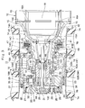
- each travel drive device for driving drive wheels of the dump truck for traveling is provided with an axle housing mounted in a non-rotating state on a vehicle body and having a tip end side opened to form a cylindrical spindle, a rotational shaft provided to axially extend in the spindle of the axle housing and driven and rotated by a drive source, a wheel mounting cylinder which is rotatably mounted on an outer peripheral side of the spindle through wheel support bearings and to which vehicle wheels are mounted, a reduction gear mechanism provided between the wheel mounting cylinder and the spindle to decelerate rotation of the rotational shaft, which is transmitted to the wheel mounting cylinder, and lubricant oil accommodated in a bottom side of the wheel mounting cylinder in a state of being reserved therein to lubricate the reduction gear mechanism (Patent Documents 1 and 2).
- the reduction gear mechanism is constituted by a multi-stage planetary gear reduction mechanism comprising a sun gear arranged on an outer peripheral side of the rotational shaft and rotating with rotation of the rotational shaft, a plurality of planetary gears meshing with the sun gear and a ring-shaped internal gear, and a carrier rotatably supporting the respective planetary gears through support pins.
- the carrier forming a part of a final-stage planetary gear reduction mechanism is configured to be mounted in a non-rotating state on an open end side of the spindle.
- the carrier used for the final-stage planetary gear reduction mechanism is mounted in a non-rotating state on the open end side of the spindle, the carrier and the spindle are coupled by a spline-coupling portion formed of a male spline and a female spline.
- this spline-coupling portion does not necessarily have sufficient strength in a case where a loading weight of the dump truck is increased to, for example, 250 tons or more, and a further improvement on the coupling portion is needed.
- a travel drive device for a dump truck which can enhance the strength to a rotational load by providing a separate coupling member between an open end side of a spindle and a carrier to improve durability and lifetime of an entire device.
- Another object of the present invention is to provide a travel drive device for dump truck which can guide lubricant oil between a planetary gear performing only a rotational movement without performing a revolving movement and a support pin to maintain a lubricating state between the planetary gear and the support pin, thus enhancing durability and reliability of an entire device.
- the present invention is applied to a travel drive device for a dump truck comprising an axle housing mounted in a non-rotating state on a vehicle body of a dump truck and having an end side opened to form a cylindrical spindle; a rotational shaft provided to axially extend in the spindle of the axle housing and driven and rotated by a drive source; a wheel mounting cylinder which is rotatably provided on an outer peripheral side of the spindle through wheel support bearings and to which wheels are mounted; a planetary gear reduction mechanism provided between the wheel mounting cylinder and the spindle to decelerate rotation of the rotational shaft, which is transmitted to the wheel mounting cylinder; and/or lubricant oil accommodated in a bottom side of the wheel mounting cylinder in a state of being reserved therein to lubricate the planetary gear reduction mechanism, the planetary gear reduction mechanism comprising a sun gear arranged on an outer peripheral side of the rotational shaft and rotating with rotation of the rotational shaft; a plurality of
- a characteristic of a construction adopted by the present invention lies in that a cylindrical coupling member which is formed as a coupling member for connecting the spindle and the carrier is provided between the spindle and the carrier and the rotational shaft is inserted in an inner peripheral side of the cylindrical coupling member, the cylindrical coupling member is provided with an opposing surface portion positioned higher than a liquid surface level of the lubricant oil and opposing through an axial gap a meshing part between the sun gear and each of the planetary gears, and an oil guide path is formed between each of the planetary gears and the opposing surface portion and guides the lubricant oil ejected from the meshing part between the sun gear and each of the planetary gears in between each of the planetary gears and each of the support pins.
- the spindle and the carrier can be connected in a non-rotating state by using the cylindrical coupling member made up of the single, independent member, increasing the strength to the rotational load, as well as improving durability and lifetime of an entire travel drive device.
- the lubricant oil axially ejected from the meshing part between the sun gear and each of the planetary gears can be guided through the oil guide path between the support pin and the planetary gear repeatedly performing only the rotational movement without performing the revolving movement. Therefore, the lubricating state can be maintained between the planetary gear and the support pin to enhance the durability and the reliability of the entire device.
- the cylindrical coupling member has the opposing surface portion opposing the meshing part between the sun gear and each of the planetary gears through the axial gap. Therefore, the lubricant oil ejected from the meshing part between the sun gear and each of the planetary gears can be trapped in the oil guide path between the opposing surface portion of the cylindrical coupling member and the end surface of each of the planetary gears to be guided between the planetary gear and the support pin. As a result, the planetary gear bearing provided between the planetary gear and the support pin can be maintained in a lubricating state.
- the sun gear is configured such that an axial one-side end surface projects closer to an axial one side of the opposing surface portion of the cylindrical coupling member than an end surface of each of the planetary gears to be close to the opposing surface portion of the cylindrical coupling member to narrow the gap.
- each of the planetary gears is provided with an annular step portion extending over an entire circumference between an outer diameter side section meshing with the sun gear and an inner diameter side section supported through a planetary gear bearing by the support pin, wherein the annular step portion forms a part of the oil guide path for guiding the lubricant oil ejected from the meshing part between the sun gear and each of the planetary gears in between each of the planetary gears and each of the support pins.
- the annular step portion provided in each of the planetary gears can efficiently trap the lubricant oil ejected from the meshing part between the sun gear and each of the planetary gears.
- the trapped lubricant oil can be guided between the planetary gear and the support pin with rotation (rotation on its axis) of the planetary gear.
- each of the planetary gears is provided with a plurality of oil reservoirs formed in a one-side end surface axially opposing the opposing surface portion of the cylindrical coupling member, wherein each of the oil reservoirs temporarily reserves the lubricant oil ejected from the meshing part between the sun gear and each of the planetary gears therein to form a part of the oil guide path.
- each of the plurality of the oil reservoirs formed in the end surface of each of the planetary gears can trap and temporarily reserve therein the lubricant oil ejected from the meshing part between the sun gear and each of the planetary gears.
- the lubricant oil can be guided between the planetary gear and the support pin with rotation (rotation on its axis) of the planetary gear.
- the opposing surface portion of the cylindrical coupling member is provided with a guide projection for beating off the lubricant oil ejected from the meshing part between the sun gear and each of the planetary gears toward a radial outside.
- the guide projection provided in the opposing surface portion of the cylindrical coupling member can beat off the lubricant oil ejected from the meshing part between the sun gear and each of the planetary gears toward the radial outside.
- the lubricating state can be maintained in the planetary gear bearing between the planetary gear and the support pin by guiding the beat lubricant oil in between each of the planetary gears and the support pin.
- the opposing surface portion of the cylindrical coupling member is provided with a plurality of oil guide groove portions radially extending from an inner peripheral side of the opposing surface portion toward the carrier to guide the lubricant oil ejected from the meshing part between the sun gear and each of the planetary gears in between each of the planetary gears and each of the support pins.
- the plurality of the oil guide groove portions provided in the opposing surface portion of the cylindrical coupling member radially extend from the inner peripheral side to the carrier side. Therefore, the lubricant oil ejected from the meshing part between the sun gear and each of the planetary gears can be guided in between each of the planetary gears and each of the support pins to maintain the planetary gear bearing to be in a lubricating state.
- a surface of the carrier opposing the planetary gear is provided with a plurality of oil guide groove portions radially extending from a side of the opposing surface portion of the cylindrical coupling member to a side of each of the support pins to guide the lubricant oil ejected from the meshing part between the sun gear and each of the planetary gears in between each of the planetary gears and each of the support pins.
- the plurality of the oil guide groove portions provided on the surface of the carrier opposing the planetary gear radially extend from the side of the opposing surface portion of the cylindrical coupling member to the side of each of the support pins. Therefore, the lubricant oil ejected from the meshing part between the sun gear and each of the planetary gears can be guided in between each of the planetary gears and each of the support pins to maintain the planetary gear bearing to be in a lubricating state.
- Fig. 1 to Fig. 5 show a travel drive device for a dump truck according to a first embodiment in the present invention.
- the dump truck 1 is constituted by including a vehicle body 2 having a strong frame structure and a vessel 3 as a loading platform liftably mounted on the vehicle body 2.
- the vessel 3 is formed, for example, as a large-sized container of an entire length of 9 to 13 meters for loading a large volume of heavy baggage such as crushed stones.
- a rear-side bottom portion of the vessel 3 is liftably (tiltably) connected to a rear end side of the vehicle body 2 through a connecting pin 4.
- a protector 3A is integrally provided in a front-side top portion of the vessel 3 in such a manner as to cover a cab 5 to be described later from the upper side.
- the cab 5 is provided in the front portion of the vehicle body 2 to be positioned under the protector 3A.
- the cab 5 forms an operator's room which an operator of the dump truck 1 gets in and off.
- An operator's seat, an activation switch, an accelerator pedal, a brake pedal, a handle for steering, and a plurality of operating levers (any of them is not shown) are provided inside the operator's room.
- the protector 3A of the vessel 3 has functions of protecting the cab 5 from flying stones such as rocks by substantially completely covering the cab 5 from the upper side, and protecting an operator inside the cab 5 at the falling-down of a vehicle (dump truck 1).
- Left and right front wheels 6 are rotatably provided on the front side of the vehicle body 2.
- Each front wheel 6 forms a steered wheel which is steered by an operator of the dump truck 1. Further, the front wheel 6 is formed in a tire diameter (outer diameter dimension), for example, as long as 3 to 4 meters in the same way as each of rear wheels 7 to be described later.
- a front-wheel side suspension 6SP formed by a hydraulic shock absorber is provided between the front portion of the vehicle body 2 and the front wheel 6.
- the left and right rear wheels 7 are rotatably provided on the rear side of the vehicle body 2.
- Each rear wheel 7 forms a drive wheel of the dump truck 1 which is driven and rotated integrally with a wheel mounting cylinder 18 by a travel drive device 11 to be described later as shown in Fig. 3 .
- Each rear wheel 7 is constituted by including dual tires of an inner tire 7A and an outer tire 7A, and rims 7B disposed in a radial inside of the respective tires 7A.
- a rear-wheel side suspension 7SP formed by a hydraulic shock absorber is provided between the rear portion of the vehicle body 2 and the rear wheel 7.
- An engine 8 is provided in the vehicle body 2 to be positioned under the cab 5.
- the engine 8 is constituted by, for example, a large-sized diesel engine and drives an on-board power generator and a hydraulic pump as a hydraulic source (any thereof is not shown) for rotation. Pressurized oil discharged from the hydraulic pump is supplied to hoist cylinders 9, a steering cylinder for power steering (not shown) and the like to be described later.
- the hoist cylinder 9 is a cylinder apparatus for lifting the vessel 3.
- the hoist cylinder 9 is positioned between the front wheel 6 and the rear wheel 7 to be disposed in each of both left and right sides of the vehicle body 2.
- Each of the hoist cylinders 9 is mounted between the vehicle body 2 and the vessel 3 to telescopically operate in the upper-lower direction.
- Each of the hoist cylinders 9 expands and contracts in the upper-lower direction by supply/discharge of the pressurized oil from/to the hydraulic pump to lift (tilt) the vessel 3 around the connecting pin 4 of the rear side.
- an operating oil tank 10 is mounted to a side of the vehicle body 2 or the like to be positioned under the vessel 3.
- Operating oil accommodated in the operating oil tank 10 is suctioned by the hydraulic pump and discharged therefrom to be pressurized, which is supplied/discharged to/from the hoist cylinder 9, the steering cylinder for power steering, and the like.
- the travel drive device 11 is constituted by including an axle housing 12, a wheel drive motor 16, a wheel mounting cylinder 18 and a reduction gear mechanism 24, which will be described later.
- the travel drive device 11 decelerates rotation of the wheel drive motor 16 by the reduction gear mechanism 24 and drives the rear wheels 7 as drive wheels of a vehicle together with the wheel mounting cylinder 18 by large rotational torque.
- Designated at 12 is the axle housing for the rear wheel 7, which is provided under the rear side of the vehicle body 2, and the axle housing 12 is formed in a cylindrical body which axially extends between the left and right rear wheels 7.
- the axle housing 12 is constituted by an intermediate cylindrical body 13 mounted to the rear side of the vehicle body 2 through the rear-wheel side suspension 7SP and a spindle 14 mounted to each of both left and right sides of the cylindrical body 13, which will be described later.
- the spindles 14 are provided respectively at axial both sides of the axle housing 12 and each spindle 14 is formed in a cylindrical body.
- the spindle 14 is constituted by including a large-diameter cylindrical portion 14A positioned at an axial one side, formed to be tapered and removably fixed to the cylindrical body 13 through bolts 15, and a circular cylindrical portion 14B which is formed integrally with the large-diameter cylindrical portion 14A at an axial other side and a tip end side of which is opened.
- the circular cylindrical portion 14B is arranged to axially extend within the wheel mounting cylinder 18 to be described later.
- An outer peripheral side of the circular cylindrical portion 14B rotatably supports the wheel mounting cylinder 18 in the side of the rear wheel 7 through wheel support bearings 20 and 21 to be described later.
- the spindle 14 has an outer peripheral side formed integrally with an annular flange portion 14C which radially outwardly projects from an intermediate section of the large-diameter cylindrical portion 14A in a length direction (axially) and to which a wet brake 47 is mounted, and with an annular step portion 14D provided to the circular cylindrical portion 14B at an axial one side for axially positioning a one-side retainer 50.
- a plurality of motor mounting seats 14E are formed integrally to the large-diameter cylindrical portion 14A at one side in an axial direction to radially inwardly project therefrom, and wheel drive motors 16 to be described later are mounted to the motor mounting seats 14E.
- an axial other side (tip end side) of the circular cylindrical portion 14B is formed as an open end, and an inner peripheral side thereof is provided with a female spline 14F (refer to Fig. 4 ) formed thereon.
- the female spline 14F is spline-coupled to a first male spline 53A of a cylindrical coupling member 53 to be described later.
- each tooth flank is subjected to a modification process (for example, a crowning process). Thereby, the female spline 14F can make a tooth contact of each tooth face with the first male spline 53A uniform.
- a circular inward projecting portion 14G is formed integrally on an inner peripheral side of the circular cylindrical portion 14B at an axial intermediate section, and a bearing retainer 45 to be described later is mounted to the inward projecting portion 14G through bolts.
- a radial hole 14H is formed in the lower part of the circular cylindrical portion 14B to penetrate and extend therethrough from an inner diameter side to an outer diameter side of the circular cylindrical portion 14B (radial direction of the circular cylindrical portion 14B), and a suction pipe 42 to be described later is inserted into the radial hole 14H.
- the wheel drive motor 16 is removably mounted in the axle housing 12, and the wheel drive motor 16 is used as a drive source of the rear wheel 7.
- the wheel drive motor 16 is formed of a large-sized electric motor driven and rotated by power supply from a power generator (not shown) mounted on the vehicle body 2.
- a power generator (not shown) mounted on the vehicle body 2.
- each of the wheel drive motors 16 is mounted within the spindle 14 to be position in each of left and right sides of the cylindrical body 13 to drive and rotate the left and right rear wheels 7 and 7 independently with each other.
- the wheel drive motor 16 is provided at an outer peripheral side with a plurality of mounting flanges 16A which are removably mounted to the motor mounting seat 14E of the spindle 14 by using bolts.
- the wheel drive motor 16 is configured to drive and rotate a rotational shaft 17 by supplying power from the power generator.
- the rotational shaft 17 is configured as an output shaft of the wheel drive motor 16 and is driven and rotated in the forward or backward direction by the wheel drive motor 16.
- the rotational shaft 17 is formed of a single, elongated, bar-shaped body extending in an axial direction (left and right directions) at the inner peripheral side of the spindle 14, and one end side of the rotational shaft 17 is connected to an output side of the wheel drive motor 16.
- the other end side of the rotational shaft 17 projects from an open end side of the circular cylindrical portion 14B forming the spindle 14 and to a projecting end of which a sun gear 26 to be described later is mounted.
- An axial intermediate section of the rotational shaft 17 is positioned between the wheel support bearings 20 and 21 to be described later and is rotatably supported in the spindle 14 by using a rotational shaft bearing 46 to be described later.
- the wheel mounting cylinder 18 is the wheel mounting cylinder rotating integrally with the rear wheel 7 as a wheel.
- the wheel mounting cylinder 18 forms a so-called wheel hub, and has the outer peripheral side to which each rim 7B of the rear wheel 7 is removably mounted by means such as press-fitting.
- the wheel mounting cylinder 18 is integrally formed of a hollow cylindrical portion 18A axially extending between the wheel support bearings 20 and 21 to form a hollow structure, and an extending cylindrical portion 18B axially extending from an outer peripheral end portion of the hollow cylindrical portion 18A toward an internal gear 35 to be described later. Accordingly, the wheel mounting cylinder 18 is formed as an integral object in a stepped cylindrical shape as a whole.
- the internal gear 35 and an outer drum 22 to be described later are integrally fixed to the extending cylindrical portion 18B of the wheel mounting cylinder 18 by using long bolts 23. Therefore, the wheel mounting cylinder 18 is rotated integrally with the internal gear 35. That is, rotation of large torque obtained by decelerating the rotation of the wheel drive motor 16 with the reduction gear mechanism 24 is transmitted to the wheel mounting cylinder 18 through the internal gear 35. Therefore, the wheel mounting cylinder 18 rotates the rear wheel 7 as the drive wheel in a vehicle with the large rotational torque.
- a rim spacer 19 is formed by a cylindrical ring.
- the rim spacer 19 is arranged at the outer peripheral side of the wheel mounting cylinder 18 to ensure a predetermined axial gap between an inner tire 7A and an outer tire 7A in the rear wheel 7. That is, as shown in Fig. 3 , the rim spacer 19 is sandwiched tightly between a rim 7B in an axial inside and a rim 7B in an axial outside of the rear wheel 7 to keep a space therebetween to be axially constant.
- Denoted at 20 and 21 are the wheel support bearings for rotatably supporting the wheel mounting cylinder 18 on the outer peripheral side of the spindle 14 and the wheel support bearings 20 and 21 are configured, for example, by using the same tapered roller bearing or the like.
- the wheel support bearings 20 and 21 are arranged to be spaced apart axially between the circular cylindrical portion 14B of the spindle 14 and the hollow cylindrical portion 18A of the wheel mounting cylinder 18. That is, the one wheel support bearing 20 is positioned to the annular step portion 14D of the spindle 14 through the one-side retainer 50 to be described later and the other wheel support bearing 21 is positioned to an open end-side outer periphery of the circular cylindrical portion 14B through an end retainer 51 to be described later.
- Each inner race of the wheel support bearings 20 and 21 is axially positioned between the retainers 50 and 51 to the circular cylindrical portion 14B of the spindle 14.
- Each outer race of the wheel support bearings 20 and 21 is axially positioned to the hollow cylindrical portion 18A of the wheel mounting cylinder 18. Therefore, the wheel mounting cylinder 18 is axially positioned to the spindle 14 by using the wheel support bearings 20 and 21 and the retainers 50 and 51, and is supported to the spindle 14 to be rotatable in a circumferential direction thereto.
- the outer drum 22 forms a part of the wheel mounting cylinder 18 together with the internal gear 35. As shown in Fig. 3 , the outer drum 22 is mounted in a position at an axial outside of the wheel mounting cylinder 18 to sandwich the internal gear 35 to be described later therebetween and is removably fixed to the wheel mounting cylinder 18 by using a plurality of long bolts 23.
- the reduction gear mechanism 24 is constituted by a first-stage planetary gear reduction mechanism 25 and a final-stage planetary gear reduction mechanism 33 as a second stage, which will be described later.
- the reduction gear mechanism 24 decelerates rotation of the wheel drive motor 16 (that is, rotational shaft 17), which is transmitted to the wheel mounting cylinder 18 at the side of the rear wheel 7. Therefore, the wheel mounting cylinder 18 at the side of the rear wheel 7 is driven and rotated together with the rear wheel 7 by a large rotational force (torque) obtained by the deceleration.
- Denoted at 25 is the first-stage planetary gear reduction mechanism forming the reduction gear mechanism 24, and the first-stage planetary gear reduction mechanism 25 is constituted by the sun gear 26 spline-coupled to the tip end side as a free end of the rotational shaft 17, a plurality (for example, three or four pieces) of planetary gears 28 meshed with the sun gear 26 and a ring-shaped internal gear 27, and a carrier 30 rotatably supporting the respective planetary gears 28 through support pins 29.
- the carrier 30 is removably fixed at its outer peripheral side to an open end (an end surface at an axially outside) of the outer drum 22 integral with the wheel mounting cylinder 18 through bolts, and rotates integrally with the wheel mounting cylinder 18 and the outer drum 22.
- a disk-shaped lid plate 31 is removably mounted to the inner peripheral side of the carrier 30. The lid plate 31 is removed from the carrier 30, for example, at the time of inspection or maintenance of meshing parts between the sun gear 26 and the planetary gears 28.
- the ring-shaped internal gear 27 is formed by using a ring gear to surround the sun gear 26 and the respective planetary gears 28 from a radial outside, and the internal gear 27 is relatively rotatably located as having a radial gap to an inner peripheral surface of the outer drum 22.
- the rotation (revolving movement) of the internal gear 27 is transmitted to a second-stage planetary gear reduction mechanism 33 through a coupling 32 to be described later.
- the first-stage planetary gear reduction mechanism 25 converts the rotation of the sun gear 26 into a rotating movement of each of the planetary gears 28 and a revolving movement thereof. Further, the rotating movement (rotation) of each of the planetary gears 28 is transmitted to the ring-shaped internal gear 27 as a decelerated rotation. The rotation of the internal gear 27 is transmitted to the second-stage planetary gear reduction mechanism 33 through the coupling 32 to be described later. On the other hand, the revolving movement of each of the planetary gears 28 is transmitted to the outer drum 22 in the side of the wheel mounting cylinder 18 by way of rotation of the carrier 30.
- the coupling 32 rotates integrally with the first-stage internal gear 27, and the coupling 32 is in the form of an annular rotation transmitting member which is located in a position between the first-stage planetary gear reduction mechanism 25 and the second-stage planetary gear reduction mechanism 33. That is, an outer peripheral side of the coupling 32 is spline-coupled to the first-stage internal gear 27. An inner peripheral side of the coupling 32 is spline-coupled to a second-stage sun gear 34 to be described later.
- the coupling 32 transmits rotation of the first-stage internal gear 27 to the second-stage sun gear 34 to rotate the sun gear 34 integrally with the first-stage internal gear 27.
- a plurality of oil holes may be formed in the coupling 32 to circulate lubricant oil 100 to be described later in the front-rear direction (axial direction).
- this planetary gear reduction mechanism 33 is located between the rotational shaft 17 and the wheel mounting cylinder 18 through the first-stage planetary gear reduction mechanism 25 and decelerates the rotation of the rotational shaft 17 together with the first-stage planetary gear reduction mechanism 25.
- the second-stage planetary gear reduction mechanism 33 is constituted by the cylindrical sun gear 34 which is positioned on an outer peripheral side of the rotational shaft 17 to be mounted coaxially with the rotational shaft 17 and rotates integrally with the coupling 32 according to rotation of the rotational shaft 17, a plurality of planetary gears 36 (only one of which is shown in the figure) which are meshed with the sun gear 34 and the ring-shaped internal gear 35, and a carrier 38 which rotatably supports the respective planetary gears 36 through support pins 37.
- a planetary gear bearing 39 is provided between an inner peripheral side of each of the planetary gears 36 and each of the support pins 37, which is composed of, for example, two conical bearings backsides of which oppose to each other.
- the planetary gear bearing 39 supports the planetary gear 36 together with the support pin 37 to be rotatable to the carrier 38.
- Each of the planetary gears 36 is provided with an annular step portion 36A extending over an entire circumference in the radial intermediate portion (that is, an intermediate portion between an outer diameter side section meshing with the sun gear 34 and an inner diameter side section supported through the planetary gear bearing 39 by the support pin 37).
- the annular step portion 36A temporarily traps the lubricant oil 100 to be described later on the inner surface and forms a part of an oil guide path 55 to be described later.
- the sun gear 34 has an end surface 34A in the axial one-side projecting closer to a side of an opposing surface portion 53E to be described later than the planetary gear 36 to be arranged in a position close to the opposing surface portion 53E. Therefore, the lubricant oil 100 axially (for example, in the direction of an arrow A in Fig. 5 ) ejected from a meshing part 40 between the sun gear 34 and the planetary gear 36 does not escape to a side of a stepped hole 53D of the cylindrical coupling member 53, but is guided by the oil guide path 55 to be trapped or collected in the annular step portion 36A of the planetary gear 36.
- the second-stage internal gear 35 is formed by using a ring gear to surround the sun gear 34 and the respective planetary gears 36 from a radial outside.
- the internal gear 35 is integrally fixed between the extending cylindrical portion 18B forming a part of the wheel mounting cylinder 18 and the outer drum 22 by using the long bolts 23. Further, internal teeth formed over the entire periphery on the inner peripheral side of the internal gear 35 are meshed with the respective planetary gears 36.
- the second-stage carrier 38 as a final stage is configured by including annular support plates 38A and 38B, a plurality of pin mounting hole portions 38C and 38D (only one of each is shown in the figure), and a plurality (for example, three or four pieces) of connecting portions 38E.
- the annular support plates 38A and 38B are made up of two plate bodies each having a different plate thickness and are arranged to axially oppose with each other.
- the pin mounting hole portions 38C and 38D are arranged by constant intervals in the circumferential direction for arranging each of the planetary gears 36 between the support plates 38A and 38B. Both end sides of each support pin 37 are mounted to be fitted in the pin mounting hole portions 38C and 38D.
- the connecting portions 38E are arranged to be spaced in the circumferential direction from each pin mounting hole portion 38C and 38D to connect the annular support plates 38A and 38B integrally.
- the female spline 38F is formed on an inner peripheral side of the support plate 38A in the carrier 38.
- the female spline 38F is spline-coupled to second male spline 53B of the cylindrical coupling member 53 to be described later.
- each tooth flank is subjected to a modification process (for example, crowning process). Thereby, a tooth contact in each tooth flank between the second male spline 53B and the female spline 38F can be made uniform over an entire tooth width.
- the support plate 38A in the carrier 38 is provided with an annular projecting portion 38G in an inner peripheral side of an end surface as an axial other side (an end surface axially opposing the planetary gear bearing 39).
- the annular projecting portion 38G axially projects to a side of the annular step portion 36A of the planetary gear 36 in the same way with an annular projecting portion 53F of the cylindrical coupling member 53 to be described later.
- the female spline 38F in the carrier 38 is also formed in a position of the annular projecting portion 38G. Therefore, a tooth width (axial length) of the female spline 38F is longer by an axial projection dimension of the annular projecting portion 38G.
- the annular projecting portions 38G and 53F can function as steps for temporarily reserving the oil liquid in the substantially same way with the annular step portion 36A in the planetary gear 36 to temporarily trap the lubricant oil 100 to be described later.
- the carrier 38 is spline-coupled through the cylindrical coupling member 53 to be described later to the circular cylindrical portion 14B of the spindle 14, thereby restraining revolving movements of the respective planetary gears 36 (rotation of the carrier 38). Therefore, as the sun gear 34 rotates integrally with the coupling 32, the second-stage planetary gear reduction mechanism 33 converts the rotation of the sun gear 34 into rotation of each of the planetary gears 36. The rotation of each of the planetary gears 36 is transmitted to the second-stage internal gear 35, and the internal gear 35 is decelerated for rotation. Therefore, the rotational torque of large output decelerated at the two-stage through the first and second-stage planetary gear reduction mechanisms 25 and 33 is transmitted to the wheel mounting cylinder 18 to which the internal gear 35 is fixed.
- the lubricating system is constituted by including a partition wall 41, the suction pipe 42, a supply pipe 43, an inner retainer 44, the bearing retainer 45, and the rotational shaft bearing 46.
- the lubricant oil 100 is accommodated in a bottom side of the wheel mounting cylinder 18 in a state of being reserved therein, and the respective planetary gear reduction mechanisms 25 and 33 operate in a state where the lubricant oil 100 is supplied all the time.
- an oil surface of the lubricant oil 100 is lower than, for example, the lowest section of the circular cylindrical portion 14B forming the spindle 14 and is set in a position where a lower side section of each of the wheel support bearings 20 and 21 is immersed.
- the lubricant oil 100 can be stirred by the wheel mounting cylinder 18 and the respective planetary gear reduction mechanisms 25 and 33 to perform a so-called stirring lubrication, and a stirring resistance of the lubricant oil 100 can be restricted to be small.
- the partition wall 41 is provided in the spindle 14.
- the partition wall 41 is formed of an annular plate and is removably fixed at its outer peripheral side to an inner peripheral side of the large-diameter cylindrical portion 14A of the spindle 14 by using bolts.
- the partition wall 41 is configured to divide an inside of the spindle 14 into a motor accommodating space portion 41A positioned at its axial one side for accommodating the wheel drive motor 16 and a cylindrical space portion 41B positioned at its axial other side for communicating with the inside of the wheel mounting cylinder 18 all the time.
- the suction pipe 42 collects the lubricant oil 100 reserved in the wheel mounting cylinder 18 and the suction pipe 42 has one side in the length direction axially extending within the cylindrical body 13 of the axle housing 12 to be connected to a suction side of a lubricating pump (not shown).
- An intermediate section of the suction pipe 42 in the length direction axially extends within the spindle 14 toward the side of the wheel mounting cylinder 18.
- a tip end side 42A (the other side in the length direction) of the suction pipe 42 is bent in an L-letter shape downward from a lower side of the rotational shaft 17 to penetrate through the radial hole 14H of the spindle 14. Therefore, the suction pipe 42 is immersed at the tip end side 42A in the lubricant oil 100 in the wheel mounting cylinder 18 to collect the lubricant oil 100 to the side of the lubricating pump.
- the supply pipe 43 supplies lubricant oil 100 into the reduction gear mechanism 24.
- the supply pipe 43 is located above the suction pipe 42 and the rotational shaft 17 in the spindle 14, a tip end side 43A of which is inserted into the cylindrical coupling member 53 to be described later.
- One side (base end side) in the length direction of the supply pipe 43 is connected to a discharge side of the lubricating pump.
- the lubricant oil 100 discharged from the lubricating pump is supplied from a tip end side 43A (the other side in the length direction) of the supply pipe 43 toward the cylindrical coupling member 53 to be described later, that is, toward the planetary gear reduction mechanisms 25 and 33.
- the lubricant oil 100 reserved in a bottom side of the wheel mounting cylinder 18 is suctioned from a tip end side 42A of the suction pipe 42 by driving the lubricating pump, and the lubricant oil 100 suctioned by the lubricating pump is cooled by an oil cooler (not shown).
- the cooled lubricant oil 100 is thereafter supplied through the supply pipe 43 to the planetary gear reduction mechanisms 25 and 33, thus lubricating the planetary gear reduction mechanisms 25 and 33.
- Denoted at 44 is the inner retainer provided to fit into an axial intermediate section of the rotational shaft 17, and denoted at 45 is an outer bearing retainer located at the outer peripheral side of the inner retainer 44 through the rotational shaft bearing 46.
- the inner retainer 44 is press-fitted at its inner peripheral side into the intermediate section of the rotational shaft 17 to rotate integrally with the rotational shaft 17.
- the outer bearing retainer 45 is fixed to an inward projecting portion 14G of the spindle 14 by using a plurality of bolts (not shown).
- the bearing retainer 45 is formed as an annular ring body.
- An outer race mounting portion 45A is mounted on an inner peripheral side of the bearing retainer 45 in a state of preventing the outer race of the rotational shaft bearing 46 from pulling out of the bearing retainer 45.
- a cylindrical projecting portion 45B is provided on an outer peripheral side of the bearing retainer 45 to project toward an end surface of the cylindrical coupling member 53 to be described later at an axial one side.
- the cylindrical projecting portion 45B forms a positioning projection for axially positioning the cylindrical coupling member 53 inside the circular cylindrical portion 14B of the spindle 14.
- the bearing retainer 45 is provided with insert holes 45C and 45D positioned to radially (upper and lower directions in Fig. 4 ) oppose with each other.
- the supply pipe 43 is mounted to penetrate through the insert hole 45C.
- the suction pipe 42 is mounted to penetrate through the insert hole 45D.
- the bearing retainer 45 is provided with a radial notched portion 45E in a position under the insert hole 45D. The suction pipe 42 is inserted through the notched portion 45E into the radial hole 14H of the spindle 14.
- mid-sections of the suction pipe 42 and the supply pipe 43 extend to axially penetrate through the bearing retainer 45, so that the suction pipe 42 and the supply pipe 43 are positioned in the spindle 14 through the bearing retainer 45.
- a plurality of bolt through holes are formed in the bearing retainer 45.
- the bearing retainer 45 is fixed to the inward projecting portion 14G of the spindle 14 by a plurality of bolts inserted into the bolt through holes.
- the rotational shaft bearing 46 is located between the inner retainer 44 in the side of the rotational shaft 17 and the bearing retainer 45 in the side of the spindle 14.
- the rotational shaft bearing 46 rotatably supports the axial intermediate section of the rotational shaft 17 through the inner retainer 44 and the outer bearing retainer 45 in the circular cylindrical portion 14B of the spindle 14. Therefore, the core swing in the axial intermediate section of the long rotational shaft 17 can be suppressed, and the long rotational shaft 17 can transmit stable rotation of the rotational shaft 17 to the first-stage sun gear 26.
- a wet brake 47 applies braking forces to rotation of the wheel mounting cylinder 18, and the wet brake 47 is constituted by a hydraulic brake of a wet multi-plate type.
- the wet brake 47 is provided through a brake hub 48 to be described later between the spindle 14 in the axle housing 12 and the wheel mounting cylinder 18.
- the wet brake 47 applies braking forces to the brake hub 48 rotating together with the wheel mounting cylinder 18.
- the brake hub 48 forms a part of the wet brake 47 and rotates together with the wheel mounting cylinder 18.
- the brake hub 48 is formed as a cylindrical body axially extending between the spindle 14 and the wet brake 47.
- the axial other side of the brake hub 48 is removably fixed to the hollow cylindrical portion 18A of the wheel mounting cylinder 18 by a plurality of bolts 49.
- the one-side retainer 50 positions an inner race of the wheel support bearing 20 to the circular cylindrical portion 14B of the spindle 14. As shown in Fig. 3 , the one-side retainer 50 is provided to be fitted into the outer peripheral surface of the circular cylindrical portion 14B. An axial one side of the one-side retainer 50 abuts against the annular step portion 14D of the spindle 14. Meanwhile, an axial other side of the one-side retainer 50 axially abuts against the inner race of the wheel support bearing 20. Therefore, in regard to the wheel support bearing 20, the outer race is axially positioned by the hollow cylindrical portion 18A of the wheel mounting cylinder 18 and the inner race is axially positioned by the one-side retainer 50.
- the end retainer 51 is mounted to an end opening side of the spindle 14 through a plurality of bolts 52 and forms the other-side retainer.
- the end retainer 51 is fixed to the circular cylindrical portion 14B of the spindle 14 and axially positions the inner race of the wheel support bearing 21 with the outer peripheral side of the circular cylindrical portion 14B. That is, in regard to the wheel support bearing 21, the outer race is axially positioned by the hollow cylindrical portion 18A of the wheel mounting cylinder 18 and the inner race is axially positioned by the end retainer 51.
- the wheel mounting cylinder 18 is rotatably supported by the wheel support bearings 20 and 21 in a state of being positioned between the one-side retainer 50 and the end retainer 51.
- the end retainer 51 is formed as an annular ring body. An inner peripheral side of the end retainer 51 is provided with a retaining portion 51A projecting inward in a radial direction in such a manner as to abut against a step portion 53C of the cylindrical coupling member 53 to be described later.
- the retaining portion 51A makes surface contact with the annular step portion 53C over the entire circumference for performing an operation of retaining the cylindrical coupling member 53 at the open side of the spindle 14.
- a plurality of bolt through holes are bored in the end retainer 51.
- the end retainer 51 is fixed to the circular cylindrical portion 14B of the spindle 14 by the plurality of bolts 52 inserted into the bolt through holes.
- the cylindrical coupling member 53 is removably provided between the open side of the spindle 14 and the carrier 38.
- the cylindrical coupling member 53 is formed as a stepped cylindrical body formed of a single, separate member independently of the spindle 14 and the carrier 38, and the rotational shaft 17 is inserted with a gap in the inner peripheral side of the cylindrical coupling member 53.
- an outer periphery thereof at one side in an axial direction is spline-coupled to the open end inner peripheral side of the spindle 14 and an outer periphery thereof at the other side in the axial direction is spline-coupled to the inner peripheral side of the carrier 38.
- a stepped hole 53D is provided on an inner peripheral side of the cylindrical coupling member 53 to have a large diameter at an axial one side and a small diameter at the axial other side.
- the rotational shaft 17 and a tip end side 43A of the supply pipe 43 are inserted into the stepped hole 53D.
- the cylindrical coupling member 53 is arranged in a position all the time higher than a liquid surface level of the lubricant oil 100 accommodated in the wheel mounting cylinder 18.
- the opposing surface portion 53E in the cylindrical coupling member 53 is provided with the annular projecting portion 53F positioned in an outer diameter side thereof to axially project to a side of the annular step portion 36A of the planetary gear 36.
- the second male spline 53B is also formed in a position of the annular projecting portion 53F. Thereby, the second male spline 53B is longer in a tooth width (axial length) by an axial projection dimension of the annular projecting portion 53F.
- the female spline 38F in the carrier 38 is also provided with the similar annular projecting portion 38G on the end surface of the support plate 38A.
- Denoted at 54 is the axial gap formed between the opposing surface portion 53E of the cylindrical coupling member 53 and the end surface 34A of the sun gear 34 at one side, and the gap 54 is formed to be narrower as compared to the oil guide path 55 to be described later. That is, the gap 54 forms a dam in such a manner that the lubricant oil 100 ejected from the meshing part 40 between the sun gear 34 and each of the planetary gears 36 flows toward the oil guide path 55, and prevents the lubricant oil 100 from escaping toward a side of the stepped hole 53D of the cylindrical coupling member 53 (toward a radial inside of the sun gear 34).
- Denoted at 55 is the oil guide path adopted in the first embodiment, and is formed between a one-side end surface of each of the planetary gears 36 and the opposing surface portion 53E of the cylindrical coupling member 53.
- the oil guide path 55 guides the lubricant oil ejected in the direction of an arrow A (refer to Fig. 5 ) from the meshing part 40 between the sun gear 34 and each of the planetary gears 36, to the planetary gear bearing 39 between the planetary gear 36 and the support pin 37, thus maintaining the planetary gear bearing 39 to be in an oil supplied state.
- the oil guide path 55 is constituted by including the annular step portion 36A of the planetary gear 36, the annular projecting portion 38G of the carrier 38, and the opposing surface portion 53E and the annular projecting portion 53F of the cylindrical coupling member 53.
- the travel drive device 11 for the dump truck 1 has the aforementioned configuration, and next, an operation thereof will be explained.
- the hydraulic pump as a hydraulic source is driven and rotated, and electric power is generated by a power generator (any thereof is not shown).
- a power generator any thereof is not shown.
- the electric power is supplied from the power generator to the wheel drive motor 16, and thereby the wheel drive motor 16 is activated to rotate the rotational shaft 17.
- the rotation of the rotational shaft 17 is transmitted from the sun gear 26 of the first-stage planetary gear reduction mechanism 25 to the respective planetary gears 28 in a state of being decelerated, and the rotation of each of the planetary gears 28 is transmitted through the internal gear 27 and the coupling 32 to the sun gear 34 of the second-stage planetary gear reduction mechanism 33 in a state of being decelerated.
- the rotation of the sun gear 34 is transmitted to the respective planetary gears 36 in a state of being decelerated.
- each of the planetary gears 36 only rotates around the sun gear 34, and rotation decelerated by the rotation of each of the planetary gears 36 is transmitted to the internal gear 35 fixed to the wheel mounting cylinder 18.
- the wheel mounting cylinder 18 rotates with the rotational torque of large output decelerated by the two-stage through the first and second-stage planetary gear reduction mechanisms 25 and 33.
- the left and right rear wheels 7 as the drive wheel can be rotated together with the wheel mounting cylinder 18 to drive the dump truck 1 for traveling.
- the rotational shaft 17 axially extending from the spindle 14 toward an inside of the wheel mounting cylinder 18 has an axial intermediate section rotatably supported through the rotational shaft bearing 46 by the inner retainer 44 and the outer bearing retainer 45. Therefore, when the rotational shaft 17 rotates in high speeds, the radial torsion or the core swing of the axial intermediate section to be generated due to eccentricity of the rotational shaft 17 can be suppressed at the position of the rotational shaft bearing 46 to enhance durability of the rotational shaft 17.
- the lubricant oil 100 reserved in the wheel mounting cylinder 18 is stirred upwards in order by rotation of the wheel mounting cylinder 18, the respective planetary gears 28 and 36 in the first and second-stage planetary gear reduction mechanisms 25 and 33. Therefore, the lubricant oil 100 is supplied to meshing sections of the respective gears, the wheel support bearings 20 and 21 between the circular cylindrical portion 14B of the spindle 14 and the wheel mounting cylinder 18. At this time, in the second planetary gear reduction mechanism 33, the lubricant oil 100 is supplied also to the meshing part 40 between the sun gear 34 and each of the planetary gears 36 (refer to Fig. 4 and Fig. 5 ). Thereafter, the lubricant oil 100 drops downwards and is reserved in the bottom side of the wheel mounting cylinder 18.
- the lubricant oil 100 accommodated in the bottom side of the wheel mounting cylinder 18 is suctioned up from the tip end side 42A of the suction pipe 42 by the lubricating pump.
- the lubricant oil 100 is cooled by an oil cooler, and subsequently, is discharged to the side of the supply pipe 43. Therefore, the lubricant oil 100 can be sequentially supplied from the tip end side 43A of the supply pipe 43 toward the reduction gear mechanism 24 (namely, the first and second-stage planetary gear reduction mechanisms 25 and 33) in the wheel mounting cylinder 18.
- the dump truck 1 in a case of decelerating a traveling speed of the dump truck 1 in the middle of the traveling, in some cases the dump truck 1 can not be sufficiently decelerated simply by decelerating rotation of the wheel drive motor 16. In such a case, an operator of the dump truck 1 depresses the brake pedal to supply a brake pressure (pressurized oil) to the wet brake 47 composed of a hydraulic brake of a wet multi-plate type. Thereby, the wet brake 47 can apply braking forces to the brake hub 48 rotating integrally with the wheel mounting cylinder 18.
- a brake pressure pressurized oil
- the travel drive device 11 for the dump truck 1 is structured such that the carrier 38 used for the final-stage planetary gear reduction mechanism 33 is mounted in a non-rotating state on the open end side of the spindle 14, and therefore the carrier 38 and the spindle 14 are coupled by a spline-coupling portion.
- this spline-coupling portion used in the conventional art does not necessarily have sufficient strength in a case where a loading weight of the dump truck 1 is increased to, for example, 250 tons or more, and a further improvement on the coupling portion is needed.
- the cylindrical coupling member 53 which is formed as an independent, single coupling member, is provided between the open side of the spindle 14 and the carrier 38, wherein the spindle 14 and the carrier 38 are spline-coupled by the cylindrical coupling member 53.
- the oil guide path 55 is formed between a one-side end surface of each of the planetary gears 36 and the opposing surface portion 53E of the cylindrical coupling member 53.
- the oil guide path 55 guides the lubricant oil ejected in the direction of an arrow A (refer to Fig. 5 ) from the meshing part 40 between the sun gear 34 and each of the planetary gears 36, to the planetary gear bearing 39 between the planetary gear 36 and the support pin 37.
- the oil guide path 55 is constituted by including the annular step portion 36A formed in the radial intermediate section of the planetary gear 36, the annular projecting portion 38G of the carrier 38, and the opposing surface portion 53E and the annular projecting portion 53F of the cylindrical coupling member 53.
- the narrow gap 54 is formed between the opposing surface portion 53E of the cylindrical coupling member 53 and the sun gear 34, and the gap 54 forms a dam in such a manner that the lubricant oil 100 ejected from the meshing part 40 flows toward the oil guide path 55.
- the cylindrical coupling member 53 is formed as a stepped cylindrical body by a single member, an axial one side thereof is positioned by the cylindrical projecting portion 45B of the bearing retainer 45, and an axial other side thereof is positioned through the annular step portion 53C by the end retainer 51.
- the cylindrical coupling member 53 is supported in a non-rotating state such that the first male spline 53A is spline-coupled to the female spline 14F of the spindle 14 and the second male spline 53B is spline-coupled to the female spline 38F of the carrier 38.
- the cylindrical coupling member 53 by configuring the cylindrical coupling member 53 in this manner, it is not required to integrally provide the cylindrical projecting portion having the male spline on the outer peripheral side, which is different from the carrier used in the conventional art, and therefore it is possible to simplify the shape of the carrier 38.
- the cylindrical coupling member 53 is a member separated from the spindle 14 and the carrier 38, the cylindrical coupling member 53 can be formed in a simple shape. Therefore, when the male splines 53A and 53B are molded on the outer peripheral side of the cylindrical coupling member 53, a hob cutter process can be adopted. Further, in regard to the male splines 53A and 53B, it is easy to execute the modification process to the tooth flank called crowning or relieving for preventing partial contact in the tooth flank.
- the bearing retainer 45 supports the outer race of the rotational shaft bearing 46 on the inner peripheral side of the spindle 14, but is provided with a cylindrical projecting portion 45B projecting toward an end surface of the cylindrical coupling member 53 at an axial one side.
- the cylindrical projecting portion 45B abuts against the end surface of the cylindrical coupling member 53, and thereby the cylindrical coupling member 53 can be axially positioned in the spindle 14.
- the cylindrical coupling member 53 is structured such that the end surface at the axial one side (side of the first male spline 53A) abuts against the cylindrical projecting portion 45B of the bearing retainer 45 and the annular step portion 53C at the axial intermediate section abuts against the retaining portion 51A of the end retainer 51.
- the cylindrical coupling member 53 can be sandwiched from the axial both sides between the cylindrical projecting portion 45B and the retaining portion 51A. Therefore, the cylindrical coupling member 53 is accurately positioned in a state where the axial intermediate section is stable to an open end of the spindle 14.
- the rotation of the carrier 38 is restrained by the spindle 14, and thereby the planetary gear 36 repeatedly performs only the rotation without performing the revolving movement.
- the lubricant oil ejected in the direction of an arrow A (refer to Fig. 5 ) from the meshing part 40 between the sun gear 34 and the planetary gear 36 can be guided through the aforementioned oil guide path 55 to the support pin 37 and the planetary gear bearing 39. Therefore, the lubricating state can be maintained in the planetary gear bearing 39 between the planetary gear 36 and the support pin 37 to enhance the durability and the reliability of the entire travel drive device 11.
- the cylindrical coupling member 53 has the opposing surface portion 53E opposing the meshing part 40 between the sun gear 34 and each of the planetary gears 36 through the axial gap 54. Therefore, the gap 54 dams the lubricant oil ejected from the meshing part 40 between the sun gear 34 and each of the planetary gears 36, and traps the lubricant oil in such a manner as to flow toward the oil guide path 55. Therefore, the lubricant oil can be guided between the planetary gear 36 and the support pin 37. Accordingly, the planetary gear bearing 39 can be maintained in a lubricating state.
- the one-side end surface 34A of the sun gear 34 in the planetary gear reduction mechanism 33 projects closer to the axial one side of the cylindrical coupling member 53 than the end surface of each of the planetary gears 36 to be close to the opposing surface portion 53E of the cylindrical coupling member 53, that is, to narrow the gap 54. Therefore, the gap 54 guides the lubricant oil ejected in the direction of an arrow A (refer to Fig. 5 ) from the meshing part 40 between the sun gear 34 and each of the planetary gears 36 to the oil guide path 55, and the oil guide path 55 can supply the lubricant oil to the planetary gear bearing 39 between the planetary gear 36 and the support pin 37.
- the planetary gear 36 can be maintained to be in a lubricating state.
- the lubricant oil 100 attached on the tooth flank of the sun gear 34 projecting from each of the planetary gears 36 can be splashed to the planetary gear 36 by a function of a centrifugal force generated by rotation of the sun gear 34 to stably maintain the planetary gear 36 to be in a lubricating state without any influence of the travelling speed of the dump truck 1, the inclination of the vehicle body 2 or the like.
- annular step portion 36A provided in the radial intermediate section of each of the planetary gears 36 can trap the lubricant oil ejected from the meshing part 40 between the sun gear 34 and each of the planetary gears 36 through the opposing surface portion 53E and the annular projecting portion 53F of the cylindrical coupling member 53, and can guide the trapped lubricant oil to the planetary gear bearing 39 with rotation (rotation on its axis) of the planetary gear 36.
- the lubricant oil is guided between the planetary gear 36 performing repetition of only rotation without performing the revolving movement and the support pin 37 in the planetary gear reduction mechanism 33, and thereby the planetary gear bearing 39 between the planetary gear 36 and the support pin 37 can be maintained in a lubricating state to enhance durability and reliability of the entire travel drive device 11.
- the cylindrical coupling member 53 as a separate coupling member between the open end side of the spindle 14 and the carrier 38, the strength to the rotational load can be increased to enhance durability and lifetime of the entire device.
- Fig. 6 shows a second embodiment according to the present invention.
- the present embodiment comprises a guide projection provided in an opposing surface of a cylindrical coupling member for beating off lubricant oil to a radial outside.
- the component elements that are identical to those of the foregoing first embodiment will be simply denoted by the same reference numerals to avoid repetitions of similar explanations.
- a sun gear adopted in the second embodiment denoted at 61 is a sun gear adopted in the second embodiment, and the sun gear 61 is configured substantially in the same way with the sun gear 34 described in the first embodiment.
- An axial one-side end surface 61A of the sun gear 61 projects closer to an opposing surface portion 62E to be described later than the planetary gear 36.
- the projection dimension is made smaller than that of the sun gear 34 described in the first embodiment. That is, since a guide projection 62G is provided in a cylindrical coupling member 62 to be described later, an axial entire length dimension (projection dimension) of the sun gear 61 is formed smaller by the projection dimension of the guide projection 62G.
- the cylindrical coupling member 62 is the cylindrical coupling member removably provided between the open side of the spindle 14 and the carrier 38.
- the cylindrical coupling member 62 is configured substantially in the same way with the cylindrical coupling member 53 described in the first embodiment, and includes first male spline (not shown), second male spline 62B, an annular step portion (not shown), a stepped hole 62D, the opposing surface portion 62E, and an annular projecting portion 62F.
- the opposing surface portion 62E of the cylindrical coupling member 62 opposes the meshing part 40 between the sun gear 61 and each of the planetary gears 36 through the axial gap 54, and the annular projecting portion 62F axially projecting toward a side of the annular step portion 36A of the planetary gear 36 is provided in the outer diameter side of the opposing surface portion 62E.
- the cylindrical coupling member 62 in this case differs from the first embodiment in a point where the guide projection 62G which projects toward an axial one-side end surface 61A of the sun gear 61 is formed in an inner diameter side of the opposing surface portion 62E.
- the guide projection 62G is configured of an annular projection extending over an entire circumference along the stepped hole 62D of the cylindrical coupling member 62, and is arranged in a position slightly closer to a radial inside than the meshing part 40 between the sun gear 61 and each of the planetary gears 36.
- the guide projection 62G beats off a part of the lubricant oil ejected in the direction of an arrow A (refer to Fig. 6 ) from the meshing part 40 between the sun gear 61 and each of the planetary gears 36 toward a radial outside, and causes the annular step portion 36A of the planetary gear 36 to trap and collect the beat lubricant oil, for example.
- the guide projection 62G extending over an entire circumference of the cylindrical coupling member 62 is provided with one or more notches 62H formed in a position lower than the rotational shaft 17, for example.
- the notch 62H flows lubricant oil flown into the stepped hole 62D out of the lubricant oil ejected in the direction of an arrow A (refer to Fig. 6 ) from the meshing part 40 between the sun gear 61 and each of the planetary gears 36, downwards from an inside of the cylindrical coupling member 62 for discharge.
- Denoted at 63 is an oil guide path adopted in the second embodiment, and is formed between a one-side end surface of each of the planetary gears 36 and the opposing surface portion 62E of the cylindrical coupling member 62 in the same way with the oil guide path 55 described in the first embodiment.
- the oil guide path 63 guides the lubricant oil ejected in the direction of an arrow A (refer to Fig. 6 ) from the meshing part 40 between the sun gear 61 and each of the planetary gears 36 to the planetary gear bearing 39 between the planetary gear 36 and the support pin 37, maintaining the planetary gear bearing 39 to be in an oil supplied state.
- the oil guide path 63 is constituted by the annular step portion 36A of the planetary gear 36, the annular projecting portion 38G of the carrier 38, and the opposing surface portion 62E, the annular projecting portion 62F and the guide projection 62G of the cylindrical coupling member 62 and the like.
- the oil guide path 63 can guide the lubricant oil axially ejected from the meshing part 40 between the sun gear 61 and each of the planetary gears 36 to the planetary gear bearing 39 between the planetary gear 36 and the support pin 37. Therefore, the second embodiment can obtain the operational effect substantially similar to that of the first embodiment.
- the guide projection 62G which projects toward the axial one-side end surface 61A of the sun gear 61 is provided in the inner diameter side of the opposing surface portion 62E in the cylindrical coupling member 62. Therefore, the guide projection 62G beats off a part of the lubricant oil ejected from the meshing part 40 between the sun gear 61 and each of the planetary gears 36 toward a radial outside, and for example, causes the annular step portion 36A of the planetary gear 36 to trap and collect the beat lubricant oil, which can be supplied to a side of the planetary gear bearing 39.
- the guide projection 62G is configured of the annular projection extending over an entire circumference along the stepped hole 62D of the cylindrical coupling member 62, as an example.
- the present invention is not limited thereto, but the guide projection may be provided only in the corresponding position in the meshing part 40 between the sun gear 61 and each of the planetary gears 36. That is, in a case where three or four planetary gears 36 are provided, three or four guide projections may be provided corresponding thereto.
- Fig. 7 and Fig. 8 show a third embodiment according to the present invention.
- the present embodiment comprises a plurality of oil reservoirs formed respectively in end surfaces opposing with each other between a plurality of planetary gears and a cylindrical coupling member, wherein a part of the oil guide path is configured of these oil reservoirs.
- the component elements that are identical to those of the foregoing first embodiment will be simply denoted by the same reference numerals to avoid repetitions of similar explanations.
- 71 is a sun gear adopted in the third embodiment, and the sun gear 71 is configured substantially in the same way with the sun gear 34 described in the first embodiment.
- An axial one-side end surface 71A of the sun gear 71 projects closer to a side of an opposing surface portion 74E to be described later than a planetary gear 72 to be described later.
- the projection dimension is made smaller than that of the sun gear 34 described in the first embodiment.
- each of the planetary gears 72 is configured substantially in the same way with the planetary gear 36 described in the first embodiment and meshes with the sun gear 71 in a position of the meshing part 40.
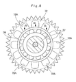
- the planetary gear 72 in this case is provided with a plurality of oil reservoirs 72A formed in an axial one-side end surface axially opposing the opposing surface portion 74E to be described later. As shown in Fig. 8 , each of the oil reservoirs 72A radially extends from an inner diameter side to an outer diameter side of the planetary gear 72 and is configured of a U-letter-shaped recessed groove.
- the lubricant oil is temporarily reserved in these oil reservoirs 72A as described later.
- the lubricant oil drops down in the direction of an arrow B in Fig. 8 by a gravity function and is supplied to the planetary gear bearing 39 when the planetary gear 72 rotates through the planetary gear bearing 39 around the support pin 37.
- the lubricant oil reserved in each of the oil reservoirs 72A spreads out due to a function of a centrifugal force, and the droplet lubricant oil drops down to the planetary gear bearing 39 for substantial oil supply.
- Denoted at 73 is a carrier adopted in the third embodiment, and the carrier 73 is configured substantially in the same way with the carrier 38 described in the first embodiment, and includes annular support plates 73A and 73B, a plurality of pin mounting hole portions 73C and 73D, a plurality of connecting portions 73E and female splines 73F.
- the carrier 73 in this case differs from that in the first embodiment in a point where a plurality of oil guide groove portions 73G are formed in an end surface of the support plate 73A axially opposing the oil reservoir 72A of the planetary gear 72.
- Each of the oil guide groove portions 73G is arranged in a position substantially in agreement with each of the oil guide groove portions 74F of the cylindrical coupling member 74 to be described later, and is configured of a radial groove extending to a radial outside around the rotational shaft 17, for example.
- Each of the oil guide groove portions 73G is arranged in such a position that an end portion of the radial outside axially opposes the planetary gear bearing 39.
- each of the oil guide groove portions 73G radially extends from a side of the opposing surface portion 74E of the cylindrical coupling member 74 to a side of the each of the support pins 37, and guides a part of lubricant oil ejected from the meshing part 40 between the sun gear 71 and each of the planetary gears 72, in between each of the planetary gears 72 and each of the support pins 37.
- the cylindrical coupling member 74 is the cylindrical coupling member removably provided between the opening side of the spindle 14 and the carrier 73, and the cylindrical coupling member 74 is configured substantially in the same way with the cylindrical coupling member 53 described in the first embodiment.
- the cylindrical coupling member 74 includes first male spline (not shown), second male spline 74B, an annular step portion (not shown), a stepped hole 74D, and an opposing surface portion 74E. That is, the opposing surface portion 74E of the cylindrical coupling member 74 opposes the meshing part 40 between the sun gear 71 and each of the planetary gears 72 through the axial gap 54.
- the opposing surface portion 74E of the cylindrical coupling member 74 is provided with a plurality of oil guide groove portions 74F formed to radially extend from the inner diameter side to the oil guide groove portion 73G of the carrier 73.
- Each of the oil guide groove portions 74F of the cylindrical coupling member 74 and each of the oil guide groove portions 73G of the carrier 73 form part of an oil reservoir for guiding a part of lubricant oil ejected in the direction of an arrow A (refer to Fig. 7 ) from the meshing part 40 between the sun gear 71 and each of the planetary gears 72 to the planetary gear bearing 39 between each of the planetary gears 72 and each of the support pins 37, and for temporarily reserving the lubricant oil.
- the opposing surface portion 74E of the cylindrical coupling member 74 is provided with a dam up portion 74G positioned in a radial inside of each of the oil guide groove portions 74F for damming flow of an oil liquid.
- the dam up portion 74G functions to suppress the lubricant oil in each of the oil guide groove portions 74F to flow into the stepped hole 74D of the cylindrical coupling member 74 by narrowing the gap 54.
- Each of the oil guide groove portions 74F is configured such that a radial inside section thereof is closed by the dam up portion 74G and a radial outside section thereof is opened to each of the oil guide groove portions 73G of the carrier 73.
- Denoted at 75 is an oil guide path adopted in the third embodiment, and the oil guide path 75 is formed between a one-side end surface of each of the planetary gears 72 and the opposing surface portion 74E of the cylindrical coupling member 74 in the same way with the oil guide path 55 described in the first embodiment.
- the oil guide path 75 guides lubricant oil ejected in the direction of an arrow A (refer to Fig. 7 ) from the meshing part 40 between the sun gear 71 and each of the planetary gears 72 to the planetary gear bearing 39 between the planetary gear 72 and the support pin 37, maintaining the planetary gear bearing 39 to be in an oil supplied state.
- the oil guide path 75 is constituted by each of the oil reservoirs 72A in the planetary gear 72, each of the oil guide groove portions 73G in the carrier 73, and the opposing surface portion 74E, each of the oil guide groove portions 74F and the dam up portion 74G in the cylindrical coupling member 74.
- the oil guide path 75 can guide the lubricant oil axially ejected from the meshing part 40 between the sun gear 71 and each of the planetary gears 72 to the planetary gear bearing 39 between the planetary gear 72 and the support pin 37. Therefore, the third embodiment can obtain the operational effect substantially similar to that of the first embodiment.
- the plurality of the oil guide groove portions 73G radially extending are provided in the support plate 73A of the carrier 73, and the plurality of the oil guide groove portions 74F radially extending are provided also in the opposing surface portion 74E of the cylindrical coupling member 74.
- These oil guide groove portions 73G and 74F are arranged in positions to be communicated with each other.
- the lubricant oil ejected from the meshing part 40 between the sun gear 71 and each of the planetary gears 72 can be guided between each of the planetary gears 72 and each of the support pins 37 along each of the oil guide groove portions 73G and 74F to maintain the planetary gear bearing 39 therebetween to be in a lubricating state.
- the plurality of the oil reservoirs 72A formed in the end surface of each of the planetary gears 72 can trap and temporarily reserve therein the lubricant oil ejected from the meshing part 40 between the sun gear 71 and each of the planetary gears 72 through the opposing surface portion 74E of the cylindrical coupling member 74, each of the oil guide groove portions 74F, and the like.
- the oil reservoirs 72A can supply the lubricant oil to the planetary gear bearing 39 between the planetary gear 72 and the support pin 37 with rotation of the planetary gear 72.
- the annular step portion 36A is provided in the planetary gear 36 as an example.
- the present invention is not limited thereto, and, for example, as the planetary gear 72 described in the third embodiment, the plurality of the oil reservoirs 72A may be formed therein.
- the lubricant oil is only required to be capable of being supplied between the planetary gear and the support pin, and the planetary gear without the annular step portion 36A or the oil reservoir 72A may be used.
- the cylindrical coupling member 53 is provided with the male splines 53A and 53B, and the spindle 14 and the carrier 38 are spline-coupled, as an example.
- the present invention is not limited thereto, and, for example, the spindle and the cylindrical coupling member may be coupled by rotation-preventive means such as a key.
- the same method can be applied between the carrier and the cylindrical coupling member. In this regard, the same method can be applied to the second and third embodiments.
- the reduction gear mechanism 24 is configured by the second-stage planetary gear reduction mechanisms 25 and 33, as an example.
- the present invention is not limited thereto, and for example, the reduction gear mechanism may be configured by a first, third or more-stage planetary gear reduction mechanisms.
- each of the aforementioned embodiments is explained by taking the dump truck 1 of a rear-wheel drive type as an example.
- the present invention is not limited thereto, and the present invention may be applied to a dump truck of a front-wheel drive type or a four-wheel drive type driving front and rear wheels together.
- Features, components and specific details of the structures of the above-described embodiments may be exchanged or combined to form further embodiments optimized for the respective application. As far as those modifications are apparent for an expert skilled in the art they shall be disclosed implicitly by the above description without specifying explicitly every possible combination.
Abstract
Description
- The present invention relates to a travel drive device for a dump truck which is suitably used in transporting crushed stones excavated from such as an open-pit stope, a stone quarry or a mine.
- In general, a large-sized transporter vehicle called a dump truck has a liftable vessel (loading platform) on a frame of a vehicle body, and transports crushed stones or the like in a state of the heavy baggage such as crushed stones being loaded in a large quantity on the vessel.
- Therefore, each travel drive device for driving drive wheels of the dump truck for traveling is provided with an axle housing mounted in a non-rotating state on a vehicle body and having a tip end side opened to form a cylindrical spindle, a rotational shaft provided to axially extend in the spindle of the axle housing and driven and rotated by a drive source, a wheel mounting cylinder which is rotatably mounted on an outer peripheral side of the spindle through wheel support bearings and to which vehicle wheels are mounted, a reduction gear mechanism provided between the wheel mounting cylinder and the spindle to decelerate rotation of the rotational shaft, which is transmitted to the wheel mounting cylinder, and lubricant oil accommodated in a bottom side of the wheel mounting cylinder in a state of being reserved therein to lubricate the reduction gear mechanism (
Patent Documents 1 and 2). - The reduction gear mechanism is constituted by a multi-stage planetary gear reduction mechanism comprising a sun gear arranged on an outer peripheral side of the rotational shaft and rotating with rotation of the rotational shaft, a plurality of planetary gears meshing with the sun gear and a ring-shaped internal gear, and a carrier rotatably supporting the respective planetary gears through support pins. The carrier forming a part of a final-stage planetary gear reduction mechanism is configured to be mounted in a non-rotating state on an open end side of the spindle.
-
- Patent Document 1: Japanese Patent Laid-Open No.
2009-204216 A - Patent Document 2: Japanese Patent Laid-Open No.
2010-116963 A - Incidentally, according to the travel drive device for the dump truck according to the aforementioned conventional art, since the carrier used for the final-stage planetary gear reduction mechanism is mounted in a non-rotating state on the open end side of the spindle, the carrier and the spindle are coupled by a spline-coupling portion formed of a male spline and a female spline. However, this spline-coupling portion does not necessarily have sufficient strength in a case where a loading weight of the dump truck is increased to, for example, 250 tons or more, and a further improvement on the coupling portion is needed.
- In addition, since rotation of the carrier is restrained by the spindle in the final-stage planetary gear reduction mechanism, at least a part of a plurality of planetary gears supported by this carrier repeats the rotation in a state of being exposed from an oil surface of the lubricant oil. Therefore, it is difficult to supply a sufficient amount of the lubricant oil to a support pin and a planetary gear bearing rotatably (rotatably on its axis) supporting the planetary gear, creating a problem with possible occurrence of lubrication lack.
- In view of the above-discussed problem with the conventional art, it is an object of the present invention to provide a travel drive device for a dump truck which can enhance the strength to a rotational load by providing a separate coupling member between an open end side of a spindle and a carrier to improve durability and lifetime of an entire device.
- Further, another object of the present invention is to provide a travel drive device for dump truck which can guide lubricant oil between a planetary gear performing only a rotational movement without performing a revolving movement and a support pin to maintain a lubricating state between the planetary gear and the support pin, thus enhancing durability and reliability of an entire device.
- (1) In order to solve the aforementioned problem, the present invention is applied to a travel drive device for a dump truck comprising an axle housing mounted in a non-rotating state on a vehicle body of a dump truck and having an end side opened to form a cylindrical spindle; a rotational shaft provided to axially extend in the spindle of the axle housing and driven and rotated by a drive source; a wheel mounting cylinder which is rotatably provided on an outer peripheral side of the spindle through wheel support bearings and to which wheels are mounted; a planetary gear reduction mechanism provided between the wheel mounting cylinder and the spindle to decelerate rotation of the rotational shaft, which is transmitted to the wheel mounting cylinder; and/or lubricant oil accommodated in a bottom side of the wheel mounting cylinder in a state of being reserved therein to lubricate the planetary gear reduction mechanism, the planetary gear reduction mechanism comprising a sun gear arranged on an outer peripheral side of the rotational shaft and rotating with rotation of the rotational shaft; a plurality of planetary gears meshing with the sun gear for rotation; and/or a carrier rotatably supporting each of the plurality of the planetary gears through a support pin, wherein the carrier is mounted in a non-rotating state on an open end side of the spindle.
- A characteristic of a construction adopted by the present invention lies in that a cylindrical coupling member which is formed as a coupling member for connecting the spindle and the carrier is provided between the spindle and the carrier and the rotational shaft is inserted in an inner peripheral side of the cylindrical coupling member, the cylindrical coupling member is provided with an opposing surface portion positioned higher than a liquid surface level of the lubricant oil and opposing through an axial gap a meshing part between the sun gear and each of the planetary gears, and an oil guide path is formed between each of the planetary gears and the opposing surface portion and guides the lubricant oil ejected from the meshing part between the sun gear and each of the planetary gears in between each of the planetary gears and each of the support pins.
- With this arrangement, the spindle and the carrier can be connected in a non-rotating state by using the cylindrical coupling member made up of the single, independent member, increasing the strength to the rotational load, as well as improving durability and lifetime of an entire travel drive device. On the other hand, by restraining the rotation of the carrier, the lubricant oil axially ejected from the meshing part between the sun gear and each of the planetary gears can be guided through the oil guide path between the support pin and the planetary gear repeatedly performing only the rotational movement without performing the revolving movement. Therefore, the lubricating state can be maintained between the planetary gear and the support pin to enhance the durability and the reliability of the entire device.
- Namely, the cylindrical coupling member has the opposing surface portion opposing the meshing part between the sun gear and each of the planetary gears through the axial gap. Therefore, the lubricant oil ejected from the meshing part between the sun gear and each of the planetary gears can be trapped in the oil guide path between the opposing surface portion of the cylindrical coupling member and the end surface of each of the planetary gears to be guided between the planetary gear and the support pin. As a result, the planetary gear bearing provided between the planetary gear and the support pin can be maintained in a lubricating state.
- (2) According to the present invention, the sun gear is configured such that an axial one-side end surface projects closer to an axial one side of the opposing surface portion of the cylindrical coupling member than an end surface of each of the planetary gears to be close to the opposing surface portion of the cylindrical coupling member to narrow the gap.
- With this arrangement, since the end surface of the sun gear in the axial one side is close to the opposing surface portion of the cylindrical coupling member, the gap formed between them can be narrowed. Therefore, the lubricant oil ejected from the meshing part between the sun gear and each of the planetary gears can be trapped in the oil guide path to be guided between the planetary gear and the support pin. As a result, the planetary gear bearing provided between the planetary gear and the support pin can be maintained in a lubricating state.
- (3) According to the present invention, each of the planetary gears is provided with an annular step portion extending over an entire circumference between an outer diameter side section meshing with the sun gear and an inner diameter side section supported through a planetary gear bearing by the support pin, wherein the annular step portion forms a part of the oil guide path for guiding the lubricant oil ejected from the meshing part between the sun gear and each of the planetary gears in between each of the planetary gears and each of the support pins.
- With this arrangement, the annular step portion provided in each of the planetary gears can efficiently trap the lubricant oil ejected from the meshing part between the sun gear and each of the planetary gears. The trapped lubricant oil can be guided between the planetary gear and the support pin with rotation (rotation on its axis) of the planetary gear.
- (4) According to the present invention, each of the planetary gears is provided with a plurality of oil reservoirs formed in a one-side end surface axially opposing the opposing surface portion of the cylindrical coupling member, wherein each of the oil reservoirs temporarily reserves the lubricant oil ejected from the meshing part between the sun gear and each of the planetary gears therein to form a part of the oil guide path.
- With this arrangement, each of the plurality of the oil reservoirs formed in the end surface of each of the planetary gears can trap and temporarily reserve therein the lubricant oil ejected from the meshing part between the sun gear and each of the planetary gears. The lubricant oil can be guided between the planetary gear and the support pin with rotation (rotation on its axis) of the planetary gear.
- (5) According to the present invention, the opposing surface portion of the cylindrical coupling member is provided with a guide projection for beating off the lubricant oil ejected from the meshing part between the sun gear and each of the planetary gears toward a radial outside.
- With this arrangement, the guide projection provided in the opposing surface portion of the cylindrical coupling member can beat off the lubricant oil ejected from the meshing part between the sun gear and each of the planetary gears toward the radial outside. The lubricating state can be maintained in the planetary gear bearing between the planetary gear and the support pin by guiding the beat lubricant oil in between each of the planetary gears and the support pin.
- (6) According to the present invention, the opposing surface portion of the cylindrical coupling member is provided with a plurality of oil guide groove portions radially extending from an inner peripheral side of the opposing surface portion toward the carrier to guide the lubricant oil ejected from the meshing part between the sun gear and each of the planetary gears in between each of the planetary gears and each of the support pins.
- With this arrangement, the plurality of the oil guide groove portions provided in the opposing surface portion of the cylindrical coupling member radially extend from the inner peripheral side to the carrier side. Therefore, the lubricant oil ejected from the meshing part between the sun gear and each of the planetary gears can be guided in between each of the planetary gears and each of the support pins to maintain the planetary gear bearing to be in a lubricating state.
- (7) According to the present invention, a surface of the carrier opposing the planetary gear is provided with a plurality of oil guide groove portions radially extending from a side of the opposing surface portion of the cylindrical coupling member to a side of each of the support pins to guide the lubricant oil ejected from the meshing part between the sun gear and each of the planetary gears in between each of the planetary gears and each of the support pins.
- With this arrangement, the plurality of the oil guide groove portions provided on the surface of the carrier opposing the planetary gear radially extend from the side of the opposing surface portion of the cylindrical coupling member to the side of each of the support pins. Therefore, the lubricant oil ejected from the meshing part between the sun gear and each of the planetary gears can be guided in between each of the planetary gears and each of the support pins to maintain the planetary gear bearing to be in a lubricating state.
-
-
Fig. 1 is a side view showing a dump truck to which a travel drive device according to a first embodiment of the present invention is applied. -
Fig. 2 is a rear view showing the dump truck inFig. 1 as viewed from the backside. -
Fig. 3 is an enlarged cross section showing the travel drive device in the rear wheel side, as viewed in the direction of arrows III-III inFig. 1 . -
Fig. 4 is an enlarged cross section showing a planetary gear reduction mechanism, a wheel mounting cylinder and an open side of a spindle inFig. 3 . -
Fig. 5 is a further enlarged cross section showing an oil guide path provided among a sun gear, a planetary gear, and a cylindrical coupling member inFig. 4 . -
Fig. 6 is a further enlarged cross section showing an oil guide path provided among a sun gear, a planetary gear, and a cylindrical coupling member according to a second embodiment. -
Fig. 7 is a further enlarged cross section showing an oil guide path provided among a sun gear, a planetary gear, and a cylindrical coupling member according to a third embodiment. -
Fig. 8 is an enlarged cross section showing the planetary gear, a support pin, and a planetary gear bearing as viewed in the direction of arrows VIII - VIII inFig. 7 . - Hereinafter, a travel drive device for a dump truck according to embodiments of the present invention will be in detail explained with reference to the accompanying drawings by taking a dump truck of a rear-wheel drive type as an example.
-
Fig. 1 to Fig. 5 show a travel drive device for a dump truck according to a first embodiment in the present invention. - In the figure, designated at 1 is a dump truck of a large-sized transporter vehicle adopted in the first embodiment. The
dump truck 1 is constituted by including avehicle body 2 having a strong frame structure and avessel 3 as a loading platform liftably mounted on thevehicle body 2. - The
vessel 3 is formed, for example, as a large-sized container of an entire length of 9 to 13 meters for loading a large volume of heavy baggage such as crushed stones. A rear-side bottom portion of thevessel 3 is liftably (tiltably) connected to a rear end side of thevehicle body 2 through a connectingpin 4. Aprotector 3A is integrally provided in a front-side top portion of thevessel 3 in such a manner as to cover a cab 5 to be described later from the upper side. - The cab 5 is provided in the front portion of the
vehicle body 2 to be positioned under theprotector 3A. The cab 5 forms an operator's room which an operator of thedump truck 1 gets in and off. An operator's seat, an activation switch, an accelerator pedal, a brake pedal, a handle for steering, and a plurality of operating levers (any of them is not shown) are provided inside the operator's room. Theprotector 3A of thevessel 3 has functions of protecting the cab 5 from flying stones such as rocks by substantially completely covering the cab 5 from the upper side, and protecting an operator inside the cab 5 at the falling-down of a vehicle (dump truck 1). - Left and right
front wheels 6 are rotatably provided on the front side of thevehicle body 2. Eachfront wheel 6 forms a steered wheel which is steered by an operator of thedump truck 1. Further, thefront wheel 6 is formed in a tire diameter (outer diameter dimension), for example, as long as 3 to 4 meters in the same way as each ofrear wheels 7 to be described later. A front-wheel side suspension 6SP formed by a hydraulic shock absorber is provided between the front portion of thevehicle body 2 and thefront wheel 6. - The left and right
rear wheels 7 are rotatably provided on the rear side of thevehicle body 2. Eachrear wheel 7 forms a drive wheel of thedump truck 1 which is driven and rotated integrally with awheel mounting cylinder 18 by atravel drive device 11 to be described later as shown inFig. 3 . Eachrear wheel 7 is constituted by including dual tires of aninner tire 7A and anouter tire 7A, andrims 7B disposed in a radial inside of therespective tires 7A. A rear-wheel side suspension 7SP formed by a hydraulic shock absorber is provided between the rear portion of thevehicle body 2 and therear wheel 7. - An
engine 8 is provided in thevehicle body 2 to be positioned under the cab 5. Theengine 8 is constituted by, for example, a large-sized diesel engine and drives an on-board power generator and a hydraulic pump as a hydraulic source (any thereof is not shown) for rotation. Pressurized oil discharged from the hydraulic pump is supplied to hoistcylinders 9, a steering cylinder for power steering (not shown) and the like to be described later. - The hoist
cylinder 9 is a cylinder apparatus for lifting thevessel 3. The hoistcylinder 9 is positioned between thefront wheel 6 and therear wheel 7 to be disposed in each of both left and right sides of thevehicle body 2. Each of the hoistcylinders 9 is mounted between thevehicle body 2 and thevessel 3 to telescopically operate in the upper-lower direction. Each of the hoistcylinders 9 expands and contracts in the upper-lower direction by supply/discharge of the pressurized oil from/to the hydraulic pump to lift (tilt) thevessel 3 around the connectingpin 4 of the rear side. - As shown in
Fig. 1 , an operatingoil tank 10 is mounted to a side of thevehicle body 2 or the like to be positioned under thevessel 3. Operating oil accommodated in the operatingoil tank 10 is suctioned by the hydraulic pump and discharged therefrom to be pressurized, which is supplied/discharged to/from the hoistcylinder 9, the steering cylinder for power steering, and the like. - Next, an explanation will be made of the
travel drive device 11 which is provided to the side of therear wheel 7 in thedump truck 1 and forms a key part of the first embodiment. - The
travel drive device 11 is constituted by including anaxle housing 12, awheel drive motor 16, awheel mounting cylinder 18 and areduction gear mechanism 24, which will be described later. Thetravel drive device 11 decelerates rotation of thewheel drive motor 16 by thereduction gear mechanism 24 and drives therear wheels 7 as drive wheels of a vehicle together with thewheel mounting cylinder 18 by large rotational torque. - Designated at 12 is the axle housing for the
rear wheel 7, which is provided under the rear side of thevehicle body 2, and theaxle housing 12 is formed in a cylindrical body which axially extends between the left and rightrear wheels 7. Theaxle housing 12 is constituted by an intermediatecylindrical body 13 mounted to the rear side of thevehicle body 2 through the rear-wheel side suspension 7SP and aspindle 14 mounted to each of both left and right sides of thecylindrical body 13, which will be described later. - The
spindles 14 are provided respectively at axial both sides of theaxle housing 12 and eachspindle 14 is formed in a cylindrical body. As shown inFig. 3 , thespindle 14 is constituted by including a large-diametercylindrical portion 14A positioned at an axial one side, formed to be tapered and removably fixed to thecylindrical body 13 throughbolts 15, and a circularcylindrical portion 14B which is formed integrally with the large-diametercylindrical portion 14A at an axial other side and a tip end side of which is opened. The circularcylindrical portion 14B is arranged to axially extend within thewheel mounting cylinder 18 to be described later. An outer peripheral side of the circularcylindrical portion 14B rotatably supports thewheel mounting cylinder 18 in the side of therear wheel 7 throughwheel support bearings - Here, the
spindle 14 has an outer peripheral side formed integrally with anannular flange portion 14C which radially outwardly projects from an intermediate section of the large-diametercylindrical portion 14A in a length direction (axially) and to which awet brake 47 is mounted, and with anannular step portion 14D provided to the circularcylindrical portion 14B at an axial one side for axially positioning a one-side retainer 50. A plurality ofmotor mounting seats 14E are formed integrally to the large-diametercylindrical portion 14A at one side in an axial direction to radially inwardly project therefrom, andwheel drive motors 16 to be described later are mounted to themotor mounting seats 14E. - On the other hand, an axial other side (tip end side) of the circular
cylindrical portion 14B is formed as an open end, and an inner peripheral side thereof is provided with afemale spline 14F (refer toFig. 4 ) formed thereon. Thefemale spline 14F is spline-coupled to afirst male spline 53A of acylindrical coupling member 53 to be described later. In regard to themale spline 53A, each tooth flank is subjected to a modification process (for example, a crowning process). Thereby, thefemale spline 14F can make a tooth contact of each tooth face with thefirst male spline 53A uniform. - A circular inward projecting
portion 14G is formed integrally on an inner peripheral side of the circularcylindrical portion 14B at an axial intermediate section, and a bearingretainer 45 to be described later is mounted to the inward projectingportion 14G through bolts. Aradial hole 14H is formed in the lower part of the circularcylindrical portion 14B to penetrate and extend therethrough from an inner diameter side to an outer diameter side of the circularcylindrical portion 14B (radial direction of the circularcylindrical portion 14B), and asuction pipe 42 to be described later is inserted into theradial hole 14H. - The
wheel drive motor 16 is removably mounted in theaxle housing 12, and thewheel drive motor 16 is used as a drive source of therear wheel 7. Thewheel drive motor 16 is formed of a large-sized electric motor driven and rotated by power supply from a power generator (not shown) mounted on thevehicle body 2. As shown inFig. 2 , each of thewheel drive motors 16 is mounted within thespindle 14 to be position in each of left and right sides of thecylindrical body 13 to drive and rotate the left and rightrear wheels wheel drive motor 16 is provided at an outer peripheral side with a plurality of mountingflanges 16A which are removably mounted to themotor mounting seat 14E of thespindle 14 by using bolts. Thewheel drive motor 16 is configured to drive and rotate arotational shaft 17 by supplying power from the power generator. - The
rotational shaft 17 is configured as an output shaft of thewheel drive motor 16 and is driven and rotated in the forward or backward direction by thewheel drive motor 16. Therotational shaft 17 is formed of a single, elongated, bar-shaped body extending in an axial direction (left and right directions) at the inner peripheral side of thespindle 14, and one end side of therotational shaft 17 is connected to an output side of thewheel drive motor 16. On the other hand, the other end side of therotational shaft 17 projects from an open end side of the circularcylindrical portion 14B forming thespindle 14 and to a projecting end of which asun gear 26 to be described later is mounted. An axial intermediate section of therotational shaft 17 is positioned between thewheel support bearings spindle 14 by using a rotational shaft bearing 46 to be described later. - Denoted at 18 is the wheel mounting cylinder rotating integrally with the
rear wheel 7 as a wheel. Thewheel mounting cylinder 18 forms a so-called wheel hub, and has the outer peripheral side to which eachrim 7B of therear wheel 7 is removably mounted by means such as press-fitting. Thewheel mounting cylinder 18 is integrally formed of a hollowcylindrical portion 18A axially extending between thewheel support bearings cylindrical portion 18B axially extending from an outer peripheral end portion of the hollowcylindrical portion 18A toward aninternal gear 35 to be described later. Accordingly, thewheel mounting cylinder 18 is formed as an integral object in a stepped cylindrical shape as a whole. - The
internal gear 35 and anouter drum 22 to be described later are integrally fixed to the extendingcylindrical portion 18B of thewheel mounting cylinder 18 by usinglong bolts 23. Therefore, thewheel mounting cylinder 18 is rotated integrally with theinternal gear 35. That is, rotation of large torque obtained by decelerating the rotation of thewheel drive motor 16 with thereduction gear mechanism 24 is transmitted to thewheel mounting cylinder 18 through theinternal gear 35. Therefore, thewheel mounting cylinder 18 rotates therear wheel 7 as the drive wheel in a vehicle with the large rotational torque. - A
rim spacer 19 is formed by a cylindrical ring. Therim spacer 19 is arranged at the outer peripheral side of thewheel mounting cylinder 18 to ensure a predetermined axial gap between aninner tire 7A and anouter tire 7A in therear wheel 7. That is, as shown inFig. 3 , therim spacer 19 is sandwiched tightly between arim 7B in an axial inside and arim 7B in an axial outside of therear wheel 7 to keep a space therebetween to be axially constant. - Denoted at 20 and 21 are the wheel support bearings for rotatably supporting the
wheel mounting cylinder 18 on the outer peripheral side of thespindle 14 and thewheel support bearings wheel support bearings cylindrical portion 14B of thespindle 14 and the hollowcylindrical portion 18A of thewheel mounting cylinder 18. That is, the one wheel support bearing 20 is positioned to theannular step portion 14D of thespindle 14 through the one-side retainer 50 to be described later and the other wheel support bearing 21 is positioned to an open end-side outer periphery of the circularcylindrical portion 14B through anend retainer 51 to be described later. - Each inner race of the
wheel support bearings retainers cylindrical portion 14B of thespindle 14. Each outer race of thewheel support bearings cylindrical portion 18A of thewheel mounting cylinder 18. Therefore, thewheel mounting cylinder 18 is axially positioned to thespindle 14 by using thewheel support bearings retainers spindle 14 to be rotatable in a circumferential direction thereto. - The
outer drum 22 forms a part of thewheel mounting cylinder 18 together with theinternal gear 35. As shown inFig. 3 , theouter drum 22 is mounted in a position at an axial outside of thewheel mounting cylinder 18 to sandwich theinternal gear 35 to be described later therebetween and is removably fixed to thewheel mounting cylinder 18 by using a plurality oflong bolts 23. - Next, an explanation will be made of the
reduction gear mechanism 24 provided between thespindle 14 and thewheel mounting cylinder 18. - The
reduction gear mechanism 24 is constituted by a first-stage planetarygear reduction mechanism 25 and a final-stage planetarygear reduction mechanism 33 as a second stage, which will be described later. Thereduction gear mechanism 24 decelerates rotation of the wheel drive motor 16 (that is, rotational shaft 17), which is transmitted to thewheel mounting cylinder 18 at the side of therear wheel 7. Therefore, thewheel mounting cylinder 18 at the side of therear wheel 7 is driven and rotated together with therear wheel 7 by a large rotational force (torque) obtained by the deceleration. - Denoted at 25 is the first-stage planetary gear reduction mechanism forming the
reduction gear mechanism 24, and the first-stage planetarygear reduction mechanism 25 is constituted by thesun gear 26 spline-coupled to the tip end side as a free end of therotational shaft 17, a plurality (for example, three or four pieces) ofplanetary gears 28 meshed with thesun gear 26 and a ring-shapedinternal gear 27, and acarrier 30 rotatably supporting the respectiveplanetary gears 28 through support pins 29. - Here, the
carrier 30 is removably fixed at its outer peripheral side to an open end (an end surface at an axially outside) of theouter drum 22 integral with thewheel mounting cylinder 18 through bolts, and rotates integrally with thewheel mounting cylinder 18 and theouter drum 22. For example, a disk-shapedlid plate 31 is removably mounted to the inner peripheral side of thecarrier 30. Thelid plate 31 is removed from thecarrier 30, for example, at the time of inspection or maintenance of meshing parts between thesun gear 26 and the planetary gears 28. - The ring-shaped
internal gear 27 is formed by using a ring gear to surround thesun gear 26 and the respectiveplanetary gears 28 from a radial outside, and theinternal gear 27 is relatively rotatably located as having a radial gap to an inner peripheral surface of theouter drum 22. The rotation (revolving movement) of theinternal gear 27 is transmitted to a second-stage planetarygear reduction mechanism 33 through acoupling 32 to be described later. - As the
sun gear 26 is rotated integrally with therotational shaft 17 by thewheel drive motor 16, the first-stage planetarygear reduction mechanism 25 converts the rotation of thesun gear 26 into a rotating movement of each of theplanetary gears 28 and a revolving movement thereof. Further, the rotating movement (rotation) of each of theplanetary gears 28 is transmitted to the ring-shapedinternal gear 27 as a decelerated rotation. The rotation of theinternal gear 27 is transmitted to the second-stage planetarygear reduction mechanism 33 through thecoupling 32 to be described later. On the other hand, the revolving movement of each of theplanetary gears 28 is transmitted to theouter drum 22 in the side of thewheel mounting cylinder 18 by way of rotation of thecarrier 30. However, since thewheel mounting cylinder 18 rotates integrally with the second-stageinternal gear 35 to be described later, the revolving movement of each of theplanetary gears 28 is suppressed into rotation in synchronization with the internal gear 35 (the wheel mounting cylinder 18). - The
coupling 32 rotates integrally with the first-stageinternal gear 27, and thecoupling 32 is in the form of an annular rotation transmitting member which is located in a position between the first-stage planetarygear reduction mechanism 25 and the second-stage planetarygear reduction mechanism 33. That is, an outer peripheral side of thecoupling 32 is spline-coupled to the first-stageinternal gear 27. An inner peripheral side of thecoupling 32 is spline-coupled to a second-stage sun gear 34 to be described later. Thus, thecoupling 32 transmits rotation of the first-stageinternal gear 27 to the second-stage sun gear 34 to rotate thesun gear 34 integrally with the first-stageinternal gear 27. A plurality of oil holes may be formed in thecoupling 32 to circulatelubricant oil 100 to be described later in the front-rear direction (axial direction). - Denoted at 33 is the second-stage planetary gear reduction mechanism as a final stage, this planetary
gear reduction mechanism 33 is located between therotational shaft 17 and thewheel mounting cylinder 18 through the first-stage planetarygear reduction mechanism 25 and decelerates the rotation of therotational shaft 17 together with the first-stage planetarygear reduction mechanism 25. The second-stage planetarygear reduction mechanism 33 is constituted by thecylindrical sun gear 34 which is positioned on an outer peripheral side of therotational shaft 17 to be mounted coaxially with therotational shaft 17 and rotates integrally with thecoupling 32 according to rotation of therotational shaft 17, a plurality of planetary gears 36 (only one of which is shown in the figure) which are meshed with thesun gear 34 and the ring-shapedinternal gear 35, and acarrier 38 which rotatably supports the respectiveplanetary gears 36 through support pins 37. - A planetary gear bearing 39 is provided between an inner peripheral side of each of the
planetary gears 36 and each of the support pins 37, which is composed of, for example, two conical bearings backsides of which oppose to each other. The planetary gear bearing 39 supports theplanetary gear 36 together with thesupport pin 37 to be rotatable to thecarrier 38. Each of theplanetary gears 36 is provided with anannular step portion 36A extending over an entire circumference in the radial intermediate portion (that is, an intermediate portion between an outer diameter side section meshing with thesun gear 34 and an inner diameter side section supported through the planetary gear bearing 39 by the support pin 37). Theannular step portion 36A temporarily traps thelubricant oil 100 to be described later on the inner surface and forms a part of anoil guide path 55 to be described later. - As shown in
Fig. 5 , thesun gear 34 has anend surface 34A in the axial one-side projecting closer to a side of an opposingsurface portion 53E to be described later than theplanetary gear 36 to be arranged in a position close to the opposingsurface portion 53E. Therefore, thelubricant oil 100 axially (for example, in the direction of an arrow A inFig. 5 ) ejected from a meshingpart 40 between thesun gear 34 and theplanetary gear 36 does not escape to a side of a steppedhole 53D of thecylindrical coupling member 53, but is guided by theoil guide path 55 to be trapped or collected in theannular step portion 36A of theplanetary gear 36. - On the other hand, the second-stage
internal gear 35 is formed by using a ring gear to surround thesun gear 34 and the respectiveplanetary gears 36 from a radial outside. Theinternal gear 35 is integrally fixed between the extendingcylindrical portion 18B forming a part of thewheel mounting cylinder 18 and theouter drum 22 by using thelong bolts 23. Further, internal teeth formed over the entire periphery on the inner peripheral side of theinternal gear 35 are meshed with the respectiveplanetary gears 36. - As shown in
Fig. 4 andFig. 5 , the second-stage carrier 38 as a final stage is configured by includingannular support plates hole portions portions 38E. Theannular support plates hole portions planetary gears 36 between thesupport plates support pin 37 are mounted to be fitted in the pin mountinghole portions portions 38E are arranged to be spaced in the circumferential direction from each pin mountinghole portion annular support plates - The
female spline 38F is formed on an inner peripheral side of thesupport plate 38A in thecarrier 38. Thefemale spline 38F is spline-coupled tosecond male spline 53B of thecylindrical coupling member 53 to be described later. In thesecond male spline 53B, each tooth flank is subjected to a modification process (for example, crowning process). Thereby, a tooth contact in each tooth flank between thesecond male spline 53B and thefemale spline 38F can be made uniform over an entire tooth width. - The
support plate 38A in thecarrier 38 is provided with an annular projectingportion 38G in an inner peripheral side of an end surface as an axial other side (an end surface axially opposing the planetary gear bearing 39). The annular projectingportion 38G axially projects to a side of theannular step portion 36A of theplanetary gear 36 in the same way with an annular projectingportion 53F of thecylindrical coupling member 53 to be described later. Thefemale spline 38F in thecarrier 38 is also formed in a position of the annular projectingportion 38G. Therefore, a tooth width (axial length) of thefemale spline 38F is longer by an axial projection dimension of the annular projectingportion 38G. The annular projectingportions annular step portion 36A in theplanetary gear 36 to temporarily trap thelubricant oil 100 to be described later. - Here, in regard to the second-stage planetary
gear reduction mechanism 33, thecarrier 38 is spline-coupled through thecylindrical coupling member 53 to be described later to the circularcylindrical portion 14B of thespindle 14, thereby restraining revolving movements of the respective planetary gears 36 (rotation of the carrier 38). Therefore, as thesun gear 34 rotates integrally with thecoupling 32, the second-stage planetarygear reduction mechanism 33 converts the rotation of thesun gear 34 into rotation of each of the planetary gears 36. The rotation of each of theplanetary gears 36 is transmitted to the second-stageinternal gear 35, and theinternal gear 35 is decelerated for rotation. Therefore, the rotational torque of large output decelerated at the two-stage through the first and second-stage planetarygear reduction mechanisms wheel mounting cylinder 18 to which theinternal gear 35 is fixed. - Next, a lubricating system for lubricating the
reduction gear mechanism 24 will be explained. The lubricating system is constituted by including apartition wall 41, thesuction pipe 42, asupply pipe 43, aninner retainer 44, the bearingretainer 45, and therotational shaft bearing 46. - Here, the
lubricant oil 100 is accommodated in a bottom side of thewheel mounting cylinder 18 in a state of being reserved therein, and the respective planetarygear reduction mechanisms lubricant oil 100 is supplied all the time. In this case, an oil surface of thelubricant oil 100 is lower than, for example, the lowest section of the circularcylindrical portion 14B forming thespindle 14 and is set in a position where a lower side section of each of thewheel support bearings travel drive device 11, thelubricant oil 100 can be stirred by thewheel mounting cylinder 18 and the respective planetarygear reduction mechanisms lubricant oil 100 can be restricted to be small. - The
partition wall 41 is provided in thespindle 14. Thepartition wall 41 is formed of an annular plate and is removably fixed at its outer peripheral side to an inner peripheral side of the large-diametercylindrical portion 14A of thespindle 14 by using bolts. Here, thepartition wall 41 is configured to divide an inside of thespindle 14 into a motor accommodatingspace portion 41A positioned at its axial one side for accommodating thewheel drive motor 16 and acylindrical space portion 41B positioned at its axial other side for communicating with the inside of thewheel mounting cylinder 18 all the time. - The
suction pipe 42 collects thelubricant oil 100 reserved in thewheel mounting cylinder 18 and thesuction pipe 42 has one side in the length direction axially extending within thecylindrical body 13 of theaxle housing 12 to be connected to a suction side of a lubricating pump (not shown). An intermediate section of thesuction pipe 42 in the length direction axially extends within thespindle 14 toward the side of thewheel mounting cylinder 18. Atip end side 42A (the other side in the length direction) of thesuction pipe 42 is bent in an L-letter shape downward from a lower side of therotational shaft 17 to penetrate through theradial hole 14H of thespindle 14. Therefore, thesuction pipe 42 is immersed at thetip end side 42A in thelubricant oil 100 in thewheel mounting cylinder 18 to collect thelubricant oil 100 to the side of the lubricating pump. - The
supply pipe 43supplies lubricant oil 100 into thereduction gear mechanism 24. Thesupply pipe 43 is located above thesuction pipe 42 and therotational shaft 17 in thespindle 14, a tip end side 43A of which is inserted into thecylindrical coupling member 53 to be described later. One side (base end side) in the length direction of thesupply pipe 43 is connected to a discharge side of the lubricating pump. Thelubricant oil 100 discharged from the lubricating pump is supplied from a tip end side 43A (the other side in the length direction) of thesupply pipe 43 toward thecylindrical coupling member 53 to be described later, that is, toward the planetarygear reduction mechanisms - The
lubricant oil 100 reserved in a bottom side of thewheel mounting cylinder 18 is suctioned from atip end side 42A of thesuction pipe 42 by driving the lubricating pump, and thelubricant oil 100 suctioned by the lubricating pump is cooled by an oil cooler (not shown). The cooledlubricant oil 100 is thereafter supplied through thesupply pipe 43 to the planetarygear reduction mechanisms gear reduction mechanisms - Denoted at 44 is the inner retainer provided to fit into an axial intermediate section of the
rotational shaft 17, and denoted at 45 is an outer bearing retainer located at the outer peripheral side of theinner retainer 44 through therotational shaft bearing 46. Here, theinner retainer 44 is press-fitted at its inner peripheral side into the intermediate section of therotational shaft 17 to rotate integrally with therotational shaft 17. Theouter bearing retainer 45 is fixed to an inward projectingportion 14G of thespindle 14 by using a plurality of bolts (not shown). - The bearing
retainer 45 is formed as an annular ring body. An outerrace mounting portion 45A is mounted on an inner peripheral side of the bearingretainer 45 in a state of preventing the outer race of the rotational shaft bearing 46 from pulling out of the bearingretainer 45. A cylindrical projectingportion 45B is provided on an outer peripheral side of the bearingretainer 45 to project toward an end surface of thecylindrical coupling member 53 to be described later at an axial one side. The cylindrical projectingportion 45B forms a positioning projection for axially positioning thecylindrical coupling member 53 inside the circularcylindrical portion 14B of thespindle 14. - The bearing
retainer 45 is provided withinsert holes Fig. 4 ) oppose with each other. Thesupply pipe 43 is mounted to penetrate through theinsert hole 45C. Thesuction pipe 42 is mounted to penetrate through theinsert hole 45D. The bearingretainer 45 is provided with a radial notchedportion 45E in a position under theinsert hole 45D. Thesuction pipe 42 is inserted through the notchedportion 45E into theradial hole 14H of thespindle 14. - That is, as shown in
Fig. 3 and inFig. 4 , mid-sections of thesuction pipe 42 and thesupply pipe 43 extend to axially penetrate through the bearingretainer 45, so that thesuction pipe 42 and thesupply pipe 43 are positioned in thespindle 14 through the bearingretainer 45. A plurality of bolt through holes (not shown) are formed in the bearingretainer 45. The bearingretainer 45 is fixed to the inward projectingportion 14G of thespindle 14 by a plurality of bolts inserted into the bolt through holes. - The rotational shaft bearing 46 is located between the
inner retainer 44 in the side of therotational shaft 17 and the bearingretainer 45 in the side of thespindle 14. The rotational shaft bearing 46 rotatably supports the axial intermediate section of therotational shaft 17 through theinner retainer 44 and theouter bearing retainer 45 in the circularcylindrical portion 14B of thespindle 14. Therefore, the core swing in the axial intermediate section of the longrotational shaft 17 can be suppressed, and the longrotational shaft 17 can transmit stable rotation of therotational shaft 17 to the first-stage sun gear 26. - A
wet brake 47 applies braking forces to rotation of thewheel mounting cylinder 18, and thewet brake 47 is constituted by a hydraulic brake of a wet multi-plate type. Thewet brake 47 is provided through abrake hub 48 to be described later between thespindle 14 in theaxle housing 12 and thewheel mounting cylinder 18. Thewet brake 47 applies braking forces to thebrake hub 48 rotating together with thewheel mounting cylinder 18. - The
brake hub 48 forms a part of thewet brake 47 and rotates together with thewheel mounting cylinder 18. Thebrake hub 48 is formed as a cylindrical body axially extending between thespindle 14 and thewet brake 47. The axial other side of thebrake hub 48 is removably fixed to the hollowcylindrical portion 18A of thewheel mounting cylinder 18 by a plurality ofbolts 49. - The one-
side retainer 50 positions an inner race of the wheel support bearing 20 to the circularcylindrical portion 14B of thespindle 14. As shown inFig. 3 , the one-side retainer 50 is provided to be fitted into the outer peripheral surface of the circularcylindrical portion 14B. An axial one side of the one-side retainer 50 abuts against theannular step portion 14D of thespindle 14. Meanwhile, an axial other side of the one-side retainer 50 axially abuts against the inner race of thewheel support bearing 20. Therefore, in regard to the wheel support bearing 20, the outer race is axially positioned by the hollowcylindrical portion 18A of thewheel mounting cylinder 18 and the inner race is axially positioned by the one-side retainer 50. - The
end retainer 51 is mounted to an end opening side of thespindle 14 through a plurality ofbolts 52 and forms the other-side retainer. Theend retainer 51 is fixed to the circularcylindrical portion 14B of thespindle 14 and axially positions the inner race of the wheel support bearing 21 with the outer peripheral side of the circularcylindrical portion 14B. That is, in regard to the wheel support bearing 21, the outer race is axially positioned by the hollowcylindrical portion 18A of thewheel mounting cylinder 18 and the inner race is axially positioned by theend retainer 51. Thereby, thewheel mounting cylinder 18 is rotatably supported by thewheel support bearings side retainer 50 and theend retainer 51. - The
end retainer 51 is formed as an annular ring body. An inner peripheral side of theend retainer 51 is provided with a retainingportion 51A projecting inward in a radial direction in such a manner as to abut against astep portion 53C of thecylindrical coupling member 53 to be described later. The retainingportion 51A makes surface contact with theannular step portion 53C over the entire circumference for performing an operation of retaining thecylindrical coupling member 53 at the open side of thespindle 14. Here, a plurality of bolt through holes are bored in theend retainer 51. Theend retainer 51 is fixed to the circularcylindrical portion 14B of thespindle 14 by the plurality ofbolts 52 inserted into the bolt through holes. - Next, the
cylindrical coupling member 53 used in the first embodiment will be explained. - Namely, the
cylindrical coupling member 53 is removably provided between the open side of thespindle 14 and thecarrier 38. Thecylindrical coupling member 53 is formed as a stepped cylindrical body formed of a single, separate member independently of thespindle 14 and thecarrier 38, and therotational shaft 17 is inserted with a gap in the inner peripheral side of thecylindrical coupling member 53. In regard to thecylindrical coupling member 53, an outer periphery thereof at one side in an axial direction is spline-coupled to the open end inner peripheral side of thespindle 14 and an outer periphery thereof at the other side in the axial direction is spline-coupled to the inner peripheral side of thecarrier 38. - The
first male spline 53A positioned in an axial one side and spline-coupled to thefemale spline 14F of thespindle 14, thesecond male spline 53B positioned in an axial other side and formed in a diameter smaller than thefirst male spline 53A to be spline-coupled to thefemale spline 38F of thecarrier 38, and theannular step portion 53C positioned between the first and secondmale splines cylindrical coupling member 53. - A stepped
hole 53D is provided on an inner peripheral side of thecylindrical coupling member 53 to have a large diameter at an axial one side and a small diameter at the axial other side. Therotational shaft 17 and a tip end side 43A of thesupply pipe 43 are inserted into the steppedhole 53D. Thecylindrical coupling member 53 is arranged in a position all the time higher than a liquid surface level of thelubricant oil 100 accommodated in thewheel mounting cylinder 18. - An end surface of the
cylindrical coupling member 53 at an axial other side forms the opposingsurface portion 53E opposing the meshingpart 40 between thesun gear 34 and each of theplanetary gears 36 through thegap 54 to be described later. The opposingsurface portion 53E in thecylindrical coupling member 53 is provided with the annular projectingportion 53F positioned in an outer diameter side thereof to axially project to a side of theannular step portion 36A of theplanetary gear 36. Thesecond male spline 53B is also formed in a position of the annular projectingportion 53F. Thereby, thesecond male spline 53B is longer in a tooth width (axial length) by an axial projection dimension of the annular projectingportion 53F. Thefemale spline 38F in thecarrier 38 is also provided with the similarannular projecting portion 38G on the end surface of thesupport plate 38A. - Denoted at 54 is the axial gap formed between the opposing
surface portion 53E of thecylindrical coupling member 53 and theend surface 34A of thesun gear 34 at one side, and thegap 54 is formed to be narrower as compared to theoil guide path 55 to be described later. That is, thegap 54 forms a dam in such a manner that thelubricant oil 100 ejected from the meshingpart 40 between thesun gear 34 and each of theplanetary gears 36 flows toward theoil guide path 55, and prevents thelubricant oil 100 from escaping toward a side of the steppedhole 53D of the cylindrical coupling member 53 (toward a radial inside of the sun gear 34). - Denoted at 55 is the oil guide path adopted in the first embodiment, and is formed between a one-side end surface of each of the
planetary gears 36 and the opposingsurface portion 53E of thecylindrical coupling member 53. Theoil guide path 55 guides the lubricant oil ejected in the direction of an arrow A (refer toFig. 5 ) from the meshingpart 40 between thesun gear 34 and each of theplanetary gears 36, to the planetary gear bearing 39 between theplanetary gear 36 and thesupport pin 37, thus maintaining the planetary gear bearing 39 to be in an oil supplied state. Theoil guide path 55 is constituted by including theannular step portion 36A of theplanetary gear 36, the annular projectingportion 38G of thecarrier 38, and the opposingsurface portion 53E and the annular projectingportion 53F of thecylindrical coupling member 53. - The
travel drive device 11 for thedump truck 1 according to the first embodiment has the aforementioned configuration, and next, an operation thereof will be explained. - When an operator who gets in the cab 5 of the
dump truck 1 activates theengine 8, the hydraulic pump as a hydraulic source is driven and rotated, and electric power is generated by a power generator (any thereof is not shown). At the time thedump truck 1 is driven to travel, the electric power is supplied from the power generator to thewheel drive motor 16, and thereby thewheel drive motor 16 is activated to rotate therotational shaft 17. - The rotation of the
rotational shaft 17 is transmitted from thesun gear 26 of the first-stage planetarygear reduction mechanism 25 to the respectiveplanetary gears 28 in a state of being decelerated, and the rotation of each of theplanetary gears 28 is transmitted through theinternal gear 27 and thecoupling 32 to thesun gear 34 of the second-stage planetarygear reduction mechanism 33 in a state of being decelerated. In regard to the second-stage planetarygear reduction mechanism 33, the rotation of thesun gear 34 is transmitted to the respectiveplanetary gears 36 in a state of being decelerated. At this time, since thecarrier 38 supporting the respectiveplanetary gears 36 is spline-coupled to the circularcylindrical portion 14B of thespindle 14 by using the separatedcylindrical coupling member 53, the revolving movements of the respective planetary gears 36 (rotation of the carrier 38) are restricted. - As a result, each of the
planetary gears 36 only rotates around thesun gear 34, and rotation decelerated by the rotation of each of theplanetary gears 36 is transmitted to theinternal gear 35 fixed to thewheel mounting cylinder 18. Thereby, thewheel mounting cylinder 18 rotates with the rotational torque of large output decelerated by the two-stage through the first and second-stage planetarygear reduction mechanisms rear wheels 7 as the drive wheel can be rotated together with thewheel mounting cylinder 18 to drive thedump truck 1 for traveling. - The
rotational shaft 17 axially extending from thespindle 14 toward an inside of thewheel mounting cylinder 18 has an axial intermediate section rotatably supported through the rotational shaft bearing 46 by theinner retainer 44 and theouter bearing retainer 45. Therefore, when therotational shaft 17 rotates in high speeds, the radial torsion or the core swing of the axial intermediate section to be generated due to eccentricity of therotational shaft 17 can be suppressed at the position of the rotational shaft bearing 46 to enhance durability of therotational shaft 17. - At the operation of the
travel drive device 11, thelubricant oil 100 reserved in thewheel mounting cylinder 18 is stirred upwards in order by rotation of thewheel mounting cylinder 18, the respectiveplanetary gears gear reduction mechanisms lubricant oil 100 is supplied to meshing sections of the respective gears, thewheel support bearings cylindrical portion 14B of thespindle 14 and thewheel mounting cylinder 18. At this time, in the second planetarygear reduction mechanism 33, thelubricant oil 100 is supplied also to the meshingpart 40 between thesun gear 34 and each of the planetary gears 36 (refer toFig. 4 andFig. 5 ). Thereafter, thelubricant oil 100 drops downwards and is reserved in the bottom side of thewheel mounting cylinder 18. - The
lubricant oil 100 accommodated in the bottom side of thewheel mounting cylinder 18 is suctioned up from thetip end side 42A of thesuction pipe 42 by the lubricating pump. Thelubricant oil 100 is cooled by an oil cooler, and subsequently, is discharged to the side of thesupply pipe 43. Therefore, thelubricant oil 100 can be sequentially supplied from the tip end side 43A of thesupply pipe 43 toward the reduction gear mechanism 24 (namely, the first and second-stage planetarygear reduction mechanisms 25 and 33) in thewheel mounting cylinder 18. - On the other hand, in a case of decelerating a traveling speed of the
dump truck 1 in the middle of the traveling, in some cases thedump truck 1 can not be sufficiently decelerated simply by decelerating rotation of thewheel drive motor 16. In such a case, an operator of thedump truck 1 depresses the brake pedal to supply a brake pressure (pressurized oil) to thewet brake 47 composed of a hydraulic brake of a wet multi-plate type. Thereby, thewet brake 47 can apply braking forces to thebrake hub 48 rotating integrally with thewheel mounting cylinder 18. - Incidentally, the
travel drive device 11 for thedump truck 1 is structured such that thecarrier 38 used for the final-stage planetarygear reduction mechanism 33 is mounted in a non-rotating state on the open end side of thespindle 14, and therefore thecarrier 38 and thespindle 14 are coupled by a spline-coupling portion. However, this spline-coupling portion used in the conventional art does not necessarily have sufficient strength in a case where a loading weight of thedump truck 1 is increased to, for example, 250 tons or more, and a further improvement on the coupling portion is needed. - In addition, since rotation of the
carrier 38 is restrained by thespindle 14 in the final-stage planetarygear reduction mechanism 33. Thereby, at least a part of a plurality of planetary gears 36 (for example, two or more planetary gears 36) supported by thecarrier 38 repeats the rotation in a state of being exposed upward from a liquid surface of thelubricant oil 100. Therefore, there are some cases where a sufficient amount of the lubricant oil can not be necessarily supplied to thesupport pin 37 and the planetary gear bearing 39 rotatably (rotatably on its axis) supporting theplanetary gear 36, creating a problem with possible occurrence of lubrication lack. - Therefore, according to the first embodiment, the
cylindrical coupling member 53, which is formed as an independent, single coupling member, is provided between the open side of thespindle 14 and thecarrier 38, wherein thespindle 14 and thecarrier 38 are spline-coupled by thecylindrical coupling member 53. Further, theoil guide path 55 is formed between a one-side end surface of each of theplanetary gears 36 and the opposingsurface portion 53E of thecylindrical coupling member 53. Theoil guide path 55 guides the lubricant oil ejected in the direction of an arrow A (refer toFig. 5 ) from the meshingpart 40 between thesun gear 34 and each of theplanetary gears 36, to the planetary gear bearing 39 between theplanetary gear 36 and thesupport pin 37. - The
oil guide path 55 is constituted by including theannular step portion 36A formed in the radial intermediate section of theplanetary gear 36, the annular projectingportion 38G of thecarrier 38, and the opposingsurface portion 53E and the annular projectingportion 53F of thecylindrical coupling member 53. On the other hand, thenarrow gap 54 is formed between the opposingsurface portion 53E of thecylindrical coupling member 53 and thesun gear 34, and thegap 54 forms a dam in such a manner that thelubricant oil 100 ejected from the meshingpart 40 flows toward theoil guide path 55. - The
cylindrical coupling member 53 is formed as a stepped cylindrical body by a single member, an axial one side thereof is positioned by thecylindrical projecting portion 45B of the bearingretainer 45, and an axial other side thereof is positioned through theannular step portion 53C by theend retainer 51. On the other hand, thecylindrical coupling member 53 is supported in a non-rotating state such that thefirst male spline 53A is spline-coupled to thefemale spline 14F of thespindle 14 and thesecond male spline 53B is spline-coupled to thefemale spline 38F of thecarrier 38. - In the first embodiment, by configuring the
cylindrical coupling member 53 in this manner, it is not required to integrally provide the cylindrical projecting portion having the male spline on the outer peripheral side, which is different from the carrier used in the conventional art, and therefore it is possible to simplify the shape of thecarrier 38. In addition, since thecylindrical coupling member 53 is a member separated from thespindle 14 and thecarrier 38, thecylindrical coupling member 53 can be formed in a simple shape. Therefore, when themale splines cylindrical coupling member 53, a hob cutter process can be adopted. Further, in regard to themale splines - On the other hand, the bearing
retainer 45 supports the outer race of the rotational shaft bearing 46 on the inner peripheral side of thespindle 14, but is provided with a cylindrical projectingportion 45B projecting toward an end surface of thecylindrical coupling member 53 at an axial one side. The cylindrical projectingportion 45B abuts against the end surface of thecylindrical coupling member 53, and thereby thecylindrical coupling member 53 can be axially positioned in thespindle 14. - As a result, the
cylindrical coupling member 53 is structured such that the end surface at the axial one side (side of thefirst male spline 53A) abuts against the cylindrical projectingportion 45B of the bearingretainer 45 and theannular step portion 53C at the axial intermediate section abuts against the retainingportion 51A of theend retainer 51. In consequence, thecylindrical coupling member 53 can be sandwiched from the axial both sides between the cylindrical projectingportion 45B and the retainingportion 51A. Therefore, thecylindrical coupling member 53 is accurately positioned in a state where the axial intermediate section is stable to an open end of thespindle 14. - On the other hand, in regard to the planetary
gear reduction mechanism 33, the rotation of thecarrier 38 is restrained by thespindle 14, and thereby theplanetary gear 36 repeatedly performs only the rotation without performing the revolving movement. However, the lubricant oil ejected in the direction of an arrow A (refer toFig. 5 ) from the meshingpart 40 between thesun gear 34 and theplanetary gear 36 can be guided through the aforementionedoil guide path 55 to thesupport pin 37 and theplanetary gear bearing 39. Therefore, the lubricating state can be maintained in the planetary gear bearing 39 between theplanetary gear 36 and thesupport pin 37 to enhance the durability and the reliability of the entiretravel drive device 11. - In this case, the
cylindrical coupling member 53 has the opposingsurface portion 53E opposing the meshingpart 40 between thesun gear 34 and each of theplanetary gears 36 through theaxial gap 54. Therefore, thegap 54 dams the lubricant oil ejected from the meshingpart 40 between thesun gear 34 and each of theplanetary gears 36, and traps the lubricant oil in such a manner as to flow toward theoil guide path 55. Therefore, the lubricant oil can be guided between theplanetary gear 36 and thesupport pin 37. Accordingly, the planetary gear bearing 39 can be maintained in a lubricating state. - Particularly, the one-
side end surface 34A of thesun gear 34 in the planetarygear reduction mechanism 33 projects closer to the axial one side of thecylindrical coupling member 53 than the end surface of each of theplanetary gears 36 to be close to the opposingsurface portion 53E of thecylindrical coupling member 53, that is, to narrow thegap 54. Therefore, thegap 54 guides the lubricant oil ejected in the direction of an arrow A (refer toFig. 5 ) from the meshingpart 40 between thesun gear 34 and each of theplanetary gears 36 to theoil guide path 55, and theoil guide path 55 can supply the lubricant oil to the planetary gear bearing 39 between theplanetary gear 36 and thesupport pin 37. - In consequence, even in a case where ejection of the lubricant oil from the meshing
part 40 between thesun gear 34 and each of theplanetary gears 36 cannot be sufficiently obtained because of an influence of a traveling speed of thedump truck 1, an inclination of thevehicle body 2 or the like, theplanetary gear 36 can be maintained to be in a lubricating state. As a result, thelubricant oil 100 attached on the tooth flank of thesun gear 34 projecting from each of theplanetary gears 36 can be splashed to theplanetary gear 36 by a function of a centrifugal force generated by rotation of thesun gear 34 to stably maintain theplanetary gear 36 to be in a lubricating state without any influence of the travelling speed of thedump truck 1, the inclination of thevehicle body 2 or the like. - Further, the
annular step portion 36A provided in the radial intermediate section of each of theplanetary gears 36 can trap the lubricant oil ejected from the meshingpart 40 between thesun gear 34 and each of theplanetary gears 36 through the opposingsurface portion 53E and the annular projectingportion 53F of thecylindrical coupling member 53, and can guide the trapped lubricant oil to the planetary gear bearing 39 with rotation (rotation on its axis) of theplanetary gear 36. - Therefore, according to the first embodiment, the lubricant oil is guided between the
planetary gear 36 performing repetition of only rotation without performing the revolving movement and thesupport pin 37 in the planetarygear reduction mechanism 33, and thereby the planetary gear bearing 39 between theplanetary gear 36 and thesupport pin 37 can be maintained in a lubricating state to enhance durability and reliability of the entiretravel drive device 11. In addition, by providing thecylindrical coupling member 53 as a separate coupling member between the open end side of thespindle 14 and thecarrier 38, the strength to the rotational load can be increased to enhance durability and lifetime of the entire device. - Next,
Fig. 6 shows a second embodiment according to the present invention. The present embodiment comprises a guide projection provided in an opposing surface of a cylindrical coupling member for beating off lubricant oil to a radial outside. It should be noted that in the second embodiment, the component elements that are identical to those of the foregoing first embodiment will be simply denoted by the same reference numerals to avoid repetitions of similar explanations. - In the figure, denoted at 61 is a sun gear adopted in the second embodiment, and the
sun gear 61 is configured substantially in the same way with thesun gear 34 described in the first embodiment. An axial one-side end surface 61A of thesun gear 61 projects closer to an opposingsurface portion 62E to be described later than theplanetary gear 36. However, in regard to thesun gear 61 in this case, the projection dimension is made smaller than that of thesun gear 34 described in the first embodiment. That is, since aguide projection 62G is provided in acylindrical coupling member 62 to be described later, an axial entire length dimension (projection dimension) of thesun gear 61 is formed smaller by the projection dimension of theguide projection 62G. - Denoted at 62 is the cylindrical coupling member removably provided between the open side of the
spindle 14 and thecarrier 38. Thecylindrical coupling member 62 is configured substantially in the same way with thecylindrical coupling member 53 described in the first embodiment, and includes first male spline (not shown),second male spline 62B, an annular step portion (not shown), a steppedhole 62D, the opposingsurface portion 62E, and an annular projectingportion 62F. Namely, the opposingsurface portion 62E of thecylindrical coupling member 62 opposes the meshingpart 40 between thesun gear 61 and each of theplanetary gears 36 through theaxial gap 54, and the annular projectingportion 62F axially projecting toward a side of theannular step portion 36A of theplanetary gear 36 is provided in the outer diameter side of the opposingsurface portion 62E. - However, the
cylindrical coupling member 62 in this case differs from the first embodiment in a point where theguide projection 62G which projects toward an axial one-side end surface 61A of thesun gear 61 is formed in an inner diameter side of the opposingsurface portion 62E. Theguide projection 62G is configured of an annular projection extending over an entire circumference along the steppedhole 62D of thecylindrical coupling member 62, and is arranged in a position slightly closer to a radial inside than the meshingpart 40 between thesun gear 61 and each of the planetary gears 36. Theguide projection 62G beats off a part of the lubricant oil ejected in the direction of an arrow A (refer toFig. 6 ) from the meshingpart 40 between thesun gear 61 and each of theplanetary gears 36 toward a radial outside, and causes theannular step portion 36A of theplanetary gear 36 to trap and collect the beat lubricant oil, for example. - Further, the
guide projection 62G extending over an entire circumference of thecylindrical coupling member 62 is provided with one ormore notches 62H formed in a position lower than therotational shaft 17, for example. Thenotch 62H flows lubricant oil flown into the steppedhole 62D out of the lubricant oil ejected in the direction of an arrow A (refer toFig. 6 ) from the meshingpart 40 between thesun gear 61 and each of theplanetary gears 36, downwards from an inside of thecylindrical coupling member 62 for discharge. - Denoted at 63 is an oil guide path adopted in the second embodiment, and is formed between a one-side end surface of each of the
planetary gears 36 and the opposingsurface portion 62E of thecylindrical coupling member 62 in the same way with theoil guide path 55 described in the first embodiment. Theoil guide path 63 guides the lubricant oil ejected in the direction of an arrow A (refer toFig. 6 ) from the meshingpart 40 between thesun gear 61 and each of theplanetary gears 36 to the planetary gear bearing 39 between theplanetary gear 36 and thesupport pin 37, maintaining the planetary gear bearing 39 to be in an oil supplied state. Theoil guide path 63 is constituted by theannular step portion 36A of theplanetary gear 36, the annular projectingportion 38G of thecarrier 38, and the opposingsurface portion 62E, the annular projectingportion 62F and theguide projection 62G of thecylindrical coupling member 62 and the like. - In this manner, even in the second embodiment thus configured, the
oil guide path 63 can guide the lubricant oil axially ejected from the meshingpart 40 between thesun gear 61 and each of theplanetary gears 36 to the planetary gear bearing 39 between theplanetary gear 36 and thesupport pin 37. Therefore, the second embodiment can obtain the operational effect substantially similar to that of the first embodiment. - Particularly, in the second embodiment, the
guide projection 62G which projects toward the axial one-side end surface 61A of thesun gear 61 is provided in the inner diameter side of the opposingsurface portion 62E in thecylindrical coupling member 62. Therefore, theguide projection 62G beats off a part of the lubricant oil ejected from the meshingpart 40 between thesun gear 61 and each of theplanetary gears 36 toward a radial outside, and for example, causes theannular step portion 36A of theplanetary gear 36 to trap and collect the beat lubricant oil, which can be supplied to a side of theplanetary gear bearing 39. - It should be noted that in the aforementioned second embodiment, an explanation is made by taking a case where the
guide projection 62G is configured of the annular projection extending over an entire circumference along the steppedhole 62D of thecylindrical coupling member 62, as an example. However, the present invention is not limited thereto, but the guide projection may be provided only in the corresponding position in the meshingpart 40 between thesun gear 61 and each of the planetary gears 36. That is, in a case where three or fourplanetary gears 36 are provided, three or four guide projections may be provided corresponding thereto. - Next,
Fig. 7 andFig. 8 show a third embodiment according to the present invention. The present embodiment comprises a plurality of oil reservoirs formed respectively in end surfaces opposing with each other between a plurality of planetary gears and a cylindrical coupling member, wherein a part of the oil guide path is configured of these oil reservoirs. It should be noted that in the third embodiment, the component elements that are identical to those of the foregoing first embodiment will be simply denoted by the same reference numerals to avoid repetitions of similar explanations. - In the figure, denoted at 71 is a sun gear adopted in the third embodiment, and the
sun gear 71 is configured substantially in the same way with thesun gear 34 described in the first embodiment. An axial one-side end surface 71A of thesun gear 71 projects closer to a side of an opposingsurface portion 74E to be described later than aplanetary gear 72 to be described later. However, in regard to thesun gear 71 in this case, the projection dimension (an axial, entire length dimension) is made smaller than that of thesun gear 34 described in the first embodiment. - Denoted at 72 is a plurality of the planetary gears adopted in the third embodiment, and each of the
planetary gears 72 is configured substantially in the same way with theplanetary gear 36 described in the first embodiment and meshes with thesun gear 71 in a position of the meshingpart 40. However, theplanetary gear 72 in this case is provided with a plurality ofoil reservoirs 72A formed in an axial one-side end surface axially opposing the opposingsurface portion 74E to be described later. As shown inFig. 8 , each of theoil reservoirs 72A radially extends from an inner diameter side to an outer diameter side of theplanetary gear 72 and is configured of a U-letter-shaped recessed groove. - The lubricant oil is temporarily reserved in these
oil reservoirs 72A as described later. The lubricant oil drops down in the direction of an arrow B inFig. 8 by a gravity function and is supplied to the planetary gear bearing 39 when theplanetary gear 72 rotates through the planetary gear bearing 39 around thesupport pin 37. In addition, in a case where a rotational speed of theplanetary gear 72 is fast, the lubricant oil reserved in each of theoil reservoirs 72A spreads out due to a function of a centrifugal force, and the droplet lubricant oil drops down to the planetary gear bearing 39 for substantial oil supply. - Denoted at 73 is a carrier adopted in the third embodiment, and the
carrier 73 is configured substantially in the same way with thecarrier 38 described in the first embodiment, and includesannular support plates hole portions portions 73E andfemale splines 73F. However, thecarrier 73 in this case differs from that in the first embodiment in a point where a plurality of oilguide groove portions 73G are formed in an end surface of thesupport plate 73A axially opposing theoil reservoir 72A of theplanetary gear 72. Each of the oilguide groove portions 73G is arranged in a position substantially in agreement with each of the oilguide groove portions 74F of thecylindrical coupling member 74 to be described later, and is configured of a radial groove extending to a radial outside around therotational shaft 17, for example. Each of the oilguide groove portions 73G is arranged in such a position that an end portion of the radial outside axially opposes theplanetary gear bearing 39. That is, each of the oilguide groove portions 73G radially extends from a side of the opposingsurface portion 74E of thecylindrical coupling member 74 to a side of the each of the support pins 37, and guides a part of lubricant oil ejected from the meshingpart 40 between thesun gear 71 and each of theplanetary gears 72, in between each of theplanetary gears 72 and each of the support pins 37. - Denoted at 74 is the cylindrical coupling member removably provided between the opening side of the
spindle 14 and thecarrier 73, and thecylindrical coupling member 74 is configured substantially in the same way with thecylindrical coupling member 53 described in the first embodiment. Thecylindrical coupling member 74 includes first male spline (not shown),second male spline 74B, an annular step portion (not shown), a steppedhole 74D, and an opposingsurface portion 74E. That is, the opposingsurface portion 74E of thecylindrical coupling member 74 opposes the meshingpart 40 between thesun gear 71 and each of theplanetary gears 72 through theaxial gap 54. - However, the opposing
surface portion 74E of thecylindrical coupling member 74 is provided with a plurality of oilguide groove portions 74F formed to radially extend from the inner diameter side to the oilguide groove portion 73G of thecarrier 73. Each of the oilguide groove portions 74F of thecylindrical coupling member 74 and each of the oilguide groove portions 73G of thecarrier 73 form part of an oil reservoir for guiding a part of lubricant oil ejected in the direction of an arrow A (refer toFig. 7 ) from the meshingpart 40 between thesun gear 71 and each of theplanetary gears 72 to the planetary gear bearing 39 between each of theplanetary gears 72 and each of the support pins 37, and for temporarily reserving the lubricant oil. - The opposing
surface portion 74E of thecylindrical coupling member 74 is provided with a dam upportion 74G positioned in a radial inside of each of the oilguide groove portions 74F for damming flow of an oil liquid. The dam upportion 74G functions to suppress the lubricant oil in each of the oilguide groove portions 74F to flow into the steppedhole 74D of thecylindrical coupling member 74 by narrowing thegap 54. Each of the oilguide groove portions 74F is configured such that a radial inside section thereof is closed by the dam upportion 74G and a radial outside section thereof is opened to each of the oilguide groove portions 73G of thecarrier 73. - Denoted at 75 is an oil guide path adopted in the third embodiment, and the
oil guide path 75 is formed between a one-side end surface of each of theplanetary gears 72 and the opposingsurface portion 74E of thecylindrical coupling member 74 in the same way with theoil guide path 55 described in the first embodiment. Theoil guide path 75 guides lubricant oil ejected in the direction of an arrow A (refer toFig. 7 ) from the meshingpart 40 between thesun gear 71 and each of theplanetary gears 72 to the planetary gear bearing 39 between theplanetary gear 72 and thesupport pin 37, maintaining the planetary gear bearing 39 to be in an oil supplied state. Theoil guide path 75 is constituted by each of theoil reservoirs 72A in theplanetary gear 72, each of the oilguide groove portions 73G in thecarrier 73, and the opposingsurface portion 74E, each of the oilguide groove portions 74F and the dam upportion 74G in thecylindrical coupling member 74. - In this manner, even in the third embodiment thus configured, the
oil guide path 75 can guide the lubricant oil axially ejected from the meshingpart 40 between thesun gear 71 and each of theplanetary gears 72 to the planetary gear bearing 39 between theplanetary gear 72 and thesupport pin 37. Therefore, the third embodiment can obtain the operational effect substantially similar to that of the first embodiment. - Particularly, in the third embodiment, the plurality of the oil
guide groove portions 73G radially extending are provided in thesupport plate 73A of thecarrier 73, and the plurality of the oilguide groove portions 74F radially extending are provided also in the opposingsurface portion 74E of thecylindrical coupling member 74. These oilguide groove portions part 40 between thesun gear 71 and each of theplanetary gears 72 can be guided between each of theplanetary gears 72 and each of the support pins 37 along each of the oilguide groove portions - Further, the plurality of the
oil reservoirs 72A formed in the end surface of each of theplanetary gears 72 can trap and temporarily reserve therein the lubricant oil ejected from the meshingpart 40 between thesun gear 71 and each of theplanetary gears 72 through the opposingsurface portion 74E of thecylindrical coupling member 74, each of the oilguide groove portions 74F, and the like. Thereby, theoil reservoirs 72A can supply the lubricant oil to the planetary gear bearing 39 between theplanetary gear 72 and thesupport pin 37 with rotation of theplanetary gear 72. - It should be noted that in the first and second embodiments, an explanation is made by taking a case where the
annular step portion 36A is provided in theplanetary gear 36 as an example. However, the present invention is not limited thereto, and, for example, as theplanetary gear 72 described in the third embodiment, the plurality of theoil reservoirs 72A may be formed therein. On the other hand, the lubricant oil is only required to be capable of being supplied between the planetary gear and the support pin, and the planetary gear without theannular step portion 36A or theoil reservoir 72A may be used. - In the first embodiment, an explanation is made by taking a case where the
cylindrical coupling member 53 is provided with themale splines spindle 14 and thecarrier 38 are spline-coupled, as an example. However, the present invention is not limited thereto, and, for example, the spindle and the cylindrical coupling member may be coupled by rotation-preventive means such as a key. In this case, the same method can be applied between the carrier and the cylindrical coupling member. In this regard, the same method can be applied to the second and third embodiments. - Each of the aforementioned embodiments is explained by taking a case where the
reduction gear mechanism 24 is configured by the second-stage planetarygear reduction mechanisms - Further, each of the aforementioned embodiments is explained by taking the
dump truck 1 of a rear-wheel drive type as an example. However, the present invention is not limited thereto, and the present invention may be applied to a dump truck of a front-wheel drive type or a four-wheel drive type driving front and rear wheels together.
Features, components and specific details of the structures of the above-described embodiments may be exchanged or combined to form further embodiments optimized for the respective application. As far as those modifications are apparent for an expert skilled in the art they shall be disclosed implicitly by the above description without specifying explicitly every possible combination. -
- 1: Dump truck
- 2: Vehicle body
- 3: Vessel
- 4: Connecting pin
- 5: Cab
- 6: Front wheel
- 7: Rear wheel (Wheel)
- 8: Engine
- 9: Hoist cylinder
- 10: Operating oil tank
- 11: Travel drive device
- 12: Axle housing
- 13: Cylindrical body
- 14: Spindle
- 16: Wheel drive motor (Drive source)
- 17: Rotational shaft
- 18: Wheel mounting cylinder
- 20, 21: Wheel support bearing
- 22: Outer drum
- 23: Long bolt
- 24: Reduction gear mechanism
- 25, 33: Planetary gear reduction mechanism
- 34, 61, 71: Sun gear
- 34A, 61A, 71A: One-side end surface
- 36, 72: Planetary gear
- 36A: Annular step portion
- 37: Support pin
- 38, 73: Carrier
- 38G, 53F, 62F: Annular projecting portion
- 39: Planetary gear bearing
- 40: Meshing Part
- 42: Suction pipe
- 43: Supply pipe
- 44: Inner retainer
- 45: Bearing retainer
- 46: Rotational shaft bearing
- 47: Wet brake
- 51: End retainer
- 53, 62, 74: Cylindrical coupling member
- 53E, 62E, 74E: Opposing surface portion
- 54: Gap
- 55, 63, 75: Oil guide path
- 62G: Guide projection
- 62H: Notch
- 72A: Oil reservoir
- 73G, 74F: Oil guide groove portion
- 74G: Dam up portion
- 100: Lubricant oil
Claims (7)
- A travel drive device for a dump truck comprising:an axle housing (12) mounted in a non-rotating state on a vehicle body (2) of a dump truck (1) and having an end side opened to form a cylindrical spindle (14);a rotational shaft (17) provided to axially extend in said spindle (14) of said axle housing (12) and driven and rotated by a drive source (16);a wheel mounting cylinder (18) which is rotatably provided on an outer peripheral side of said spindle (14) through wheel support bearings (20, 21) and to which wheels (7) are mounted;a planetary gear reduction mechanism (25, 33) provided between said wheel mounting cylinder (18) and said spindle (14) to decelerate rotation of said rotational shaft (17), which is transmitted to said wheel mounting cylinder (18); andlubricant oil (100) accommodated in a bottom side of said wheel mounting cylinder (18) in a state of being reserved therein to lubricate said planetary gear reduction mechanism (25, 33),said planetary gear reduction mechanism (33) comprising:a sun gear (34, 61, 71) arranged on an outer peripheral side of said rotational shaft (17) and rotating with rotation of said rotational shaft (17);a plurality of planetary gears (36, 72) meshing with said sun gear (34, 61, 71) for rotation; anda carrier (38, 73) rotatably supporting each of said plurality of said planetary gears (36, 72) through a support pin (37), wherein said carrier (38, 73) is mounted in a non-rotating state on an open end side of said spindle (14), characterized in that:a cylindrical coupling member (53, 62, 74) which is formed as a coupling member for connecting said spindle (14) and said carrier (38, 73) is provided between said spindle (14) and said carrier (38, 73) and said rotational shaft (17) is inserted in an inner peripheral side of said cylindrical coupling member (53, 62, 74),said cylindrical coupling member (53, 62, 74) is provided with an opposing surface portion (53E, 62E, 74E) positioned higher than a liquid surface level of said lubricant oil (100) and opposing through an axial gap (54) a meshing part (40) between said sun gear (34, 61, 71) and each of said planetary gears (36, 72), andan oil guide path (55, 63, 75) is formed between each of said planetary gears (36, 72) and said opposing surface portion (53E, 62E, 74E) and guides said lubricant oil (100) ejected from said meshing part (40) between said sun gear (34, 61, 71) and each of said planetary gears (36, 72) in between each of said planetary gears (36, 72) and each of said support pins (37).
- A travel drive device for a dump truck according to claim 1, wherein said sun gear (34, 61, 71) is configured such that an axial one-side end surface (34A, 61A, 71A) projects closer to an axial one side of said opposing surface portion (53E, 62E, 74E) of said cylindrical coupling member (53, 62, 74) than an end surface of each of said planetary gears (36, 72) to be close to said opposing surface portion (53E, 62E, 74E) of said cylindrical coupling member (53, 62, 74) to narrow said gap (54) .
- A travel drive device for a dump truck according to claim 1, wherein each of said planetary gears (36) is provided with an annular step portion (36A) extending over an entire circumference between an outer diameter side section meshing with said sun gear (34, 61) and an inner diameter side section supported through a planetary gear bearing (39) by said support pin (37), wherein said annular step portion (36A) forms a part of said oil guide path (55, 63) for guiding said lubricant oil (100) ejected from said meshing part (40) between said sun gear (34, 61) and each of said planetary gears (36) in between each of said planetary gears (36) and each of said support pins (37).
- A travel drive device for a dump truck according to claim 1, wherein each of said planetary gears (72) is provided with a plurality of oil reservoirs (72A) formed in a one-side end surface axially opposing said opposing surface portion (74E) of said cylindrical coupling member (74), wherein each of said oil reservoirs (72A) temporarily reserves said lubricant oil (100) ejected from said meshing part (40) between said sun gear (71) and each of said planetary gears (72) therein to form a part of said oil guide path (75).
- A travel drive device for a dump truck according to claim 1, wherein said opposing surface portion (62E) of said cylindrical coupling member (62) is provided with a guide projection (62G) for beating off said lubricant oil (100) ejected from said meshing part (40) between said sun gear (61) and each of said planetary gears (36) toward a radial outside.
- A travel drive device for a dump truck according to claim 1, wherein said opposing surface portion (74E) of said cylindrical coupling member (74) is provided with a plurality of oil guide groove portions (74F) radially extending from an inner peripheral side of said opposing surface portion (74E) toward said carrier (73) to guide said lubricant oil (100) ejected from said meshing part (40) between said sun gear (71) and each of said planetary gears (72) in between each of said planetary gears (72) and each of said support pins (37).
- A travel drive device for a dump truck according to claim 1, wherein a surface of said carrier (73) opposing said planetary gear (72) is provided with a plurality of oil guide groove portions (73G) radially extending from a side of said opposing surface portion (74E) of said cylindrical coupling member (74) to a side of each of said support pins (37) to guide said lubricant oil (100) ejected from said meshing part (40) between said sun gear (71) and each of said planetary gears (72) in between each of said planetary gears (72) and each of said support pins (37).
Applications Claiming Priority (1)
| Application Number | Priority Date | Filing Date | Title |
|---|---|---|---|
| JP2011198472A JP5450542B2 (en) | 2011-09-12 | 2011-09-12 | Dump truck travel drive device |
Publications (2)
| Publication Number | Publication Date |
|---|---|
| EP2568199A1 true EP2568199A1 (en) | 2013-03-13 |
| EP2568199B1 EP2568199B1 (en) | 2014-04-09 |
Family
ID=46799146
Family Applications (1)
| Application Number | Title | Priority Date | Filing Date |
|---|---|---|---|
| EP12183203.4A Active EP2568199B1 (en) | 2011-09-12 | 2012-09-05 | Travel drive device for dump truck |
Country Status (4)
| Country | Link |
|---|---|
| US (1) | US8562472B2 (en) |
| EP (1) | EP2568199B1 (en) |
| JP (1) | JP5450542B2 (en) |
| CN (1) | CN102991344B (en) |
Cited By (5)
| Publication number | Priority date | Publication date | Assignee | Title |
|---|---|---|---|---|
| EP2910395A3 (en) * | 2014-02-19 | 2015-11-04 | Fairfield Manufacturing Company, Inc. | Planetary gearbox with integral service brake |
| CN109130839A (en) * | 2018-10-09 | 2019-01-04 | 清华大学 | A kind of electronic wheel assembly, vehicle bridge and vehicle suitable for twin tyre wheel |
| EP3578856A4 (en) * | 2017-06-12 | 2020-11-18 | Hitachi Construction Machinery Co., Ltd. | Working vehicle with traveling device having wheels |
| EP3828023A1 (en) * | 2019-11-29 | 2021-06-02 | Mitsubishi Heavy Industries, Ltd. | Drive device for electric vehicle and electric vehicle |
| US11479108B2 (en) * | 2018-11-08 | 2022-10-25 | Hitachi Construction Machinery Co., Ltd. | Dump truck |
Families Citing this family (19)
| Publication number | Priority date | Publication date | Assignee | Title |
|---|---|---|---|---|
| DE102014003203A1 (en) * | 2014-03-06 | 2015-09-10 | Liebherr-Mining Equipment Colmar Sas | Work machine, in particular dump truck or truck |
| DE102014003375A1 (en) * | 2014-03-06 | 2015-09-10 | Liebherr-Mining Equipment Colmar Sas | Work machine, in particular dump truck or truck |
| EP2942223A1 (en) * | 2014-05-07 | 2015-11-11 | Siemens Aktiengesellschaft | Drive axle assembly |
| JP6390552B2 (en) * | 2015-08-24 | 2018-09-19 | 株式会社豊田自動織機 | Industrial vehicle speed reducer |
| JP6886315B2 (en) * | 2017-03-09 | 2021-06-16 | 住友重機械工業株式会社 | Wheel drive |
| CN107152501A (en) * | 2017-06-13 | 2017-09-12 | 中车戚墅堰机车车辆工艺研究所有限公司 | A kind of transmission device, hub unit, wheel heel teeth wheel apparatus and dumper |
| JP7028671B2 (en) * | 2018-02-19 | 2022-03-02 | Ntn株式会社 | Vehicle drive |
| WO2019054381A1 (en) * | 2017-09-12 | 2019-03-21 | Ntn株式会社 | Vehicle drive device |
| CN108662088A (en) * | 2018-03-31 | 2018-10-16 | 重庆市江津区宏盛机械制造有限公司 | Large-scale heavy duty mining electric truck primary transmission mechanism |
| JP7334059B2 (en) * | 2019-05-10 | 2023-08-28 | ナブテスコ株式会社 | Rotary shaft member holding mechanism and reducer |
| US11390163B2 (en) * | 2019-08-27 | 2022-07-19 | Toyota Motor Engineering & Manufacturing North America, Inc. | Variable wheel drive electric vehicle comprising selectively attachable and detachable electric hub motors and method of using the same |
| US11446960B2 (en) * | 2019-08-27 | 2022-09-20 | Toyota Motor Engineering & Manufacturing North America, Inc. | Modular axle and motive wheel system for a vehicle |
| US11498410B2 (en) * | 2019-10-23 | 2022-11-15 | Deere & Company | Powered axle for dual wheel work vehicle |
| US11827092B2 (en) * | 2020-03-02 | 2023-11-28 | Komatsu America Corp. | Vehicle with front-wheel-assist system |
| US11608882B2 (en) * | 2020-09-15 | 2023-03-21 | Vacuum Technology Associates Inc. | Water cooled planetary system |
| EP3995337A1 (en) * | 2020-11-04 | 2022-05-11 | AxleTech International IP Holdings, LLC | Electric wheel assembly |
| US11353104B2 (en) * | 2020-11-09 | 2022-06-07 | Caterpillar Inc. | Carrier for a planetary gear train |
| EP4015873A1 (en) * | 2020-12-18 | 2022-06-22 | Volvo Truck Corporation | A gear wheel and a vehicle transmission arrangement |
| CN113357320B (en) * | 2021-05-28 | 2022-05-20 | 徐州徐工矿业机械有限公司 | Hub reduction gear with two-stage planet carrier double-coupling structure |
Citations (8)
| Publication number | Priority date | Publication date | Assignee | Title |
|---|---|---|---|---|
| US3583526A (en) * | 1968-11-06 | 1971-06-08 | Daimler Benz Ag | Axle drive, especially for motor vehicles |
| US4334590A (en) * | 1980-02-19 | 1982-06-15 | Bud Antle Inc. | Quick disengagement apparatus for wheel drive mechanisms |
| EP0054852A1 (en) * | 1980-12-19 | 1982-06-30 | Nissan Motor Co., Ltd. | A pinion gear carriage in a planetary gear mechanism |
| EP1852634A1 (en) * | 2006-05-04 | 2007-11-07 | Renault S.A.S. | Arrangement for lubricating an idle pinion |
| CN201145024Y (en) * | 2008-01-17 | 2008-11-05 | 隆鑫工业有限公司 | Engine non-forced lubrication gear |
| JP2009204216A (en) | 2008-02-27 | 2009-09-10 | T Rad Co Ltd | Tube end joining structure of heat exchanger, and molding method of tube end |
| US20090312135A1 (en) * | 2008-06-12 | 2009-12-17 | Hitachi Construction Machinery Co., Ltd. | Travel Assembly for Dump Truck |
| JP2010116963A (en) | 2008-11-12 | 2010-05-27 | Hitachi Constr Mach Co Ltd | Traveling device |
Family Cites Families (7)
| Publication number | Priority date | Publication date | Assignee | Title |
|---|---|---|---|---|
| JPH02146362A (en) * | 1988-11-28 | 1990-06-05 | Aisin Aw Co Ltd | Lubricating structure for planetary gears of automatic transmission |
| US7022039B2 (en) * | 2003-09-11 | 2006-04-04 | Komatsu America Corp. | Lubrication system for planetary transmission |
| US7585244B2 (en) * | 2004-05-05 | 2009-09-08 | General Electric Company | Sun pinion cover |
| JP4580425B2 (en) * | 2005-03-10 | 2010-11-10 | Tcm株式会社 | Hydraulic power transmission device and work vehicle |
| JP4295308B2 (en) * | 2006-12-04 | 2009-07-15 | 日立建機株式会社 | Travel drive device for work vehicle |
| JP4667478B2 (en) | 2008-02-26 | 2011-04-13 | 日立建機株式会社 | Traveling device |
| JP5051069B2 (en) * | 2008-08-28 | 2012-10-17 | 日産自動車株式会社 | Driving force distribution device |
-
2011
- 2011-09-12 JP JP2011198472A patent/JP5450542B2/en active Active
-
2012
- 2012-07-13 US US13/548,740 patent/US8562472B2/en active Active
- 2012-09-05 EP EP12183203.4A patent/EP2568199B1/en active Active
- 2012-09-11 CN CN201210334293.8A patent/CN102991344B/en active Active
Patent Citations (8)
| Publication number | Priority date | Publication date | Assignee | Title |
|---|---|---|---|---|
| US3583526A (en) * | 1968-11-06 | 1971-06-08 | Daimler Benz Ag | Axle drive, especially for motor vehicles |
| US4334590A (en) * | 1980-02-19 | 1982-06-15 | Bud Antle Inc. | Quick disengagement apparatus for wheel drive mechanisms |
| EP0054852A1 (en) * | 1980-12-19 | 1982-06-30 | Nissan Motor Co., Ltd. | A pinion gear carriage in a planetary gear mechanism |
| EP1852634A1 (en) * | 2006-05-04 | 2007-11-07 | Renault S.A.S. | Arrangement for lubricating an idle pinion |
| CN201145024Y (en) * | 2008-01-17 | 2008-11-05 | 隆鑫工业有限公司 | Engine non-forced lubrication gear |
| JP2009204216A (en) | 2008-02-27 | 2009-09-10 | T Rad Co Ltd | Tube end joining structure of heat exchanger, and molding method of tube end |
| US20090312135A1 (en) * | 2008-06-12 | 2009-12-17 | Hitachi Construction Machinery Co., Ltd. | Travel Assembly for Dump Truck |
| JP2010116963A (en) | 2008-11-12 | 2010-05-27 | Hitachi Constr Mach Co Ltd | Traveling device |
Cited By (7)
| Publication number | Priority date | Publication date | Assignee | Title |
|---|---|---|---|---|
| EP2910395A3 (en) * | 2014-02-19 | 2015-11-04 | Fairfield Manufacturing Company, Inc. | Planetary gearbox with integral service brake |
| US9429227B2 (en) | 2014-02-19 | 2016-08-30 | Fairfield Manufacturing Company, Inc. | Planetary gearbox with integral service brake |
| EP3578856A4 (en) * | 2017-06-12 | 2020-11-18 | Hitachi Construction Machinery Co., Ltd. | Working vehicle with traveling device having wheels |
| CN109130839A (en) * | 2018-10-09 | 2019-01-04 | 清华大学 | A kind of electronic wheel assembly, vehicle bridge and vehicle suitable for twin tyre wheel |
| US11479108B2 (en) * | 2018-11-08 | 2022-10-25 | Hitachi Construction Machinery Co., Ltd. | Dump truck |
| EP3828023A1 (en) * | 2019-11-29 | 2021-06-02 | Mitsubishi Heavy Industries, Ltd. | Drive device for electric vehicle and electric vehicle |
| US11529864B2 (en) | 2019-11-29 | 2022-12-20 | Mitsubishi Heavy Industries, Ltd. | Drive device for electric vehicle and electric vehicle |
Also Published As
| Publication number | Publication date |
|---|---|
| EP2568199B1 (en) | 2014-04-09 |
| US20130065724A1 (en) | 2013-03-14 |
| JP2013060985A (en) | 2013-04-04 |
| US8562472B2 (en) | 2013-10-22 |
| JP5450542B2 (en) | 2014-03-26 |
| CN102991344B (en) | 2016-08-17 |
| CN102991344A (en) | 2013-03-27 |
Similar Documents
| Publication | Publication Date | Title |
|---|---|---|
| EP2568199B1 (en) | Travel drive device for dump truck | |
| EP2567848B1 (en) | Travel drive device for dump truck | |
| EP3578856B1 (en) | Working vehicle with traveling device having wheels | |
| JP4490316B2 (en) | Dump truck travel drive device | |
| EP2360047B1 (en) | Vehicle drive unit for dump truck | |
| JP4690180B2 (en) | Planetary gear reducer | |
| JP4699817B2 (en) | Dump truck travel drive device | |
| EP2567849B1 (en) | Travel drive device for dump truck | |
| JP4490317B2 (en) | Dump truck travel drive device | |
| JP4745813B2 (en) | Planetary gear reducer | |
| JP4728057B2 (en) | Dump truck travel drive device | |
| JP4477527B2 (en) | Dump truck travel drive device | |
| JP2015025489A (en) | Dump truck traveling drive assembly | |
| JP6691520B2 (en) | Dump truck traveling equipment | |
| WO2024070242A1 (en) | Traveling device of work vehicle | |
| WO2023190036A1 (en) | Traveling device for wheeled vehicle | |
| WO2023182403A1 (en) | Traveling device for wheeled vehicle |
Legal Events
| Date | Code | Title | Description |
|---|---|---|---|
| PUAI | Public reference made under article 153(3) epc to a published international application that has entered the european phase |
Free format text: ORIGINAL CODE: 0009012 |
|
| 17P | Request for examination filed |
Effective date: 20121221 |
|
| AK | Designated contracting states |
Kind code of ref document: A1 Designated state(s): AL AT BE BG CH CY CZ DE DK EE ES FI FR GB GR HR HU IE IS IT LI LT LU LV MC MK MT NL NO PL PT RO RS SE SI SK SM TR |
|
| AX | Request for extension of the european patent |
Extension state: BA ME |
|
| GRAP | Despatch of communication of intention to grant a patent |
Free format text: ORIGINAL CODE: EPIDOSNIGR1 |
|
| RIC1 | Information provided on ipc code assigned before grant |
Ipc: F16H 57/04 20100101AFI20131002BHEP |
|
| INTG | Intention to grant announced |
Effective date: 20131030 |
|
| GRAS | Grant fee paid |
Free format text: ORIGINAL CODE: EPIDOSNIGR3 |
|
| GRAA | (expected) grant |
Free format text: ORIGINAL CODE: 0009210 |
|
| AK | Designated contracting states |
Kind code of ref document: B1 Designated state(s): AL AT BE BG CH CY CZ DE DK EE ES FI FR GB GR HR HU IE IS IT LI LT LU LV MC MK MT NL NO PL PT RO RS SE SI SK SM TR |
|
| REG | Reference to a national code |
Ref country code: GB Ref legal event code: FG4D |
|
| REG | Reference to a national code |
Ref country code: AT Ref legal event code: REF Ref document number: 661526 Country of ref document: AT Kind code of ref document: T Effective date: 20140415 Ref country code: CH Ref legal event code: EP |
|
| REG | Reference to a national code |
Ref country code: IE Ref legal event code: FG4D |
|
| REG | Reference to a national code |
Ref country code: DE Ref legal event code: R096 Ref document number: 602012001353 Country of ref document: DE Effective date: 20140522 |
|
| REG | Reference to a national code |
Ref country code: AT Ref legal event code: MK05 Ref document number: 661526 Country of ref document: AT Kind code of ref document: T Effective date: 20140409 |
|
| REG | Reference to a national code |
Ref country code: NL Ref legal event code: VDEP Effective date: 20140409 |
|
| REG | Reference to a national code |
Ref country code: LT Ref legal event code: MG4D |
|
| PG25 | Lapsed in a contracting state [announced via postgrant information from national office to epo] |
Ref country code: NL Free format text: LAPSE BECAUSE OF FAILURE TO SUBMIT A TRANSLATION OF THE DESCRIPTION OR TO PAY THE FEE WITHIN THE PRESCRIBED TIME-LIMIT Effective date: 20140409 Ref country code: GR Free format text: LAPSE BECAUSE OF FAILURE TO SUBMIT A TRANSLATION OF THE DESCRIPTION OR TO PAY THE FEE WITHIN THE PRESCRIBED TIME-LIMIT Effective date: 20140710 Ref country code: IS Free format text: LAPSE BECAUSE OF FAILURE TO SUBMIT A TRANSLATION OF THE DESCRIPTION OR TO PAY THE FEE WITHIN THE PRESCRIBED TIME-LIMIT Effective date: 20140809 Ref country code: LT Free format text: LAPSE BECAUSE OF FAILURE TO SUBMIT A TRANSLATION OF THE DESCRIPTION OR TO PAY THE FEE WITHIN THE PRESCRIBED TIME-LIMIT Effective date: 20140409 Ref country code: BG Free format text: LAPSE BECAUSE OF FAILURE TO SUBMIT A TRANSLATION OF THE DESCRIPTION OR TO PAY THE FEE WITHIN THE PRESCRIBED TIME-LIMIT Effective date: 20140709 Ref country code: FI Free format text: LAPSE BECAUSE OF FAILURE TO SUBMIT A TRANSLATION OF THE DESCRIPTION OR TO PAY THE FEE WITHIN THE PRESCRIBED TIME-LIMIT Effective date: 20140409 Ref country code: NO Free format text: LAPSE BECAUSE OF FAILURE TO SUBMIT A TRANSLATION OF THE DESCRIPTION OR TO PAY THE FEE WITHIN THE PRESCRIBED TIME-LIMIT Effective date: 20140709 |
|
| PG25 | Lapsed in a contracting state [announced via postgrant information from national office to epo] |
Ref country code: LV Free format text: LAPSE BECAUSE OF FAILURE TO SUBMIT A TRANSLATION OF THE DESCRIPTION OR TO PAY THE FEE WITHIN THE PRESCRIBED TIME-LIMIT Effective date: 20140409 Ref country code: HR Free format text: LAPSE BECAUSE OF FAILURE TO SUBMIT A TRANSLATION OF THE DESCRIPTION OR TO PAY THE FEE WITHIN THE PRESCRIBED TIME-LIMIT Effective date: 20140409 Ref country code: RS Free format text: LAPSE BECAUSE OF FAILURE TO SUBMIT A TRANSLATION OF THE DESCRIPTION OR TO PAY THE FEE WITHIN THE PRESCRIBED TIME-LIMIT Effective date: 20140409 Ref country code: AT Free format text: LAPSE BECAUSE OF FAILURE TO SUBMIT A TRANSLATION OF THE DESCRIPTION OR TO PAY THE FEE WITHIN THE PRESCRIBED TIME-LIMIT Effective date: 20140409 Ref country code: ES Free format text: LAPSE BECAUSE OF FAILURE TO SUBMIT A TRANSLATION OF THE DESCRIPTION OR TO PAY THE FEE WITHIN THE PRESCRIBED TIME-LIMIT Effective date: 20140409 Ref country code: SE Free format text: LAPSE BECAUSE OF FAILURE TO SUBMIT A TRANSLATION OF THE DESCRIPTION OR TO PAY THE FEE WITHIN THE PRESCRIBED TIME-LIMIT Effective date: 20140409 Ref country code: PL Free format text: LAPSE BECAUSE OF FAILURE TO SUBMIT A TRANSLATION OF THE DESCRIPTION OR TO PAY THE FEE WITHIN THE PRESCRIBED TIME-LIMIT Effective date: 20140409 |
|
| PG25 | Lapsed in a contracting state [announced via postgrant information from national office to epo] |
Ref country code: PT Free format text: LAPSE BECAUSE OF FAILURE TO SUBMIT A TRANSLATION OF THE DESCRIPTION OR TO PAY THE FEE WITHIN THE PRESCRIBED TIME-LIMIT Effective date: 20140811 |
|
| REG | Reference to a national code |
Ref country code: DE Ref legal event code: R097 Ref document number: 602012001353 Country of ref document: DE |
|
| PG25 | Lapsed in a contracting state [announced via postgrant information from national office to epo] |
Ref country code: DK Free format text: LAPSE BECAUSE OF FAILURE TO SUBMIT A TRANSLATION OF THE DESCRIPTION OR TO PAY THE FEE WITHIN THE PRESCRIBED TIME-LIMIT Effective date: 20140409 Ref country code: BE Free format text: LAPSE BECAUSE OF FAILURE TO SUBMIT A TRANSLATION OF THE DESCRIPTION OR TO PAY THE FEE WITHIN THE PRESCRIBED TIME-LIMIT Effective date: 20140409 Ref country code: EE Free format text: LAPSE BECAUSE OF FAILURE TO SUBMIT A TRANSLATION OF THE DESCRIPTION OR TO PAY THE FEE WITHIN THE PRESCRIBED TIME-LIMIT Effective date: 20140409 Ref country code: CZ Free format text: LAPSE BECAUSE OF FAILURE TO SUBMIT A TRANSLATION OF THE DESCRIPTION OR TO PAY THE FEE WITHIN THE PRESCRIBED TIME-LIMIT Effective date: 20140409 Ref country code: SK Free format text: LAPSE BECAUSE OF FAILURE TO SUBMIT A TRANSLATION OF THE DESCRIPTION OR TO PAY THE FEE WITHIN THE PRESCRIBED TIME-LIMIT Effective date: 20140409 Ref country code: RO Free format text: LAPSE BECAUSE OF FAILURE TO SUBMIT A TRANSLATION OF THE DESCRIPTION OR TO PAY THE FEE WITHIN THE PRESCRIBED TIME-LIMIT Effective date: 20140409 |
|
| PLBE | No opposition filed within time limit |
Free format text: ORIGINAL CODE: 0009261 |
|
| STAA | Information on the status of an ep patent application or granted ep patent |
Free format text: STATUS: NO OPPOSITION FILED WITHIN TIME LIMIT |
|
| 26N | No opposition filed |
Effective date: 20150112 |
|
| PG25 | Lapsed in a contracting state [announced via postgrant information from national office to epo] |
Ref country code: IT Free format text: LAPSE BECAUSE OF FAILURE TO SUBMIT A TRANSLATION OF THE DESCRIPTION OR TO PAY THE FEE WITHIN THE PRESCRIBED TIME-LIMIT Effective date: 20140409 |
|
| REG | Reference to a national code |
Ref country code: DE Ref legal event code: R097 Ref document number: 602012001353 Country of ref document: DE Effective date: 20150112 |
|
| PG25 | Lapsed in a contracting state [announced via postgrant information from national office to epo] |
Ref country code: LU Free format text: LAPSE BECAUSE OF FAILURE TO SUBMIT A TRANSLATION OF THE DESCRIPTION OR TO PAY THE FEE WITHIN THE PRESCRIBED TIME-LIMIT Effective date: 20140905 Ref country code: MC Free format text: LAPSE BECAUSE OF FAILURE TO SUBMIT A TRANSLATION OF THE DESCRIPTION OR TO PAY THE FEE WITHIN THE PRESCRIBED TIME-LIMIT Effective date: 20140409 |
|
| REG | Reference to a national code |
Ref country code: IE Ref legal event code: MM4A |
|
| REG | Reference to a national code |
Ref country code: FR Ref legal event code: ST Effective date: 20150529 |
|
| PG25 | Lapsed in a contracting state [announced via postgrant information from national office to epo] |
Ref country code: SI Free format text: LAPSE BECAUSE OF FAILURE TO SUBMIT A TRANSLATION OF THE DESCRIPTION OR TO PAY THE FEE WITHIN THE PRESCRIBED TIME-LIMIT Effective date: 20140409 |
|
| PG25 | Lapsed in a contracting state [announced via postgrant information from national office to epo] |
Ref country code: IE Free format text: LAPSE BECAUSE OF NON-PAYMENT OF DUE FEES Effective date: 20140905 Ref country code: FR Free format text: LAPSE BECAUSE OF NON-PAYMENT OF DUE FEES Effective date: 20140930 |
|
| REG | Reference to a national code |
Ref country code: CH Ref legal event code: PL |
|
| PG25 | Lapsed in a contracting state [announced via postgrant information from national office to epo] |
Ref country code: SM Free format text: LAPSE BECAUSE OF FAILURE TO SUBMIT A TRANSLATION OF THE DESCRIPTION OR TO PAY THE FEE WITHIN THE PRESCRIBED TIME-LIMIT Effective date: 20140409 |
|
| PG25 | Lapsed in a contracting state [announced via postgrant information from national office to epo] |
Ref country code: CY Free format text: LAPSE BECAUSE OF FAILURE TO SUBMIT A TRANSLATION OF THE DESCRIPTION OR TO PAY THE FEE WITHIN THE PRESCRIBED TIME-LIMIT Effective date: 20140409 Ref country code: MT Free format text: LAPSE BECAUSE OF FAILURE TO SUBMIT A TRANSLATION OF THE DESCRIPTION OR TO PAY THE FEE WITHIN THE PRESCRIBED TIME-LIMIT Effective date: 20140409 |
|
| PG25 | Lapsed in a contracting state [announced via postgrant information from national office to epo] |
Ref country code: HU Free format text: LAPSE BECAUSE OF FAILURE TO SUBMIT A TRANSLATION OF THE DESCRIPTION OR TO PAY THE FEE WITHIN THE PRESCRIBED TIME-LIMIT; INVALID AB INITIO Effective date: 20120905 Ref country code: TR Free format text: LAPSE BECAUSE OF FAILURE TO SUBMIT A TRANSLATION OF THE DESCRIPTION OR TO PAY THE FEE WITHIN THE PRESCRIBED TIME-LIMIT Effective date: 20140409 Ref country code: LI Free format text: LAPSE BECAUSE OF NON-PAYMENT OF DUE FEES Effective date: 20150930 Ref country code: CH Free format text: LAPSE BECAUSE OF NON-PAYMENT OF DUE FEES Effective date: 20150930 |
|
| GBPC | Gb: european patent ceased through non-payment of renewal fee |
Effective date: 20160905 |
|
| PG25 | Lapsed in a contracting state [announced via postgrant information from national office to epo] |
Ref country code: GB Free format text: LAPSE BECAUSE OF NON-PAYMENT OF DUE FEES Effective date: 20160905 |
|
| PG25 | Lapsed in a contracting state [announced via postgrant information from national office to epo] |
Ref country code: MK Free format text: LAPSE BECAUSE OF FAILURE TO SUBMIT A TRANSLATION OF THE DESCRIPTION OR TO PAY THE FEE WITHIN THE PRESCRIBED TIME-LIMIT Effective date: 20140409 |
|
| PG25 | Lapsed in a contracting state [announced via postgrant information from national office to epo] |
Ref country code: AL Free format text: LAPSE BECAUSE OF FAILURE TO SUBMIT A TRANSLATION OF THE DESCRIPTION OR TO PAY THE FEE WITHIN THE PRESCRIBED TIME-LIMIT Effective date: 20140409 |
|
| PGFP | Annual fee paid to national office [announced via postgrant information from national office to epo] |
Ref country code: DE Payment date: 20230802 Year of fee payment: 12 |