EP2568154B1 - An intake manifold of comburent air for an internal combustion engine equipped with egr - Google Patents
An intake manifold of comburent air for an internal combustion engine equipped with egr Download PDFInfo
- Publication number
- EP2568154B1 EP2568154B1 EP12177589.4A EP12177589A EP2568154B1 EP 2568154 B1 EP2568154 B1 EP 2568154B1 EP 12177589 A EP12177589 A EP 12177589A EP 2568154 B1 EP2568154 B1 EP 2568154B1
- Authority
- EP
- European Patent Office
- Prior art keywords
- wall
- intake manifold
- chamber
- inlet mouth
- opening
- Prior art date
- Legal status (The legal status is an assumption and is not a legal conclusion. Google has not performed a legal analysis and makes no representation as to the accuracy of the status listed.)
- Active
Links
- 238000002485 combustion reaction Methods 0.000 title claims description 33
- 239000007789 gas Substances 0.000 claims description 58
- 238000004891 communication Methods 0.000 claims description 22
- 230000003134 recirculating effect Effects 0.000 claims description 8
- 238000004026 adhesive bonding Methods 0.000 claims description 2
- 238000000465 moulding Methods 0.000 claims description 2
- 230000037361 pathway Effects 0.000 claims description 2
- 239000012530 fluid Substances 0.000 description 12
- MWUXSHHQAYIFBG-UHFFFAOYSA-N nitrogen oxide Inorganic materials O=[N] MWUXSHHQAYIFBG-UHFFFAOYSA-N 0.000 description 12
- 239000000203 mixture Substances 0.000 description 6
- 239000002826 coolant Substances 0.000 description 3
- 239000000463 material Substances 0.000 description 3
- 238000001816 cooling Methods 0.000 description 2
- 230000000694 effects Effects 0.000 description 2
- 238000004519 manufacturing process Methods 0.000 description 2
- 230000001105 regulatory effect Effects 0.000 description 2
- 239000000243 solution Substances 0.000 description 2
- 238000011144 upstream manufacturing Methods 0.000 description 2
- 230000015572 biosynthetic process Effects 0.000 description 1
- 238000004140 cleaning Methods 0.000 description 1
- 238000005520 cutting process Methods 0.000 description 1
- 230000001419 dependent effect Effects 0.000 description 1
- 238000009826 distribution Methods 0.000 description 1
- 238000010438 heat treatment Methods 0.000 description 1
- 238000001746 injection moulding Methods 0.000 description 1
- 238000012423 maintenance Methods 0.000 description 1
- 239000002184 metal Substances 0.000 description 1
- 238000000034 method Methods 0.000 description 1
- 238000004064 recycling Methods 0.000 description 1
- 230000000717 retained effect Effects 0.000 description 1
- 238000007789 sealing Methods 0.000 description 1
Images


Classifications
-
- F—MECHANICAL ENGINEERING; LIGHTING; HEATING; WEAPONS; BLASTING
- F02—COMBUSTION ENGINES; HOT-GAS OR COMBUSTION-PRODUCT ENGINE PLANTS
- F02M—SUPPLYING COMBUSTION ENGINES IN GENERAL WITH COMBUSTIBLE MIXTURES OR CONSTITUENTS THEREOF
- F02M35/00—Combustion-air cleaners, air intakes, intake silencers, or induction systems specially adapted for, or arranged on, internal-combustion engines
- F02M35/10—Air intakes; Induction systems
- F02M35/10209—Fluid connections to the air intake system; their arrangement of pipes, valves or the like
- F02M35/10222—Exhaust gas recirculation [EGR]; Positive crankcase ventilation [PCV]; Additional air admission, lubricant or fuel vapour admission
-
- F—MECHANICAL ENGINEERING; LIGHTING; HEATING; WEAPONS; BLASTING
- F02—COMBUSTION ENGINES; HOT-GAS OR COMBUSTION-PRODUCT ENGINE PLANTS
- F02M—SUPPLYING COMBUSTION ENGINES IN GENERAL WITH COMBUSTIBLE MIXTURES OR CONSTITUENTS THEREOF
- F02M26/00—Engine-pertinent apparatus for adding exhaust gases to combustion-air, main fuel or fuel-air mixture, e.g. by exhaust gas recirculation [EGR] systems
- F02M26/13—Arrangement or layout of EGR passages, e.g. in relation to specific engine parts or for incorporation of accessories
- F02M26/22—Arrangement or layout of EGR passages, e.g. in relation to specific engine parts or for incorporation of accessories with coolers in the recirculation passage
- F02M26/23—Layout, e.g. schematics
- F02M26/25—Layout, e.g. schematics with coolers having bypasses
-
- F—MECHANICAL ENGINEERING; LIGHTING; HEATING; WEAPONS; BLASTING
- F02—COMBUSTION ENGINES; HOT-GAS OR COMBUSTION-PRODUCT ENGINE PLANTS
- F02M—SUPPLYING COMBUSTION ENGINES IN GENERAL WITH COMBUSTIBLE MIXTURES OR CONSTITUENTS THEREOF
- F02M26/00—Engine-pertinent apparatus for adding exhaust gases to combustion-air, main fuel or fuel-air mixture, e.g. by exhaust gas recirculation [EGR] systems
- F02M26/13—Arrangement or layout of EGR passages, e.g. in relation to specific engine parts or for incorporation of accessories
- F02M26/22—Arrangement or layout of EGR passages, e.g. in relation to specific engine parts or for incorporation of accessories with coolers in the recirculation passage
- F02M26/29—Constructional details of the coolers, e.g. pipes, plates, ribs, insulation or materials
- F02M26/30—Connections of coolers to other devices, e.g. to valves, heaters, compressors or filters; Coolers characterised by their location on the engine
-
- F—MECHANICAL ENGINEERING; LIGHTING; HEATING; WEAPONS; BLASTING
- F02—COMBUSTION ENGINES; HOT-GAS OR COMBUSTION-PRODUCT ENGINE PLANTS
- F02M—SUPPLYING COMBUSTION ENGINES IN GENERAL WITH COMBUSTIBLE MIXTURES OR CONSTITUENTS THEREOF
- F02M35/00—Combustion-air cleaners, air intakes, intake silencers, or induction systems specially adapted for, or arranged on, internal-combustion engines
- F02M35/10—Air intakes; Induction systems
- F02M35/10242—Devices or means connected to or integrated into air intakes; Air intakes combined with other engine or vehicle parts
- F02M35/10262—Flow guides, obstructions, deflectors or the like
-
- F—MECHANICAL ENGINEERING; LIGHTING; HEATING; WEAPONS; BLASTING
- F02—COMBUSTION ENGINES; HOT-GAS OR COMBUSTION-PRODUCT ENGINE PLANTS
- F02M—SUPPLYING COMBUSTION ENGINES IN GENERAL WITH COMBUSTIBLE MIXTURES OR CONSTITUENTS THEREOF
- F02M35/00—Combustion-air cleaners, air intakes, intake silencers, or induction systems specially adapted for, or arranged on, internal-combustion engines
- F02M35/10—Air intakes; Induction systems
- F02M35/1034—Manufacturing and assembling intake systems
- F02M35/10354—Joining multiple sections together
-
- F—MECHANICAL ENGINEERING; LIGHTING; HEATING; WEAPONS; BLASTING
- F02—COMBUSTION ENGINES; HOT-GAS OR COMBUSTION-PRODUCT ENGINE PLANTS
- F02M—SUPPLYING COMBUSTION ENGINES IN GENERAL WITH COMBUSTIBLE MIXTURES OR CONSTITUENTS THEREOF
- F02M35/00—Combustion-air cleaners, air intakes, intake silencers, or induction systems specially adapted for, or arranged on, internal-combustion engines
- F02M35/10—Air intakes; Induction systems
- F02M35/104—Intake manifolds
- F02M35/1045—Intake manifolds characterised by the charge distribution between the cylinders/combustion chambers or its homogenisation
-
- Y—GENERAL TAGGING OF NEW TECHNOLOGICAL DEVELOPMENTS; GENERAL TAGGING OF CROSS-SECTIONAL TECHNOLOGIES SPANNING OVER SEVERAL SECTIONS OF THE IPC; TECHNICAL SUBJECTS COVERED BY FORMER USPC CROSS-REFERENCE ART COLLECTIONS [XRACs] AND DIGESTS
- Y02—TECHNOLOGIES OR APPLICATIONS FOR MITIGATION OR ADAPTATION AGAINST CLIMATE CHANGE
- Y02T—CLIMATE CHANGE MITIGATION TECHNOLOGIES RELATED TO TRANSPORTATION
- Y02T10/00—Road transport of goods or passengers
- Y02T10/10—Internal combustion engine [ICE] based vehicles
- Y02T10/12—Improving ICE efficiencies
Definitions
- the present invention relates to an intake manifold of comburent air for an internal combustion engine, usually an internal combustion engine of vehicles, which is provided with an exhaust gas recirculation system.
- an internal combustion engine is conventionally provided with an intake manifold, an exhaust manifold, an intake line for conveying fresh air from the environment into the intake manifold, and an exhaust line for conveying the exhaust gas from the exhaust manifold to the environment.
- an intake manifold for conveying fresh air from the environment into the intake manifold
- an exhaust line for conveying the exhaust gas from the exhaust manifold to the environment.
- EGR recirculating system of the exhaust gases
- EGR systems exhibit an EGR conduit which places the exhaust manifold in connection with the intake manifold, an EGR heat exchanger of the exhaust gases before mixture with the aspirated air, and an electronically-controlled EGR valve, directly managed by a control board, for regulating the exhaust gas flow rate to be recirculated in the EGR conduit.
- the effect of the EGR system is negative if the exhaust gases recirculated are too cold, for example on engine start-up; too-cold exhaust gases can actually have a negative effect on the combustion processes.
- the EGR system might further comprise a bypass conduit, connected in parallel to the EGR heat exchanger, and a further valve which selects the passage of the exhaust gases in the bypass conduit, thus preventing passage of the exhaust gases internally of the EGR heat exchanger during the initial cold start-up phases of the motor or in other appropriate operating situations.
- the intake manifold therefore comprises a first inlet mouth communicating with the intake line and a second inlet mouth communicating with the EGR conduit (and/or the by-pass conduit) and a plurality of outlet mouths, each communicating with a respective cylinder of the engine.
- the EGR systems of known type are not free of drawbacks, among which is the fact that the fresh air and the exhaust gases in inlet into the intake manifold, are not always sufficiently mixed with one another, so that the distribution of the exhaust gas among the engine cylinders is not always optimal, and gives rise to a non-homogeneous combustion among the various cylinders, which makes the whole recirculating system not particularly efficient.
- the intake manifold comprises a wall positioned in front of each of the outlet mouths and suitable for dividing the internal volume of the intake manifold into two chamber, the first chamber being placed in communication with the first inlet mouth and the second chamber being placed in communication with the outlet mouths, the wall having a plurality of openings suitable for placing the first chamber and the second chamber in communication, in order to promote the mixture of intake air with the EGR gas.
- the intake manifold according to D1 and D5 increases the mixture of intake air with the EGR gas respect to the EGR systems of known type, but not so efficiently.
- An aim of the present invention is to obviate the above-mentioned drawbacks in the prior art, with a solution that is simple, rational and relatively inexpensive.
- the invention discloses an intake manifold of the comburent air for an internal combustion engine provided with a recirculating conduit of the exhaust gases, wherein the intake manifold comprises a first inlet mouth which will be placed in communication with a supply line of the comburent air, a second inlet mouth which will be set in communication with the recirculating conduit of the exhaust gases, and a plurality of outlet mouths, each of which is suitable for being placed in communication with a respective cylinder of the internal combustion engine.
- the intake manifold comprises at least a wall positioned in front of each of the outlet mouths and suitable for dividing the internal volume of the intake manifold into two chambers, the first chamber being set in communication with the first inlet mouth and the second inlet mouth and the second chamber being set in communication with the outlet mouths, the wall defining an opening destined to set the first chamber and the second chamber in communication.
- the mixture of the fresh air and the exhaust gases in the intake manifold is optimised, at the same time optimising the controllability and efficiency of the combustion process in the engine cylinders.
- the recirculated exhaust gases and the fresh air are uniformly mixed with each other and uniformly distributed to the outlet mouths, with considerable advantages in terms of uniformity of the combustion in the cylinders.
- An aspect of the invention is, further, that the opening is substantially dealigned with respect to the outlet mouths, the opening and the wall defining a substantially dogleg pathway between the inlet mouths and the outlet mouths.
- the flow of gas (fresh air and exhaust gas) is forced to follow a tortuous path internally of the manifold intake, such as to ensure optimum mixing of the two gases.
- the intake manifold comprises deflector means associated with the wall at the position of opening, for reducing the load loss of the gases crossing the opening as they pass from the first chamber to the second chamber.
- a box casing is comprised, with a substantially tub-shaped body in which the outlet mouths are comprised, fixable to the head of the internal combustion engine, and a lid fixed to the tub body, with an interposing of seal elements, in which the first inlet mouth and the second inlet mouth are defined.
- the perimeter edge of the wall is advantageously suitable for being removably constrained by clamping between the tub body and the lid, the seal elements being interposed, between the wall and, respectively, the tub body and the lid.
- the wall can be easily removed, for cleaning, maintenance and/or replacement.
- an engine comprising a plurality of combustion cylinders and provided with an intake manifold, as described above, and provided with an exhaust manifold and an exhaust gas recirculation system destined to recirculate part of the exhaust gases exiting from the exhaust manifold entrance in inlet to the intake manifold.
- an internal combustion engine is denoted in its entirety by reference numeral 51, in this case a Diesel motor.
- the internal combustion engine 1 has an intake manifold 2 and an exhaust manifold 3.
- the intake manifold 2 is connected to an intake line 4 for transporting fresh air from the environment into the internal combustion engine 1, while the exhaust manifold 3 is conventionally connected to an exhaust line 5 such as to convey the exhaust gases from the internal combustion engine 1 into the environment.
- the internal combustion engine 1 is equipped with an exhaust gas recirculation system (EGR), denoted in its entirety by 6, which is provided for recycling and supply of the exhaust gases into the internal combustion engine 1 in order to reduce emissions of nitrogen oxides (NOx).
- EGR exhaust gas recirculation system
- the EGR system 6 comprises a recirculation conduit 60 which connects the exhaust manifold 3 directly to the intake manifold 2 and a heat exchanger device 61, generally called an EGR cooler, which is in fluid communication with the recirculation conduit 60, for cooling the exhaust gases that flow into it.
- a heat exchanger device 61 generally called an EGR cooler
- the heat exchanger 61 is of a conventional type, for example with a tube bundle or plates, and the exhaust gas flowing into the recirculation conduit 60 is cooled by it, for example, with a coolant that also cools the engine 1 or which, alternatively, is dedicated only to the cooling of exhaust gases.
- the heat exchanger 61 is hydraulically connected to a circuit of a coolant fluid, known in the sector, in which the coolant fluid is maintained physically separated from the exhaust gases to be cooled.
- a valve 600 is associated upstream or downstream of the heat exchanger 61 with the recirculation conduit 60, the EGR valve, controlled by an electric control board, being of a type known to a technical expert in the field, and being suitable for regulating the exhaust gas flow overall directed from the exhaust manifold 3 to the intake manifold 2 through the recirculation conduit 60.
- the EGR system 6 may comprise a bypass conduit 62, which is indicated only by way of example in a broken line in figure 4 , which is connected in parallel to the heat exchanger 61, for example, on the recirculation conduit 60 or directly connected (upstream of the gas crossing direction) with the exhaust manifold 3 and downstream of the manifold intake 2.
- a valve 620 is associated with the bypass conduit 62 in order to selectively allow or block the flow of exhaust gases through the bypass itself.
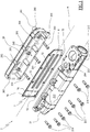
- the intake manifold 2 as shown in figure 1 , comprises an elongate box-shaped casing with a longitudinal axis A, provided with a substantially tub-shaped body 20, in which a plurality of outlet mouths 201 are realised, which branch from the bottom of the tub body 20 in the form of tubular connections 202, which for example, exhibit an axis that is perpendicular to the bottom of the tub body, but can also be arranged differently.
- the tub body 10 is fixed to the head of the motor 1 by first mounting screws 203, such that each outlet mouth 201 is set in fluid communication with a cylinder 10 of the internal combustion engine 1.
- the internal combustion engine 1 comprises 3 cylinders.
- the output mouths 201 face the respective 11 air supply lines (mixed with the exhaust gases) made in the head of the internal combustion engine 1, which lead directly into the cylinder 10, through conical-seat valves 12 (in the present embodiment 2) enslaved to the cylinder.
- the intake manifold 2 further comprises a lid 21 attached to the tub body 20, for example by means of screws 211 with the interposition of seal elements of the seal 8 type.
- the cover 21 is further substantially tub-shaped and a hollow shank 212 originates from a lateral wall thereof, which shank 212 has an axis that is longitudinally substantially parallel to the longitudinal axis A of the casing.
- a first inlet 213 is afforded on the lateral wall of the hollow shank 212 (upper in figure 1 ), which can be placed in fluid communication with a supply line (shown only schematically in figure 4 ) of the fresh comburent air aspirated from the outside environment.
- a second inlet mouth 214 is further afforded on the lateral wall of the hollow shank 212, which is placed in fluid communication with the terminal branch of the recirculation conduit 60, in which the exhaust gases cooled by the heat exchanger 61 are recirculated.
- a further second inlet mouth might be obtained in the side wall of the hollow shank 212 suitable for being placed in fluid communication with the terminal branch of the bypass conduit 62, in which the exhaust gases that have not been made to pass through the heat exchanger 60 recirculate, for example as they are already sufficiently cool (engine start-up) or because their thermal contribution is used to heat the engine.
- the intake manifold 2 comprises at least a wall 7 provided with at least an opening 70, which can divide the internal volume of the box casing 2 of the intake manifold into two chambers communicating with each other through the opening 70;
- the first chamber 215 is, for example, defined by the internal volume of the lid 21 and is placed in communication with the first inlet mouth 213 and the mouth second inlet mouth 214, while the second chamber 204 is, for example, defined by the internal volume of the tub body 20 and is placed in communication with the output mouths 201.
- the wall 7 is advantageously positioned in front of the outlet mouths 201, i.e. it lies in a substantially parallel plane to the longitudinal axis A of the box casing of the manifold inlet 2 and exhibits zones that are aligned with the outlet mouths 201 along the longitudinal axis of tube connections 202.
- the opening 70 is substantially dealigned in plan view with respect to the longitudinal axis of the tube connections 202; the wall 7 thus defines, via the opening 70, a connector which defines a substantially dog-leg shaped connection between the first chamber 215 and the second chamber 204 such as to increase the turbulence of the gases (air and exhaust gases) which cross the intake manifold 2, at the same time mixing the gases.
- the presence of the wall and the opening 70 thereof inside the intake manifold 2 enables the distance that the gases must travel in order to move from the respective inlet mouths 213 and 214 to the outlet mouths 201 to be increased, thus enabling an improvement in the mixing conditions between the air and exhaust gases.
- the wall 7 is plate-shaped, substantially rectangular and superposes, closing both the open end (opposite the bottom) of the tank body 20 and the lid 21.
- the opening 70 is an (also rectangular) opening, perimetrally closed and made at a side area of the wall 7, i.e. able to be placed, in use, in a distal zone from the first and the second inlet mouth, respectively 213 and 214.
- the wall 7 further comprises deflector means fixed at a side of the opening 70 and configured such as to reduce load loss of the gases (air and combusted gases) crossing the opening itself, when they pass from the first chamber 215 to the second chamber 204.
- the deflector means in the present example, comprise a lug 71 originating from the lateral edge of the opening 70 in proximity of the output ports 201 and bent in a U-shape on the wall 7, such as to produce a rounding of the sharp edge that the wall forms in the crank connection defined internally of the intake manifold 2.
- the wall 7 is made from a metal plate in which the opening 70 is obtained by cutting, a lateral edge of which (which faces towards the central zone of the wall) is bent on the wall 7 on the side which, in use, is destined to be facing towards the outlet mouths 201.
- the wall 7 can be realised in a different material and with different forming techniques.
- the wall 7 is removably associated to the casing of the intake manifold 2.
- the perimeter edge of the wall 7 is removably constrained and clamped between the tub body 20 and the lid 21, interposed between them when, by means of the second screws 211, the lid 21 is fixed to the tub body.
- the perimeter edge 7 of the wall which delimits the wall zone 7 separating the two chambers 204 and 215, comprises a series of eyelets 72 suitable for receiving, with play, the second screws 211 themselves, which then screw into appropriate threaded seatings 205 afforded in the free and of the tub body 20.
- the sealing elements i.e. the seal 8 is configured such as to be interposed both between the wall 7 and the tank body 20, and between the wall 7 and the lid 21.
- the seal 8 can be a single seal, having a substantially C shape, ring-closed on itself and suitable for bordering the perimeter edge of the wall 7 in such a way as to laterally clad it on both sides; alternatively two distinct annular seals can be comprised, fixed on opposite sides with respect to the wall 7.
- the seal 8 (or seals) can be fixed to the perimeter edge of the wall 7, for example by gluing or inserting in suitable housing slots.
- the seal 8 can be fixed to the perimeter edge 7 of the wall by co-moulding, for example injection moulding, with the perimeter edge of the wall itself.
- the fluid fresh air and exhaust gas
- the fluid which enters through the hollow shank 212 into the first chamber 215, longitudinally crosses the first chamber 215 and is retained in the first chamber 5 by the wall 7.
- the fluid passes into the second chamber 204 following the dogleg path of the wall 7, as shown in figure 3 .
- the dogleg bend the fluid passes round enables optimal mixing of the fresh air with the exhaust gases.
- the fluid is then forced back through the intake conduit 2 along the second chamber 204 and from there enters the tubular connections 202, then to be fed into the respective cylinders 10.
- An alternative embodiment of the wall 7, of which a first example is shown in figure 5 comprises a plurality of openings 70, as described above, separate from one another and distributed in the wall zone which is destined to divide the two chambers 204 and 215.
- the openings 70 are afforded in the wall 7 at the each outlet mouth 201 (facing in proximity thereof) in such a way as each to be dealigned with respect to the longitudinal axis of the respective tubular connection 202 serving the outlet mouths themselves.
- the wall 7 is composed of closed portions 25 alternated with a series of openings 70 aligned vertically as shown in figure 5 (it is alternatively possible that a single vertically elongate opening is present), in which each closed portion is at least partially aligned (along the longitudinal axis of the tube connector 202) to an outlet mouth 201 while each series of openings 70 precedes and follows (with respect to the longitudinal axis A of the wall 7) a closed portion.
- the fluid which enters the first chamber 215 via the hollow shank 212, crosses the wall 7 via the openings 70 and, being deviated by the closed portions of the wall 7 that define dogleg paths between the chambers 215 and 204, passes into the second chamber 204, mixing fresh air with the exhaust gas, and enters the respective connection tube 202 in order then to be supplied into each cylinder 10.
- the openings 70 can also be variously positioned in the wall 7 and can be of any shape and dimension, according to constructional requirements.
- the wall 7, in this embodiment too, comprises the deflector means, i.e. a plurality of lugs 71 associated, as described above, to each opening or possibly to only some thereof.
Description
- The present invention relates to an intake manifold of comburent air for an internal combustion engine, usually an internal combustion engine of vehicles, which is provided with an exhaust gas recirculation system.
- As is known, an internal combustion engine is conventionally provided with an intake manifold, an exhaust manifold, an intake line for conveying fresh air from the environment into the intake manifold, and an exhaust line for conveying the exhaust gas from the exhaust manifold to the environment. With the aim of reducing the polluting emissions, the majority of internal combustion engines, especially Diesel engines, are further provided with a recirculating system of the exhaust gases (EGR), selectively activatable for recirculating a part of the exhaust gases from the exhaust manifold in the intake manifold.
- In this way, a fraction of exhaust gas is mixed with the fresh air in inlet and the mixture supplies the engine cylinders, thus reducing the production of nitrogen oxides (NOx) during the combustion process.
- Conventional EGR systems exhibit an EGR conduit which places the exhaust manifold in connection with the intake manifold, an EGR heat exchanger of the exhaust gases before mixture with the aspirated air, and an electronically-controlled EGR valve, directly managed by a control board, for regulating the exhaust gas flow rate to be recirculated in the EGR conduit. The effect of the EGR system is negative if the exhaust gases recirculated are too cold, for example on engine start-up; too-cold exhaust gases can actually have a negative effect on the combustion processes.
- For this reason, with the aim of accelerating the heating of the exhaust gases or the engine starting from the engine, the EGR system might further comprise a bypass conduit, connected in parallel to the EGR heat exchanger, and a further valve which selects the passage of the exhaust gases in the bypass conduit, thus preventing passage of the exhaust gases internally of the EGR heat exchanger during the initial cold start-up phases of the motor or in other appropriate operating situations.
- The intake manifold therefore comprises a first inlet mouth communicating with the intake line and a second inlet mouth communicating with the EGR conduit (and/or the by-pass conduit) and a plurality of outlet mouths, each communicating with a respective cylinder of the engine.
- The EGR systems of known type, however, are not free of drawbacks, among which is the fact that the fresh air and the exhaust gases in inlet into the intake manifold, are not always sufficiently mixed with one another, so that the distribution of the exhaust gas among the engine cylinders is not always optimal, and gives rise to a non-homogeneous combustion among the various cylinders, which makes the whole recirculating system not particularly efficient.
- In particular, in the cylinders in which a quantity of fresh air will enter which is greater than what is desired, a greater formation of NOx will occur following the combustion, while in cylinders where a quantity of gas that is greater than the expected amount enters, a lower combustion temperature will be obtained, with a consequent greater production of uncombusted materials and particulate.
- In order to the above-mentioned drawbacks in the prior art, an improved intake manifold of the comburent air for an internal combustion engine, according to the preamble of
claim 1, has been disclosed in documents D1 (EP 0 764 781 ) and D5. - The intake manifold comprises a wall positioned in front of each of the outlet mouths and suitable for dividing the internal volume of the intake manifold into two chamber, the first chamber being placed in communication with the first inlet mouth and the second chamber being placed in communication with the outlet mouths, the wall having a plurality of openings suitable for placing the first chamber and the second chamber in communication, in order to promote the mixture of intake air with the EGR gas.
- The intake manifold according to D1 and D5 increases the mixture of intake air with the EGR gas respect to the EGR systems of known type, but not so efficiently.
- An aim of the present invention is to obviate the above-mentioned drawbacks in the prior art, with a solution that is simple, rational and relatively inexpensive.
- The aims are attained by the characteristics of the invention as reported in the independent claims. The dependent claims delineate preferred and/or particularly advantageous aspects of the invention.
- In particular the invention discloses an intake manifold of the comburent air for an internal combustion engine provided with a recirculating conduit of the exhaust gases, wherein the intake manifold comprises a first inlet mouth which will be placed in communication with a supply line of the comburent air, a second inlet mouth which will be set in communication with the recirculating conduit of the exhaust gases, and a plurality of outlet mouths, each of which is suitable for being placed in communication with a respective cylinder of the internal combustion engine.
- In the invention, the intake manifold comprises at least a wall positioned in front of each of the outlet mouths and suitable for dividing the internal volume of the intake manifold into two chambers, the first chamber being set in communication with the first inlet mouth and the second inlet mouth and the second chamber being set in communication with the outlet mouths, the wall defining an opening destined to set the first chamber and the second chamber in communication.
- Thanks to this solution, the mixture of the fresh air and the exhaust gases in the intake manifold is optimised, at the same time optimising the controllability and efficiency of the combustion process in the engine cylinders.
- Further, the recirculated exhaust gases and the fresh air are uniformly mixed with each other and uniformly distributed to the outlet mouths, with considerable advantages in terms of uniformity of the combustion in the cylinders.
- An aspect of the invention is, further, that the opening is substantially dealigned with respect to the outlet mouths, the opening and the wall defining a substantially dogleg pathway between the inlet mouths and the outlet mouths.
- Thus, the flow of gas (fresh air and exhaust gas) is forced to follow a tortuous path internally of the manifold intake, such as to ensure optimum mixing of the two gases.
- In a still further aspect of the invention, the intake manifold comprises deflector means associated with the wall at the position of opening, for reducing the load loss of the gases crossing the opening as they pass from the first chamber to the second chamber.
- Thanks to this detail, the passage of the gas mixture through the opening of the wall results in a limited load loss and gases are conveyed into the second chamber towards the outlet thereof.
- In addition, in a further aspect of the invention a box casing is comprised, with a substantially tub-shaped body in which the outlet mouths are comprised, fixable to the head of the internal combustion engine, and a lid fixed to the tub body, with an interposing of seal elements, in which the first inlet mouth and the second inlet mouth are defined.
- Further, the perimeter edge of the wall is advantageously suitable for being removably constrained by clamping between the tub body and the lid, the seal elements being interposed, between the wall and, respectively, the tub body and the lid.
- In this way the wall can be easily removed, for cleaning, maintenance and/or replacement.
- In a further aspect of the invention an engine is provided, comprising a plurality of combustion cylinders and provided with an intake manifold, as described above, and provided with an exhaust manifold and an exhaust gas recirculation system destined to recirculate part of the exhaust gases exiting from the exhaust manifold entrance in inlet to the intake manifold.
- Further characteristics and advantages of the invention will emerge from a reading of the following description, given by way non-limiting example, with the aid of the figures illustrated in the attached drawings.
-
Figure 1 is an axonometric exploded view of the manifold intake of the invention. -
Figure 2 is a lateral view of a detail of the head of the internal combustion engine including the intake manifoldfigure 1 , partially sectioned respect to a longitudinal plane. -
Figure 3 is a view from above of the combustion engine offigure 2 , partially sectioned along section line III-III offigure 2 . -
Figure 4 is a schematic view of the internal combustion engine of the invention, equipped with the exhaust gas recirculation system. -
Figure 5 is an axonometric view of an alternative embodiment of a wall, according to the invention. - With particular reference to the figures of the drawings, an internal combustion engine is denoted in its entirety by reference numeral 51, in this case a Diesel motor.
- The
internal combustion engine 1 has anintake manifold 2 and anexhaust manifold 3. - The
intake manifold 2 is connected to anintake line 4 for transporting fresh air from the environment into theinternal combustion engine 1, while theexhaust manifold 3 is conventionally connected to anexhaust line 5 such as to convey the exhaust gases from theinternal combustion engine 1 into the environment. - The
internal combustion engine 1 is equipped with an exhaust gas recirculation system (EGR), denoted in its entirety by 6, which is provided for recycling and supply of the exhaust gases into theinternal combustion engine 1 in order to reduce emissions of nitrogen oxides (NOx). - The
EGR system 6 comprises arecirculation conduit 60 which connects theexhaust manifold 3 directly to theintake manifold 2 and aheat exchanger device 61, generally called an EGR cooler, which is in fluid communication with therecirculation conduit 60, for cooling the exhaust gases that flow into it. - The
heat exchanger 61 is of a conventional type, for example with a tube bundle or plates, and the exhaust gas flowing into therecirculation conduit 60 is cooled by it, for example, with a coolant that also cools theengine 1 or which, alternatively, is dedicated only to the cooling of exhaust gases. To this end, theheat exchanger 61 is hydraulically connected to a circuit of a coolant fluid, known in the sector, in which the coolant fluid is maintained
physically separated from the exhaust gases to be cooled. - In more detail, a
valve 600 is associated upstream or downstream of theheat exchanger 61 with therecirculation conduit 60, the EGR valve, controlled by an electric control board, being of a type known to a technical expert in the field, and being suitable for regulating the exhaust gas flow overall directed from theexhaust manifold 3 to theintake manifold 2 through therecirculation conduit 60. - Further, the
EGR system 6 may comprise abypass conduit 62, which is indicated only by way of example in a broken line infigure 4 , which is connected in parallel to theheat exchanger 61, for example, on therecirculation conduit 60 or directly connected (upstream of the gas crossing direction) with theexhaust manifold 3 and downstream of themanifold intake 2. - In this case, a
valve 620 is associated with thebypass conduit 62 in order to selectively allow or block the flow of exhaust gases through the bypass itself. - The
intake manifold 2, as shown infigure 1 , comprises an elongate box-shaped casing with a longitudinal axis A, provided with a substantially tub-shaped body 20, in which a plurality ofoutlet mouths 201 are realised, which branch from the bottom of thetub body 20 in the form oftubular connections 202, which for example, exhibit an axis that is perpendicular to the bottom of the tub body, but can also be arranged differently. - The
tub body 10 is fixed to the head of themotor 1 byfirst mounting screws 203, such that eachoutlet mouth 201 is set in fluid communication with acylinder 10 of theinternal combustion engine 1. - In the illustrated example the
internal combustion engine 1 comprises 3 cylinders. - In practice, the
output mouths 201 face the respective 11 air supply lines (mixed with the exhaust gases) made in the head of theinternal combustion engine 1, which lead directly into thecylinder 10, through conical-seat valves 12 (in the present embodiment 2) enslaved to the cylinder. - The
intake manifold 2 further comprises alid 21 attached to thetub body 20, for example by means ofscrews 211 with the interposition of seal elements of theseal 8 type. - The
cover 21 is further substantially tub-shaped and ahollow shank 212 originates from a lateral wall thereof, whichshank 212 has an axis that is longitudinally substantially parallel to the longitudinal axis A of the casing. - A
first inlet 213 is afforded on the lateral wall of the hollow shank 212 (upper infigure 1 ), which can be placed in fluid communication with a supply line (shown only schematically infigure 4 ) of the fresh comburent air aspirated from the outside environment. - A
second inlet mouth 214 is further afforded on the lateral wall of thehollow shank 212, which is placed in fluid communication with the terminal branch of therecirculation conduit 60, in which the exhaust gases cooled by theheat exchanger 61 are recirculated. - In the illustrated example, a further second inlet mouth (not shown in the figures) might be obtained in the side wall of the
hollow shank 212 suitable for being placed in fluid communication with the terminal branch of thebypass conduit 62, in which the exhaust gases that have not been made to pass through theheat exchanger 60 recirculate, for example as they are already sufficiently cool (engine start-up) or because their thermal contribution is used to heat the engine. - The
intake manifold 2 comprises at least awall 7 provided with at least anopening 70, which can divide the internal volume of thebox casing 2 of the intake manifold into two chambers communicating with each other through theopening 70; thefirst chamber 215 is, for example, defined by the internal volume of thelid 21 and is placed in communication with thefirst inlet mouth 213 and the mouthsecond inlet mouth 214, while thesecond chamber 204 is, for example, defined by the internal volume of thetub body 20 and is placed in communication with theoutput mouths 201. - The
wall 7 is advantageously positioned in front of theoutlet mouths 201, i.e. it lies in a substantially parallel plane to the longitudinal axis A of the box casing of themanifold inlet 2 and exhibits zones that are aligned with theoutlet mouths 201 along the longitudinal axis oftube connections 202. - In practice, the opening 70 is substantially dealigned in plan view with respect to the longitudinal axis of the
tube connections 202; thewall 7 thus defines, via theopening 70, a connector which defines a substantially dog-leg shaped connection between thefirst chamber 215 and thesecond chamber 204 such as to increase the turbulence of the gases (air and exhaust gases) which cross theintake manifold 2, at the same time mixing the gases. - Further, the presence of the wall and the
opening 70 thereof inside theintake manifold 2 enables the distance that the gases must travel in order to move from therespective inlet mouths outlet mouths 201 to be increased, thus enabling an improvement in the mixing conditions between the air and exhaust gases. - The
wall 7 is plate-shaped, substantially rectangular and superposes, closing both the open end (opposite the bottom) of thetank body 20 and thelid 21. In the embodiment shown in the figures, the opening 70 is an (also rectangular) opening, perimetrally closed and made at a side area of thewall 7, i.e. able to be placed, in use, in a distal zone from the first and the second inlet mouth, respectively 213 and 214. - The
wall 7 further comprises deflector means fixed at a side of theopening 70 and configured such as to reduce load loss of the gases (air and combusted gases) crossing the opening itself, when they pass from thefirst chamber 215 to thesecond chamber 204. - The deflector means, in the present example, comprise a
lug 71 originating from the lateral edge of theopening 70 in proximity of theoutput ports 201 and bent in a U-shape on thewall 7, such as to produce a rounding of the sharp edge that the wall forms in the crank connection defined internally of theintake manifold 2. - For example, the
wall 7 is made from a metal plate in which theopening 70 is obtained by cutting, a lateral edge of which (which faces towards the central zone of the wall) is bent on thewall 7 on the side which, in use, is destined to be facing towards theoutlet mouths 201. - It is however possible that the
wall 7 can be realised in a different material and with different forming techniques. - The
wall 7 is removably associated to the casing of theintake manifold 2. - In particular, the perimeter edge of the
wall 7 is removably constrained and clamped between thetub body 20 and thelid 21, interposed between them when, by means of thesecond screws 211, thelid 21 is fixed to the tub body. In the present example, theperimeter edge 7 of the wall, which delimits thewall zone 7 separating the twochambers eyelets 72 suitable for receiving, with play, thesecond screws 211 themselves, which then screw into appropriate threadedseatings 205 afforded in the free and of thetub body 20. - The sealing elements, i.e. the
seal 8, is configured such as to be interposed both between thewall 7 and thetank body 20, and between thewall 7 and thelid 21. - For example, the
seal 8 can be a single seal, having a substantially C shape, ring-closed on itself and suitable for bordering the perimeter edge of thewall 7 in such a way as to laterally clad it on both sides; alternatively two distinct annular seals can be comprised, fixed on opposite sides with respect to thewall 7. - The seal 8 (or seals) can be fixed to the perimeter edge of the
wall 7, for example by gluing or inserting in suitable housing slots. - Alternatively, the
seal 8 can be fixed to theperimeter edge 7 of the wall by co-moulding, for example injection moulding, with the perimeter edge of the wall itself. - The functioning of the
intake conduit 2, in the embodiment of the figures, is the following. - The fluid (fresh air and exhaust gas), which enters through the
hollow shank 212 into thefirst chamber 215, longitudinally crosses thefirst chamber 215 and is retained in thefirst chamber 5 by thewall 7. - Once the
opening 70 has been reached, the fluid passes into thesecond chamber 204 following the dogleg path of thewall 7, as shown infigure 3 . The dogleg bend the fluid passes round enables optimal mixing of the fresh air with the exhaust gases. - The fluid is then forced back through the
intake conduit 2 along thesecond chamber 204 and from there enters thetubular connections 202, then to be fed into therespective cylinders 10. - An alternative embodiment of the
wall 7, of which a first example is shown infigure 5 , comprises a plurality ofopenings 70, as described above, separate from one another and distributed in the wall zone which is destined to divide the twochambers - The
openings 70 are afforded in thewall 7 at the each outlet mouth 201 (facing in proximity thereof) in such a way as each to be dealigned with respect to the longitudinal axis of therespective tubular connection 202 serving the outlet mouths themselves. - In practice, in this embodiment the
wall 7 is composed of closed portions 25 alternated with a series ofopenings 70 aligned vertically as shown infigure 5 (it is alternatively possible that a single vertically elongate opening is present), in which each closed portion is at least partially aligned (along the longitudinal axis of the tube connector 202) to anoutlet mouth 201 while each series ofopenings 70 precedes and follows (with respect to the longitudinal axis A of the wall 7) a closed portion. - The fluid, which enters the
first chamber 215 via thehollow shank 212, crosses thewall 7 via theopenings 70 and, being deviated by the closed portions of thewall 7 that define dogleg paths between thechambers second chamber 204, mixing fresh air with the exhaust gas, and enters therespective connection tube 202 in order then to be supplied into eachcylinder 10. - The
openings 70 can also be variously positioned in thewall 7 and can be of any shape and dimension, according to constructional requirements. - The
wall 7, in this embodiment too, comprises the deflector means, i.e. a plurality oflugs 71 associated, as described above, to each opening or possibly to only some thereof. - The invention as it is conceived is susceptible to numerous changes and variants, all falling within the ambit of the inventive concept. Further, all the details can be replaced by other technically-equivalent elements.
- In practice the materials used, as well as the contingent shapes and dimensions, may be any according to needs, without forsaking the ambit of protection of the following claims.
Claims (9)
- An intake manifold (2) of comburent air for an internal combustion engine (1) provided with a recirculating conduit (60) of exhaust gases, wherein the intake manifold (2) comprises a first inlet mouth (213) suitable for being placed in communication with a supply line (4) of the comburent air, a second inlet mouth (214) suitable for being placed in communication with the recirculating conduit (60) of the exhaust gases, and a plurality of outlet mouths (201) each suitable for being placed in communication with a respective cylinder (10) of the internal combustion engine (1), at least a wall (7) positioned in front of each of the outlet mouths (201) and suitable for dividing the internal volume of the intake manifold (2) into two chambers (215, 204), the first chamber (215) being placed in communication with the first inlet mouth (213) and the second inlet mouth (214) and the second chamber (204) being placed in communication with the outlet mouths (201), the wall (7) defining at least an opening (70) suitable for placing the first chamber (215) and the second chamber (204) in communication, wherein it comprises seal elements (8) fixed to the perimeter edge of the wall (7) and characterised in that the wall (7) comprises a single opening (70) suitable for being positioned in a distal zone from the first and second inlet mouth (213, 214), and wherein the wall (7) comprises deflector means fixed at a side of the opening (70) and configured such as to reduce load loss of the gases crossing the opening itself, when they pass from the first chamber (215) to the second chamber (204), the deflector means comprising a lug (71) branching from the lateral edge of the opening (70) proximal to the outlet mouths (201) and bent in a U-shape on the wall (7), such as to produce a rounding of the edge that the wall (7) forms in the dogleg connection defined between the first chamber (215) and the second chamber (204).
- The intake manifold (2) of claim 1, wherein the seal elements comprise at least an annular gasket (8) suitable for bordering the perimeter edge of the wall (7).
- The intake manifold (2) of claim 2, wherein the gasket (8) exhibits a section that is substantially C-shaped, such as to cover the wall (7) laterally from both sides.
- The intake manifold (2) of claim 1, wherein the seal elements (8) are fixed to the perimeter edge of the wall (7), by means of at least one from among following fixing modes, including gluing, friction and co-moulding with the perimeter edge of the wall.
- The intake manifold (2) of claim 1, wherein the opening (70) is substantially dealigned with respect to the outlet mouths (201), the opening (70) and the wall (7) defining a substantially dogleg pathway between the inlet mouths (213, 214) and the outlet mouths (201).
- The intake manifold (2) of claim 1, characterised in that it comprises a hollow shank (212) which derives from the first chamber (215) with a longitudinal axis that is parallel to the longitudinal axis (A) of the manifold, the first inlet mouth (213) and the second inlet mouth (214) being afforded on the lateral surface of the hollow shank (212).
- The intake manifold (2) of claim 1, characterised in that it comprises a box casing, provided with a body (20) having substantially a tub shape, in which the outlet mouths (201) are afforded, which box casing is fixable to the head of the internal combustion motor (20), and a lid (21) fixed to the tub body (20), with an interposing of seal elements (8), in which the first inlet mouth (213) and the second inlet mouth (214) are defined.
- The intake manifold (2) of claim 7, wherein the perimeter edge of the wall (7) is suitable for being constrained removably by clamping between the tub body (20) and the lid (21), the seal elements (8) being interposed between the wall (7) and, respectively, the tub body (20) and the lid (21).
- An internal combustion engine (1) comprising a plurality of cylinders and provided with an intake manifold (2), according to any one of the preceding claims, an exhaust manifold (3) and an exhaust gas recirculation system (6) suitable for recirculating part of the exhaust gases from the exhaust manifold (3) in inlet to the intake manifold (2).
Applications Claiming Priority (1)
| Application Number | Priority Date | Filing Date | Title |
|---|---|---|---|
| IT000066A ITRE20110066A1 (en) | 2011-09-08 | 2011-09-08 | COMBUSTION AIR INTAKE MANIFOLD FOR AN INTERNAL COMBUSTION ENGINE EQUIPPED WITH EGR |
Publications (2)
| Publication Number | Publication Date |
|---|---|
| EP2568154A1 EP2568154A1 (en) | 2013-03-13 |
| EP2568154B1 true EP2568154B1 (en) | 2017-05-03 |
Family
ID=44872516
Family Applications (1)
| Application Number | Title | Priority Date | Filing Date |
|---|---|---|---|
| EP12177589.4A Active EP2568154B1 (en) | 2011-09-08 | 2012-07-24 | An intake manifold of comburent air for an internal combustion engine equipped with egr |
Country Status (4)
| Country | Link |
|---|---|
| US (1) | US8919315B2 (en) |
| EP (1) | EP2568154B1 (en) |
| ES (1) | ES2628057T3 (en) |
| IT (1) | ITRE20110066A1 (en) |
Families Citing this family (10)
| Publication number | Priority date | Publication date | Assignee | Title |
|---|---|---|---|---|
| CN104736833A (en) * | 2012-10-29 | 2015-06-24 | 卡特彼勒能源方案有限公司 | Intake assembly for an internal combustion engine and internal combustion engine with the same |
| CN103437922A (en) * | 2013-07-16 | 2013-12-11 | 东风朝阳朝柴动力有限公司 | Optimization device for intake pipe of diesel engine |
| US9556778B2 (en) * | 2013-12-10 | 2017-01-31 | Cummins Inc. | Waste heat recovery system including a clutched feedpump |
| JP6250893B2 (en) * | 2015-02-13 | 2017-12-20 | トヨタ自動車株式会社 | Blowby gas treatment device and intake manifold |
| EP3255273B1 (en) | 2016-06-10 | 2018-08-01 | FCA Italy S.p.A. | Intake manifold unit for an internal combustion engine |
| USD838292S1 (en) * | 2016-08-01 | 2019-01-15 | Full Tilt Performance Llc | Engine intake manifold |
| JP2019065808A (en) * | 2017-10-04 | 2019-04-25 | いすゞ自動車株式会社 | Intake system structure for internal combustion engine |
| JP6867282B2 (en) * | 2017-12-27 | 2021-04-28 | ヤンマーパワーテクノロジー株式会社 | Intake structure of multi-cylinder engine |
| JP6962873B2 (en) * | 2018-06-30 | 2021-11-05 | 株式会社クボタ | Engine intake structure |
| AT524259A1 (en) * | 2021-06-17 | 2022-04-15 | Avl List Gmbh | INLET COLLECTOR FOR AN ENGINE |
Family Cites Families (10)
| Publication number | Priority date | Publication date | Assignee | Title |
|---|---|---|---|---|
| US5704326A (en) * | 1992-12-10 | 1998-01-06 | Hitachi, Ltd. | Air induction system for internal-combustion engine |
| US6032634A (en) * | 1994-11-02 | 2000-03-07 | Hitachi, Ltd. | Air induction system for internal-combustion engine |
| US5601059A (en) * | 1995-08-09 | 1997-02-11 | Brunswick Corporation | Fuel distribution insert for internal combustion engine |
| JP3680371B2 (en) * | 1995-09-21 | 2005-08-10 | いすゞ自動車株式会社 | Intake chamber |
| SE521988C2 (en) * | 1998-02-04 | 2003-12-23 | Volvo Lastvagnar Ab | Combustion engine arrangement |
| FR2783567B1 (en) * | 1998-09-23 | 2000-10-27 | Renault | INTAKE MANIFOLD FOR INTERNAL COMBUSTION ENGINE |
| DE102004024465A1 (en) * | 2004-05-14 | 2005-12-08 | Mann + Hummel Gmbh | intake system |
| US7237541B2 (en) * | 2004-09-23 | 2007-07-03 | Siemens Canada Limited | Modular intake manifold and integrated air intake system |
| US7036493B1 (en) * | 2004-10-08 | 2006-05-02 | General Motors Corporation | Intake manifold for an internal combustion engine |
| EP2333292B1 (en) * | 2009-12-09 | 2012-05-02 | Caterpillar Motoren GmbH & Co. KG | Mixing pipe for recirculated exhaust gas and air |
-
2011
- 2011-09-08 IT IT000066A patent/ITRE20110066A1/en unknown
-
2012
- 2012-07-24 ES ES12177589.4T patent/ES2628057T3/en active Active
- 2012-07-24 EP EP12177589.4A patent/EP2568154B1/en active Active
- 2012-08-31 US US13/600,923 patent/US8919315B2/en active Active
Non-Patent Citations (1)
| Title |
|---|
| None * |
Also Published As
| Publication number | Publication date |
|---|---|
| ES2628057T3 (en) | 2017-08-01 |
| US8919315B2 (en) | 2014-12-30 |
| US20130061825A1 (en) | 2013-03-14 |
| ITRE20110066A1 (en) | 2013-03-09 |
| EP2568154A1 (en) | 2013-03-13 |
Similar Documents
| Publication | Publication Date | Title |
|---|---|---|
| EP2568154B1 (en) | An intake manifold of comburent air for an internal combustion engine equipped with egr | |
| EP1154144B1 (en) | An internal-combustion engine provided with an exhaust gas recirculation system, in particular for a vehicle | |
| US6971377B2 (en) | Exhaust gas recirculation cooler with bypass flow | |
| CN104329195B (en) | Engine Inlet For EGR-Air Flow Distribution | |
| CN102257257B (en) | Gas intake device | |
| KR101156849B1 (en) | Heat exchanger module for adjusting the temperature of intake gas in a heat engine for a motor vehicle | |
| KR20000047594A (en) | Engine air intake manifold having built-in intercooler | |
| CN103206321A (en) | Intake Device Of Engine | |
| EP2333292B1 (en) | Mixing pipe for recirculated exhaust gas and air | |
| CN101495743A (en) | Valve arrangement for an exhaust gas recirculation device | |
| WO2009058965A1 (en) | Staged arrangement of egr coolers to optimize performance | |
| KR102169316B1 (en) | Egr valve unit and exhaust gas recirculation system having the same | |
| US6997144B2 (en) | Cylinder head structure for an internal combustion engine | |
| CN115210462A (en) | Engine | |
| KR20080098843A (en) | Exhaust gas recirculation system of vehicle | |
| WO2015098705A1 (en) | Cylinder head of engine | |
| KR20160069788A (en) | Water cooled type intercooler apparatus | |
| CN107178445B (en) | Gas reflux device | |
| JP4363176B2 (en) | Engine exhaust gas recirculation system | |
| KR20100116376A (en) | Exhaust gas recirculation system | |
| JP2007303436A (en) | Engine exhaust gas recirculation device | |
| JPH07259657A (en) | Exhaust gas recirculating device of v-engine | |
| JP2021161980A (en) | Egr system of engine | |
| JP2021113531A (en) | Intake device of engine | |
| KR102122836B1 (en) | Egr cooler unit and exhaust gas recirculation system having the same |
Legal Events
| Date | Code | Title | Description |
|---|---|---|---|
| PUAI | Public reference made under article 153(3) epc to a published international application that has entered the european phase |
Free format text: ORIGINAL CODE: 0009012 |
|
| AK | Designated contracting states |
Kind code of ref document: A1 Designated state(s): AL AT BE BG CH CY CZ DE DK EE ES FI FR GB GR HR HU IE IS IT LI LT LU LV MC MK MT NL NO PL PT RO RS SE SI SK SM TR |
|
| AX | Request for extension of the european patent |
Extension state: BA ME |
|
| 17P | Request for examination filed |
Effective date: 20130828 |
|
| RBV | Designated contracting states (corrected) |
Designated state(s): AL AT BE BG CH CY CZ DE DK EE ES FI FR GB GR HR HU IE IS IT LI LT LU LV MC MK MT NL NO PL PT RO RS SE SI SK SM TR |
|
| 17Q | First examination report despatched |
Effective date: 20150901 |
|
| REG | Reference to a national code |
Ref country code: DE Ref legal event code: R079 Ref document number: 602012031839 Country of ref document: DE Free format text: PREVIOUS MAIN CLASS: F02M0035100000 Ipc: F02M0025060000 |
|
| RIC1 | Information provided on ipc code assigned before grant |
Ipc: F02M 35/10 20060101ALI20160711BHEP Ipc: F02M 25/06 20060101AFI20160711BHEP Ipc: F02M 35/104 20060101ALI20160711BHEP Ipc: F02M 26/25 20160101ALI20160711BHEP Ipc: F02M 26/30 20160101ALI20160711BHEP |
|
| GRAP | Despatch of communication of intention to grant a patent |
Free format text: ORIGINAL CODE: EPIDOSNIGR1 |
|
| INTG | Intention to grant announced |
Effective date: 20160919 |
|
| GRAS | Grant fee paid |
Free format text: ORIGINAL CODE: EPIDOSNIGR3 |
|
| GRAJ | Information related to disapproval of communication of intention to grant by the applicant or resumption of examination proceedings by the epo deleted |
Free format text: ORIGINAL CODE: EPIDOSDIGR1 |
|
| GRAL | Information related to payment of fee for publishing/printing deleted |
Free format text: ORIGINAL CODE: EPIDOSDIGR3 |
|
| GRAP | Despatch of communication of intention to grant a patent |
Free format text: ORIGINAL CODE: EPIDOSNIGR1 |
|
| INTC | Intention to grant announced (deleted) | ||
| INTG | Intention to grant announced |
Effective date: 20170125 |
|
| GRAA | (expected) grant |
Free format text: ORIGINAL CODE: 0009210 |
|
| AK | Designated contracting states |
Kind code of ref document: B1 Designated state(s): AL AT BE BG CH CY CZ DE DK EE ES FI FR GB GR HR HU IE IS IT LI LT LU LV MC MK MT NL NO PL PT RO RS SE SI SK SM TR |
|
| REG | Reference to a national code |
Ref country code: GB Ref legal event code: FG4D |
|
| REG | Reference to a national code |
Ref country code: AT Ref legal event code: REF Ref document number: 890285 Country of ref document: AT Kind code of ref document: T Effective date: 20170515 Ref country code: CH Ref legal event code: EP |
|
| REG | Reference to a national code |
Ref country code: IE Ref legal event code: FG4D |
|
| REG | Reference to a national code |
Ref country code: DE Ref legal event code: R096 Ref document number: 602012031839 Country of ref document: DE |
|
| REG | Reference to a national code |
Ref country code: FR Ref legal event code: PLFP Year of fee payment: 6 |
|
| REG | Reference to a national code |
Ref country code: ES Ref legal event code: FG2A Ref document number: 2628057 Country of ref document: ES Kind code of ref document: T3 Effective date: 20170801 |
|
| REG | Reference to a national code |
Ref country code: NL Ref legal event code: MP Effective date: 20170503 |
|
| REG | Reference to a national code |
Ref country code: AT Ref legal event code: MK05 Ref document number: 890285 Country of ref document: AT Kind code of ref document: T Effective date: 20170503 |
|
| REG | Reference to a national code |
Ref country code: LT Ref legal event code: MG4D |
|
| PG25 | Lapsed in a contracting state [announced via postgrant information from national office to epo] |
Ref country code: FI Free format text: LAPSE BECAUSE OF FAILURE TO SUBMIT A TRANSLATION OF THE DESCRIPTION OR TO PAY THE FEE WITHIN THE PRESCRIBED TIME-LIMIT Effective date: 20170503 Ref country code: GR Free format text: LAPSE BECAUSE OF FAILURE TO SUBMIT A TRANSLATION OF THE DESCRIPTION OR TO PAY THE FEE WITHIN THE PRESCRIBED TIME-LIMIT Effective date: 20170804 Ref country code: AT Free format text: LAPSE BECAUSE OF FAILURE TO SUBMIT A TRANSLATION OF THE DESCRIPTION OR TO PAY THE FEE WITHIN THE PRESCRIBED TIME-LIMIT Effective date: 20170503 Ref country code: LT Free format text: LAPSE BECAUSE OF FAILURE TO SUBMIT A TRANSLATION OF THE DESCRIPTION OR TO PAY THE FEE WITHIN THE PRESCRIBED TIME-LIMIT Effective date: 20170503 Ref country code: HR Free format text: LAPSE BECAUSE OF FAILURE TO SUBMIT A TRANSLATION OF THE DESCRIPTION OR TO PAY THE FEE WITHIN THE PRESCRIBED TIME-LIMIT Effective date: 20170503 Ref country code: NO Free format text: LAPSE BECAUSE OF FAILURE TO SUBMIT A TRANSLATION OF THE DESCRIPTION OR TO PAY THE FEE WITHIN THE PRESCRIBED TIME-LIMIT Effective date: 20170803 |
|
| PG25 | Lapsed in a contracting state [announced via postgrant information from national office to epo] |
Ref country code: RS Free format text: LAPSE BECAUSE OF FAILURE TO SUBMIT A TRANSLATION OF THE DESCRIPTION OR TO PAY THE FEE WITHIN THE PRESCRIBED TIME-LIMIT Effective date: 20170503 Ref country code: LV Free format text: LAPSE BECAUSE OF FAILURE TO SUBMIT A TRANSLATION OF THE DESCRIPTION OR TO PAY THE FEE WITHIN THE PRESCRIBED TIME-LIMIT Effective date: 20170503 Ref country code: BG Free format text: LAPSE BECAUSE OF FAILURE TO SUBMIT A TRANSLATION OF THE DESCRIPTION OR TO PAY THE FEE WITHIN THE PRESCRIBED TIME-LIMIT Effective date: 20170803 Ref country code: IS Free format text: LAPSE BECAUSE OF FAILURE TO SUBMIT A TRANSLATION OF THE DESCRIPTION OR TO PAY THE FEE WITHIN THE PRESCRIBED TIME-LIMIT Effective date: 20170903 Ref country code: SE Free format text: LAPSE BECAUSE OF FAILURE TO SUBMIT A TRANSLATION OF THE DESCRIPTION OR TO PAY THE FEE WITHIN THE PRESCRIBED TIME-LIMIT Effective date: 20170503 Ref country code: PL Free format text: LAPSE BECAUSE OF FAILURE TO SUBMIT A TRANSLATION OF THE DESCRIPTION OR TO PAY THE FEE WITHIN THE PRESCRIBED TIME-LIMIT Effective date: 20170503 Ref country code: NL Free format text: LAPSE BECAUSE OF FAILURE TO SUBMIT A TRANSLATION OF THE DESCRIPTION OR TO PAY THE FEE WITHIN THE PRESCRIBED TIME-LIMIT Effective date: 20170503 |
|
| PG25 | Lapsed in a contracting state [announced via postgrant information from national office to epo] |
Ref country code: RO Free format text: LAPSE BECAUSE OF FAILURE TO SUBMIT A TRANSLATION OF THE DESCRIPTION OR TO PAY THE FEE WITHIN THE PRESCRIBED TIME-LIMIT Effective date: 20170503 Ref country code: DK Free format text: LAPSE BECAUSE OF FAILURE TO SUBMIT A TRANSLATION OF THE DESCRIPTION OR TO PAY THE FEE WITHIN THE PRESCRIBED TIME-LIMIT Effective date: 20170503 Ref country code: EE Free format text: LAPSE BECAUSE OF FAILURE TO SUBMIT A TRANSLATION OF THE DESCRIPTION OR TO PAY THE FEE WITHIN THE PRESCRIBED TIME-LIMIT Effective date: 20170503 Ref country code: CZ Free format text: LAPSE BECAUSE OF FAILURE TO SUBMIT A TRANSLATION OF THE DESCRIPTION OR TO PAY THE FEE WITHIN THE PRESCRIBED TIME-LIMIT Effective date: 20170503 Ref country code: SK Free format text: LAPSE BECAUSE OF FAILURE TO SUBMIT A TRANSLATION OF THE DESCRIPTION OR TO PAY THE FEE WITHIN THE PRESCRIBED TIME-LIMIT Effective date: 20170503 |
|
| REG | Reference to a national code |
Ref country code: DE Ref legal event code: R097 Ref document number: 602012031839 Country of ref document: DE |
|
| PG25 | Lapsed in a contracting state [announced via postgrant information from national office to epo] |
Ref country code: SM Free format text: LAPSE BECAUSE OF FAILURE TO SUBMIT A TRANSLATION OF THE DESCRIPTION OR TO PAY THE FEE WITHIN THE PRESCRIBED TIME-LIMIT Effective date: 20170503 |
|
| REG | Reference to a national code |
Ref country code: CH Ref legal event code: PL |
|
| PLBE | No opposition filed within time limit |
Free format text: ORIGINAL CODE: 0009261 |
|
| STAA | Information on the status of an ep patent application or granted ep patent |
Free format text: STATUS: NO OPPOSITION FILED WITHIN TIME LIMIT |
|
| 26N | No opposition filed |
Effective date: 20180206 |
|
| REG | Reference to a national code |
Ref country code: IE Ref legal event code: MM4A |
|
| PG25 | Lapsed in a contracting state [announced via postgrant information from national office to epo] |
Ref country code: IE Free format text: LAPSE BECAUSE OF NON-PAYMENT OF DUE FEES Effective date: 20170724 Ref country code: LI Free format text: LAPSE BECAUSE OF NON-PAYMENT OF DUE FEES Effective date: 20170731 Ref country code: CH Free format text: LAPSE BECAUSE OF NON-PAYMENT OF DUE FEES Effective date: 20170731 |
|
| PG25 | Lapsed in a contracting state [announced via postgrant information from national office to epo] |
Ref country code: SI Free format text: LAPSE BECAUSE OF FAILURE TO SUBMIT A TRANSLATION OF THE DESCRIPTION OR TO PAY THE FEE WITHIN THE PRESCRIBED TIME-LIMIT Effective date: 20170503 |
|
| REG | Reference to a national code |
Ref country code: BE Ref legal event code: MM Effective date: 20170731 |
|
| PG25 | Lapsed in a contracting state [announced via postgrant information from national office to epo] |
Ref country code: LU Free format text: LAPSE BECAUSE OF NON-PAYMENT OF DUE FEES Effective date: 20170724 |
|
| REG | Reference to a national code |
Ref country code: FR Ref legal event code: PLFP Year of fee payment: 7 |
|
| PG25 | Lapsed in a contracting state [announced via postgrant information from national office to epo] |
Ref country code: BE Free format text: LAPSE BECAUSE OF NON-PAYMENT OF DUE FEES Effective date: 20170731 |
|
| PG25 | Lapsed in a contracting state [announced via postgrant information from national office to epo] |
Ref country code: MT Free format text: LAPSE BECAUSE OF NON-PAYMENT OF DUE FEES Effective date: 20170724 |
|
| PG25 | Lapsed in a contracting state [announced via postgrant information from national office to epo] |
Ref country code: HU Free format text: LAPSE BECAUSE OF FAILURE TO SUBMIT A TRANSLATION OF THE DESCRIPTION OR TO PAY THE FEE WITHIN THE PRESCRIBED TIME-LIMIT; INVALID AB INITIO Effective date: 20120724 Ref country code: MC Free format text: LAPSE BECAUSE OF FAILURE TO SUBMIT A TRANSLATION OF THE DESCRIPTION OR TO PAY THE FEE WITHIN THE PRESCRIBED TIME-LIMIT Effective date: 20170503 |
|
| PG25 | Lapsed in a contracting state [announced via postgrant information from national office to epo] |
Ref country code: CY Free format text: LAPSE BECAUSE OF NON-PAYMENT OF DUE FEES Effective date: 20170503 |
|
| PG25 | Lapsed in a contracting state [announced via postgrant information from national office to epo] |
Ref country code: MK Free format text: LAPSE BECAUSE OF FAILURE TO SUBMIT A TRANSLATION OF THE DESCRIPTION OR TO PAY THE FEE WITHIN THE PRESCRIBED TIME-LIMIT Effective date: 20170503 |
|
| PG25 | Lapsed in a contracting state [announced via postgrant information from national office to epo] |
Ref country code: TR Free format text: LAPSE BECAUSE OF FAILURE TO SUBMIT A TRANSLATION OF THE DESCRIPTION OR TO PAY THE FEE WITHIN THE PRESCRIBED TIME-LIMIT Effective date: 20170503 |
|
| PG25 | Lapsed in a contracting state [announced via postgrant information from national office to epo] |
Ref country code: PT Free format text: LAPSE BECAUSE OF FAILURE TO SUBMIT A TRANSLATION OF THE DESCRIPTION OR TO PAY THE FEE WITHIN THE PRESCRIBED TIME-LIMIT Effective date: 20170503 |
|
| PG25 | Lapsed in a contracting state [announced via postgrant information from national office to epo] |
Ref country code: AL Free format text: LAPSE BECAUSE OF FAILURE TO SUBMIT A TRANSLATION OF THE DESCRIPTION OR TO PAY THE FEE WITHIN THE PRESCRIBED TIME-LIMIT Effective date: 20170503 |
|
| PGFP | Annual fee paid to national office [announced via postgrant information from national office to epo] |
Ref country code: ES Payment date: 20220801 Year of fee payment: 11 |
|
| PGFP | Annual fee paid to national office [announced via postgrant information from national office to epo] |
Ref country code: IT Payment date: 20230529 Year of fee payment: 12 |
|
| P01 | Opt-out of the competence of the unified patent court (upc) registered |
Effective date: 20230817 |
|
| PGFP | Annual fee paid to national office [announced via postgrant information from national office to epo] |
Ref country code: GB Payment date: 20230727 Year of fee payment: 12 |
|
| PGFP | Annual fee paid to national office [announced via postgrant information from national office to epo] |
Ref country code: FR Payment date: 20230725 Year of fee payment: 12 Ref country code: DE Payment date: 20230727 Year of fee payment: 12 |