EP2568151B1 - Serrated nozzle trailing edge for gas turbine - Google Patents
Serrated nozzle trailing edge for gas turbine Download PDFInfo
- Publication number
- EP2568151B1 EP2568151B1 EP12195123.0A EP12195123A EP2568151B1 EP 2568151 B1 EP2568151 B1 EP 2568151B1 EP 12195123 A EP12195123 A EP 12195123A EP 2568151 B1 EP2568151 B1 EP 2568151B1
- Authority
- EP
- European Patent Office
- Prior art keywords
- nozzle
- lobe
- lobes
- apexes
- trailing edges
- Prior art date
- Legal status (The legal status is an assumption and is not a legal conclusion. Google has not performed a legal analysis and makes no representation as to the accuracy of the status listed.)
- Active
Links
Images


Classifications
-
- F—MECHANICAL ENGINEERING; LIGHTING; HEATING; WEAPONS; BLASTING
- F02—COMBUSTION ENGINES; HOT-GAS OR COMBUSTION-PRODUCT ENGINE PLANTS
- F02K—JET-PROPULSION PLANTS
- F02K1/00—Plants characterised by the form or arrangement of the jet pipe or nozzle; Jet pipes or nozzles peculiar thereto
- F02K1/40—Nozzles having means for dividing the jet into a plurality of partial jets or having an elongated cross-section outlet
-
- F—MECHANICAL ENGINEERING; LIGHTING; HEATING; WEAPONS; BLASTING
- F02—COMBUSTION ENGINES; HOT-GAS OR COMBUSTION-PRODUCT ENGINE PLANTS
- F02K—JET-PROPULSION PLANTS
- F02K1/00—Plants characterised by the form or arrangement of the jet pipe or nozzle; Jet pipes or nozzles peculiar thereto
- F02K1/38—Introducing air inside the jet
- F02K1/386—Introducing air inside the jet mixing devices in the jet pipe, e.g. for mixing primary and secondary flow
-
- F—MECHANICAL ENGINEERING; LIGHTING; HEATING; WEAPONS; BLASTING
- F02—COMBUSTION ENGINES; HOT-GAS OR COMBUSTION-PRODUCT ENGINE PLANTS
- F02K—JET-PROPULSION PLANTS
- F02K1/00—Plants characterised by the form or arrangement of the jet pipe or nozzle; Jet pipes or nozzles peculiar thereto
- F02K1/46—Nozzles having means for adding air to the jet or for augmenting the mixing region between the jet and the ambient air, e.g. for silencing
-
- F—MECHANICAL ENGINEERING; LIGHTING; HEATING; WEAPONS; BLASTING
- F05—INDEXING SCHEMES RELATING TO ENGINES OR PUMPS IN VARIOUS SUBCLASSES OF CLASSES F01-F04
- F05D—INDEXING SCHEME FOR ASPECTS RELATING TO NON-POSITIVE-DISPLACEMENT MACHINES OR ENGINES, GAS-TURBINES OR JET-PROPULSION PLANTS
- F05D2250/00—Geometry
- F05D2250/60—Structure; Surface texture
- F05D2250/61—Structure; Surface texture corrugated
- F05D2250/611—Structure; Surface texture corrugated undulated
-
- F—MECHANICAL ENGINEERING; LIGHTING; HEATING; WEAPONS; BLASTING
- F05—INDEXING SCHEMES RELATING TO ENGINES OR PUMPS IN VARIOUS SUBCLASSES OF CLASSES F01-F04
- F05D—INDEXING SCHEME FOR ASPECTS RELATING TO NON-POSITIVE-DISPLACEMENT MACHINES OR ENGINES, GAS-TURBINES OR JET-PROPULSION PLANTS
- F05D2250/00—Geometry
- F05D2250/70—Shape
-
- F—MECHANICAL ENGINEERING; LIGHTING; HEATING; WEAPONS; BLASTING
- F05—INDEXING SCHEMES RELATING TO ENGINES OR PUMPS IN VARIOUS SUBCLASSES OF CLASSES F01-F04
- F05D—INDEXING SCHEME FOR ASPECTS RELATING TO NON-POSITIVE-DISPLACEMENT MACHINES OR ENGINES, GAS-TURBINES OR JET-PROPULSION PLANTS
- F05D2260/00—Function
- F05D2260/96—Preventing, counteracting or reducing vibration or noise
Definitions
- This invention relates to exhaust flow nozzles, such as those used in gas turbine engines, having serrations or undulations to reduce noise.
- the trough trailing edge 42 is recessed relative to the lobe trailing edge 40.
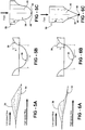
- Another variation is shown in Figures 5A-5C , and includes tabs 46 having curved apexes 48 having a terminal point 50 similar to the geometries shown in Figures 3A-4C .
- Figure 6A-7C have triangular-like tabs 46 that come to sharp points at their apexes.
- the preferred lobe features such as shape and h/w ratio are distinct from prior art for lobed mixers in that the side-walls are substantially non-vertical (so as to avoid high concentrations of vorticity and mixing) and the h/w ratios are usually of order 1 or smaller, significantly lower than ratios of 4-6 characteristic of lobed mixers.
- Axial vorticity generated by this configuration was obtained using Reynolds-averaged Navier Stokes computations.
- contouring of the (lobe) trough edges coupled with the lobe feature allows and enhances radial flow in the base region, producing more circulation without increasing drag penalty.
- the lobe provides a means to direct a portion of the exit exhaust in the axial direction and adjust the effective area at the nozzle exit. In this way, the undulation of the nozzle edge expands the design space enabling optimal nozzle design to reduce thrust penalty.
Description
- This invention relates to exhaust flow nozzles, such as those used in gas turbine engines, having serrations or undulations to reduce noise.
- The generation of noise from turbulent jet exhausts is of significant practical interest for low and moderate bypass ratio engines used in subsonic civil transports. The jet exhaust noise is one component of overall engine noise, and is particularly important at take-off and cutback conditions. For high bypass ratio engines, the jet noise contribution is reduced, but it is still a factor especially with continually tightening of noise restrictions.
- Prior approaches to jet noise reduction have relied primarily on mixing enhancement, where the aim is to promote the exchange of momentum between the high-speed primary stream and the lower-momentum secondary flow (i.e. fan bypass and/or ambient flight stream). Tabs and chevron-type devices have been used for single stream and separate flow exhaust systems. Lobed mixers have been used for mixed-flow exhausts.
- An inherent shortcoming of the aforementioned mixing devices is their tendency to generate parasitic high-frequency noise. Thus, while low-frequency noise reduction can readily approach 2-4 dB in noise spectra, reductions in overall (community) noise metrics such as Effective Perceived Noise Level (EPNL) are appreciably lower. In some instances, the high frequency noise penalty can completely offset low-frequency reduction, resulting in increased EPNL.
- A second shortcoming of external plume mixing devices is adverse impact on aerodynamic performance (axial thrust). Tabs and chevrons typically increase Total Specific Fuel Consumption (TSFC), and can adversely affect nozzle discharge characteristics at off-design points in the flight envelope.
- A prior art gas turbine nozzle including a lobe mixer is disclosed in
GB-A-2085088 WO-A-98/59162 EP-A-1496238 . - The present invention provides a nozzle for a gas turbine engine, as set forth in claim 1.
- These and other features of the present invention can be best understood from the following specification and drawings, the following of which is a brief description.
-
-
Figure 1A is a schematic cross-sectional view of a prior art separate exhaust flow gas turbine. -
Figure 1B is a schematic cross-sectional view of a prior art confluent or mixed exhaust flow gas turbine. -
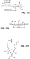
Figure 1C is a side elevational view of an example separate exhaust flow gas turbine with the inventive undulation on the core exhaust nozzle. -
Figure 1D is an end view of both the core and fan exhaust nozzles with the inventive undulations. -
Figure 2A is a side elevational view of an inventive exhaust nozzle. -
Figure 2B is a perspective view of the exhaust nozzle shown inFigure 2A . -
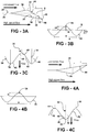
Figure 3A is a schematic side view of a lobe recessed relative to a trough. -
Figure 3B is a schematic end view of the lobe and trough shown inFigure 3A . -
Figure 3C is a schematic top view of the lobe and trough shown inFigure 3A -
Figure 4A is a schematic side view of a trough recessed relative to a lobe. -
Figure 4B is a schematic end view of the lobe and trough shown inFigure 4A . -
Figure 4C is a schematic top view of the lobe and trough shown inFigure 4A . -
Figure 5A is a side elevational view of one example lobe and trough shape and trailing edge shapes. -
Figure 5B is a schematic end view of the lobe and trough shown inFigure 5A . -
Figure 5C is a top elevational view of the lobe and trough shown inFigure 5A . -
Figure 6A is a side elevational view of another example lobe and trough shape and trailing edge shapes. -
Figure 6B is a schematic end view of the lobe and trough shown inFigure 6A . -
Figure 6C is a top elevational view of the lobe and trough shown inFigure 6A . -
Figure 7A is a side elevational view of yet another example lobe and trough shape and trailing edge shapes. -
Figure 7B is a schematic end view of the lobe and trough shown inFigure 7A . -
Figure 7C is a top elevational view of the lobe and trough shown inFigure 7A . - The invention is a means for reducing jet noise emission from gas turbine engine exhausts. Applications include fan and core nozzles of separate flow exhaust (
Figure 1A ) and common tailpipe nozzle of mixed flow (Figure 1B ) exhaust configurations.Gas turbine engines 10 include afan exhaust nozzle 12 that surrounds acore exhaust nozzle 14 to provide a fanexhaust fluid passage 16. Acentral body 18 is arranged within thecore exhaust nozzle 14, which provides a coreexhaust fluid passage 20. Thetip 22 of thecentral body 18 can extend beyond aterminal end 24 of the core exhaust nozzle 14 (as shown inFig. 1A ) or be recessed. As seen inFigure 1A , theterminal end 24 extends beyond aterminal end 26 of thefan exhaust nozzle 12 for a separate-flow configuration. Theterminal end 24 is recessed from theterminal end 26 in a mixed-flow configuration, shown inFigure 1B . - Referring to
Figure 1C , acore exhaust nozzle 14 of separate-flow configuration is shown. Thecore exhaust nozzle 14 includes anannular wall 28, which is typically circular in cross-section and frustoconical in shape when viewed from the side. Theannular wall 28 includes abase portion 30. Anexit portion 32 adjoins thebase portion 30 and includesundulations 34. A similar nozzle with a greater number of undulations is shown inFigures 2A and 2B . - According to the present invention, the nozzle trailing edge includes
undulations 34 to produce a pattern oflobes 36 andtroughs 38 around the nozzle perimeter. The geometry of theundulations 34 is selected to reduce noise in a desired range or ranges of frequencies. Some example embodiments of the concept are illustrated inFigure 3A-7C . Beginning withFigures 1C ,2A and 2B , thelobes 36 are shown recessed from thetroughs 38, although this can be reversed if desired. Thelobes 36 andtroughs 38 extend above and below an imaginary surface S that extends along generally the same contour ofbase portion 30 of theannular wall 28, best seen inFigure 1C andFigures 3B ,4B ,5B ,6B and 7B . - Figure ID illustrates fan exhaust and
core nozzles undulations 34. In the example shown, the number ofundulations 34 ortabs 46 on thenozzles lobes 36 are "clocked" or radially aligned with one another for improved acoustic performance characteristics. - Specific examples of lobe shapes and trailing-edge plan forms are shown in
Figures 3A-7C . In one variant shown inFigures 3A-3C , the lobetrailing edge 40 is recessed relative to the troughtrailing edge 42 similar toFigures 2A and 2B . As seen inFigures 3A and 3B , thelobes 36 extend radially a distance R from an axis A a height HI above the imaginary surface S. Similarly, thetroughs 38 extend radially below the imaginary surface S by a height H2. Although the heights H1 and H2 are different when taken from the trailingedges Figure 3B ), the heights are generally equivalent when taken at a common axial position, which is best seen inFigure 3A . However, it should be understood that the heights of thelobes 36 andtroughs 38 could vary. Theundulations 34 are sinusoidal and have a spacing, or width, W. - A table of various geometric characteristics is shown below:
Range Studied Design Parameter Preferred Min Max Variants Comments h/w 0.10 0.00 0.20 Lobe Height normalized by width; larger values create more circulation at the tab base h/w = 0 corresponds to no undulation (conventional tab) Lobe Angle (deg) 14 to 18 0 26 Mean angle of lobe in axial direction; Steeper lobe creates more vorticity. Axial Lobe Contour Cosine Tangent to boattail angle at lobe onset, tangent to thrust direction at the end of lobe Max angle is about 1.56X larger than mean angle. Circumferential Lobe Contour Sinusoidal Square Steeper walls in circumferential direction creates more circulation, but more losses and higher concentrations of vorticity. Tab Shape sin^0.5 Triangular; sharper than sin^0.5 with larger base; rounded. Tab/Lobe Count 6 to 12 Tab Penetration Angle (deg) 2 to 4 0 9 Low angles are preferred to reduced high frequency penalty and thrust loss High penetration provides higher circulation, gentle tabs have been found to be most effective for noise. With lobes to enhance circulation, tab penetration can be even less. Tab Penetration Contour Parabolic Straight; Parabolic with various initial angles. Constant curvature with initial angle alligned with boattail angle found to be most effective for producting a desirable circulation distribution and minimal drag penalities - The lobe angle, α, is shown in
Figure 2A . The axial lobe contour, which is provided on thelobe trailing edge 40, is shown inFigure 3C and is a cosine shape. The tab shape, which is provided on the trough trailing edge for geometries where the troughs provide the tabs (Figure 3C ), can be of a sinusoidal function, for example. The tab shape, or apex angle, may be very steep thereby forming a cusp. Any suitable lobe/trough count may be provided. - According to the invention, as shown in
Figures 4A-4C , thetrough trailing edge 42 is recessed relative to thelobe trailing edge 40. Another variation is shown inFigures 5A-5C , and includestabs 46 havingcurved apexes 48 having aterminal point 50 similar to the geometries shown inFigures 3A-4C .Figure 6A-7C have triangular-like tabs 46 that come to sharp points at their apexes. - The tab penetration angle β is best shown in
Figure 7A . Thetab contour 54 may be parabolic to obtain a desired circulation. The length L of thetabs 46 relative to therecesses 44 may be selected as desired. - The principle of operation is that the modified nozzle trailing edge introduces an axial component of vorticity in the jet plume by re-orienting circumferential vorticity. The axial vorticity induces radially outward motion in the downstream jet plume, promoting entrainment and mixing of low-momentum ambient flow into the high-speed jet stream. This in turn disrupts and attenuates large-scale turbulent structures in the plume, reducing low-frequency noise emission. The axial vorticity and associated mixing in the near-nozzle region typically causes parasitic noise at high frequencies, reducing the overall noise benefit. Another disadvantage to the introduction of an axial component of vorticity is the loss of thrust due to non-axial velocity components. To minimize the high frequency noise and thrust loss, this invention utilizes extra degrees of freedom enabled by a combined lobe-tab geometry (a three-dimensional nozzle contour). A judicious design of the nozzle trailing edge contouring creates an axial component of vorticity in a form that minimizes high-frequency noise and thrust penalty. The unique geometry enables modification of the size, strength, location, spacing and distribution of the induced axial vorticity that organizes into mixing structures in the plume. As a result, higher overall noise reduction is achieved with reduced penalty at the annoyance-weighted high frequencies. Furthermore, the nozzle trailing edge undulation and tab-like features provides additional design parameters to help achieve desired nozzle discharge characteristics (such as for choked convergent and convergent-divergent nozzles).
- Referring to the configuration shown in
Figures 7A-7C , features of this design are non-vertical lobe side walls, curvature of the trough edges, and curvature of the trough base orcontour 54. The contouring, lobe shape, and ratio h/L are selected to balance the amount of vorticity shed from the lobe and trough regions, to avoid formation of high vorticity concentrations, and locate and/or space the centers of vorticity in an advantageous manner. The preferred lobe features such as shape and h/w ratio are distinct from prior art for lobed mixers in that the side-walls are substantially non-vertical (so as to avoid high concentrations of vorticity and mixing) and the h/w ratios are usually of order 1 or smaller, significantly lower than ratios of 4-6 characteristic of lobed mixers. Axial vorticity generated by this configuration was obtained using Reynolds-averaged Navier Stokes computations. - By comparison of computational results, prior art chevron-type triangular tabs are seen to produce local vorticity concentrations in the tab base region, with opposite-signed vorticity from adjacent tabs tending to migrate together. In contrast, the current invention produces a more distributed, less-concentrated pattern. Simulations indicate that distributing the vorticity reduces mixing noise associated with formation of small (relative to w) flow scales in the initial shear layer.
- A second embodiment of the invention, applied to the core nozzle of a separate flow exhaust, is shown in
Figure 1C . Reynolds-averaged Navier Stokes computations have shown that for separate flow exhausts, delaying interaction of the primary and secondary shear-layers reduces high-frequency mixing noise at a given level of circulation. The location where the turbulence levels are high for the undulated serrated nozzle ofFigure 1C is farther downstream compared to that for the tab/chevron case. The flow field from the nozzle proposed in the present invention can be tailored to generate vorticity (centered closer to the tab-like protrusion) to promote radially-inward migration of the mixing structures and thereby delay of the core-fan and fan-ambient shear-layer interaction. - The invention reduces high-frequency mixing noise penalty. Additional geometric parameters afforded by the invention enable tailoring the vorticity distribution to mitigate parasitic mixing noise. As a result, higher overall noise reduction is achieved. In particular, it has been shown that introducing tip-centered vorticity in the primary shear-layer of separate flow exhausts can reduce parasitic mixing noise by delaying interaction of the primary and secondary shear layers, as compared to conventional tab or chevron having vorticity centered closer to the tab/Chevron base.
- The invention reduces thrust penalty for a given level of shed circulation. For the embodiment of this invention shown in
Figures 7A-7C , the thrust penalty may be reduced relative to a tab with similar plan form and equal shed circulation. Compared to a simple triangular tab or chevron, drag is reduced by 42%. Thus, the current concept provides a more efficient method for producing axial vorticity or effecting mixing. The improved efficiency is due to more effective use of the tab base region. Since the base is wider, it has larger potential for circulation generation. However, in typical tab designs radial flow is restricted in this region due to limited open area between adjacent tabs. This "blockage" of the radial flow introduces a drag penalty. In the current invention, contouring of the (lobe) trough edges coupled with the lobe feature allows and enhances radial flow in the base region, producing more circulation without increasing drag penalty. Furthermore, the lobe provides a means to direct a portion of the exit exhaust in the axial direction and adjust the effective area at the nozzle exit. In this way, the undulation of the nozzle edge expands the design space enabling optimal nozzle design to reduce thrust penalty. These benefits can be realized for either external or internal plug designs. However, such nozzle designs may be more effective for internal plugs, since external plugs provide for some pressure recovery. Estimated nozzle thrust coefficients for the current invention and for conventional chevrons, indicate the potential for thrust coefficient benefits while achieving comparable levels of mixing and noise reduction. - The invention can be applied in exhaust systems requiring converging-diverging nozzle flow characteristic. Lobes around the nozzle perimeter provide regions for flow diffusion, which can be designed to meet a prescribed nozzle area distribution. This is not achievable using designs from prior art such as tabs and chevrons, without sacrificing the level of mixing or noise reduction obtained.
- Although a preferred embodiment of this invention has been disclosed, a worker of ordinary skill in this art would recognize that certain modifications would come within the scope of this invention. For that reason, the following claims should be studied to determine the true scope and content of this invention.
Claims (14)
- A nozzle (12; 14) comprising:an annular wall (28) defining a fluid flow passage and including a base portion (30) and an adjoining exit portion (32), the exit portion (32) including undulations (34) in a generally radial direction that provide lobes (36) and troughs (38) each respectively including trailing edges (40, 42), the trough trailing edges (42) recessed from the lobe trailing edges (40) in a generally axial direction, the lobe trailing edges form apexes (48) with the apexes provided on tabs (46), and troughs (38) extending radially inward in an axial direction towards the trough trailing edges (42);wherein the base portion (30) includes a contour with an imaginary surface (S) extending axially in the direction of the contour, the lobes (36) extending radially outwardly of the imaginary surface (S) and the troughs (38) extending radially inwardly of the imaginary surface (S);each lobe (36) has the same shape as each of the other lobes (36) and each trough (38) has the same shape as each of the other troughs (38);and in that the troughs (38) are recessed from the lobes (36) in the generally axial direction, the lobes (36) extending radially outwardly at a lobe angle, defined as the mean angle of lobe (36) in the axial direction, approximately between 0 and 26 degrees;the lobes (36) are radially spaced from the imaginary surface (S) at approximately a height, the lobes (36) breaking the imaginary surface (S) and defining a width defined as the distance between apexes of adjacent lobes (36), the height divided by the width defining a maximum ratio of 0.2; an axial contour of each lobe (36) is a cosine shape; andthe lobes (36) and troughs (38) provide a sinusoidal circumferential contour.
- A nozzle according to claim 1, wherein a plane includes an axis of the nozzle, one of the apexes (48) lying in the plane, and an edge of the tab (46) that includes the one of the apexes (48) at an angle relative to the plane providing a tab platform.
- A nozzle according to claim 1 or 2, wherein the trough trailing edge (42) in the generally axial direction forms an arcuate contour.
- A nozzle according to any preceding claim, wherein the tabs (46) include a tab contour in the generally axial direction, the tabs (46) extending radially inwardly near the apexes (48) to provide a tab penetration angle relative to the tab contour.
- A nozzle according to claim 4, wherein the tab contour is parabolic.
- A nozzle according to any preceding claim, wherein the nozzle (14) includes between 6 to 12 tabs (46) and 6 to 12 lobes (36).
- The nozzle according to any preceding claim, wherein the ratio of height divided by width is 0.1.
- The nozzle according to any preceding claim, wherein the lobe angle is 14 to 18 degrees.
- A gas turbine engine comprising:a fan exhaust nozzle (12) arranged about a core exhaust nozzle (14), and a central body (18) positioned within the core exhaust nozzle (14);one of the nozzles (12, 14) being a nozzle as claimed in any preceding claim.
- The gas turbine engine according to claim 9, wherein the one of the nozzles is the core exhaust nozzle (14).
- The gas turbine engine according to claim 10, wherein the apexes (48) extend beyond a terminal end of the fan exhaust nozzle (12).
- The gas turbine engine according to claim 11, wherein the one of the nozzles is the fan exhaust nozzle (12).
- The gas turbine engine according to claim 12, wherein the other nozzle includes a second annular wall (28) defining a second fluid flow passage and includes a second base portion (30) and a second adjoining exit portion (32), the second exit portion (32) including second undulations (34) in the generally radial direction that provide second lobes (36) and second troughs (38) each respectively including second trailing edges (40, 42), one of the second lobe and trough trailing edges (40, 42) recessed from the other of the second lobe and trough trailing edges (40, 42) in the generally axial direction, the other of the second lobe and trough trailing edges (40, 42) form second apexes (48) with the second apexes (48) provided on second tabs (46), and second troughs (38) extending radially inward in an axial direction towards the second trough trailing edges (42).
- The gas turbine engine according to claim 13, wherein a number of the tabs (46) and second tabs (46) are equal, the lobes (36) and second lobes (36) in radial alignment with one another.
Applications Claiming Priority (2)
| Application Number | Priority Date | Filing Date | Title |
|---|---|---|---|
| US11/200,616 US7543452B2 (en) | 2005-08-10 | 2005-08-10 | Serrated nozzle trailing edge for exhaust noise suppression |
| EP06254093.5A EP1752649B1 (en) | 2005-08-10 | 2006-08-04 | Serrated nozzle trailing edge of a gas turbine |
Related Parent Applications (3)
| Application Number | Title | Priority Date | Filing Date |
|---|---|---|---|
| EP06254093.5A Division-Into EP1752649B1 (en) | 2005-08-10 | 2006-08-04 | Serrated nozzle trailing edge of a gas turbine |
| EP06254093.5A Division EP1752649B1 (en) | 2005-08-10 | 2006-08-04 | Serrated nozzle trailing edge of a gas turbine |
| EP06254093.5 Division | 2006-08-04 |
Publications (3)
| Publication Number | Publication Date |
|---|---|
| EP2568151A2 EP2568151A2 (en) | 2013-03-13 |
| EP2568151A3 EP2568151A3 (en) | 2013-11-06 |
| EP2568151B1 true EP2568151B1 (en) | 2020-02-26 |
Family
ID=37027836
Family Applications (2)
| Application Number | Title | Priority Date | Filing Date |
|---|---|---|---|
| EP12195123.0A Active EP2568151B1 (en) | 2005-08-10 | 2006-08-04 | Serrated nozzle trailing edge for gas turbine |
| EP06254093.5A Active EP1752649B1 (en) | 2005-08-10 | 2006-08-04 | Serrated nozzle trailing edge of a gas turbine |
Family Applications After (1)
| Application Number | Title | Priority Date | Filing Date |
|---|---|---|---|
| EP06254093.5A Active EP1752649B1 (en) | 2005-08-10 | 2006-08-04 | Serrated nozzle trailing edge of a gas turbine |
Country Status (5)
| Country | Link |
|---|---|
| US (1) | US7543452B2 (en) |
| EP (2) | EP2568151B1 (en) |
| JP (1) | JP2007046598A (en) |
| CN (1) | CN1912372A (en) |
| CA (1) | CA2551929A1 (en) |
Families Citing this family (37)
| Publication number | Priority date | Publication date | Assignee | Title |
|---|---|---|---|---|
| US7305817B2 (en) * | 2004-02-09 | 2007-12-11 | General Electric Company | Sinuous chevron exhaust nozzle |
| US7377108B2 (en) * | 2004-04-09 | 2008-05-27 | The Boeing Company | Apparatus and method for reduction jet noise from single jets |
| GB0505246D0 (en) * | 2005-03-15 | 2005-04-20 | Rolls Royce Plc | Engine noise |
| FR2902837B1 (en) * | 2006-06-26 | 2008-10-24 | Snecma Sa | TURBOMACHINE TUBE HOOD WITH TRIANGULAR DOUBLE-SUMMIT PATTERNS TO REDUCE JET NOISE |
| US8015819B2 (en) * | 2006-09-29 | 2011-09-13 | The United States Of America As Represented By The Administrator Of The National Aeronautics And Space Administration | Wet active chevron nozzle for controllable jet noise reduction |
| US7963099B2 (en) * | 2007-05-21 | 2011-06-21 | General Electric Company | Fluted chevron exhaust nozzle |
| US7926285B2 (en) * | 2007-07-18 | 2011-04-19 | General Electric Company | Modular chevron exhaust nozzle |
| FR2921700A1 (en) * | 2007-09-28 | 2009-04-03 | Snecma Sa | HOUSING FOR A TURBOMACHINE TUBE WITH PATTERNS WITH JET NOISE REDUCTION |
| FR2929334B1 (en) * | 2008-03-31 | 2012-06-01 | Airbus France | DEVICE FOR REDUCING NOISE GENERATION BY AIRCRAFT REACTOR WITH BLEED FLUID CONDUITS |
| FR2930972B1 (en) * | 2008-05-07 | 2012-11-30 | Airbus France | DOUBLE FLOW TURBOMACHINE FOR AIRCRAFT WITH REDUCED NOISE TRANSMISSION |
| GB0820175D0 (en) * | 2008-11-05 | 2008-12-10 | Rolls Royce Plc | A gas turbine engine variable area exhuast nozzle |
| FR2945838B1 (en) * | 2009-05-20 | 2014-06-13 | Snecma | TURBOMACHINE TUBE HOOD WITH SIDE FINS TO REDUCE JET NOISE. |
| US8356468B2 (en) * | 2009-06-12 | 2013-01-22 | The Boeing Company | Gas turbine engine nozzle configurations |
| US9964070B2 (en) * | 2009-06-12 | 2018-05-08 | The Boeing Company | Gas turbine engine nozzle including housing having scalloped root regions |
| US8794902B1 (en) * | 2010-01-26 | 2014-08-05 | II Daniel K. Van Ness | System and method to improve the exhaust pressure across a RAM air turbine through secondary flow mixing |
| CA2795710C (en) * | 2010-04-09 | 2016-06-21 | Ihi Corporation | Jet flow nozzle and jet engine |
| US8635875B2 (en) | 2010-04-29 | 2014-01-28 | Pratt & Whitney Canada Corp. | Gas turbine engine exhaust mixer including circumferentially spaced-apart radial rows of tabs extending downstream on the radial walls, crests and troughs |
| FR2960028B1 (en) * | 2010-05-12 | 2016-07-15 | Snecma | DEVICE FOR ATTENUATING THE NOISE EMITTED BY THE JET OF A PROPULSION ENGINE OF AN AIRCRAFT. |
| US9435537B2 (en) * | 2010-11-30 | 2016-09-06 | General Electric Company | System and method for premixer wake and vortex filling for enhanced flame-holding resistance |
| FR2986833B1 (en) * | 2012-02-10 | 2017-05-19 | Snecma | METHOD FOR DEFINING CHEVRONS IN A HOOD OF A TURBOMACHINE TUBE AND HOOD FOR A TURBOMACHINE TUBE CORRESPONDING |
| FR2986831A1 (en) * | 2012-02-10 | 2013-08-16 | Snecma | METHOD FOR DEFINING THE FORM OF A CONVERGENT-DIVERGENT TUBE OF A CORRESPONDING TURBOMACHINE AND CONVERGENT-DIVERGENT TUBE |
| US20170082063A1 (en) * | 2012-03-09 | 2017-03-23 | The Boeing Company | Engine nozzle system for shock-cell noise reduction |
| US9511873B2 (en) * | 2012-03-09 | 2016-12-06 | The Boeing Company | Noise-reducing engine nozzle system |
| FR3008739B1 (en) | 2013-07-18 | 2017-03-24 | Snecma | TUYERE OF A TURBOMACHINE EQUIPPED WITH CHEVRONS WITH NON-AXI-SYMMETRIC INTERNAL SIDE. |
| FR3010454B1 (en) * | 2013-09-10 | 2024-02-16 | Snecma | REAR BODY OF A MIXED FLOW TURBOREACTOR COMPRISING A LOBED MIXER AND RAFFLES WITH NON-AXISYMMETRICAL INTERNAL SURFACE |
| US9869190B2 (en) | 2014-05-30 | 2018-01-16 | General Electric Company | Variable-pitch rotor with remote counterweights |
| US10072510B2 (en) | 2014-11-21 | 2018-09-11 | General Electric Company | Variable pitch fan for gas turbine engine and method of assembling the same |
| US10100653B2 (en) | 2015-10-08 | 2018-10-16 | General Electric Company | Variable pitch fan blade retention system |
| CN105781791A (en) * | 2016-04-06 | 2016-07-20 | 西北工业大学 | Lobe noise reduction ejector for intensively-mixed pulsation air jet |
| JP2017198498A (en) * | 2016-04-26 | 2017-11-02 | 株式会社Soken | Flow rate measurement device |
| CN106542046B (en) * | 2016-09-29 | 2018-06-01 | 中国运载火箭技术研究院 | A kind of disturbed flow type turbo-charger set afterbody damping device |
| FR3070186B1 (en) * | 2017-08-21 | 2021-06-11 | Safran Aircraft Engines | ACOUSTIC MODIFIED SECONDARY TUBE |
| GB201818839D0 (en) * | 2018-11-19 | 2019-01-02 | Cambridge Entpr Ltd | Foils with serrations |
| FR3095675B1 (en) * | 2019-05-03 | 2021-04-09 | Safran Aircraft Engines | Turbomachine Separate Flow Mixer |
| US11674435B2 (en) | 2021-06-29 | 2023-06-13 | General Electric Company | Levered counterweight feathering system |
| US11795964B2 (en) | 2021-07-16 | 2023-10-24 | General Electric Company | Levered counterweight feathering system |
| US11920539B1 (en) | 2022-10-12 | 2024-03-05 | General Electric Company | Gas turbine exhaust nozzle noise abatement |
Family Cites Families (37)
| Publication number | Priority date | Publication date | Assignee | Title |
|---|---|---|---|---|
| US3161257A (en) * | 1959-05-01 | 1964-12-15 | Young Alec David | Jet pipe nozzle silencers |
| US3568792A (en) * | 1969-06-18 | 1971-03-09 | Rohr Corp | Sound-suppressing and thrust-reversing apparatus |
| FR2241695B1 (en) * | 1973-08-21 | 1978-03-17 | Bertin & Cie | |
| US4077206A (en) * | 1976-04-16 | 1978-03-07 | The Boeing Company | Gas turbine mixer apparatus for suppressing engine core noise and engine fan noise |
| US4149375A (en) | 1976-11-29 | 1979-04-17 | United Technologies Corporation | Lobe mixer for gas turbine engine |
| US4302934A (en) * | 1979-11-01 | 1981-12-01 | United Technologies Corporation | Lobed mixer/inverter |
| GB2082259B (en) * | 1980-08-15 | 1984-03-07 | Rolls Royce | Exhaust flow mixers and nozzles |
| US4401269A (en) * | 1980-09-26 | 1983-08-30 | United Technologies Corporation | Lobe mixer for gas turbine engine |
| GB2119859A (en) * | 1982-05-06 | 1983-11-23 | Rolls Royce | Exhaust mixer for bypass gas turbine aeroengine |
| US4548034A (en) * | 1983-05-05 | 1985-10-22 | Rolls-Royce Limited | Bypass gas turbine aeroengines and exhaust mixers therefor |
| GB2146702B (en) * | 1983-09-14 | 1987-12-23 | Rolls Royce | Exhaust mixer for turbofan aeroengine |
| US4707899A (en) * | 1985-08-21 | 1987-11-24 | Morton Thiokol, Inc. | Method of making rocket motor extendible nozzle exit cone |
| CA1324999C (en) * | 1986-04-30 | 1993-12-07 | Walter M. Presz, Jr. | Bodies with reduced surface drag |
| US4850535A (en) * | 1988-03-16 | 1989-07-25 | Ivie Paul B | Variably convergent exhaust nozzle for a model ducted fan unit |
| FR2705737B1 (en) * | 1993-05-28 | 1995-08-18 | Europ Propulsion | Scalloped rocket engine nozzle. |
| GB2289921A (en) | 1994-06-03 | 1995-12-06 | A E Harris Limited | Nozzle for turbofan aeroengines |
| US6082635A (en) | 1996-06-12 | 2000-07-04 | The United States Of America As Represented By The Administrator Of The National Aeronautics And Space Administration | Undulated nozzle for enhanced exit area mixing |
| US5992140A (en) * | 1997-06-24 | 1999-11-30 | Sikorsky Aircraft Corporation | Exhaust nozzle for suppressing infrared radiation |
| US6016651A (en) * | 1997-06-24 | 2000-01-25 | Sikorsky Aircraft Corporation | Multi-stage mixer/ejector for suppressing infrared radiation |
| US6360528B1 (en) | 1997-10-31 | 2002-03-26 | General Electric Company | Chevron exhaust nozzle for a gas turbine engine |
| US6314721B1 (en) | 1998-09-04 | 2001-11-13 | United Technologies Corporation | Tabbed nozzle for jet noise suppression |
| US6487848B2 (en) | 1998-11-06 | 2002-12-03 | United Technologies Corporation | Gas turbine engine jet noise suppressor |
| WO2000040851A1 (en) * | 1999-01-04 | 2000-07-13 | Allison Advanced Development Company | Exhaust mixer and apparatus using same |
| DE50012958D1 (en) * | 1999-03-05 | 2006-07-27 | Rolls Royce Deutschland | FLOWER MIXER FOR A TWO-WHEEL BEAM ENGINE |
| US6640537B2 (en) * | 2000-12-18 | 2003-11-04 | Pratt & Whitney Canada Corp. | Aero-engine exhaust jet noise reduction assembly |
| GB0105349D0 (en) * | 2001-03-03 | 2001-04-18 | Rolls Royce Plc | Gas turbine engine exhaust nozzle |
| US6532729B2 (en) * | 2001-05-31 | 2003-03-18 | General Electric Company | Shelf truncated chevron exhaust nozzle for reduction of exhaust noise and infrared (IR) signature |
| EP1451461B8 (en) * | 2001-12-07 | 2007-10-03 | Anderson, Jack | Jet nozzle mixer |
| US6658839B2 (en) | 2002-02-28 | 2003-12-09 | The Boeing Company | Convergent/divergent segmented exhaust nozzle |
| FR2855558B1 (en) | 2003-05-28 | 2005-07-15 | Snecma Moteurs | TURBOMACHINE TUBE WITH NOISE REDUCTION |
| FR2857416B1 (en) | 2003-07-09 | 2007-05-25 | Snecma Moteurs | DEVICE FOR REDUCING JET NOISE OF A TURBOMACHINE |
| US7093423B2 (en) * | 2004-01-20 | 2006-08-22 | General Electric Company | Methods and apparatus for operating gas turbine engines |
| US7305817B2 (en) * | 2004-02-09 | 2007-12-11 | General Electric Company | Sinuous chevron exhaust nozzle |
| US7114323B2 (en) * | 2004-03-05 | 2006-10-03 | United Technologies Corporation | Jet exhaust noise reduction system and method |
| US7246481B2 (en) * | 2004-03-26 | 2007-07-24 | General Electric Company | Methods and apparatus for operating gas turbine engines |
| FR2873166B1 (en) * | 2004-07-13 | 2008-10-31 | Snecma Moteurs Sa | TURBOMACHINE TUBE WITH PATTERNS WITH JET NOISE REDUCTION |
| US7578133B2 (en) * | 2005-03-28 | 2009-08-25 | United Technologies Corporation | Reduced radar cross section exhaust nozzle assembly |
-
2005
- 2005-08-10 US US11/200,616 patent/US7543452B2/en active Active
-
2006
- 2006-07-06 CA CA002551929A patent/CA2551929A1/en not_active Abandoned
- 2006-08-01 JP JP2006209439A patent/JP2007046598A/en active Pending
- 2006-08-04 EP EP12195123.0A patent/EP2568151B1/en active Active
- 2006-08-04 EP EP06254093.5A patent/EP1752649B1/en active Active
- 2006-08-10 CN CNA2006101148139A patent/CN1912372A/en active Pending
Non-Patent Citations (1)
| Title |
|---|
| None * |
Also Published As
| Publication number | Publication date |
|---|---|
| CN1912372A (en) | 2007-02-14 |
| EP1752649B1 (en) | 2017-12-20 |
| EP2568151A3 (en) | 2013-11-06 |
| US7543452B2 (en) | 2009-06-09 |
| US20070033922A1 (en) | 2007-02-15 |
| JP2007046598A (en) | 2007-02-22 |
| CA2551929A1 (en) | 2007-02-10 |
| EP1752649A2 (en) | 2007-02-14 |
| EP1752649A3 (en) | 2010-03-24 |
| EP2568151A2 (en) | 2013-03-13 |
Similar Documents
| Publication | Publication Date | Title |
|---|---|---|
| EP2568151B1 (en) | Serrated nozzle trailing edge for gas turbine | |
| EP1340901B1 (en) | Noise attenuating segmented exhaust nozzle | |
| US6082635A (en) | Undulated nozzle for enhanced exit area mixing | |
| US5924632A (en) | Jet nozzle having centerbody for enhanced exit area mixing | |
| US6786037B2 (en) | Segmented mixing device having chevrons for exhaust noise reduction in jet engines | |
| CA2449469C (en) | Exhaust flow guide for jet noise reduction | |
| JP4293573B2 (en) | Chevron exhaust nozzle | |
| US6532729B2 (en) | Shelf truncated chevron exhaust nozzle for reduction of exhaust noise and infrared (IR) signature | |
| CA2728527C (en) | Duplex tab exhaust nozzle | |
| US5992140A (en) | Exhaust nozzle for suppressing infrared radiation | |
| US7114323B2 (en) | Jet exhaust noise reduction system and method | |
| US9249755B2 (en) | Method for defining the shape of a turbomachine convergent-divergent nozzle, and corresponding convergent-divergent nozzle | |
| US7310939B2 (en) | Device for reducing the jet noise of a turbomachine | |
| CN112502853B (en) | Nozzle, jet engine and jet aircraft equipped with same | |
| EP1731747B1 (en) | Jet exhaust noise reduction system and method | |
| US20180202391A1 (en) | Fan exhaust for a gas turbine engine | |
| CN110998080B (en) | Improved acoustic secondary nozzle | |
| US20160215727A1 (en) | Afterbody for a mixed-flow turbojet engine comprising a lobed mixer and chevrons with a non-axisymmetric inner surface | |
| US20230051249A1 (en) | Compressor blade | |
| US11274632B2 (en) | Nozzle of a turbomachine provided with chevrons with a non-axisymmetric inner face | |
| CN116306013A (en) | Three-dimensional unilateral expansion spray pipe design method under strong size constraint | |
| Gutmark | Duplex tab exhaust nozzle |
Legal Events
| Date | Code | Title | Description |
|---|---|---|---|
| PUAI | Public reference made under article 153(3) epc to a published international application that has entered the european phase |
Free format text: ORIGINAL CODE: 0009012 |
|
| AC | Divisional application: reference to earlier application |
Ref document number: 1752649 Country of ref document: EP Kind code of ref document: P |
|
| AK | Designated contracting states |
Kind code of ref document: A2 Designated state(s): DE GB |
|
| RIN1 | Information on inventor provided before grant (corrected) |
Inventor name: REBA, RAMONS ANDRIS Inventor name: NARAYANAN, SATISH Inventor name: WAKE, BRIAN ERNEST Inventor name: MAEDER, THIERRY PASCAL |
|
| PUAL | Search report despatched |
Free format text: ORIGINAL CODE: 0009013 |
|
| AK | Designated contracting states |
Kind code of ref document: A3 Designated state(s): DE GB |
|
| RIC1 | Information provided on ipc code assigned before grant |
Ipc: F02K 1/46 20060101AFI20131002BHEP |
|
| 17P | Request for examination filed |
Effective date: 20140506 |
|
| RBV | Designated contracting states (corrected) |
Designated state(s): DE GB |
|
| RAP1 | Party data changed (applicant data changed or rights of an application transferred) |
Owner name: UNITED TECHNOLOGIES CORPORATION |
|
| 17Q | First examination report despatched |
Effective date: 20170127 |
|
| GRAP | Despatch of communication of intention to grant a patent |
Free format text: ORIGINAL CODE: EPIDOSNIGR1 |
|
| INTG | Intention to grant announced |
Effective date: 20190911 |
|
| GRAS | Grant fee paid |
Free format text: ORIGINAL CODE: EPIDOSNIGR3 |
|
| GRAA | (expected) grant |
Free format text: ORIGINAL CODE: 0009210 |
|
| AC | Divisional application: reference to earlier application |
Ref document number: 1752649 Country of ref document: EP Kind code of ref document: P |
|
| AK | Designated contracting states |
Kind code of ref document: B1 Designated state(s): DE GB |
|
| REG | Reference to a national code |
Ref country code: GB Ref legal event code: FG4D |
|
| REG | Reference to a national code |
Ref country code: DE Ref legal event code: R096 Ref document number: 602006059169 Country of ref document: DE |
|
| PGFP | Annual fee paid to national office [announced via postgrant information from national office to epo] |
Ref country code: DE Payment date: 20200721 Year of fee payment: 15 |
|
| REG | Reference to a national code |
Ref country code: DE Ref legal event code: R097 Ref document number: 602006059169 Country of ref document: DE |
|
| PLBE | No opposition filed within time limit |
Free format text: ORIGINAL CODE: 0009261 |
|
| STAA | Information on the status of an ep patent application or granted ep patent |
Free format text: STATUS: NO OPPOSITION FILED WITHIN TIME LIMIT |
|
| 26N | No opposition filed |
Effective date: 20201127 |
|
| REG | Reference to a national code |
Ref country code: DE Ref legal event code: R119 Ref document number: 602006059169 Country of ref document: DE |
|
| PG25 | Lapsed in a contracting state [announced via postgrant information from national office to epo] |
Ref country code: DE Free format text: LAPSE BECAUSE OF NON-PAYMENT OF DUE FEES Effective date: 20220301 |
|
| PGFP | Annual fee paid to national office [announced via postgrant information from national office to epo] |
Ref country code: GB Payment date: 20230720 Year of fee payment: 18 |