EP1496238A1 - Dispositif de réduction de bruit de jet d'une turbomachine - Google Patents
Dispositif de réduction de bruit de jet d'une turbomachine Download PDFInfo
- Publication number
- EP1496238A1 EP1496238A1 EP04291739A EP04291739A EP1496238A1 EP 1496238 A1 EP1496238 A1 EP 1496238A1 EP 04291739 A EP04291739 A EP 04291739A EP 04291739 A EP04291739 A EP 04291739A EP 1496238 A1 EP1496238 A1 EP 1496238A1
- Authority
- EP
- European Patent Office
- Prior art keywords
- flow
- primary
- nozzle
- cover
- turbomachine
- Prior art date
- Legal status (The legal status is an assumption and is not a legal conclusion. Google has not performed a legal analysis and makes no representation as to the accuracy of the status listed.)
- Granted
Links
- 230000000694 effects Effects 0.000 claims abstract description 12
- 239000000203 mixture Substances 0.000 claims description 5
- 238000007373 indentation Methods 0.000 abstract description 8
- 239000007789 gas Substances 0.000 abstract 1
- 230000000593 degrading effect Effects 0.000 description 2
- 230000015556 catabolic process Effects 0.000 description 1
- 238000006731 degradation reaction Methods 0.000 description 1
- 238000002513 implantation Methods 0.000 description 1
- 230000035515 penetration Effects 0.000 description 1
- 238000011144 upstream manufacturing Methods 0.000 description 1
Images

Classifications
-
- F—MECHANICAL ENGINEERING; LIGHTING; HEATING; WEAPONS; BLASTING
- F02—COMBUSTION ENGINES; HOT-GAS OR COMBUSTION-PRODUCT ENGINE PLANTS
- F02K—JET-PROPULSION PLANTS
- F02K1/00—Plants characterised by the form or arrangement of the jet pipe or nozzle; Jet pipes or nozzles peculiar thereto
- F02K1/38—Introducing air inside the jet
- F02K1/386—Introducing air inside the jet mixing devices in the jet pipe, e.g. for mixing primary and secondary flow
-
- F—MECHANICAL ENGINEERING; LIGHTING; HEATING; WEAPONS; BLASTING
- F02—COMBUSTION ENGINES; HOT-GAS OR COMBUSTION-PRODUCT ENGINE PLANTS
- F02K—JET-PROPULSION PLANTS
- F02K1/00—Plants characterised by the form or arrangement of the jet pipe or nozzle; Jet pipes or nozzles peculiar thereto
- F02K1/28—Plants characterised by the form or arrangement of the jet pipe or nozzle; Jet pipes or nozzles peculiar thereto using fluid jets to influence the jet flow
- F02K1/34—Plants characterised by the form or arrangement of the jet pipe or nozzle; Jet pipes or nozzles peculiar thereto using fluid jets to influence the jet flow for attenuating noise
-
- F—MECHANICAL ENGINEERING; LIGHTING; HEATING; WEAPONS; BLASTING
- F02—COMBUSTION ENGINES; HOT-GAS OR COMBUSTION-PRODUCT ENGINE PLANTS
- F02K—JET-PROPULSION PLANTS
- F02K1/00—Plants characterised by the form or arrangement of the jet pipe or nozzle; Jet pipes or nozzles peculiar thereto
- F02K1/38—Introducing air inside the jet
-
- F—MECHANICAL ENGINEERING; LIGHTING; HEATING; WEAPONS; BLASTING
- F02—COMBUSTION ENGINES; HOT-GAS OR COMBUSTION-PRODUCT ENGINE PLANTS
- F02K—JET-PROPULSION PLANTS
- F02K1/00—Plants characterised by the form or arrangement of the jet pipe or nozzle; Jet pipes or nozzles peculiar thereto
- F02K1/46—Nozzles having means for adding air to the jet or for augmenting the mixing region between the jet and the ambient air, e.g. for silencing
- F02K1/48—Corrugated nozzles
-
- F—MECHANICAL ENGINEERING; LIGHTING; HEATING; WEAPONS; BLASTING
- F05—INDEXING SCHEMES RELATING TO ENGINES OR PUMPS IN VARIOUS SUBCLASSES OF CLASSES F01-F04
- F05D—INDEXING SCHEME FOR ASPECTS RELATING TO NON-POSITIVE-DISPLACEMENT MACHINES OR ENGINES, GAS-TURBINES OR JET-PROPULSION PLANTS
- F05D2250/00—Geometry
- F05D2250/10—Two-dimensional
- F05D2250/18—Two-dimensional patterned
- F05D2250/183—Two-dimensional patterned zigzag
-
- F—MECHANICAL ENGINEERING; LIGHTING; HEATING; WEAPONS; BLASTING
- F05—INDEXING SCHEMES RELATING TO ENGINES OR PUMPS IN VARIOUS SUBCLASSES OF CLASSES F01-F04
- F05D—INDEXING SCHEME FOR ASPECTS RELATING TO NON-POSITIVE-DISPLACEMENT MACHINES OR ENGINES, GAS-TURBINES OR JET-PROPULSION PLANTS
- F05D2250/00—Geometry
- F05D2250/70—Shape
- F05D2250/71—Shape curved
Definitions
- the present invention relates to the general field of nozzles fitted to turbomachines. It aims more particularly at reduce the jet noise generated at the outlet of the separate flow nozzles of aircraft turbomachines, in particular during the take-off phases of these planes.
- the nozzles equipping the turbomachines of civil aircraft are typically consist of a central body surrounded by a primary hood which form between them a first annular channel for the flow of a primary flow.
- a secondary cover surrounds the primary cover to form a second annular channel for the flow of a secondary flow. All of these elements of the nozzle are generally of shape axisymmetric.
- the present invention aims a device for reducing the jet noise at the outlet of these nozzles, especially during the phases of takeoff during which the ejection speed of the primary and secondary is transonic (ie of the order of 0.9 Mach) without as much in degrading aerodynamic performance.
- the present invention therefore aims to overcome such drawbacks by proposing a device for turbomachine nozzle allowing significantly reduce jet noise, especially at transonic flows, without degrading the aerodynamic performance of the nozzle.
- a device for reducing jet noise is provided. of a turbomachine, the turbomachine having a longitudinal axis and having a substantially cylindrical nozzle extending along the axis longitudinal axis of the turbomachine and having a downstream end for the mixture of gaseous flows internal and external to the nozzle, the device having a plurality of corrugations arranged in the extension of the downstream end of the nozzle and a plurality of notches arranged between two successive corrugations of said plurality of corrugations, characterized in that the plurality of corrugations and the plurality of indentations are asymmetrical with respect to at least one axis perpendicular to the axis longitudinal axis of the turbomachine so as to generate a double effect counter-rotating between the gas flows.
- the present invention also aims at a nozzle of turbomachine comprising a primary cover extending along an axis longitudinal axis of the nozzle, a central body arranged concentrically to inside said primary hood, and a secondary hood surrounding concentrically the primary cover, and in which the primary cover and / or the secondary cover includes a device for reducing the noise of jet.
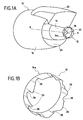
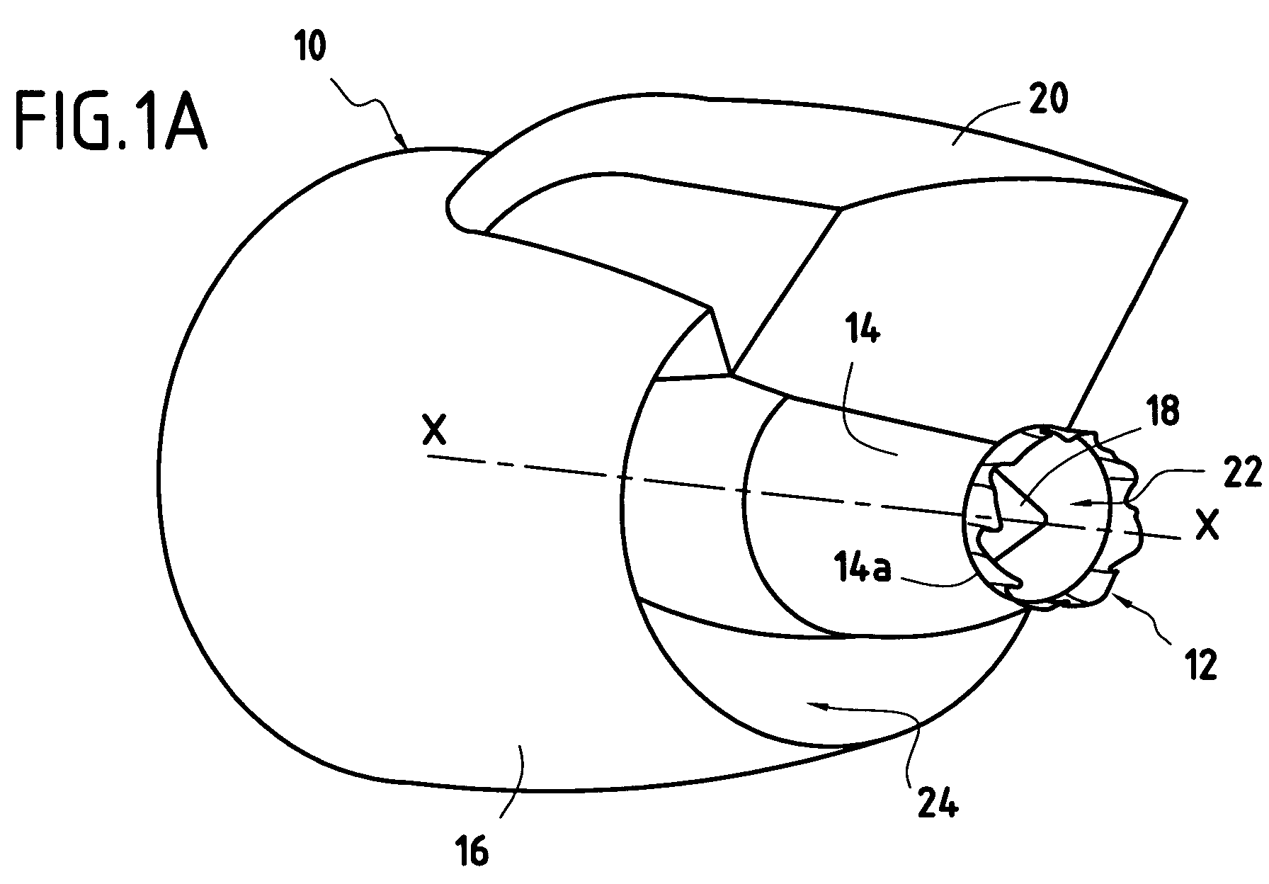
- FIG. 1A represents, in perspective, a nozzle 10 of FIG. turbomachine equipped with a device for reducing jet noise 12 according to the invention.
- the nozzle 10 axially symmetrical with respect to an axis longitudinal X-X of the turbomachine, is typically formed of a hood primary 14, a secondary cover 16 and a central body 18.
- the central body 18 is arranged concentrically inside the primary cover 14 and ends with a substantially conical portion.
- the downstream end 14a of the primary cover 14 extends beyond the conical portion of the central body 18.
- the secondary cover 16 also of substantially cylindrical or frustoconical shape, surrounds concentrically the primary cover 14.
- the nozzle thus defined is fixed under an airplane wing (not shown in the figures) via a support pylon 20.
- the concentric assembly of the elements of the nozzle 10 allows define: on the one hand, between the primary cover 14 and the central body 18, a first annular passage 22 for the flow of a gas stream from the turbomachine (called primary flow), and secondly, between the hoods primary 14 and secondary 16, a second annular passage 24 for the flow of air from the turbomachine (called secondary flow).
- primary flow a gas stream from the turbomachine
- secondary flow a second annular passage 24 for the flow of air from the turbomachine
- the central body 18 of the nozzle 10 is of internal type, that is to say that the downstream end 14a of the hood primary 14 extends longitudinally beyond the trailing edge of the body central.
- the jet noise reduction device according to the invention can also be applied to an external type nozzle of which the trailing edge of the central body extends beyond the downstream end of the primary hood.
- the nozzle 10 comprises a device for reducing the jet noise 12 formed of a plurality of corrugations 26 disposed in the extension of the downstream end 14a of the primary cover 14 and a plurality of notches 28 arranged between two corrugations successive ones of the plurality of corrugations so as to generate shear radial and tangential shear between primary and secondary flows from the turbomachine (Figure 1B).
- the corrugations 26 formed at the downstream end 14a of the hood 14 extend along the longitudinal axis X-X of the turbine engine. On the exemplary embodiment illustrated in FIG. 1B, they are each twisted between their upstream and downstream ends so as to extend radially inwards and outwards with respect to the downstream end 14a of the primary cover.
- the notches 28 are presented in the form of notches or cuts that extend substantially longitudinally between two successive corrugations 26.
- the corrugations 26 and the indentations 28 thus make it possible to generate radial shear and tangential shear between flows primary and secondary so as to increase the mixing between flows and therefore to reduce the jet noise.
- Radial shear means that this one is made in a radial direction with respect to the shape substantially cylindrical primary cover.
- shear tangential it must be understood that it is operated in one direction tangential to the substantially cylindrical shape of the hood primary.
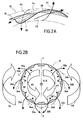
- FIG. 2A illustrates this phenomenon of radial shears and tangential.
- a waveform 26 and a notch 28 of the jet noise reduction device 12 according to the invention applied to a primary nozzle cover 14.
- Arrows in arrows plots illustrate the flow direction of the internal flow to the device at near the ripple 26 and the notch 28, while the arrows in dashed lines schematize the direction of flow of the external flow to the device in the vicinity of these same undulation and indentation.
- the internal flow flowing at neighborhood of it is directed, to be mixed with the external flow, both in a radial direction (arrow F1) and in a tangential direction (arrow F2).
- the radial and tangential flow directions of the flow are due to the fact that the undulation is twisted radially towards the outside relative to the primary cover 14.
- the external flow flowing in the vicinity of it is directed, to be mixed with the flow internally, both in a radial direction (arrow F3) and according to a tangential direction (arrow F4). So, it operates at the downstream end of primary cover between internal and external flow, radial shear between the flows schematized by arrows F1 and F3 and a tangential shear between flows schematized by arrows F2 and F4.
- plurality of corrugations 26 and the plurality of notches 28 of the reduction device of the jet noise 12 are asymmetrical with respect to at least one axis perpendicular to the longitudinal axis X-X of the turbomachine so as to generate a double counter-rotating effect between the internal and external flows at jet noise reduction device.
- the corrugations 26 and the indentations 28 of the primary cover are asymmetrical with respect to a transverse axis Y-Y. This asymmetry has the effect of generating a double effect contrarotative between internal and external flows.
- the internal flow mixes with the flow in the direction illustrated by the arrows 32a.
- This direction of created mixture for the internal flow, a general rotation F5 in the direction reverse rotation of the hands of a watch.
- the external flow mixes with the internal flow in the direction illustrated by the arrows 34a.
- This mixing direction generates, for the external flow, a rotation general F6 in the direction of clockwise rotation.
- the flows internal and external are therefore contrarotative.
- the internal flow mixing with the external flow in the direction illustrated by the arrows 32b This mixing direction creates, for the internal flow, a rotation F7 in the direction of rotation of the hands of a watch. As to external flow, it mixes with the internal flow in the direction of the arrows 34b. This mixing direction generates for it a rotation general F8 in the opposite direction of clockwise rotation, that is to say in the opposite direction of rotation F7 of the internal flow.
- the undulations and notches of the jet noise reduction device have a plurality of dissymmetries with respect to several axes perpendicular to the longitudinal axis X-X of the nozzle so as to multiply the double effects counter-rotating between internal and external flows.
- the shape and number of undulations and notches of the noise reduction device according to the invention may vary.
- the penetration height in the internal flows and external ripples is not limited.
- FIGS. 3A, 3B and 3C represent, in longitudinal section, other embodiments of the jet noise reduction device according to the invention.
- undulations 26 and notches 28 of the jet noise reduction device according to the invention should keep soft and rounded shapes and not penetrate way too important in the internal and external flows.
- FIG. 1A the device for reducing jet noise according to the invention is applied to the primary cover 14 of the nozzle 10.
- Figure 4 thus illustrates a turbomachine nozzle 10 whose secondary cover 16 is provided, at its downstream end 16a, of a jet noise reduction device 12.
- this device consists of a plurality of corrugations 26 arranged in the extension of the downstream end 16a of the secondary cover 16 and a plurality of indentations 28 arranged between two successive corrugations. It should be noted, however, that it is planned to provide at the level of the fixing the pylon 20 on the secondary cover, an interval 30 with no undulations or indentations to allow the fixation of the pylon 20.
- these corrugations 26 and notches 28 allow to generate a radial shear and a tangential shear between the secondary flow from the turbomachine and the flow of air flowing along the outer wall 16b of the secondary hood 16 in order to increase the mixing between the flows and thus to reduce the noise of jet.
- a device for reducing the noise can be implanted both on the primary hood and on the secondary hood.
- these devices make it possible to generate radial shears and tangential shears both between the stream primary and the secondary flow and between the secondary flow and the air flow flowing along the outer wall of the secondary cover.
Landscapes
- Engineering & Computer Science (AREA)
- Chemical & Material Sciences (AREA)
- Combustion & Propulsion (AREA)
- Mechanical Engineering (AREA)
- General Engineering & Computer Science (AREA)
- Structures Of Non-Positive Displacement Pumps (AREA)
- Turbine Rotor Nozzle Sealing (AREA)
- Supercharger (AREA)
- Motor Or Generator Cooling System (AREA)
- Exhaust Silencers (AREA)
Abstract
Description
- les figures 1A et 1B sont des vues en perspective d'un dispositif de réduction du bruit de jet selon l'invention équipant une tuyère de turbomachine ;
- les figures 2A et 2B sont des vues illustrant les effets de cisaillements et le double effet contrarotatif engendrés par un dispositif de réduction du bruit de jet selon l'invention ;
- les figures 3A, 3B et 3C sont des vues en coupe longitudinale de dispositifs de réduction du bruit de jet selon d'autres variantes de l'invention ; et
- la figure 4 est une vue en perspective d'une tuyère de turbomachine équipée d'un dispositif de réduction du bruit de jet selon une variante de l'invention.
Claims (4)
- Dispositif de réduction du bruit de jet d'une turbomachine, ladite turbomachine ayant un axe longitudinal (X-X) et comportant une tuyère (10) sensiblement cylindrique s'étendant selon ledit axe longitudinal de la turbomachine et ayant une extrémité aval pour le mélange de flux gazeux internes et externes à ladite tuyère, ledit dispositif comportant une pluralité d'ondulations (26) disposées dans le prolongement de l'extrémité aval de la tuyère (10) et une pluralité d'échancrures (28) disposées entre deux ondulations successives de ladite pluralité d'ondulations (26), caractérisé en ce que ladite pluralité d'ondulations et ladite pluralité d'échancrures sont dissymétriques par rapport à au moins un axe (Y-Y) perpendiculaire audit axe longitudinal (X-X) de la turbomachine de façon à générer un double effet contrarotatif entre lesdits flux gazeux.
- Tuyère (10) de turbomachine comportant :caractérisé en ce que ledit capot primaire (14) comporte, à une extrémité aval (14a), un dispositif de réduction de bruit (12) selon la revendication 1 de façon à générer un cisaillement radial et un cisaillement tangentiel entre lesdits flux primaire et secondaire.un capot primaire (14) s'étendant selon un axe longitudinal (X-X) de ladite tuyère,un corps central (18) disposé concentriquement à l'intérieur dudit capot primaire (16) afin de définir, entre ledit capot primaire et ledit corps central, un premier canal annulaire (22) pour l'écoulement d'un flux primaire, etun capot secondaire (16) entourant concentriquement ledit capot primaire (14) afin de définir un second canal annulaire (24) pour l'écoulement d'un flux secondaire,
- Tuyère (10) de turbomachine comportant :caractérisé en ce que ledit capot secondaire (16) comporte, à son extrémité aval (16a), un dispositif de réduction de bruit (12) selon la revendication 1 de façon à générer un cisaillement radial et un cisaillement tangentiel entre ledit flux secondaire et un flux d'air s'écoulant le long d'une paroi externe (16b) dudit capot secondaire (16).un capot primaire (14) s'étendant selon un axe longitudinal (X-X) de ladite tuyère,un corps central (18) disposé concentriquement à l'intérieur dudit capot primaire (14) afin de définir, entre ledit capot primaire et ledit corps central, un premier canal annulaire (22) pour l'écoulement d'un flux primaire, etun capot secondaire (16) entourant concentriquement ledit capot primaire (16) afin de définir un second canal annulaire (24) pour l'écoulement d'un flux secondaire,
- Tuyère (10) de turbomachine comportant :caractérisé en ce que ledit capot primaire (14) et ledit capot secondaire (16) comportent chacun à une extrémité aval (14a, 16a) un dispositif de réduction de bruit (12) selon la revendication 1 de façon à générer un cisaillement radial et un cisaillement tangentiel entre lesdits flux primaire et secondaire et entre ledit flux secondaire et un flux d'air s'écoulant le long d'une paroi externe (16b) dudit capot secondaire (16).un capot primaire (14) s'étendant selon un axe longitudinal (X-X) de ladite tuyère,un corps central (18) disposé concentriquement à l'intérieur dudit capot primaire (16) afin de définir, entre ledit capot primaire et ledit corps central, un premier canal annulaire (22) pour l'écoulement d'un flux primaire, etun capot secondaire (16) entourant concentriquement ledit capot primaire (14) afin de définir un second canal annulaire (24) pour l'écoulement d'un flux secondaire,
Applications Claiming Priority (2)
| Application Number | Priority Date | Filing Date | Title |
|---|---|---|---|
| FR0308383A FR2857416B1 (fr) | 2003-07-09 | 2003-07-09 | Dispositif de reduction du bruit de jet d'une turbomachine |
| FR0308383 | 2003-07-09 |
Publications (2)
| Publication Number | Publication Date |
|---|---|
| EP1496238A1 true EP1496238A1 (fr) | 2005-01-12 |
| EP1496238B1 EP1496238B1 (fr) | 2007-05-30 |
Family
ID=33443253
Family Applications (1)
| Application Number | Title | Priority Date | Filing Date |
|---|---|---|---|
| EP04291739A Expired - Lifetime EP1496238B1 (fr) | 2003-07-09 | 2004-07-08 | Dispositif de réduction de bruit de jet d'une turbomachine |
Country Status (10)
| Country | Link |
|---|---|
| US (1) | US7310939B2 (fr) |
| EP (1) | EP1496238B1 (fr) |
| JP (1) | JP4159519B2 (fr) |
| AT (1) | ATE363591T1 (fr) |
| CA (1) | CA2472935C (fr) |
| DE (1) | DE602004006673T2 (fr) |
| ES (1) | ES2286571T3 (fr) |
| FR (1) | FR2857416B1 (fr) |
| RU (1) | RU2004121800A (fr) |
| UA (1) | UA83992C2 (fr) |
Cited By (8)
| Publication number | Priority date | Publication date | Assignee | Title |
|---|---|---|---|---|
| EP1617068A1 (fr) * | 2004-07-13 | 2006-01-18 | Snecma Moteurs | Capot de tuyère de turbomachine à motifs à réduction de bruits de jet |
| EP1635043A1 (fr) * | 2004-09-10 | 2006-03-15 | Siemens Aktiengesellschaft | Turbine avec une alimentation de gaz secondaire |
| EP1752649A2 (fr) | 2005-08-10 | 2007-02-14 | United Technologies Corporation | Tuyère de turbine à gaz ayant un bord de fuite denté |
| FR2902837A1 (fr) * | 2006-06-26 | 2007-12-28 | Snecma Sa | Capot pour tuyere de turbomachine muni de motifs triangulaires a doubles sommets pour reduire le bruit de jet |
| EP2042721A1 (fr) * | 2007-09-28 | 2009-04-01 | Snecma | Capot pour tuyère de turbomachine à motifs pour la réduction de bruit de jet, tuyère et turbomachine associées |
| WO2009053554A1 (fr) * | 2007-08-14 | 2009-04-30 | Airbus France | Chevron anti-bruit pour tuyère, tuyère et turbomoteur pourvus d'un tel chevron |
| FR3061749A1 (fr) * | 2017-01-11 | 2018-07-13 | Safran Aircraft Engines | Melangeur de flux a epaisseur evolutive |
| FR3078098A1 (fr) * | 2018-02-16 | 2019-08-23 | Safran Aircraft Engines | Structure a profil en serrations inclinees |
Families Citing this family (15)
| Publication number | Priority date | Publication date | Assignee | Title |
|---|---|---|---|---|
| FR2896274B1 (fr) * | 2006-01-13 | 2008-04-18 | Snecma Sa | Melangeur de flux a section variable pour turboreacteur double flux d'avion supersonique |
| DE602007004260D1 (de) * | 2006-06-19 | 2010-03-04 | Snecma | Mischer für ein Doppelstromtriebwerk und entsprechende Düse und Strahltriebwerk |
| FR2902758B1 (fr) * | 2006-06-21 | 2009-04-10 | Airbus France Sas | Ensemble propulsif d'aeronef comportant un conduit d'ejection avec un bord de fuite echancre |
| FR2902836B1 (fr) | 2006-06-26 | 2008-10-24 | Snecma Sa | Capot pour tuyere de turbomachine muni de motifs triangulaires a point d'inflexion pour reduire le bruit de jet |
| US7966824B2 (en) | 2006-08-09 | 2011-06-28 | The Boeing Company | Jet engine nozzle exit configurations and associated systems and methods |
| US8157207B2 (en) * | 2006-08-09 | 2012-04-17 | The Boeing Company | Jet engine nozzle exit configurations, including projections oriented relative to pylons, and associated systems and methods |
| US7870722B2 (en) * | 2006-12-06 | 2011-01-18 | The Boeing Company | Systems and methods for passively directing aircraft engine nozzle flows |
| JP4830836B2 (ja) * | 2006-12-18 | 2011-12-07 | 株式会社Ihi | ジェット噴流排気ノズル及びジェットエンジン |
| US7966826B2 (en) * | 2007-02-14 | 2011-06-28 | The Boeing Company | Systems and methods for reducing noise from jet engine exhaust |
| FR2930972B1 (fr) * | 2008-05-07 | 2012-11-30 | Airbus France | Turbomachine a double flux pour aeronef a emission de bruit reduite |
| US8505310B2 (en) | 2008-10-22 | 2013-08-13 | General Electric Company | Gas turbine ejector and method of operation |
| JP5481946B2 (ja) * | 2009-06-05 | 2014-04-23 | 株式会社Ihi | 騒音低減装置 |
| RU2413161C1 (ru) * | 2009-12-28 | 2011-02-27 | Открытое акционерное общество "Научно-производственное объединение "Сатурн" (ОАО "НПО "Сатурн") | Устройство для снижения инфракрасной и радиолокационной заметности газотурбинного двигателя |
| GB201003497D0 (en) * | 2010-03-03 | 2010-04-14 | Rolls Royce Plc | Flow mixer |
| US8635875B2 (en) | 2010-04-29 | 2014-01-28 | Pratt & Whitney Canada Corp. | Gas turbine engine exhaust mixer including circumferentially spaced-apart radial rows of tabs extending downstream on the radial walls, crests and troughs |
Citations (6)
| Publication number | Priority date | Publication date | Assignee | Title |
|---|---|---|---|---|
| US4401269A (en) * | 1980-09-26 | 1983-08-30 | United Technologies Corporation | Lobe mixer for gas turbine engine |
| US4576002A (en) * | 1983-09-14 | 1986-03-18 | Rolls-Royce Limited | Exhaust mixer for turbofan aeroengine |
| US6082635A (en) * | 1996-06-12 | 2000-07-04 | The United States Of America As Represented By The Administrator Of The National Aeronautics And Space Administration | Undulated nozzle for enhanced exit area mixing |
| WO2000040851A1 (fr) * | 1999-01-04 | 2000-07-13 | Allison Advanced Development Company | Melangeur des gaz d'echappement et appareil l'utilisant |
| EP1160439A1 (fr) * | 2000-05-05 | 2001-12-05 | The Boeing Company | Mélangeur de flux pour turboréacteur |
| US20020178711A1 (en) * | 2001-05-31 | 2002-12-05 | Steven Martens | Truncated chevron exhaust nozzle |
Family Cites Families (4)
| Publication number | Priority date | Publication date | Assignee | Title |
|---|---|---|---|---|
| US3161257A (en) * | 1959-05-01 | 1964-12-15 | Young Alec David | Jet pipe nozzle silencers |
| US3568792A (en) * | 1969-06-18 | 1971-03-09 | Rohr Corp | Sound-suppressing and thrust-reversing apparatus |
| US6578355B1 (en) * | 1999-03-05 | 2003-06-17 | Rolls-Royce Deutschland Ltd & Co Kg | Bloom mixer for a turbofan engine |
| US6640537B2 (en) * | 2000-12-18 | 2003-11-04 | Pratt & Whitney Canada Corp. | Aero-engine exhaust jet noise reduction assembly |
-
2003
- 2003-07-09 FR FR0308383A patent/FR2857416B1/fr not_active Expired - Fee Related
-
2004
- 2004-07-07 RU RU2004121800/06A patent/RU2004121800A/ru not_active Application Discontinuation
- 2004-07-08 ES ES04291739T patent/ES2286571T3/es not_active Expired - Lifetime
- 2004-07-08 DE DE602004006673T patent/DE602004006673T2/de not_active Expired - Lifetime
- 2004-07-08 EP EP04291739A patent/EP1496238B1/fr not_active Expired - Lifetime
- 2004-07-08 AT AT04291739T patent/ATE363591T1/de not_active IP Right Cessation
- 2004-07-08 UA UA20040705522A patent/UA83992C2/ru unknown
- 2004-07-08 CA CA2472935A patent/CA2472935C/fr not_active Expired - Lifetime
- 2004-07-09 JP JP2004203106A patent/JP4159519B2/ja not_active Expired - Lifetime
- 2004-07-09 US US10/887,222 patent/US7310939B2/en not_active Expired - Lifetime
Patent Citations (6)
| Publication number | Priority date | Publication date | Assignee | Title |
|---|---|---|---|---|
| US4401269A (en) * | 1980-09-26 | 1983-08-30 | United Technologies Corporation | Lobe mixer for gas turbine engine |
| US4576002A (en) * | 1983-09-14 | 1986-03-18 | Rolls-Royce Limited | Exhaust mixer for turbofan aeroengine |
| US6082635A (en) * | 1996-06-12 | 2000-07-04 | The United States Of America As Represented By The Administrator Of The National Aeronautics And Space Administration | Undulated nozzle for enhanced exit area mixing |
| WO2000040851A1 (fr) * | 1999-01-04 | 2000-07-13 | Allison Advanced Development Company | Melangeur des gaz d'echappement et appareil l'utilisant |
| EP1160439A1 (fr) * | 2000-05-05 | 2001-12-05 | The Boeing Company | Mélangeur de flux pour turboréacteur |
| US20020178711A1 (en) * | 2001-05-31 | 2002-12-05 | Steven Martens | Truncated chevron exhaust nozzle |
Cited By (17)
| Publication number | Priority date | Publication date | Assignee | Title |
|---|---|---|---|---|
| EP1617068A1 (fr) * | 2004-07-13 | 2006-01-18 | Snecma Moteurs | Capot de tuyère de turbomachine à motifs à réduction de bruits de jet |
| EP1635043A1 (fr) * | 2004-09-10 | 2006-03-15 | Siemens Aktiengesellschaft | Turbine avec une alimentation de gaz secondaire |
| EP1752649A3 (fr) * | 2005-08-10 | 2010-03-24 | United Technologies Corporation | Tuyère de turbine à gaz ayant un bord de fuite denté |
| EP1752649A2 (fr) | 2005-08-10 | 2007-02-14 | United Technologies Corporation | Tuyère de turbine à gaz ayant un bord de fuite denté |
| EP2568151A3 (fr) * | 2005-08-10 | 2013-11-06 | United Technologies Corporation | Tuyère de turbine à gaz avec bord de fuite denté |
| EP1873388A1 (fr) * | 2006-06-26 | 2008-01-02 | Snecma | Capot pour tuyère de turbomachine muni de motifs triangulaires à doubles sommets pour réduire le bruit de jet |
| FR2902837A1 (fr) * | 2006-06-26 | 2007-12-28 | Snecma Sa | Capot pour tuyere de turbomachine muni de motifs triangulaires a doubles sommets pour reduire le bruit de jet |
| WO2009053554A1 (fr) * | 2007-08-14 | 2009-04-30 | Airbus France | Chevron anti-bruit pour tuyère, tuyère et turbomoteur pourvus d'un tel chevron |
| CN101809272B (zh) * | 2007-08-14 | 2013-09-04 | 空中客车运营简化股份公司 | 用于尾喷管的抗噪v形尾缘、具有这种v形尾缘的尾喷管和涡轮发动机 |
| FR2921700A1 (fr) * | 2007-09-28 | 2009-04-03 | Snecma Sa | Capot pour tuyere de turbomachine a motifs a reduction de bruit de jet |
| EP2042721A1 (fr) * | 2007-09-28 | 2009-04-01 | Snecma | Capot pour tuyère de turbomachine à motifs pour la réduction de bruit de jet, tuyère et turbomachine associées |
| FR3061749A1 (fr) * | 2017-01-11 | 2018-07-13 | Safran Aircraft Engines | Melangeur de flux a epaisseur evolutive |
| WO2018130787A1 (fr) * | 2017-01-11 | 2018-07-19 | Safran Aircraft Engines | Mélangeur de flux à épaisseur évolutive |
| US11506143B2 (en) * | 2017-01-11 | 2022-11-22 | Safran Aircraft Engines | Flow mixer with a changing thickness |
| FR3078098A1 (fr) * | 2018-02-16 | 2019-08-23 | Safran Aircraft Engines | Structure a profil en serrations inclinees |
| US11629664B2 (en) | 2018-02-16 | 2023-04-18 | Safran Aircraft Engines | Turbine engine with a flow splitter having a profile with inclined serrations |
| US11913405B2 (en) | 2018-02-16 | 2024-02-27 | Safran Aircraft Engines | Turbine engine with a flow splitter having a profile with inclined serrations |
Also Published As
| Publication number | Publication date |
|---|---|
| EP1496238B1 (fr) | 2007-05-30 |
| FR2857416B1 (fr) | 2007-05-25 |
| FR2857416A1 (fr) | 2005-01-14 |
| ATE363591T1 (de) | 2007-06-15 |
| ES2286571T3 (es) | 2007-12-01 |
| DE602004006673T2 (de) | 2008-02-07 |
| US20050115245A1 (en) | 2005-06-02 |
| CA2472935C (fr) | 2012-06-26 |
| US7310939B2 (en) | 2007-12-25 |
| UA83992C2 (ru) | 2008-09-10 |
| DE602004006673D1 (de) | 2007-07-12 |
| RU2004121800A (ru) | 2006-01-10 |
| JP4159519B2 (ja) | 2008-10-01 |
| JP2005030404A (ja) | 2005-02-03 |
| CA2472935A1 (fr) | 2005-01-09 |
Similar Documents
| Publication | Publication Date | Title |
|---|---|---|
| CA2472935C (fr) | Dispositif de reduction du bruit de jet d'une turbomachine | |
| EP1482160B1 (fr) | Tuyère de turbomachine à réduction de bruit | |
| CA2594753C (fr) | Tuyere d'ejection des gaz pour turbomachine a double flux ayant une section d'ejection ou de col variable par deplacement du capot secondaire | |
| EP2179163B1 (fr) | Chevron pour tuyère, tuyère et turbomoteur associés | |
| EP2257704B1 (fr) | Dispositif de réduction du bruit généré par un réacteur d'aéronef à jets de fluide de même orientation | |
| EP1870588A1 (fr) | Mélangeur à mouvement giratoire pour tuyère à flux confluents de turbomachine | |
| CA2592484C (fr) | Capot pour tuyere de turbomachine muni de motifs triangulaires a doubles sommets pour reduire le bruit de jet | |
| EP3295009B1 (fr) | Mélangeur à lobes avec écopes | |
| EP1870589A1 (fr) | Mélangeur à lobes courbes pour tuyère à flux confluents de turbomachine | |
| CA2511892C (fr) | Capot pour tuyere de turbomachine a motifs a reduction de bruit de jet | |
| FR2938502A1 (fr) | Turbomachine comportant une helice non carenee equipee de moyens de guidage d'air | |
| EP3839238B1 (fr) | Cône de sortie d'un ensemble propulsif d'aéronef formant un système de traitement acoustique à au moins deux degrés de liberté | |
| EP1873389A1 (fr) | Capot pour tuyère de turbomachine muni de motifs triangulaires à point d'inflexion pour réduire le bruit de jet | |
| FR2971015A1 (fr) | Tuyere d'ejection pour turboreacteur d'avion a double flux separes a capot secondaire deployable et corps central retractable | |
| CA2640236A1 (fr) | Capot pour tuyere de turbomachine a motifs a reduction de bruit de jet | |
| EP3044450B1 (fr) | Arrière corps de turboréacteur comportant une tuyère équipée d'un système d'inversion de poussée qui intègre une couronne de chevrons antibruit | |
| EP2297445A1 (fr) | Turbomoteur à double flux pour aéronef à émission de bruit réduite | |
| WO2010133780A1 (fr) | Capot pour tuyere de turbomachine muni de motifs a ailettes laterales pour reduire le bruit de jet | |
| CA2980794A1 (fr) | Dispositif a grilles d'ejection de microjets pour la reduction du bruit de jet d'une turbomachine | |
| FR2902468A1 (fr) | Melangeur a lobes munis de motifs pour tuyere a flux confluents de turbomachine | |
| FR3034142A1 (fr) | Dispositif a grilles d'ejection de microjets pour la reduction du bruit de jet d'une turbomachine | |
| FR2986833A1 (fr) | Procede pour definir des chevrons dans un capot d'une tuyere de turbomachine et capot pour une tuyere de turbomachine correspondant |
Legal Events
| Date | Code | Title | Description |
|---|---|---|---|
| PUAI | Public reference made under article 153(3) epc to a published international application that has entered the european phase |
Free format text: ORIGINAL CODE: 0009012 |
|
| 17P | Request for examination filed |
Effective date: 20040714 |
|
| AK | Designated contracting states |
Kind code of ref document: A1 Designated state(s): AT BE BG CH CY CZ DE DK EE ES FI FR GB GR HU IE IT LI LU MC NL PL PT RO SE SI SK TR |
|
| AX | Request for extension of the european patent |
Extension state: AL HR LT LV MK |
|
| RAP1 | Party data changed (applicant data changed or rights of an application transferred) |
Owner name: SNECMA |
|
| AKX | Designation fees paid |
Designated state(s): AT BE BG CH CY CZ DE DK EE ES FI FR GB GR HU IE IT LI LU MC NL PL PT RO SE SI SK TR |
|
| GRAP | Despatch of communication of intention to grant a patent |
Free format text: ORIGINAL CODE: EPIDOSNIGR1 |
|
| GRAS | Grant fee paid |
Free format text: ORIGINAL CODE: EPIDOSNIGR3 |
|
| GRAA | (expected) grant |
Free format text: ORIGINAL CODE: 0009210 |
|
| AK | Designated contracting states |
Kind code of ref document: B1 Designated state(s): AT BE BG CH CY CZ DE DK EE ES FI FR GB GR HU IE IT LI LU MC NL PL PT RO SE SI SK TR |
|
| PG25 | Lapsed in a contracting state [announced via postgrant information from national office to epo] |
Ref country code: FI Free format text: LAPSE BECAUSE OF FAILURE TO SUBMIT A TRANSLATION OF THE DESCRIPTION OR TO PAY THE FEE WITHIN THE PRESCRIBED TIME-LIMIT Effective date: 20070530 |
|
| REG | Reference to a national code |
Ref country code: GB Ref legal event code: FG4D Free format text: NOT ENGLISH |
|
| REG | Reference to a national code |
Ref country code: CH Ref legal event code: EP |
|
| REG | Reference to a national code |
Ref country code: IE Ref legal event code: FG4D Free format text: LANGUAGE OF EP DOCUMENT: FRENCH |
|
| REF | Corresponds to: |
Ref document number: 602004006673 Country of ref document: DE Date of ref document: 20070712 Kind code of ref document: P |
|
| REG | Reference to a national code |
Ref country code: SE Ref legal event code: TRGR |
|
| GBT | Gb: translation of ep patent filed (gb section 77(6)(a)/1977) |
Effective date: 20070822 |
|
| PG25 | Lapsed in a contracting state [announced via postgrant information from national office to epo] |
Ref country code: PL Free format text: LAPSE BECAUSE OF FAILURE TO SUBMIT A TRANSLATION OF THE DESCRIPTION OR TO PAY THE FEE WITHIN THE PRESCRIBED TIME-LIMIT Effective date: 20070530 Ref country code: AT Free format text: LAPSE BECAUSE OF FAILURE TO SUBMIT A TRANSLATION OF THE DESCRIPTION OR TO PAY THE FEE WITHIN THE PRESCRIBED TIME-LIMIT Effective date: 20070530 |
|
| REG | Reference to a national code |
Ref country code: ES Ref legal event code: FG2A Ref document number: 2286571 Country of ref document: ES Kind code of ref document: T3 |
|
| NLV1 | Nl: lapsed or annulled due to failure to fulfill the requirements of art. 29p and 29m of the patents act | ||
| REG | Reference to a national code |
Ref country code: IE Ref legal event code: FD4D |
|
| BERE | Be: lapsed |
Owner name: SNECMA Effective date: 20070731 |
|
| PG25 | Lapsed in a contracting state [announced via postgrant information from national office to epo] |
Ref country code: IE Free format text: LAPSE BECAUSE OF FAILURE TO SUBMIT A TRANSLATION OF THE DESCRIPTION OR TO PAY THE FEE WITHIN THE PRESCRIBED TIME-LIMIT Effective date: 20070530 Ref country code: BG Free format text: LAPSE BECAUSE OF FAILURE TO SUBMIT A TRANSLATION OF THE DESCRIPTION OR TO PAY THE FEE WITHIN THE PRESCRIBED TIME-LIMIT Effective date: 20070830 Ref country code: PT Free format text: LAPSE BECAUSE OF FAILURE TO SUBMIT A TRANSLATION OF THE DESCRIPTION OR TO PAY THE FEE WITHIN THE PRESCRIBED TIME-LIMIT Effective date: 20071030 Ref country code: DK Free format text: LAPSE BECAUSE OF FAILURE TO SUBMIT A TRANSLATION OF THE DESCRIPTION OR TO PAY THE FEE WITHIN THE PRESCRIBED TIME-LIMIT Effective date: 20070530 Ref country code: SI Free format text: LAPSE BECAUSE OF FAILURE TO SUBMIT A TRANSLATION OF THE DESCRIPTION OR TO PAY THE FEE WITHIN THE PRESCRIBED TIME-LIMIT Effective date: 20070530 Ref country code: NL Free format text: LAPSE BECAUSE OF FAILURE TO SUBMIT A TRANSLATION OF THE DESCRIPTION OR TO PAY THE FEE WITHIN THE PRESCRIBED TIME-LIMIT Effective date: 20070530 |
|
| PG25 | Lapsed in a contracting state [announced via postgrant information from national office to epo] |
Ref country code: SK Free format text: LAPSE BECAUSE OF FAILURE TO SUBMIT A TRANSLATION OF THE DESCRIPTION OR TO PAY THE FEE WITHIN THE PRESCRIBED TIME-LIMIT Effective date: 20070530 |
|
| PLBE | No opposition filed within time limit |
Free format text: ORIGINAL CODE: 0009261 |
|
| STAA | Information on the status of an ep patent application or granted ep patent |
Free format text: STATUS: NO OPPOSITION FILED WITHIN TIME LIMIT |
|
| PG25 | Lapsed in a contracting state [announced via postgrant information from national office to epo] |
Ref country code: MC Free format text: LAPSE BECAUSE OF NON-PAYMENT OF DUE FEES Effective date: 20070731 Ref country code: GR Free format text: LAPSE BECAUSE OF FAILURE TO SUBMIT A TRANSLATION OF THE DESCRIPTION OR TO PAY THE FEE WITHIN THE PRESCRIBED TIME-LIMIT Effective date: 20070831 |
|
| 26N | No opposition filed |
Effective date: 20080303 |
|
| PG25 | Lapsed in a contracting state [announced via postgrant information from national office to epo] |
Ref country code: RO Free format text: LAPSE BECAUSE OF FAILURE TO SUBMIT A TRANSLATION OF THE DESCRIPTION OR TO PAY THE FEE WITHIN THE PRESCRIBED TIME-LIMIT Effective date: 20070530 |
|
| PG25 | Lapsed in a contracting state [announced via postgrant information from national office to epo] |
Ref country code: BE Free format text: LAPSE BECAUSE OF NON-PAYMENT OF DUE FEES Effective date: 20070731 |
|
| PG25 | Lapsed in a contracting state [announced via postgrant information from national office to epo] |
Ref country code: EE Free format text: LAPSE BECAUSE OF FAILURE TO SUBMIT A TRANSLATION OF THE DESCRIPTION OR TO PAY THE FEE WITHIN THE PRESCRIBED TIME-LIMIT Effective date: 20070530 |
|
| REG | Reference to a national code |
Ref country code: CH Ref legal event code: PL |
|
| PG25 | Lapsed in a contracting state [announced via postgrant information from national office to epo] |
Ref country code: CH Free format text: LAPSE BECAUSE OF NON-PAYMENT OF DUE FEES Effective date: 20080731 Ref country code: LI Free format text: LAPSE BECAUSE OF NON-PAYMENT OF DUE FEES Effective date: 20080731 |
|
| PG25 | Lapsed in a contracting state [announced via postgrant information from national office to epo] |
Ref country code: CY Free format text: LAPSE BECAUSE OF FAILURE TO SUBMIT A TRANSLATION OF THE DESCRIPTION OR TO PAY THE FEE WITHIN THE PRESCRIBED TIME-LIMIT Effective date: 20070530 |
|
| PG25 | Lapsed in a contracting state [announced via postgrant information from national office to epo] |
Ref country code: LU Free format text: LAPSE BECAUSE OF NON-PAYMENT OF DUE FEES Effective date: 20070708 |
|
| PG25 | Lapsed in a contracting state [announced via postgrant information from national office to epo] |
Ref country code: HU Free format text: LAPSE BECAUSE OF FAILURE TO SUBMIT A TRANSLATION OF THE DESCRIPTION OR TO PAY THE FEE WITHIN THE PRESCRIBED TIME-LIMIT Effective date: 20071201 Ref country code: TR Free format text: LAPSE BECAUSE OF FAILURE TO SUBMIT A TRANSLATION OF THE DESCRIPTION OR TO PAY THE FEE WITHIN THE PRESCRIBED TIME-LIMIT Effective date: 20070530 |
|
| PGFP | Annual fee paid to national office [announced via postgrant information from national office to epo] |
Ref country code: ES Payment date: 20120716 Year of fee payment: 9 |
|
| REG | Reference to a national code |
Ref country code: ES Ref legal event code: FD2A Effective date: 20150406 |
|
| PG25 | Lapsed in a contracting state [announced via postgrant information from national office to epo] |
Ref country code: ES Free format text: LAPSE BECAUSE OF NON-PAYMENT OF DUE FEES Effective date: 20130709 |
|
| REG | Reference to a national code |
Ref country code: FR Ref legal event code: PLFP Year of fee payment: 13 |
|
| REG | Reference to a national code |
Ref country code: FR Ref legal event code: PLFP Year of fee payment: 14 |
|
| REG | Reference to a national code |
Ref country code: FR Ref legal event code: CD Owner name: SAFRAN AIRCRAFT ENGINES Effective date: 20170719 |
|
| REG | Reference to a national code |
Ref country code: FR Ref legal event code: PLFP Year of fee payment: 15 |
|
| REG | Reference to a national code |
Ref country code: DE Ref legal event code: R082 Ref document number: 602004006673 Country of ref document: DE Representative=s name: CBDL PATENTANWAELTE GBR, DE |
|
| PGFP | Annual fee paid to national office [announced via postgrant information from national office to epo] |
Ref country code: IT Payment date: 20230620 Year of fee payment: 20 Ref country code: FR Payment date: 20230621 Year of fee payment: 20 Ref country code: CZ Payment date: 20230623 Year of fee payment: 20 |
|
| PGFP | Annual fee paid to national office [announced via postgrant information from national office to epo] |
Ref country code: SE Payment date: 20230622 Year of fee payment: 20 |
|
| PGFP | Annual fee paid to national office [announced via postgrant information from national office to epo] |
Ref country code: GB Payment date: 20230620 Year of fee payment: 20 |
|
| PGFP | Annual fee paid to national office [announced via postgrant information from national office to epo] |
Ref country code: DE Payment date: 20230620 Year of fee payment: 20 |
|
| REG | Reference to a national code |
Ref country code: DE Ref legal event code: R071 Ref document number: 602004006673 Country of ref document: DE |
|
| PG25 | Lapsed in a contracting state [announced via postgrant information from national office to epo] |
Ref country code: CZ Free format text: LAPSE BECAUSE OF EXPIRATION OF PROTECTION Effective date: 20240708 |
|
| PG25 | Lapsed in a contracting state [announced via postgrant information from national office to epo] |
Ref country code: CZ Free format text: LAPSE BECAUSE OF EXPIRATION OF PROTECTION Effective date: 20240708 |
|
| REG | Reference to a national code |
Ref country code: GB Ref legal event code: PE20 Expiry date: 20240707 |
|
| REG | Reference to a national code |
Ref country code: SE Ref legal event code: EUG |
|
| PG25 | Lapsed in a contracting state [announced via postgrant information from national office to epo] |
Ref country code: GB Free format text: LAPSE BECAUSE OF EXPIRATION OF PROTECTION Effective date: 20240707 |
|
| PG25 | Lapsed in a contracting state [announced via postgrant information from national office to epo] |
Ref country code: GB Free format text: LAPSE BECAUSE OF EXPIRATION OF PROTECTION Effective date: 20240707 |