EP1752649A2 - Tuyère de turbine à gaz ayant un bord de fuite denté - Google Patents
Tuyère de turbine à gaz ayant un bord de fuite denté Download PDFInfo
- Publication number
- EP1752649A2 EP1752649A2 EP06254093A EP06254093A EP1752649A2 EP 1752649 A2 EP1752649 A2 EP 1752649A2 EP 06254093 A EP06254093 A EP 06254093A EP 06254093 A EP06254093 A EP 06254093A EP 1752649 A2 EP1752649 A2 EP 1752649A2
- Authority
- EP
- European Patent Office
- Prior art keywords
- nozzle
- lobe
- trailing edges
- lobes
- trough
- Prior art date
- Legal status (The legal status is an assumption and is not a legal conclusion. Google has not performed a legal analysis and makes no representation as to the accuracy of the status listed.)
- Granted
Links
Images


Classifications
-
- F—MECHANICAL ENGINEERING; LIGHTING; HEATING; WEAPONS; BLASTING
- F02—COMBUSTION ENGINES; HOT-GAS OR COMBUSTION-PRODUCT ENGINE PLANTS
- F02K—JET-PROPULSION PLANTS
- F02K1/00—Plants characterised by the form or arrangement of the jet pipe or nozzle; Jet pipes or nozzles peculiar thereto
- F02K1/40—Nozzles having means for dividing the jet into a plurality of partial jets or having an elongated cross-section outlet
-
- F—MECHANICAL ENGINEERING; LIGHTING; HEATING; WEAPONS; BLASTING
- F02—COMBUSTION ENGINES; HOT-GAS OR COMBUSTION-PRODUCT ENGINE PLANTS
- F02K—JET-PROPULSION PLANTS
- F02K1/00—Plants characterised by the form or arrangement of the jet pipe or nozzle; Jet pipes or nozzles peculiar thereto
- F02K1/38—Introducing air inside the jet
- F02K1/386—Introducing air inside the jet mixing devices in the jet pipe, e.g. for mixing primary and secondary flow
-
- F—MECHANICAL ENGINEERING; LIGHTING; HEATING; WEAPONS; BLASTING
- F02—COMBUSTION ENGINES; HOT-GAS OR COMBUSTION-PRODUCT ENGINE PLANTS
- F02K—JET-PROPULSION PLANTS
- F02K1/00—Plants characterised by the form or arrangement of the jet pipe or nozzle; Jet pipes or nozzles peculiar thereto
- F02K1/46—Nozzles having means for adding air to the jet or for augmenting the mixing region between the jet and the ambient air, e.g. for silencing
-
- F—MECHANICAL ENGINEERING; LIGHTING; HEATING; WEAPONS; BLASTING
- F05—INDEXING SCHEMES RELATING TO ENGINES OR PUMPS IN VARIOUS SUBCLASSES OF CLASSES F01-F04
- F05D—INDEXING SCHEME FOR ASPECTS RELATING TO NON-POSITIVE-DISPLACEMENT MACHINES OR ENGINES, GAS-TURBINES OR JET-PROPULSION PLANTS
- F05D2250/00—Geometry
- F05D2250/60—Structure; Surface texture
- F05D2250/61—Structure; Surface texture corrugated
- F05D2250/611—Structure; Surface texture corrugated undulated
-
- F—MECHANICAL ENGINEERING; LIGHTING; HEATING; WEAPONS; BLASTING
- F05—INDEXING SCHEMES RELATING TO ENGINES OR PUMPS IN VARIOUS SUBCLASSES OF CLASSES F01-F04
- F05D—INDEXING SCHEME FOR ASPECTS RELATING TO NON-POSITIVE-DISPLACEMENT MACHINES OR ENGINES, GAS-TURBINES OR JET-PROPULSION PLANTS
- F05D2250/00—Geometry
- F05D2250/70—Shape
-
- F—MECHANICAL ENGINEERING; LIGHTING; HEATING; WEAPONS; BLASTING
- F05—INDEXING SCHEMES RELATING TO ENGINES OR PUMPS IN VARIOUS SUBCLASSES OF CLASSES F01-F04
- F05D—INDEXING SCHEME FOR ASPECTS RELATING TO NON-POSITIVE-DISPLACEMENT MACHINES OR ENGINES, GAS-TURBINES OR JET-PROPULSION PLANTS
- F05D2260/00—Function
- F05D2260/96—Preventing, counteracting or reducing vibration or noise
Definitions
- This invention relates to exhaust flow nozzles, such as those used in gas turbine engines, having serrations or undulations to reduce noise.
- the generation of noise from turbulent jet exhausts is of significant practical interest for low and moderate bypass ratio engines used in subsonic civil transports.
- the jet exhaust noise is one component of overall engine noise, and is particularly important at take-off and cutback conditions.
- the jet noise contribution is reduced, but it is still a factor especially with continually tightening of noise restrictions.
- Prior approaches to jet noise reduction have relied primarily on mixing enhancement, where the aim is to promote the exchange of momentum between the high-speed primary stream and the lower-momentum secondary flow (i.e. fan bypass and/or ambient flight stream).
- Tabs and chevron-type devices have been used for single stream and separate flow exhaust systems.
- Lobed mixers have been used for mixed-flow exhausts.
- a second shortcoming of external plume mixing devices is adverse impact on aerodynamic performance (axial thrust). Tabs and chevrons typically increase Total Specific Fuel Consumption (TSFC), and can adversely affect nozzle discharge characteristics at off-design points in the flight envelope.
- TSFC Total Specific Fuel Consumption
- the present invention relates to a nozzle for a gas turbine engine.
- the inventive undulations and serrations may be provided at the exit geometry of a core and/or fan exhaust flow nozzle.
- An annular wall defines a fluid flow passage and includes a base portion and an adjoining exit portion.
- the base portion is typically generally frustoconical in shape and includes an arcuate contour in the axial direction.
- the exit portion includes undulations in a generally radial direction that provide lobes and troughs with trailing edges.
- One of the lobe and trough trailing edges are recessed from the other of the lobe and trough trailing edges in a generally axial direction.
- the other of the lobe and trough trailing edges form apexes with the apexes provided on tabs.
- the troughs extend radially inward in the axial direction towards the trough trailing edges.
- geometries may be used to reduce noise to desired levels.
- the geometries are determined based upon the particular application and through mathematical modeling and empirical means.
- the invention is a means for reducing jet noise emission from gas turbine engine exhausts.
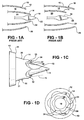
- Applications include fan and core nozzles of separate flow exhaust (Figure 1A) and common tailpipe nozzle of mixed flow (Figure 1B) exhaust configurations.
- Gas turbine engines 10 include a fan exhaust nozzle 12 that surrounds a core exhaust nozzle 14 to provide a fan exhaust fluid passage 16.
- a central body 18 is arranged within the core exhaust nozzle 14, which provides a core exhaust fluid passage 20.
- the tip 22 of the central body 18 can extend beyond a terminal end 24 of the core exhaust nozzle 14 (as shown in Fig. 1A) or be recessed.
- the terminal end 24 extends beyond a terminal end 26 of the fan exhaust nozzle 12 for a separate-flow configuration.
- the terminal end 24 is recessed from the terminal end 26 in a mixed-flow configuration, shown in Figure 1B.
- the core exhaust nozzle 14 includes an annular wall 28, which is typically circular in cross-section and frustoconical in shape when viewed from the side.
- the annular wall 28 includes a base portion 30.
- An exit portion 32 adjoins the base portion 30 and includes undulations 34.
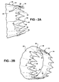
- a similar nozzle with a greater number of undulations is shown in Figures 2A and 2B.
- the nozzle trailing edge includes undulations 34 to produce a pattern of lobes 36 and troughs 38 around the nozzle perimeter.
- the geometry of the undulations 34 is selected to reduce noise in a desired range or ranges of frequencies.
- Figure 3A-7C Some example embodiments of the concept are illustrated in Figure 3A-7C. Beginning with Figures 1C, 2A and 2B, the lobes 36 are shown recessed from the troughs 38, although this can be reversed if desired.
- the lobes 36 and troughs 38 extend above and below an imaginary surface S that extends along generally the same contour of base portion 30 of the annular wall 28, best seen in Figure 1C and Figures 3B, 4B, 5B, 6B and 7B.
- Figure 1D illustrates fan exhaust and core nozzles 12 and 14 with the undulations 34.
- the number of undulations 34 or tabs 46 on the nozzles 12 and 14 are equal to one another.
- the lobes 36 are "clocked" or radially aligned with one another for improved acoustic performance characteristics.
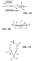
- lobe shapes and trailing-edge plan forms are shown in Figures 3A-7C.
- the lobe trailing edge 40 is recessed relative to the trough trailing edge 42 similar to Figures 2A and 2B.
- the lobes 36 extend radially a distance R from an axis A a height H1 above the imaginary surface S.
- the troughs 38 extend radially below the imaginary surface S by a height H2.
- the heights H1 and H2 are different when taken from the trailing edges 40, 42 as seen in the end view ( Figure 3B), the heights are generally equivalent when taken at a common axial position, which is best seen in Figure 3A.
- the undulations 34 are sinusoidal and have a spacing, or width, W. The height/width ratio is preferably less than 1.
- h/w 0.10 0.00 0.20
- Lobe Angle (deg) 14 to 18 0 26
- Max angle is about 1.56X larger than mean angle.
- Circumferential Lobe Contour Sinusoidal Square Steeper walls in circumferential direction creates more circulation, but more losses and higher concentrations of vorticity.
- Tab Shape sin ⁇ 0.5 Triangular; sharper than sin ⁇ 0.5 with larger base; rounded.
- Tab/Lobe Count 6 to 12 Tab Penetration Angle (deg) 2 to 4 0 9 Low angles are preferred to reduced high frequency penalty and thrust loss. High penetration provides higher circulation, gentle tabs have been found to be most effective for noise. With lobes to enhance circulation, tab penetration can be even less.
- the lobe angle, ⁇ is shown in Figure 2A.
- the axial lobe contour, which is provided on the lobe trailing edge 40, is shown in Figure 3C and is a cosine shape.
- the tab shape, which is provided on the trough trailing edge for geometries where the troughs provide the tabs ( Figure 3C), can be of a sinusoidal function, for example.
- the tab shape, or apex angle, may be very steep thereby forming a cusp. Any suitable lobe/trough count may be provided.
- the trough trailing edge 42 is recessed relative to the lobe trailing edge 40.
- Another variation is shown in Figures 5A-5C, and includes tabs 46 having curved apexes 48 having a terminal point 50 similar to the geometries shown in Figures 3A-4C.
- Figure 6A-7C have triangular-like tabs 46 that come to sharp points at their apexes.
- the tab penetration angle ⁇ is best shown in Figure 7A.
- the tab contour 54 may be parabolic to obtain a desired circulation.
- the length L of the tabs 46 relative to the recesses 44 may be selected as desired.
- the principle of operation is that the modified nozzle trailing edge introduces an axial component of vorticity in the jet plume by re-orienting circumferential vorticity.
- the axial vorticity induces radially outward motion in the downstream jet plume, promoting entrainment and mixing of low-momentum ambient flow into the high-speed jet stream. This in turn disrupts and attenuates large-scale turbulent structures in the plume, reducing low-frequency noise emission.
- the axial vorticity and associated mixing in the near-nozzle region typically causes parasitic noise at high frequencies, reducing the overall noise benefit.
- Another disadvantage to the introduction of an axial component of vorticity is the loss of thrust due to non-axial velocity components.
- this invention utilizes extra degrees of freedom enabled by a combined lobe-tab geometry (a three-dimensional nozzle contour).
- a judicious design of the nozzle trailing edge contouring creates an axial component of vorticity in a form that minimizes high-frequency noise and thrust penalty.
- the unique geometry enables modification of the size, strength, location, spacing and distribution of the induced axial vorticity that organizes into mixing structures in the plume. As a result, higher overall noise reduction is achieved with reduced penalty at the annoyance-weighted high frequencies.
- the nozzle trailing edge undulation and tab-like features provides additional design parameters to help achieve desired nozzle discharge characteristics (such as for choked convergent and convergent-divergent nozzles).
- features of this design are non-vertical lobe side walls, curvature of the trough edges, and curvature of the trough base or contour 54.
- the contouring, lobe shape, and ratio h / L are selected to balance the amount of vorticity shed from the lobe and trough regions, to avoid formation of high vorticity concentrations, and locate and/or space the centers of vorticity in an advantageous manner.
- the preferred lobe features such as shape and h/w ratio are distinct from prior art for lobed mixers in that the side-walls are substantially non-vertical (so as to avoid high concentrations of vorticity and mixing) and the h/w ratios are usually of order 1 or smaller, significantly lower than ratios of 4-6 characteristic of lobed mixers.
- Axial vorticity generated by this configuration was obtained using Reynolds-averaged Navier Stokes computations.
- FIG. 1C A second embodiment of the invention, applied to the core nozzle of a separate flow exhaust, is shown in Figure 1C.
- Reynolds-averaged Navier Stokes computations have shown that for separate flow exhausts, delaying interaction of the primary and secondary shear-layers reduces high-frequency mixing noise at a given level of circulation.
- the location where the turbulence levels are high for the undulated serrated nozzle of Figure 1C is farther downstream compared to that for the tab/chevron case.
- the flow field from the nozzle proposed in the present invention can be tailored to generate vorticity (centered closer to the tab-like protrusion) to promote radially-inward migration of the mixing structures and thereby delay of the core-fan and fan-ambient shear-layer interaction.
- the invention reduces high-frequency mixing noise penalty. Additional geometric parameters afforded by the invention enable tailoring the vorticity distribution to mitigate parasitic mixing noise. As a result, higher overall noise reduction is achieved. In particular, it has been shown that introducing tip-centered vorticity in the primary shear-layer of separate flow exhausts can reduce parasitic mixing noise by delaying interaction of the primary and secondary shear layers, as compared to conventional tab or chevron having vorticity centered closer to the tab/Chevron base.
- the invention reduces thrust penalty for a given level of shed circulation.
- the thrust penalty may be reduced relative to a tab with similar plan form and equal shed circulation.
- drag is reduced by 42%.
- the current concept provides a more efficient method for producing axial vorticity or effecting mixing.
- the improved efficiency is due to more effective use of the tab base region. Since the base is wider, it has larger potential for circulation generation.
- radial flow is restricted in this region due to limited open area between adjacent tabs. This "blockage" of the radial flow introduces a drag penalty.
- contouring of the (lobe) trough edges coupled with the lobe feature allows and enhances radial flow in the base region, producing more circulation without increasing drag penalty.
- the lobe provides a means to direct a portion of the exit exhaust in the axial direction and adjust the effective area at the nozzle exit. In this way, the undulation of the nozzle edge expands the design space enabling optimal nozzle design to reduce thrust penalty.
- the invention can be applied in exhaust systems requiring converging-diverging nozzle flow characteristic.
- Lobes around the nozzle perimeter provide regions for flow diffusion, which can be designed to meet a prescribed nozzle area distribution. This is not achievable using designs from prior art such as tabs and chevrons, without sacrificing the level of mixing or noise reduction obtained.
Landscapes
- Engineering & Computer Science (AREA)
- Chemical & Material Sciences (AREA)
- Combustion & Propulsion (AREA)
- Mechanical Engineering (AREA)
- General Engineering & Computer Science (AREA)
- Structures Of Non-Positive Displacement Pumps (AREA)
- Control Of Turbines (AREA)
- Turbine Rotor Nozzle Sealing (AREA)
- Jet Pumps And Other Pumps (AREA)
Priority Applications (1)
| Application Number | Priority Date | Filing Date | Title |
|---|---|---|---|
| EP12195123.0A EP2568151B1 (fr) | 2005-08-10 | 2006-08-04 | Tuyère de turbine à gaz avec bord de fuite denté |
Applications Claiming Priority (1)
| Application Number | Priority Date | Filing Date | Title |
|---|---|---|---|
| US11/200,616 US7543452B2 (en) | 2005-08-10 | 2005-08-10 | Serrated nozzle trailing edge for exhaust noise suppression |
Related Child Applications (2)
| Application Number | Title | Priority Date | Filing Date |
|---|---|---|---|
| EP12195123.0A Division-Into EP2568151B1 (fr) | 2005-08-10 | 2006-08-04 | Tuyère de turbine à gaz avec bord de fuite denté |
| EP12195123.0A Division EP2568151B1 (fr) | 2005-08-10 | 2006-08-04 | Tuyère de turbine à gaz avec bord de fuite denté |
Publications (3)
| Publication Number | Publication Date |
|---|---|
| EP1752649A2 true EP1752649A2 (fr) | 2007-02-14 |
| EP1752649A3 EP1752649A3 (fr) | 2010-03-24 |
| EP1752649B1 EP1752649B1 (fr) | 2017-12-20 |
Family
ID=37027836
Family Applications (2)
| Application Number | Title | Priority Date | Filing Date |
|---|---|---|---|
| EP12195123.0A Active EP2568151B1 (fr) | 2005-08-10 | 2006-08-04 | Tuyère de turbine à gaz avec bord de fuite denté |
| EP06254093.5A Active EP1752649B1 (fr) | 2005-08-10 | 2006-08-04 | Tuyère de turbine à gaz ayant un bord de fuite denté |
Family Applications Before (1)
| Application Number | Title | Priority Date | Filing Date |
|---|---|---|---|
| EP12195123.0A Active EP2568151B1 (fr) | 2005-08-10 | 2006-08-04 | Tuyère de turbine à gaz avec bord de fuite denté |
Country Status (5)
| Country | Link |
|---|---|
| US (1) | US7543452B2 (fr) |
| EP (2) | EP2568151B1 (fr) |
| JP (1) | JP2007046598A (fr) |
| CN (1) | CN1912372A (fr) |
| CA (1) | CA2551929A1 (fr) |
Cited By (7)
| Publication number | Priority date | Publication date | Assignee | Title |
|---|---|---|---|---|
| WO2010144181A1 (fr) * | 2009-06-12 | 2010-12-16 | The Boeing Company | Ensemble turbine à gaz et procédé de fonctionnement correspondant |
| EP1995441A3 (fr) * | 2007-05-21 | 2011-03-09 | General Electric Company | Tuyère d'échappement à chevrons cannelés |
| FR2986831A1 (fr) * | 2012-02-10 | 2013-08-16 | Snecma | Procede pour definir la forme d'une tuyere convergente-divergente d'une turbomachine et tuyere convergente-divergente correspondante. |
| FR2986833A1 (fr) * | 2012-02-10 | 2013-08-16 | Snecma | Procede pour definir des chevrons dans un capot d'une tuyere de turbomachine et capot pour une tuyere de turbomachine correspondant |
| WO2015007987A1 (fr) * | 2013-07-18 | 2015-01-22 | Snecma | Tuyere d'une turbomachine equipee de chevrons a face interne non axisymetrique |
| FR3010454A1 (fr) * | 2013-09-10 | 2015-03-13 | Snecma | Arriere corps de turboreacteur a flux melanges comportant un melangeur a lobes et des chevrons a surface interne non axisymetrique |
| WO2020104781A1 (fr) * | 2018-11-19 | 2020-05-28 | Cambridge Enterprise Limited | Feuilles dotées de dentelures |
Families Citing this family (30)
| Publication number | Priority date | Publication date | Assignee | Title |
|---|---|---|---|---|
| US7305817B2 (en) * | 2004-02-09 | 2007-12-11 | General Electric Company | Sinuous chevron exhaust nozzle |
| US7377108B2 (en) * | 2004-04-09 | 2008-05-27 | The Boeing Company | Apparatus and method for reduction jet noise from single jets |
| GB0505246D0 (en) * | 2005-03-15 | 2005-04-20 | Rolls Royce Plc | Engine noise |
| FR2902837B1 (fr) * | 2006-06-26 | 2008-10-24 | Snecma Sa | Capot pour tuyere de turbomachine muni de motifs triangulaires a doubles sommets pour reduire le bruit de jet |
| US8015819B2 (en) * | 2006-09-29 | 2011-09-13 | The United States Of America As Represented By The Administrator Of The National Aeronautics And Space Administration | Wet active chevron nozzle for controllable jet noise reduction |
| US7926285B2 (en) * | 2007-07-18 | 2011-04-19 | General Electric Company | Modular chevron exhaust nozzle |
| FR2921700A1 (fr) * | 2007-09-28 | 2009-04-03 | Snecma Sa | Capot pour tuyere de turbomachine a motifs a reduction de bruit de jet |
| FR2929334B1 (fr) * | 2008-03-31 | 2012-06-01 | Airbus France | Dispositif de reduction du bruit genere par reacteur d'aeronef a conduits de fluide coudes |
| FR2930972B1 (fr) * | 2008-05-07 | 2012-11-30 | Airbus France | Turbomachine a double flux pour aeronef a emission de bruit reduite |
| GB0820175D0 (en) * | 2008-11-05 | 2008-12-10 | Rolls Royce Plc | A gas turbine engine variable area exhuast nozzle |
| FR2945838B1 (fr) * | 2009-05-20 | 2014-06-13 | Snecma | Capot pour tuyere de turbomachine muni de motifs a ailettes laterales pour reduire le bruit de jet. |
| US9964070B2 (en) * | 2009-06-12 | 2018-05-08 | The Boeing Company | Gas turbine engine nozzle including housing having scalloped root regions |
| US8794902B1 (en) * | 2010-01-26 | 2014-08-05 | II Daniel K. Van Ness | System and method to improve the exhaust pressure across a RAM air turbine through secondary flow mixing |
| JPWO2011125248A1 (ja) * | 2010-04-09 | 2013-07-08 | 株式会社Ihi | ジェット噴流ノズル及びジェットエンジン |
| US8635875B2 (en) | 2010-04-29 | 2014-01-28 | Pratt & Whitney Canada Corp. | Gas turbine engine exhaust mixer including circumferentially spaced-apart radial rows of tabs extending downstream on the radial walls, crests and troughs |
| FR2960028B1 (fr) * | 2010-05-12 | 2016-07-15 | Snecma | Dispositif pour attenuer le bruit emis par le jet d'un moteur de propulsion d'un aeronef. |
| US9435537B2 (en) | 2010-11-30 | 2016-09-06 | General Electric Company | System and method for premixer wake and vortex filling for enhanced flame-holding resistance |
| US9511873B2 (en) * | 2012-03-09 | 2016-12-06 | The Boeing Company | Noise-reducing engine nozzle system |
| US20170082063A1 (en) * | 2012-03-09 | 2017-03-23 | The Boeing Company | Engine nozzle system for shock-cell noise reduction |
| US9869190B2 (en) | 2014-05-30 | 2018-01-16 | General Electric Company | Variable-pitch rotor with remote counterweights |
| US10072510B2 (en) | 2014-11-21 | 2018-09-11 | General Electric Company | Variable pitch fan for gas turbine engine and method of assembling the same |
| US10100653B2 (en) | 2015-10-08 | 2018-10-16 | General Electric Company | Variable pitch fan blade retention system |
| CN105781791A (zh) * | 2016-04-06 | 2016-07-20 | 西北工业大学 | 一种强化混合的脉动喷气用波瓣降噪引射器 |
| JP2017198498A (ja) * | 2016-04-26 | 2017-11-02 | 株式会社Soken | 流量測定装置 |
| CN106542046B (zh) * | 2016-09-29 | 2018-06-01 | 中国运载火箭技术研究院 | 一种扰流式涡破碎尾部减阻装置 |
| FR3070186B1 (fr) * | 2017-08-21 | 2021-06-11 | Safran Aircraft Engines | Tuyere secondaire modifiee acoustique |
| FR3095675B1 (fr) * | 2019-05-03 | 2021-04-09 | Safran Aircraft Engines | Mélangeur à flux séparés de turbomachine |
| US11674435B2 (en) | 2021-06-29 | 2023-06-13 | General Electric Company | Levered counterweight feathering system |
| US11795964B2 (en) | 2021-07-16 | 2023-10-24 | General Electric Company | Levered counterweight feathering system |
| US11920539B1 (en) | 2022-10-12 | 2024-03-05 | General Electric Company | Gas turbine exhaust nozzle noise abatement |
Citations (2)
| Publication number | Priority date | Publication date | Assignee | Title |
|---|---|---|---|---|
| GB2085088A (en) | 1980-09-26 | 1982-04-21 | United Technologies Corp | Lobe mixer for gas turbine engine |
| EP1496238A1 (fr) | 2003-07-09 | 2005-01-12 | Snecma Moteurs | Dispositif de réduction de bruit de jet d'une turbomachine |
Family Cites Families (35)
| Publication number | Priority date | Publication date | Assignee | Title |
|---|---|---|---|---|
| US3161257A (en) * | 1959-05-01 | 1964-12-15 | Young Alec David | Jet pipe nozzle silencers |
| US3568792A (en) * | 1969-06-18 | 1971-03-09 | Rohr Corp | Sound-suppressing and thrust-reversing apparatus |
| FR2241695B1 (fr) * | 1973-08-21 | 1978-03-17 | Bertin & Cie | |
| US4077206A (en) * | 1976-04-16 | 1978-03-07 | The Boeing Company | Gas turbine mixer apparatus for suppressing engine core noise and engine fan noise |
| US4149375A (en) * | 1976-11-29 | 1979-04-17 | United Technologies Corporation | Lobe mixer for gas turbine engine |
| US4302934A (en) * | 1979-11-01 | 1981-12-01 | United Technologies Corporation | Lobed mixer/inverter |
| GB2082259B (en) * | 1980-08-15 | 1984-03-07 | Rolls Royce | Exhaust flow mixers and nozzles |
| GB2119859A (en) * | 1982-05-06 | 1983-11-23 | Rolls Royce | Exhaust mixer for bypass gas turbine aeroengine |
| US4548034A (en) * | 1983-05-05 | 1985-10-22 | Rolls-Royce Limited | Bypass gas turbine aeroengines and exhaust mixers therefor |
| GB2146702B (en) * | 1983-09-14 | 1987-12-23 | Rolls Royce | Exhaust mixer for turbofan aeroengine |
| US4707899A (en) * | 1985-08-21 | 1987-11-24 | Morton Thiokol, Inc. | Method of making rocket motor extendible nozzle exit cone |
| CA1324999C (fr) * | 1986-04-30 | 1993-12-07 | Walter M. Presz, Jr. | Elements a surfaces offrant une faible resistance au frottement |
| US4850535A (en) * | 1988-03-16 | 1989-07-25 | Ivie Paul B | Variably convergent exhaust nozzle for a model ducted fan unit |
| FR2705737B1 (fr) * | 1993-05-28 | 1995-08-18 | Europ Propulsion | Tuyère de moteur-fusée à divergent échancré. |
| GB2289921A (en) | 1994-06-03 | 1995-12-06 | A E Harris Limited | Nozzle for turbofan aeroengines |
| US6082635A (en) * | 1996-06-12 | 2000-07-04 | The United States Of America As Represented By The Administrator Of The National Aeronautics And Space Administration | Undulated nozzle for enhanced exit area mixing |
| US5992140A (en) * | 1997-06-24 | 1999-11-30 | Sikorsky Aircraft Corporation | Exhaust nozzle for suppressing infrared radiation |
| US6016651A (en) * | 1997-06-24 | 2000-01-25 | Sikorsky Aircraft Corporation | Multi-stage mixer/ejector for suppressing infrared radiation |
| US6360528B1 (en) * | 1997-10-31 | 2002-03-26 | General Electric Company | Chevron exhaust nozzle for a gas turbine engine |
| US6314721B1 (en) * | 1998-09-04 | 2001-11-13 | United Technologies Corporation | Tabbed nozzle for jet noise suppression |
| US6487848B2 (en) * | 1998-11-06 | 2002-12-03 | United Technologies Corporation | Gas turbine engine jet noise suppressor |
| AU2404000A (en) * | 1999-01-04 | 2000-07-24 | Allison Advanced Development Company | Exhaust mixer and apparatus using same |
| US6578355B1 (en) * | 1999-03-05 | 2003-06-17 | Rolls-Royce Deutschland Ltd & Co Kg | Bloom mixer for a turbofan engine |
| US6640537B2 (en) * | 2000-12-18 | 2003-11-04 | Pratt & Whitney Canada Corp. | Aero-engine exhaust jet noise reduction assembly |
| GB0105349D0 (en) * | 2001-03-03 | 2001-04-18 | Rolls Royce Plc | Gas turbine engine exhaust nozzle |
| US6532729B2 (en) * | 2001-05-31 | 2003-03-18 | General Electric Company | Shelf truncated chevron exhaust nozzle for reduction of exhaust noise and infrared (IR) signature |
| ATE358772T1 (de) * | 2001-12-07 | 2007-04-15 | Jack H Anderson | Blütenmischer für strahltriebwerke |
| US6658839B2 (en) * | 2002-02-28 | 2003-12-09 | The Boeing Company | Convergent/divergent segmented exhaust nozzle |
| FR2855558B1 (fr) * | 2003-05-28 | 2005-07-15 | Snecma Moteurs | Tuyere de turbomachine a reduction de bruit |
| US7093423B2 (en) * | 2004-01-20 | 2006-08-22 | General Electric Company | Methods and apparatus for operating gas turbine engines |
| US7305817B2 (en) * | 2004-02-09 | 2007-12-11 | General Electric Company | Sinuous chevron exhaust nozzle |
| US7114323B2 (en) * | 2004-03-05 | 2006-10-03 | United Technologies Corporation | Jet exhaust noise reduction system and method |
| US7246481B2 (en) * | 2004-03-26 | 2007-07-24 | General Electric Company | Methods and apparatus for operating gas turbine engines |
| FR2873166B1 (fr) * | 2004-07-13 | 2008-10-31 | Snecma Moteurs Sa | Tuyere de turbomachine a motifs a reduction de bruit de jet |
| US7578133B2 (en) * | 2005-03-28 | 2009-08-25 | United Technologies Corporation | Reduced radar cross section exhaust nozzle assembly |
-
2005
- 2005-08-10 US US11/200,616 patent/US7543452B2/en active Active
-
2006
- 2006-07-06 CA CA002551929A patent/CA2551929A1/fr not_active Abandoned
- 2006-08-01 JP JP2006209439A patent/JP2007046598A/ja active Pending
- 2006-08-04 EP EP12195123.0A patent/EP2568151B1/fr active Active
- 2006-08-04 EP EP06254093.5A patent/EP1752649B1/fr active Active
- 2006-08-10 CN CNA2006101148139A patent/CN1912372A/zh active Pending
Patent Citations (2)
| Publication number | Priority date | Publication date | Assignee | Title |
|---|---|---|---|---|
| GB2085088A (en) | 1980-09-26 | 1982-04-21 | United Technologies Corp | Lobe mixer for gas turbine engine |
| EP1496238A1 (fr) | 2003-07-09 | 2005-01-12 | Snecma Moteurs | Dispositif de réduction de bruit de jet d'une turbomachine |
Cited By (19)
| Publication number | Priority date | Publication date | Assignee | Title |
|---|---|---|---|---|
| EP1995441A3 (fr) * | 2007-05-21 | 2011-03-09 | General Electric Company | Tuyère d'échappement à chevrons cannelés |
| US7963099B2 (en) | 2007-05-21 | 2011-06-21 | General Electric Company | Fluted chevron exhaust nozzle |
| US8356468B2 (en) | 2009-06-12 | 2013-01-22 | The Boeing Company | Gas turbine engine nozzle configurations |
| WO2010144181A1 (fr) * | 2009-06-12 | 2010-12-16 | The Boeing Company | Ensemble turbine à gaz et procédé de fonctionnement correspondant |
| US9249755B2 (en) | 2012-02-10 | 2016-02-02 | Snecma | Method for defining the shape of a turbomachine convergent-divergent nozzle, and corresponding convergent-divergent nozzle |
| FR2986831A1 (fr) * | 2012-02-10 | 2013-08-16 | Snecma | Procede pour definir la forme d'une tuyere convergente-divergente d'une turbomachine et tuyere convergente-divergente correspondante. |
| FR2986833A1 (fr) * | 2012-02-10 | 2013-08-16 | Snecma | Procede pour definir des chevrons dans un capot d'une tuyere de turbomachine et capot pour une tuyere de turbomachine correspondant |
| GB2532892A (en) * | 2013-07-18 | 2016-06-01 | Snecma | Nozzle of a turbomachine provided with chevrons with a non-axisymmetric inner face |
| FR3008739A1 (fr) * | 2013-07-18 | 2015-01-23 | Snecma | Tuyere d'une turbomachine equipee de chevrons a face interne non axi-symetrique. |
| WO2015007987A1 (fr) * | 2013-07-18 | 2015-01-22 | Snecma | Tuyere d'une turbomachine equipee de chevrons a face interne non axisymetrique |
| US10302043B2 (en) | 2013-07-18 | 2019-05-28 | Safran Aircraft Engines | Nozzle of a turbomachine provided with chevrons with a non-axisymmetric inner face |
| GB2532892B (en) * | 2013-07-18 | 2020-05-13 | Snecma | Nozzle of a turbomachine provided with chevrons with a non-axisymmetric inner face |
| US11274632B2 (en) | 2013-07-18 | 2022-03-15 | Safran Aircraft Engines | Nozzle of a turbomachine provided with chevrons with a non-axisymmetric inner face |
| FR3010454A1 (fr) * | 2013-09-10 | 2015-03-13 | Snecma | Arriere corps de turboreacteur a flux melanges comportant un melangeur a lobes et des chevrons a surface interne non axisymetrique |
| WO2015036684A1 (fr) * | 2013-09-10 | 2015-03-19 | Snecma | Arrière corps de turboréacteur à flux mélangés comportant un mélangeur à lobes et des chevrons à surface interne non axisymétrique |
| GB2532398A (en) * | 2013-09-10 | 2016-05-18 | Snecma | Afterbody for a mixed-flow turbojet engine comprising a lobed mixer and chevrons with a non-axisymmetric inner surface |
| GB2532398B (en) * | 2013-09-10 | 2021-06-23 | Snecma | Afterbody for a mixed-flow turbojet engine comprising a lobed mixer and chevrons with a non-axisymmetric inner surface |
| WO2020104781A1 (fr) * | 2018-11-19 | 2020-05-28 | Cambridge Enterprise Limited | Feuilles dotées de dentelures |
| US11414179B2 (en) | 2018-11-19 | 2022-08-16 | Benshuai LYU | Foils with serrations |
Also Published As
| Publication number | Publication date |
|---|---|
| US7543452B2 (en) | 2009-06-09 |
| CN1912372A (zh) | 2007-02-14 |
| US20070033922A1 (en) | 2007-02-15 |
| EP2568151A3 (fr) | 2013-11-06 |
| CA2551929A1 (fr) | 2007-02-10 |
| EP1752649A3 (fr) | 2010-03-24 |
| EP1752649B1 (fr) | 2017-12-20 |
| JP2007046598A (ja) | 2007-02-22 |
| EP2568151B1 (fr) | 2020-02-26 |
| EP2568151A2 (fr) | 2013-03-13 |
Similar Documents
| Publication | Publication Date | Title |
|---|---|---|
| EP1752649B1 (fr) | Tuyère de turbine à gaz ayant un bord de fuite denté | |
| EP1340901B1 (fr) | Tuyère ondulée pour l'atténuation du bruit | |
| US6082635A (en) | Undulated nozzle for enhanced exit area mixing | |
| EP1397586B1 (fr) | Dispositif de guidage des gaz d'echappement pour la reduction du bruit des avions | |
| US6786037B2 (en) | Segmented mixing device having chevrons for exhaust noise reduction in jet engines | |
| US5924632A (en) | Jet nozzle having centerbody for enhanced exit area mixing | |
| US6360528B1 (en) | Chevron exhaust nozzle for a gas turbine engine | |
| US7114323B2 (en) | Jet exhaust noise reduction system and method | |
| CA2728527C (fr) | Tuyere d'echappement a volets duplex | |
| US20020178711A1 (en) | Truncated chevron exhaust nozzle | |
| US9249755B2 (en) | Method for defining the shape of a turbomachine convergent-divergent nozzle, and corresponding convergent-divergent nozzle | |
| EP2316728A2 (fr) | Générateurs de vortex en forme de prisme | |
| US11105344B2 (en) | Aerofoil | |
| CN112502853B (zh) | 喷管、配备该喷管的喷气发动机和喷气式飞机 | |
| EP1731747B1 (fr) | Dispositif et méthode de réduction des bruits d'échappement du jet d'air | |
| US20180202391A1 (en) | Fan exhaust for a gas turbine engine | |
| US20160215727A1 (en) | Afterbody for a mixed-flow turbojet engine comprising a lobed mixer and chevrons with a non-axisymmetric inner surface | |
| US11274632B2 (en) | Nozzle of a turbomachine provided with chevrons with a non-axisymmetric inner face | |
| CN110998080B (zh) | 改进的声学次级喷嘴 | |
| CN116306013A (zh) | 一种强尺寸约束下的三维单边膨胀喷管设计方法 |
Legal Events
| Date | Code | Title | Description |
|---|---|---|---|
| PUAI | Public reference made under article 153(3) epc to a published international application that has entered the european phase |
Free format text: ORIGINAL CODE: 0009012 |
|
| AK | Designated contracting states |
Kind code of ref document: A2 Designated state(s): AT BE BG CH CY CZ DE DK EE ES FI FR GB GR HU IE IS IT LI LT LU LV MC NL PL PT RO SE SI SK TR |
|
| AX | Request for extension of the european patent |
Extension state: AL BA HR MK YU |
|
| PUAL | Search report despatched |
Free format text: ORIGINAL CODE: 0009013 |
|
| AK | Designated contracting states |
Kind code of ref document: A3 Designated state(s): AT BE BG CH CY CZ DE DK EE ES FI FR GB GR HU IE IS IT LI LT LU LV MC NL PL PT RO SE SI SK TR |
|
| AX | Request for extension of the european patent |
Extension state: AL BA HR MK RS |
|
| RIC1 | Information provided on ipc code assigned before grant |
Ipc: F02K 1/46 20060101AFI20100218BHEP |
|
| 17P | Request for examination filed |
Effective date: 20100920 |
|
| AKX | Designation fees paid |
Designated state(s): DE GB |
|
| 17Q | First examination report despatched |
Effective date: 20101116 |
|
| R17C | First examination report despatched (corrected) |
Effective date: 20101123 |
|
| RAP1 | Party data changed (applicant data changed or rights of an application transferred) |
Owner name: UNITED TECHNOLOGIES CORPORATION |
|
| GRAP | Despatch of communication of intention to grant a patent |
Free format text: ORIGINAL CODE: EPIDOSNIGR1 |
|
| INTG | Intention to grant announced |
Effective date: 20170303 |
|
| GRAS | Grant fee paid |
Free format text: ORIGINAL CODE: EPIDOSNIGR3 |
|
| GRAA | (expected) grant |
Free format text: ORIGINAL CODE: 0009210 |
|
| AK | Designated contracting states |
Kind code of ref document: B1 Designated state(s): DE GB |
|
| REG | Reference to a national code |
Ref country code: GB Ref legal event code: FG4D |
|
| REG | Reference to a national code |
Ref country code: DE Ref legal event code: R096 Ref document number: 602006054373 Country of ref document: DE |
|
| REG | Reference to a national code |
Ref country code: DE Ref legal event code: R097 Ref document number: 602006054373 Country of ref document: DE |
|
| PLBE | No opposition filed within time limit |
Free format text: ORIGINAL CODE: 0009261 |
|
| STAA | Information on the status of an ep patent application or granted ep patent |
Free format text: STATUS: NO OPPOSITION FILED WITHIN TIME LIMIT |
|
| 26N | No opposition filed |
Effective date: 20180921 |
|
| PGFP | Annual fee paid to national office [announced via postgrant information from national office to epo] |
Ref country code: DE Payment date: 20200721 Year of fee payment: 15 |
|
| REG | Reference to a national code |
Ref country code: DE Ref legal event code: R119 Ref document number: 602006054373 Country of ref document: DE |
|
| PG25 | Lapsed in a contracting state [announced via postgrant information from national office to epo] |
Ref country code: DE Free format text: LAPSE BECAUSE OF NON-PAYMENT OF DUE FEES Effective date: 20220301 |
|
| PGFP | Annual fee paid to national office [announced via postgrant information from national office to epo] |
Ref country code: GB Payment date: 20230720 Year of fee payment: 18 |