EP2568144B1 - Wall structure with noise damping insulation properties and gas turbine with such a wall structure - Google Patents
Wall structure with noise damping insulation properties and gas turbine with such a wall structure Download PDFInfo
- Publication number
- EP2568144B1 EP2568144B1 EP12182765.3A EP12182765A EP2568144B1 EP 2568144 B1 EP2568144 B1 EP 2568144B1 EP 12182765 A EP12182765 A EP 12182765A EP 2568144 B1 EP2568144 B1 EP 2568144B1
- Authority
- EP
- European Patent Office
- Prior art keywords
- beams
- wall structure
- perforated sheets
- structure according
- noise damping
- Prior art date
- Legal status (The legal status is an assumption and is not a legal conclusion. Google has not performed a legal analysis and makes no representation as to the accuracy of the status listed.)
- Active
Links
- 238000013016 damping Methods 0.000 title claims description 19
- 238000009413 insulation Methods 0.000 title claims description 17
- 239000010935 stainless steel Substances 0.000 claims description 18
- 229910001220 stainless steel Inorganic materials 0.000 claims description 18
- 229920000877 Melamine resin Polymers 0.000 claims description 11
- 239000006260 foam Substances 0.000 claims description 11
- 239000012774 insulation material Substances 0.000 claims description 10
- 238000003466 welding Methods 0.000 claims description 9
- 229910000975 Carbon steel Inorganic materials 0.000 claims description 3
- 239000010962 carbon steel Substances 0.000 claims description 3
- 238000005260 corrosion Methods 0.000 claims description 3
- 230000007797 corrosion Effects 0.000 claims description 3
- 239000004640 Melamine resin Substances 0.000 claims description 2
- 239000003570 air Substances 0.000 description 33
- JDSHMPZPIAZGSV-UHFFFAOYSA-N melamine Chemical compound NC1=NC(N)=NC(N)=N1 JDSHMPZPIAZGSV-UHFFFAOYSA-N 0.000 description 9
- 238000002485 combustion reaction Methods 0.000 description 5
- 239000012080 ambient air Substances 0.000 description 3
- 238000000034 method Methods 0.000 description 2
- 229910001209 Low-carbon steel Inorganic materials 0.000 description 1
- 238000005516 engineering process Methods 0.000 description 1
- 239000000446 fuel Substances 0.000 description 1
- 230000010354 integration Effects 0.000 description 1
- XLYOFNOQVPJJNP-UHFFFAOYSA-N water Substances O XLYOFNOQVPJJNP-UHFFFAOYSA-N 0.000 description 1
Images
Classifications
-
- E—FIXED CONSTRUCTIONS
- E04—BUILDING
- E04B—GENERAL BUILDING CONSTRUCTIONS; WALLS, e.g. PARTITIONS; ROOFS; FLOORS; CEILINGS; INSULATION OR OTHER PROTECTION OF BUILDINGS
- E04B1/00—Constructions in general; Structures which are not restricted either to walls, e.g. partitions, or floors or ceilings or roofs
- E04B1/62—Insulation or other protection; Elements or use of specified material therefor
- E04B1/74—Heat, sound or noise insulation, absorption, or reflection; Other building methods affording favourable thermal or acoustical conditions, e.g. accumulating of heat within walls
- E04B1/82—Heat, sound or noise insulation, absorption, or reflection; Other building methods affording favourable thermal or acoustical conditions, e.g. accumulating of heat within walls specifically with respect to sound only
- E04B1/84—Sound-absorbing elements
-
- E—FIXED CONSTRUCTIONS
- E04—BUILDING
- E04B—GENERAL BUILDING CONSTRUCTIONS; WALLS, e.g. PARTITIONS; ROOFS; FLOORS; CEILINGS; INSULATION OR OTHER PROTECTION OF BUILDINGS
- E04B2/00—Walls, e.g. partitions, for buildings; Wall construction with regard to insulation; Connections specially adapted to walls
-
- F—MECHANICAL ENGINEERING; LIGHTING; HEATING; WEAPONS; BLASTING
- F02—COMBUSTION ENGINES; HOT-GAS OR COMBUSTION-PRODUCT ENGINE PLANTS
- F02C—GAS-TURBINE PLANTS; AIR INTAKES FOR JET-PROPULSION PLANTS; CONTROLLING FUEL SUPPLY IN AIR-BREATHING JET-PROPULSION PLANTS
- F02C7/00—Features, components parts, details or accessories, not provided for in, or of interest apart form groups F02C1/00 - F02C6/00; Air intakes for jet-propulsion plants
- F02C7/04—Air intakes for gas-turbine plants or jet-propulsion plants
- F02C7/045—Air intakes for gas-turbine plants or jet-propulsion plants having provisions for noise suppression
-
- F—MECHANICAL ENGINEERING; LIGHTING; HEATING; WEAPONS; BLASTING
- F02—COMBUSTION ENGINES; HOT-GAS OR COMBUSTION-PRODUCT ENGINE PLANTS
- F02C—GAS-TURBINE PLANTS; AIR INTAKES FOR JET-PROPULSION PLANTS; CONTROLLING FUEL SUPPLY IN AIR-BREATHING JET-PROPULSION PLANTS
- F02C7/00—Features, components parts, details or accessories, not provided for in, or of interest apart form groups F02C1/00 - F02C6/00; Air intakes for jet-propulsion plants
- F02C7/24—Heat or noise insulation
-
- F—MECHANICAL ENGINEERING; LIGHTING; HEATING; WEAPONS; BLASTING
- F04—POSITIVE - DISPLACEMENT MACHINES FOR LIQUIDS; PUMPS FOR LIQUIDS OR ELASTIC FLUIDS
- F04D—NON-POSITIVE-DISPLACEMENT PUMPS
- F04D29/00—Details, component parts, or accessories
- F04D29/02—Selection of particular materials
- F04D29/023—Selection of particular materials especially adapted for elastic fluid pumps
-
- F—MECHANICAL ENGINEERING; LIGHTING; HEATING; WEAPONS; BLASTING
- F04—POSITIVE - DISPLACEMENT MACHINES FOR LIQUIDS; PUMPS FOR LIQUIDS OR ELASTIC FLUIDS
- F04D—NON-POSITIVE-DISPLACEMENT PUMPS
- F04D29/00—Details, component parts, or accessories
- F04D29/40—Casings; Connections of working fluid
- F04D29/52—Casings; Connections of working fluid for axial pumps
- F04D29/522—Casings; Connections of working fluid for axial pumps especially adapted for elastic fluid pumps
- F04D29/526—Details of the casing section radially opposing blade tips
-
- F—MECHANICAL ENGINEERING; LIGHTING; HEATING; WEAPONS; BLASTING
- F04—POSITIVE - DISPLACEMENT MACHINES FOR LIQUIDS; PUMPS FOR LIQUIDS OR ELASTIC FLUIDS
- F04D—NON-POSITIVE-DISPLACEMENT PUMPS
- F04D29/00—Details, component parts, or accessories
- F04D29/66—Combating cavitation, whirls, noise, vibration or the like; Balancing
- F04D29/661—Combating cavitation, whirls, noise, vibration or the like; Balancing especially adapted for elastic fluid pumps
- F04D29/663—Sound attenuation
- F04D29/664—Sound attenuation by means of sound absorbing material
-
- F—MECHANICAL ENGINEERING; LIGHTING; HEATING; WEAPONS; BLASTING
- F05—INDEXING SCHEMES RELATING TO ENGINES OR PUMPS IN VARIOUS SUBCLASSES OF CLASSES F01-F04
- F05D—INDEXING SCHEME FOR ASPECTS RELATING TO NON-POSITIVE-DISPLACEMENT MACHINES OR ENGINES, GAS-TURBINES OR JET-PROPULSION PLANTS
- F05D2250/00—Geometry
- F05D2250/70—Shape
- F05D2250/75—Shape given by its similarity to a letter, e.g. T-shaped
-
- F—MECHANICAL ENGINEERING; LIGHTING; HEATING; WEAPONS; BLASTING
- F05—INDEXING SCHEMES RELATING TO ENGINES OR PUMPS IN VARIOUS SUBCLASSES OF CLASSES F01-F04
- F05D—INDEXING SCHEME FOR ASPECTS RELATING TO NON-POSITIVE-DISPLACEMENT MACHINES OR ENGINES, GAS-TURBINES OR JET-PROPULSION PLANTS
- F05D2260/00—Function
- F05D2260/96—Preventing, counteracting or reducing vibration or noise
-
- F—MECHANICAL ENGINEERING; LIGHTING; HEATING; WEAPONS; BLASTING
- F05—INDEXING SCHEMES RELATING TO ENGINES OR PUMPS IN VARIOUS SUBCLASSES OF CLASSES F01-F04
- F05D—INDEXING SCHEME FOR ASPECTS RELATING TO NON-POSITIVE-DISPLACEMENT MACHINES OR ENGINES, GAS-TURBINES OR JET-PROPULSION PLANTS
- F05D2300/00—Materials; Properties thereof
- F05D2300/10—Metals, alloys or intermetallic compounds
- F05D2300/17—Alloys
- F05D2300/171—Steel alloys
-
- F—MECHANICAL ENGINEERING; LIGHTING; HEATING; WEAPONS; BLASTING
- F05—INDEXING SCHEMES RELATING TO ENGINES OR PUMPS IN VARIOUS SUBCLASSES OF CLASSES F01-F04
- F05D—INDEXING SCHEME FOR ASPECTS RELATING TO NON-POSITIVE-DISPLACEMENT MACHINES OR ENGINES, GAS-TURBINES OR JET-PROPULSION PLANTS
- F05D2300/00—Materials; Properties thereof
- F05D2300/60—Properties or characteristics given to material by treatment or manufacturing
- F05D2300/612—Foam
Definitions
- the present invention relates to the technology of gas turbines. It refers to a wall structure with noise damping insulation properties, especially for an air intake manifold of a gas turbine, according to the preamble of claim 1.
- Gas turbines use ambient air as combustion air for the combustion of fuel to generate hot gas, which drives a turbine.
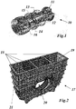
- the exemplary gas turbine 10 of fig. 1 is equipped with sequential combustion. It comprises a compressor 12 for compressing the combustion air, a first combustor 13, a first turbine 14, a second combustor 15 and a second turbine 16.
- the ambient air to be compressed by the compressor 12 enters the gas turbine through an air intake 11.
- Fig. 1 shows the bare gas turbine 10.
- the ambient air which is compressed by the compressor 12, usually has to be filtered and in some cases mixed with water by means of a fogging device, before being introduced into the compressor through the air duct, air intake manifold 17, and the air intake 11.
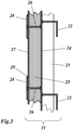
- an air intake manifold 17, as shown in fig. 2 is used to guide the air from the entrance of a gas turbine plant to the air intake 11 of gas turbine 10.
- the prior art air intake manifold 17 of fig. 2 is made up of several walls 18, which enclose an inner space with an inlet opening 19 and an outlet opening 20, the outlet opening 20 being adapted to the air intake 11 of the gas turbine 10.
- the air intake manifold 17 has a wall structure 21, which serves several purposes:
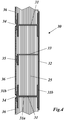
- the prior art air intake manifold 17 of fig. 2 has a wall structure 21 a part of which is shown in fig. 3 .
- a noise damping insulation is provided on and assembled from the inner side of the outer sheet 24.
- Insulation ribs 26, made of stainless steel (X6CrNiTi18-10 or similar) are welded on the outer sheet 24 forming square frames (see also fig. 2 ).
- Each frame is filled with a noise damping insulation material 25 made for example of melamine foam with a thickness of 45 mm.
- the noise damping insulation material 25 or melamine foam is covered with 3 mm thick perforated sheets 27 made of stainless steel.
- Fixation plates 28 are welded on the insulation ribs to keep the perforated sheets 27 in place.
- the wall structure of the invention comprises first means for mechanically supporting an outer sheet, which separates the spaces on both sides of the wall, e.g. the surroundings and the air duct of an air intake manifold, in an airtight manner, and further comprises second means for establishing noise damping insulation between the spaces on both sides of the wall, whereby said second means is secured to said first means, and said second means is integrated in said first means.
- the first means comprises a plurality of I-beams, which are arranged in a common plane with their webs oriented perpendicular to said common plane, the outer sheet is secured to a first one of the flanges of the I-beams, and said second means comprises the space between the I-beams being filled with a noise damping insulation material.
- the noise damping insulation material is enclosed between said outer sheet and perforated sheets, which are secured to a second one of the flanges of the I-beams.
- the I-beams and the outer sheet are made of a carbon steel, and the perforated sheets are made of stainless steel.
- a further embodiment is characterised in that the supporting structure with the I-beams is reinforced by providing intermediate beams between the I-beams, which intermediate beams support said perforated sheets.
- the intermediate beams are L-beams, and strips of stainless steel are provided between the perforated sheets and the L-beams.
- the perforated sheets are welded on the I-beams or intermediate strips, respectively, and the perforated sheets are provided with cut-outs being used for said welding.
- the perforated sheets are free of holes in a border area around said cut-outs. They can also be free of holes on their outer borders.
- the noise damping insulation material is a foam, especially on the basis of a melamine resin.
- a further embodiment of the invention is characterised in that the I-beams are of a standard IPB 100 type.
- Another embodiment of the invention is characterised in that the outer sheet has a thickness of 4 mm, the I-beams are corrosion protected, and the perforated sheets have a thickness of the 3 mm.
- the invention further provides a gas turbine comprising a compressor, which is supplied with air by means of an air intake manifold, characterised in that the walls of the air intake manifold have a wall structure according to the invention.
- the invention proposes to measures, namely the integration of the noise damping insulation in the wall structure (without insulation ribs), and the waiving of several small parts welded in the flow channel.
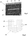
- the new wall structure 30 is composed of I-beams 31 (e.g. of the IPB 100 type), which are used as main structural elements.
- the I-beams 31, which are arranged in a common plane with their webs 31a oriented perpendicular to said common plane, support (with their inner flanges 31b) perforated sheets 36 on the inside of the structure.
- the frame 37 with its I-beams 31 is reinforced with additional L-beams 33.
- the L beams 33 also serve to support said perforated sheets 36, can support the insulation against movement and, if required can support the outer sheet 32.
- the outer sides or outer flanges 31b of the I-beams 31 are covered with a 4 mm thick outer sheet 32 of carbon steel to ensure air tightness.
- Stainless steel intermediate strips 34 and 35 are welded on the inner sides or flanges 31b of the I-beams 31 (i.e. in the flow channel) and L-beams 33.
- the space between the I-beams 31 and L-beams 33 is filled with 105 mm thick melamine foam as noise damping insulation material 25.
- the melamine foam is then covered with 3 mm thick stainless steel perforated sheets 36 (see fig. 6 ).
- the perforated sheets 36 are welded on the stainless steel intermediate strips 34 and 35.
- the provision of the stainless steel intermediate strips 34, 35 allows the application of cheap mild steel for the I-beams 31 (and L-beams 33).
- the stainless steel perforated sheets 36 are then welded to the stainless steel intermediate strips 34 and 35.
- cut-outs are only indicated for welding the I-beams 35. Similar cut outs can also be provided for welding the L-beams 33.
- the I-beams 31 of the invention have the advantage that they are stiff during welding. This is not the case for the insulation ribs 26 of the prior art, when the perforated sheets 27 and fixation plates 28 are welded to them.
- the perforated sheets 36 are preferably made from a large sheet, as shown in fig. 6 .
- cut-outs 38 are provided.
- the perforated sheets 36 are preferably free of holes 40 in a border area 39 around said cut-outs 38 so that the cut-outs 38 have straight borders being advantageous for the welding process.
- the perforated sheets 36 are preferably also free of holes 40 in for the outer border area of the perforated sheets 36.
- the melamine foam 25 is flexible and can be introduced between the I-beams 31 and L-Beams 33 without problems.
Description
- The present invention relates to the technology of gas turbines. It refers to a wall structure with noise damping insulation properties, especially for an air intake manifold of a gas turbine, according to the preamble of claim 1.
- Gas turbines use ambient air as combustion air for the combustion of fuel to generate hot gas, which drives a turbine. A typical industrial gas turbine, which is used as a stationary turbine for the generation of electric power, is shown in
fig. 1 . Theexemplary gas turbine 10 offig. 1 is equipped with sequential combustion. It comprises acompressor 12 for compressing the combustion air, afirst combustor 13, afirst turbine 14, asecond combustor 15 and asecond turbine 16. The ambient air to be compressed by thecompressor 12 enters the gas turbine through anair intake 11. -
Fig. 1 shows thebare gas turbine 10. The ambient air, which is compressed by thecompressor 12, usually has to be filtered and in some cases mixed with water by means of a fogging device, before being introduced into the compressor through the air duct,air intake manifold 17, and theair intake 11. In most cases, anair intake manifold 17, as shown infig. 2 , is used to guide the air from the entrance of a gas turbine plant to theair intake 11 ofgas turbine 10. - The prior art
air intake manifold 17 offig. 2 is made up ofseveral walls 18, which enclose an inner space with an inlet opening 19 and an outlet opening 20, the outlet opening 20 being adapted to theair intake 11 of thegas turbine 10. Theair intake manifold 17 has awall structure 21, which serves several purposes: - a) it must provide a sufficient mechanical stiffness, which is necessary for a box with outer dimensions of several metres;
- b) it must be airtight so that no unfiltered secondary air enters from outside; and
- c) it should have noise damping insulation properties so that the environment is protected against noise generated by the compressor and the air flowing through the air intake manifold.
- The prior art
air intake manifold 17 offig. 2 has a wall structure 21 a part of which is shown infig. 3 . A frame ofL beams 22, which is reinforced withcrossing ribs 23, supports from the outside anouter sheet 24, which separates the inner space (on the left ofouter sheet 24 infig. 3 ) of theair intake manifold 17 from the outside (on the right ofouter sheet 24fig. 3 ). - A noise damping insulation is provided on and assembled from the inner side of the
outer sheet 24.Insulation ribs 26, made of stainless steel (X6CrNiTi18-10 or similar) are welded on theouter sheet 24 forming square frames (see alsofig. 2 ). Each frame is filled with a noise dampinginsulation material 25 made for example of melamine foam with a thickness of 45 mm. The noise dampinginsulation material 25 or melamine foam is covered with 3 mm thickperforated sheets 27 made of stainless steel.Fixation plates 28 are welded on the insulation ribs to keep theperforated sheets 27 in place. An example of the prior art air intake manifold and wall structure is disclosed in documentUS 2008/0202848 A1 . - This prior art wall structure design has some disadvantages:
- there are two support structures: (1) a main structure made of L beams of the dimension 150x150x15 mm reinforced with ribs 100x10 mm from outside, and (2) an insulation structure made of stainless steel ribs 45x4 mm for carrying melamine foam and perforated sheets;
- a lot of small parts (e.g. fixation plates 28) are welded in the flow channel (inner space of air intake manifold);
- there can be deformations of the insulation ribs and walls during the welding process.
- Other kind of noise damping insulation are disclosed in documents
FR2940360 FR2934641 US5594216 andUS2008202848 . - It is therefore an object of the present invention to provide a wall structure, especially for an air intake manifold of a gas turbine, which avoids the disadvantages of the prior art wall structures, is easily assembled from a substantially reduced number of parts, and has a simplified structure without sacrificing mechanical integrity and stiffness.
- This and other objects are obtained by the wall structure according to claim 1.
- The wall structure of the invention comprises first means for mechanically supporting an outer sheet, which separates the spaces on both sides of the wall, e.g. the surroundings and the air duct of an air intake manifold, in an airtight manner, and further comprises second means for establishing noise damping insulation between the spaces on both sides of the wall, whereby said second means is secured to said first means, and said second means is integrated in said first means.
- According to the invention the first means comprises a plurality of I-beams, which are arranged in a common plane with their webs oriented perpendicular to said common plane, the outer sheet is secured to a first one of the flanges of the I-beams, and said second means comprises the space between the I-beams being filled with a noise damping insulation material.
- According to the invention the noise damping insulation material is enclosed between said outer sheet and perforated sheets, which are secured to a second one of the flanges of the I-beams.
- According to the invention the I-beams and the outer sheet are made of a carbon steel, and the perforated sheets are made of stainless steel.
- Intermediate strips of stainless steel are provided between the perforated sheets and the second one of the flanges of the I-beams.
- A further embodiment is characterised in that the supporting structure with the I-beams is reinforced by providing intermediate beams between the I-beams, which intermediate beams support said perforated sheets.
- Preferably, the intermediate beams are L-beams, and strips of stainless steel are provided between the perforated sheets and the L-beams.
- According to another embodiment of the invention the perforated sheets are welded on the I-beams or intermediate strips, respectively, and the perforated sheets are provided with cut-outs being used for said welding.
- Especially, the perforated sheets are free of holes in a border area around said cut-outs. They can also be free of holes on their outer borders.
- According to another embodiment of the invention the noise damping insulation material is a foam, especially on the basis of a melamine resin.
- A further embodiment of the invention is characterised in that the I-beams are of a standard IPB 100 type.
- Another embodiment of the invention is characterised in that the outer sheet has a thickness of 4 mm, the I-beams are corrosion protected, and the perforated sheets have a thickness of the 3 mm.
- The invention further provides a gas turbine comprising a compressor, which is supplied with air by means of an air intake manifold, characterised in that the walls of the air intake manifold have a wall structure according to the invention.
- The present invention is now to be explained more closely by means of different embodiments and with reference to the attached drawings.
- Fig. 1
- shows a perspective view of a stationary gas turbine of the type GT26 with sequential combustion;
- Fig. 2
- shows a perspective view of a prior art air intake manifold for the turbine of
fig. 1 ; - Fig. 3
- shows a cross-section of the wall structure of the air intake manifold of
fig. 2 ; - Fig. 4
- shows a cross-section of the wall structure of an air intake manifold according to an embodiment of the invention;
- Fig. 5
- shows a front view from the interior on the wall of a partially assembled air intake manifold (without melamine foam and perforated plates) according to an embodiment of the invention; and
- Fig. 6
- shows a section of the perforated sheet used in a wall structure according to
fig. 4 . - The invention proposes to measures, namely the integration of the noise damping insulation in the wall structure (without insulation ribs), and the waiving of several small parts welded in the flow channel.
- According to
fig. 4 and5 thenew wall structure 30 is composed of I-beams 31 (e.g. of the IPB 100 type), which are used as main structural elements. The I-beams 31, which are arranged in a common plane with theirwebs 31a oriented perpendicular to said common plane, support (with theirinner flanges 31b) perforatedsheets 36 on the inside of the structure. To increase stiffness and fulfil structural resonance criteria, theframe 37 with its I-beams 31 is reinforced with additional L-beams 33. The L beams 33 also serve to support saidperforated sheets 36, can support the insulation against movement and, if required can support theouter sheet 32. - The outer sides or
outer flanges 31b of the I-beams 31 are covered with a 4 mm thickouter sheet 32 of carbon steel to ensure air tightness. Stainless steel intermediate strips 34 and 35 are welded on the inner sides orflanges 31b of the I-beams 31 (i.e. in the flow channel) and L-beams 33. After a corrosion protection is applied to the structures (37) without perforated plates (36) and without melamine foam (25),, the space between the I-beams 31 and L-beams 33 is filled with 105 mm thick melamine foam as noise dampinginsulation material 25. The melamine foam is then covered with 3 mm thick stainless steel perforated sheets 36 (seefig. 6 ). Theperforated sheets 36 are welded on the stainless steel intermediate strips 34 and 35. - The provision of the stainless steel intermediate strips 34, 35 allows the application of cheap mild steel for the I-beams 31 (and L-beams 33). The stainless steel perforated
sheets 36 are then welded to the stainless steel intermediate strips 34 and 35. In the example ofFig. 4 cut-outs are only indicated for welding the I-beams 35. Similar cut outs can also be provided for welding the L-beams 33. - The I-
beams 31 of the invention have the advantage that they are stiff during welding. This is not the case for theinsulation ribs 26 of the prior art, when theperforated sheets 27 andfixation plates 28 are welded to them. - The
perforated sheets 36 are preferably made from a large sheet, as shown infig. 6 . For welding purposes cut-outs 38 are provided. Theperforated sheets 36 are preferably free ofholes 40 in aborder area 39 around said cut-outs 38 so that the cut-outs 38 have straight borders being advantageous for the welding process. Theperforated sheets 36 are preferably also free ofholes 40 in for the outer border area of theperforated sheets 36. - The
melamine foam 25 is flexible and can be introduced between the I-beams 31 and L-Beams 33 without problems. -
- 10
- gas turbine
- 11
- air intake
- 12
- compressor
- 13, 15
- combustor
- 14, 16
- turbine
- 17
- air intake manifold
- 18
- wall
- 19
- inlet opening
- 20
- outlet opening
- 21, 30
- wall structure
- 22, 33
- L-beam
- 23
- rib
- 24, 32
- outer sheet
- 25
- noise damping insulation material (e.g. melamine foam)
- 26
- insulation rib (stainless steel)
- 27, 36
- perforated sheet (stainless steel)
- 28
- fixation plate
- 29
- welding
- 31
- I-beam
- 31a
- web
- 31b
- flange
- 34, 35
- intermediate strip (stainless steel)
- 37
- frame
- 38
- cut-out
- 39
- border area
- 40
- hole
Claims (9)
- Wall structure (30) with noise damping insulation properties, for an air intake manifold of a gas turbine (10), comprising first means (31, 33) for mechanically supporting an outer sheet (32), which separates the spaces on both sides of the wall in an airtight manner, and further comprising second means (25, 34-36) for establishing noise damping insulation between the spaces on both sides of the wall, whereby said second means (25, 34-36) is secured to said first means (31, 33), and said second means (25, 34-36) is integrated in said first means (31, 33); the first means comprising a plurality of I-beams (31), which are arranged in a common plane with their webs (31a) oriented perpendicular to said common plane, the outer sheet (32) is secured to a first one of the flanges (31b) of the I-beams (31), and said second means comprising the space between the I-beams (31) being filled with a noise damping insulation material (25); wherein the noise damping insulation material (25) is enclosed between said outer sheet (32) and perforated sheets (36), which are secured to a second one of the flanges (31b) of the I-beams (31);
the wall structure being characterised in that the I-beams (31) and the outer sheet (32) are made of a carbon steel and the perforated sheets (36) are made of stainless steel, and in that intermediate strips (34) of stainless steel are provided between the perforated sheets (36) and the second one of the flanges (31b) of the I-beams (31). - Wall structure according to claim 1, comprising intermediate L-beams (33) arranged between the I-beams (31); wherein intermediate L-beams (33) support said perforated sheets (36) and/ or the outer sheet (32).
- Wall structure according to claim 2, characterised in that the intermediate beams are L-beams (33), and strips (35) of stainless steel are provided between the perforated sheets (36) and the L-beams (33).
- Wall structure according to one of the foregoing claims, characterised in that the perforated sheets (36) are welded on the I-beams (31) or intermediate strips (34, 35), respectively, and the perforated sheets (36) are provided with cut-outs (38) being used for said welding.
- Wall structure according to claim 4, characterised in that the perforated sheets (36) are free of holes (40) in a border area (39) around said cut-outs (38).
- Wall structure according to anyone of the foregoing claims, characterised in that the noise damping insulation material (25) is a foam, especially on the basis of a melamine resin.
- Wall structure according to anyone of the foregoing claims, characterised in that the I-beams are of a standard IPB 100 type.
- Wall structure according to anyone of the foregoing claims, characterised in that the outer sheet (32) has a thickness of 4 mm, the I-beams (31) are corrosion protected, and the perforated sheets (36) have a thickness of 3 mm.
- Gas turbine (10) comprising a compressor (12), which is supplied with air by means of an air intake manifold, characterised in that the walls of the air intake manifold have a wall structure according to one of the claims 1 to 8.
Priority Applications (1)
| Application Number | Priority Date | Filing Date | Title |
|---|---|---|---|
| EP12182765.3A EP2568144B1 (en) | 2011-09-12 | 2012-09-03 | Wall structure with noise damping insulation properties and gas turbine with such a wall structure |
Applications Claiming Priority (2)
| Application Number | Priority Date | Filing Date | Title |
|---|---|---|---|
| EP11180934 | 2011-09-12 | ||
| EP12182765.3A EP2568144B1 (en) | 2011-09-12 | 2012-09-03 | Wall structure with noise damping insulation properties and gas turbine with such a wall structure |
Publications (3)
| Publication Number | Publication Date |
|---|---|
| EP2568144A2 EP2568144A2 (en) | 2013-03-13 |
| EP2568144A3 EP2568144A3 (en) | 2017-03-01 |
| EP2568144B1 true EP2568144B1 (en) | 2019-11-06 |
Family
ID=46727155
Family Applications (1)
| Application Number | Title | Priority Date | Filing Date |
|---|---|---|---|
| EP12182765.3A Active EP2568144B1 (en) | 2011-09-12 | 2012-09-03 | Wall structure with noise damping insulation properties and gas turbine with such a wall structure |
Country Status (3)
| Country | Link |
|---|---|
| US (1) | US9260859B2 (en) |
| EP (1) | EP2568144B1 (en) |
| RU (1) | RU2545266C2 (en) |
Families Citing this family (5)
| Publication number | Priority date | Publication date | Assignee | Title |
|---|---|---|---|---|
| US9771868B2 (en) * | 2015-07-21 | 2017-09-26 | The Boeing Company | Sound attenuation apparatus and method |
| US9587563B2 (en) | 2015-07-21 | 2017-03-07 | The Boeing Company | Sound attenuation apparatus and method |
| GB201517171D0 (en) * | 2015-09-29 | 2015-11-11 | Rolls Royce Plc | A casing for a gas turbine engine and a method of manufacturing such a casing |
| US9714630B2 (en) * | 2015-10-07 | 2017-07-25 | General Electric Company | Noise baffle for a rotary machine and method of making same |
| CN108843452B (en) * | 2018-06-14 | 2021-10-26 | 哈尔滨工业大学(威海) | Gas turbine case packing body for boats and ships |
Family Cites Families (17)
| Publication number | Priority date | Publication date | Assignee | Title |
|---|---|---|---|---|
| US4452335A (en) * | 1982-05-03 | 1984-06-05 | United Technologies Corporation | Sound absorbing structure for a gas turbine engine |
| IT1185449B (en) * | 1985-10-16 | 1987-11-12 | Nuovo Pignone Spa | EXHAUST SILENCER PERFECTED FOR HIGH-POWER GAS TURBINES |
| US4944362A (en) * | 1988-11-25 | 1990-07-31 | General Electric Company | Closed cavity noise suppressor |
| US5594216A (en) * | 1994-11-29 | 1997-01-14 | Lockheed Missiles & Space Co., Inc. | Jet engine sound-insulation structure |
| TW360744B (en) * | 1996-07-15 | 1999-06-11 | Siemens Ag | Equipment for fixing a covering sheet metal in the waste-gas flue of a gas turbine as well as halting |
| US6182787B1 (en) * | 1999-01-12 | 2001-02-06 | General Electric Company | Rigid sandwich panel acoustic treatment |
| US6439340B1 (en) * | 2000-11-17 | 2002-08-27 | Astech Manufacturing, Inc. | Acoustically treated structurally reinforced sound absorbing panel |
| US6802690B2 (en) * | 2001-05-30 | 2004-10-12 | M & I Heat Transfer Products, Ltd. | Outlet silencer structures for turbine |
| FR2844303B1 (en) * | 2002-09-10 | 2006-05-05 | Airbus France | TUBULAR ACOUSTICAL ATTENUATION PIECE FOR AIRCRAFT REACTOR AIR INTAKE |
| RU2241843C1 (en) | 2003-07-14 | 2004-12-10 | Открытое акционерное общество Научно-производственное объединение "Искра" | Noise-absorbing hood of gas-turbine plant |
| US7467687B2 (en) * | 2004-11-12 | 2008-12-23 | General Electric Company | Thermal—acoustic enclosure |
| DE502006001958D1 (en) | 2005-08-08 | 2008-12-11 | Alstom Technology Ltd | MUFFLER FOR GAS TURBINE SYSTEMS |
| EP2192289B1 (en) * | 2007-09-13 | 2012-04-25 | Alphatech CO., LTD. | Intake silencer for gas turbine |
| CA2731974A1 (en) * | 2008-07-30 | 2010-02-04 | Aircelle | Acoustic attenuation panel for aircraft engine nacelle |
| FR2934641B1 (en) * | 2008-07-30 | 2011-03-04 | Aircelle Sa | ACOUSTICAL ATTENUATION PANEL FOR AN AIRCRAFT ENGINE NACELLE |
| FR2940360B1 (en) * | 2008-12-22 | 2011-10-07 | Aircelle Sa | ACOUSTICAL ATTENUATION PANEL FOR AN AIRCRAFT ENGINE NACELLE, AIR INTAKE STRUCTURE AND FIXED INTERNAL STRUCTURE INCORPORATING SAID PANEL |
| US7798285B2 (en) * | 2008-11-14 | 2010-09-21 | Rohr, Inc. | Acoustic barrel for aircraft engine nacelle including crack and delamination stoppers |
-
2012
- 2012-09-03 EP EP12182765.3A patent/EP2568144B1/en active Active
- 2012-09-05 US US13/604,373 patent/US9260859B2/en not_active Expired - Fee Related
- 2012-09-11 RU RU2012138961/06A patent/RU2545266C2/en active
Non-Patent Citations (1)
| Title |
|---|
| None * |
Also Published As
| Publication number | Publication date |
|---|---|
| EP2568144A3 (en) | 2017-03-01 |
| EP2568144A2 (en) | 2013-03-13 |
| US20130071231A1 (en) | 2013-03-21 |
| RU2545266C2 (en) | 2015-03-27 |
| RU2012138961A (en) | 2014-04-27 |
| US9260859B2 (en) | 2016-02-16 |
Similar Documents
| Publication | Publication Date | Title |
|---|---|---|
| EP2568144B1 (en) | Wall structure with noise damping insulation properties and gas turbine with such a wall structure | |
| US9546582B1 (en) | Silencer panel having sections and related silencer duct | |
| KR101750957B1 (en) | Acoustic panel and soundproof wall equipment | |
| US8689932B2 (en) | On-base enclosure | |
| JP2007321761A (en) | Thermoacoustic enclosure and gas turbine engine assembly | |
| AU2019201909B2 (en) | Enclosure for a gas turbine engine | |
| EP2256305B1 (en) | Corrugated hood for low pressure steam turbine | |
| US8556028B1 (en) | Acoustic module for enclosure panel | |
| JP2015086875A (en) | Gas turbine enclosure | |
| JP5614624B2 (en) | Blast pressure reduction structure | |
| US11174033B2 (en) | Metal insulating part | |
| US11591954B2 (en) | Enclosure segments for forming an enclosure for an engine generator set | |
| US10465714B2 (en) | Silencer duct having silencing element and couplers | |
| EP3144503B1 (en) | Silencer panel and system having plastic perforated side wall | |
| JP2010001632A (en) | Earthquake-resisting wall forming method | |
| JP2009076523A (en) | Sound insulating panel and sound insulating wall | |
| JP5601501B2 (en) | Blast pressure reduction structure | |
| US9389001B2 (en) | Boiler, and a silencer for a flue gas duct in a boiler | |
| JP6375339B2 (en) | Sound absorbing panel and soundproofing equipment | |
| JP4772393B2 (en) | Ship interior divider | |
| JP6649119B2 (en) | Exhaust gas silencer, gas turbine equipment, and nuclear power plant | |
| JP3112472U (en) | Shielding sheet for air conditioning equipment | |
| JP2020193748A (en) | Housing | |
| JP2008223410A (en) | Sound absorbing panel | |
| SE518302C2 (en) | Match arrangement for opening in wall comprises hatch positionable in closed position in frame fitted on wall so that opening is covered by it |
Legal Events
| Date | Code | Title | Description |
|---|---|---|---|
| PUAI | Public reference made under article 153(3) epc to a published international application that has entered the european phase |
Free format text: ORIGINAL CODE: 0009012 |
|
| AK | Designated contracting states |
Kind code of ref document: A2 Designated state(s): AL AT BE BG CH CY CZ DE DK EE ES FI FR GB GR HR HU IE IS IT LI LT LU LV MC MK MT NL NO PL PT RO RS SE SI SK SM TR |
|
| AX | Request for extension of the european patent |
Extension state: BA ME |
|
| RAP1 | Party data changed (applicant data changed or rights of an application transferred) |
Owner name: GENERAL ELECTRIC TECHNOLOGY GMBH |
|
| PUAL | Search report despatched |
Free format text: ORIGINAL CODE: 0009013 |
|
| AK | Designated contracting states |
Kind code of ref document: A3 Designated state(s): AL AT BE BG CH CY CZ DE DK EE ES FI FR GB GR HR HU IE IS IT LI LT LU LV MC MK MT NL NO PL PT RO RS SE SI SK SM TR |
|
| AX | Request for extension of the european patent |
Extension state: BA ME |
|
| RIC1 | Information provided on ipc code assigned before grant |
Ipc: F02C 7/045 20060101AFI20170120BHEP Ipc: F02C 7/24 20060101ALI20170120BHEP Ipc: F04D 29/66 20060101ALI20170120BHEP |
|
| RAP1 | Party data changed (applicant data changed or rights of an application transferred) |
Owner name: ANSALDO ENERGIA IP UK LIMITED |
|
| STAA | Information on the status of an ep patent application or granted ep patent |
Free format text: STATUS: REQUEST FOR EXAMINATION WAS MADE |
|
| 17P | Request for examination filed |
Effective date: 20170825 |
|
| RBV | Designated contracting states (corrected) |
Designated state(s): AL AT BE BG CH CY CZ DE DK EE ES FI FR GB GR HR HU IE IS IT LI LT LU LV MC MK MT NL NO PL PT RO RS SE SI SK SM TR |
|
| REG | Reference to a national code |
Ref country code: DE Ref legal event code: R079 Ref document number: 602012065389 Country of ref document: DE Free format text: PREVIOUS MAIN CLASS: F02C0007045000 Ipc: E04B0001840000 |
|
| GRAP | Despatch of communication of intention to grant a patent |
Free format text: ORIGINAL CODE: EPIDOSNIGR1 |
|
| STAA | Information on the status of an ep patent application or granted ep patent |
Free format text: STATUS: GRANT OF PATENT IS INTENDED |
|
| RIC1 | Information provided on ipc code assigned before grant |
Ipc: E04B 2/00 20060101ALI20181129BHEP Ipc: F04D 29/52 20060101ALI20181129BHEP Ipc: F04D 29/66 20060101ALI20181129BHEP Ipc: F02C 7/045 20060101ALI20181129BHEP Ipc: E04B 1/84 20060101AFI20181129BHEP Ipc: F04D 29/02 20060101ALI20181129BHEP |
|
| INTG | Intention to grant announced |
Effective date: 20190102 |
|
| GRAS | Grant fee paid |
Free format text: ORIGINAL CODE: EPIDOSNIGR3 |
|
| GRAA | (expected) grant |
Free format text: ORIGINAL CODE: 0009210 |
|
| STAA | Information on the status of an ep patent application or granted ep patent |
Free format text: STATUS: THE PATENT HAS BEEN GRANTED |
|
| AK | Designated contracting states |
Kind code of ref document: B1 Designated state(s): AL AT BE BG CH CY CZ DE DK EE ES FI FR GB GR HR HU IE IS IT LI LT LU LV MC MK MT NL NO PL PT RO RS SE SI SK SM TR |
|
| REG | Reference to a national code |
Ref country code: GB Ref legal event code: FG4D |
|
| REG | Reference to a national code |
Ref country code: CH Ref legal event code: EP Ref country code: AT Ref legal event code: REF Ref document number: 1198913 Country of ref document: AT Kind code of ref document: T Effective date: 20191115 |
|
| REG | Reference to a national code |
Ref country code: IE Ref legal event code: FG4D |
|
| REG | Reference to a national code |
Ref country code: DE Ref legal event code: R096 Ref document number: 602012065389 Country of ref document: DE |
|
| REG | Reference to a national code |
Ref country code: NL Ref legal event code: MP Effective date: 20191106 |
|
| REG | Reference to a national code |
Ref country code: LT Ref legal event code: MG4D |
|
| PG25 | Lapsed in a contracting state [announced via postgrant information from national office to epo] |
Ref country code: NO Free format text: LAPSE BECAUSE OF FAILURE TO SUBMIT A TRANSLATION OF THE DESCRIPTION OR TO PAY THE FEE WITHIN THE PRESCRIBED TIME-LIMIT Effective date: 20200206 Ref country code: PT Free format text: LAPSE BECAUSE OF FAILURE TO SUBMIT A TRANSLATION OF THE DESCRIPTION OR TO PAY THE FEE WITHIN THE PRESCRIBED TIME-LIMIT Effective date: 20200306 Ref country code: FI Free format text: LAPSE BECAUSE OF FAILURE TO SUBMIT A TRANSLATION OF THE DESCRIPTION OR TO PAY THE FEE WITHIN THE PRESCRIBED TIME-LIMIT Effective date: 20191106 Ref country code: BG Free format text: LAPSE BECAUSE OF FAILURE TO SUBMIT A TRANSLATION OF THE DESCRIPTION OR TO PAY THE FEE WITHIN THE PRESCRIBED TIME-LIMIT Effective date: 20200206 Ref country code: LV Free format text: LAPSE BECAUSE OF FAILURE TO SUBMIT A TRANSLATION OF THE DESCRIPTION OR TO PAY THE FEE WITHIN THE PRESCRIBED TIME-LIMIT Effective date: 20191106 Ref country code: SE Free format text: LAPSE BECAUSE OF FAILURE TO SUBMIT A TRANSLATION OF THE DESCRIPTION OR TO PAY THE FEE WITHIN THE PRESCRIBED TIME-LIMIT Effective date: 20191106 Ref country code: PL Free format text: LAPSE BECAUSE OF FAILURE TO SUBMIT A TRANSLATION OF THE DESCRIPTION OR TO PAY THE FEE WITHIN THE PRESCRIBED TIME-LIMIT Effective date: 20191106 Ref country code: GR Free format text: LAPSE BECAUSE OF FAILURE TO SUBMIT A TRANSLATION OF THE DESCRIPTION OR TO PAY THE FEE WITHIN THE PRESCRIBED TIME-LIMIT Effective date: 20200207 Ref country code: LT Free format text: LAPSE BECAUSE OF FAILURE TO SUBMIT A TRANSLATION OF THE DESCRIPTION OR TO PAY THE FEE WITHIN THE PRESCRIBED TIME-LIMIT Effective date: 20191106 Ref country code: ES Free format text: LAPSE BECAUSE OF FAILURE TO SUBMIT A TRANSLATION OF THE DESCRIPTION OR TO PAY THE FEE WITHIN THE PRESCRIBED TIME-LIMIT Effective date: 20191106 Ref country code: NL Free format text: LAPSE BECAUSE OF FAILURE TO SUBMIT A TRANSLATION OF THE DESCRIPTION OR TO PAY THE FEE WITHIN THE PRESCRIBED TIME-LIMIT Effective date: 20191106 |
|
| PG25 | Lapsed in a contracting state [announced via postgrant information from national office to epo] |
Ref country code: IS Free format text: LAPSE BECAUSE OF FAILURE TO SUBMIT A TRANSLATION OF THE DESCRIPTION OR TO PAY THE FEE WITHIN THE PRESCRIBED TIME-LIMIT Effective date: 20200306 Ref country code: HR Free format text: LAPSE BECAUSE OF FAILURE TO SUBMIT A TRANSLATION OF THE DESCRIPTION OR TO PAY THE FEE WITHIN THE PRESCRIBED TIME-LIMIT Effective date: 20191106 Ref country code: RS Free format text: LAPSE BECAUSE OF FAILURE TO SUBMIT A TRANSLATION OF THE DESCRIPTION OR TO PAY THE FEE WITHIN THE PRESCRIBED TIME-LIMIT Effective date: 20191106 |
|
| PG25 | Lapsed in a contracting state [announced via postgrant information from national office to epo] |
Ref country code: AL Free format text: LAPSE BECAUSE OF FAILURE TO SUBMIT A TRANSLATION OF THE DESCRIPTION OR TO PAY THE FEE WITHIN THE PRESCRIBED TIME-LIMIT Effective date: 20191106 |
|
| PG25 | Lapsed in a contracting state [announced via postgrant information from national office to epo] |
Ref country code: DK Free format text: LAPSE BECAUSE OF FAILURE TO SUBMIT A TRANSLATION OF THE DESCRIPTION OR TO PAY THE FEE WITHIN THE PRESCRIBED TIME-LIMIT Effective date: 20191106 Ref country code: EE Free format text: LAPSE BECAUSE OF FAILURE TO SUBMIT A TRANSLATION OF THE DESCRIPTION OR TO PAY THE FEE WITHIN THE PRESCRIBED TIME-LIMIT Effective date: 20191106 Ref country code: RO Free format text: LAPSE BECAUSE OF FAILURE TO SUBMIT A TRANSLATION OF THE DESCRIPTION OR TO PAY THE FEE WITHIN THE PRESCRIBED TIME-LIMIT Effective date: 20191106 Ref country code: CZ Free format text: LAPSE BECAUSE OF FAILURE TO SUBMIT A TRANSLATION OF THE DESCRIPTION OR TO PAY THE FEE WITHIN THE PRESCRIBED TIME-LIMIT Effective date: 20191106 |
|
| REG | Reference to a national code |
Ref country code: DE Ref legal event code: R097 Ref document number: 602012065389 Country of ref document: DE |
|
| REG | Reference to a national code |
Ref country code: AT Ref legal event code: MK05 Ref document number: 1198913 Country of ref document: AT Kind code of ref document: T Effective date: 20191106 |
|
| PG25 | Lapsed in a contracting state [announced via postgrant information from national office to epo] |
Ref country code: SM Free format text: LAPSE BECAUSE OF FAILURE TO SUBMIT A TRANSLATION OF THE DESCRIPTION OR TO PAY THE FEE WITHIN THE PRESCRIBED TIME-LIMIT Effective date: 20191106 Ref country code: SK Free format text: LAPSE BECAUSE OF FAILURE TO SUBMIT A TRANSLATION OF THE DESCRIPTION OR TO PAY THE FEE WITHIN THE PRESCRIBED TIME-LIMIT Effective date: 20191106 |
|
| PLBE | No opposition filed within time limit |
Free format text: ORIGINAL CODE: 0009261 |
|
| STAA | Information on the status of an ep patent application or granted ep patent |
Free format text: STATUS: NO OPPOSITION FILED WITHIN TIME LIMIT |
|
| 26N | No opposition filed |
Effective date: 20200807 |
|
| PG25 | Lapsed in a contracting state [announced via postgrant information from national office to epo] |
Ref country code: AT Free format text: LAPSE BECAUSE OF FAILURE TO SUBMIT A TRANSLATION OF THE DESCRIPTION OR TO PAY THE FEE WITHIN THE PRESCRIBED TIME-LIMIT Effective date: 20191106 Ref country code: SI Free format text: LAPSE BECAUSE OF FAILURE TO SUBMIT A TRANSLATION OF THE DESCRIPTION OR TO PAY THE FEE WITHIN THE PRESCRIBED TIME-LIMIT Effective date: 20191106 |
|
| PG25 | Lapsed in a contracting state [announced via postgrant information from national office to epo] |
Ref country code: IT Free format text: LAPSE BECAUSE OF FAILURE TO SUBMIT A TRANSLATION OF THE DESCRIPTION OR TO PAY THE FEE WITHIN THE PRESCRIBED TIME-LIMIT Effective date: 20191106 |
|
| PG25 | Lapsed in a contracting state [announced via postgrant information from national office to epo] |
Ref country code: MC Free format text: LAPSE BECAUSE OF FAILURE TO SUBMIT A TRANSLATION OF THE DESCRIPTION OR TO PAY THE FEE WITHIN THE PRESCRIBED TIME-LIMIT Effective date: 20191106 |
|
| REG | Reference to a national code |
Ref country code: CH Ref legal event code: PL |
|
| GBPC | Gb: european patent ceased through non-payment of renewal fee |
Effective date: 20200903 |
|
| REG | Reference to a national code |
Ref country code: BE Ref legal event code: MM Effective date: 20200930 |
|
| PG25 | Lapsed in a contracting state [announced via postgrant information from national office to epo] |
Ref country code: LU Free format text: LAPSE BECAUSE OF NON-PAYMENT OF DUE FEES Effective date: 20200903 |
|
| PG25 | Lapsed in a contracting state [announced via postgrant information from national office to epo] |
Ref country code: FR Free format text: LAPSE BECAUSE OF NON-PAYMENT OF DUE FEES Effective date: 20200930 |
|
| PG25 | Lapsed in a contracting state [announced via postgrant information from national office to epo] |
Ref country code: GB Free format text: LAPSE BECAUSE OF NON-PAYMENT OF DUE FEES Effective date: 20200903 Ref country code: LI Free format text: LAPSE BECAUSE OF NON-PAYMENT OF DUE FEES Effective date: 20200930 Ref country code: IE Free format text: LAPSE BECAUSE OF NON-PAYMENT OF DUE FEES Effective date: 20200903 Ref country code: CH Free format text: LAPSE BECAUSE OF NON-PAYMENT OF DUE FEES Effective date: 20200930 Ref country code: BE Free format text: LAPSE BECAUSE OF NON-PAYMENT OF DUE FEES Effective date: 20200930 |
|
| PG25 | Lapsed in a contracting state [announced via postgrant information from national office to epo] |
Ref country code: TR Free format text: LAPSE BECAUSE OF FAILURE TO SUBMIT A TRANSLATION OF THE DESCRIPTION OR TO PAY THE FEE WITHIN THE PRESCRIBED TIME-LIMIT Effective date: 20191106 Ref country code: MT Free format text: LAPSE BECAUSE OF FAILURE TO SUBMIT A TRANSLATION OF THE DESCRIPTION OR TO PAY THE FEE WITHIN THE PRESCRIBED TIME-LIMIT Effective date: 20191106 Ref country code: CY Free format text: LAPSE BECAUSE OF FAILURE TO SUBMIT A TRANSLATION OF THE DESCRIPTION OR TO PAY THE FEE WITHIN THE PRESCRIBED TIME-LIMIT Effective date: 20191106 |
|
| PG25 | Lapsed in a contracting state [announced via postgrant information from national office to epo] |
Ref country code: MK Free format text: LAPSE BECAUSE OF FAILURE TO SUBMIT A TRANSLATION OF THE DESCRIPTION OR TO PAY THE FEE WITHIN THE PRESCRIBED TIME-LIMIT Effective date: 20191106 |
|
| PGFP | Annual fee paid to national office [announced via postgrant information from national office to epo] |
Ref country code: DE Payment date: 20220920 Year of fee payment: 11 |