EP2568080A1 - Scissoring door block device with adjustable door block width - Google Patents
Scissoring door block device with adjustable door block width Download PDFInfo
- Publication number
- EP2568080A1 EP2568080A1 EP11849106A EP11849106A EP2568080A1 EP 2568080 A1 EP2568080 A1 EP 2568080A1 EP 11849106 A EP11849106 A EP 11849106A EP 11849106 A EP11849106 A EP 11849106A EP 2568080 A1 EP2568080 A1 EP 2568080A1
- Authority
- EP
- European Patent Office
- Prior art keywords
- eccentric
- adjusting
- thread
- swing arm
- shaft
- Prior art date
- Legal status (The legal status is an assumption and is not a legal conclusion. Google has not performed a legal analysis and makes no representation as to the accuracy of the status listed.)
- Granted
Links
- 230000000903 blocking effect Effects 0.000 claims abstract description 29
- 230000005540 biological transmission Effects 0.000 description 10
- 230000000694 effects Effects 0.000 description 5
- 239000003638 chemical reducing agent Substances 0.000 description 2
- NJPPVKZQTLUDBO-UHFFFAOYSA-N novaluron Chemical compound C1=C(Cl)C(OC(F)(F)C(OC(F)(F)F)F)=CC=C1NC(=O)NC(=O)C1=C(F)C=CC=C1F NJPPVKZQTLUDBO-UHFFFAOYSA-N 0.000 description 2
- 230000002411 adverse Effects 0.000 description 1
- 230000003247 decreasing effect Effects 0.000 description 1
- 238000010586 diagram Methods 0.000 description 1
- 239000000463 material Substances 0.000 description 1
Images



Classifications
-
- E—FIXED CONSTRUCTIONS
- E05—LOCKS; KEYS; WINDOW OR DOOR FITTINGS; SAFES
- E05F—DEVICES FOR MOVING WINGS INTO OPEN OR CLOSED POSITION; CHECKS FOR WINGS; WING FITTINGS NOT OTHERWISE PROVIDED FOR, CONCERNED WITH THE FUNCTIONING OF THE WING
- E05F15/00—Power-operated mechanisms for wings
- E05F15/60—Power-operated mechanisms for wings using electrical actuators
- E05F15/603—Power-operated mechanisms for wings using electrical actuators using rotary electromotors
- E05F15/611—Power-operated mechanisms for wings using electrical actuators using rotary electromotors for swinging wings
-
- E—FIXED CONSTRUCTIONS
- E05—LOCKS; KEYS; WINDOW OR DOOR FITTINGS; SAFES
- E05F—DEVICES FOR MOVING WINGS INTO OPEN OR CLOSED POSITION; CHECKS FOR WINGS; WING FITTINGS NOT OTHERWISE PROVIDED FOR, CONCERNED WITH THE FUNCTIONING OF THE WING
- E05F15/00—Power-operated mechanisms for wings
-
- E—FIXED CONSTRUCTIONS
- E05—LOCKS; KEYS; WINDOW OR DOOR FITTINGS; SAFES
- E05Y—INDEXING SCHEME ASSOCIATED WITH SUBCLASSES E05D AND E05F, RELATING TO CONSTRUCTION ELEMENTS, ELECTRIC CONTROL, POWER SUPPLY, POWER SIGNAL OR TRANSMISSION, USER INTERFACES, MOUNTING OR COUPLING, DETAILS, ACCESSORIES, AUXILIARY OPERATIONS NOT OTHERWISE PROVIDED FOR, APPLICATION THEREOF
- E05Y2900/00—Application of doors, windows, wings or fittings thereof
- E05Y2900/40—Application of doors, windows, wings or fittings thereof for gates
Definitions
- the invention relates to a scissor-type blocking apparatus, in particular to a transmission connecting mechanism positioned between a drive apparatus and a gate-leaf swing arm.
- Rail transit stations such as transit stations of subways, light railways, railroads and so on, generally establish an automatic fare gate to control passengers and cargos.
- a scissor-type gate blocking apparatus belongs to one kind of the automatic fare gate.
- the width of a passage of the scissor-type blocking apparatus is determined by the width of a gate leaf functioning as blocking when the leaf is closed.
- the transmission connecting mechanism driving the gate leaf to be opened or closed and positioned between the drive apparatus and the swing arm of the gate leaf, determines the blocking amplitude of the gate leaf.
- the disclosed transmission connecting mechanism between the drive apparatus and the swing arm of the gate leaf has the following several categories: According to publication patent number CN201053282 of "Scissor-Type Gate Structure for Fare Gate", a gate is opened and closed with the adoption of a connecting crank - swing rod transmission mechanism between a motor and a gate leaf; according to publication patent number CN2635850 of "Control Apparatus of Access Gate of Gate Leaf”, a motor is adopted to drive an eccentric transmission disk driving a traction plate connecting a swing arm of a gate leaf, thereby opening or closing the gate leaf; according to publication patent number CN201037352 of "Scissor-Type Gate for Automatic Fare Gate”, a motor drives an eccentric disk driving a connecting rod to draw a swing arm, so as to open or close a gate leaf.
- the transmission connecting apparatus in the abovementioned prior art mainly consists of an eccentric disk or a crank and a connecting rod playing the same role or a traction plate and a swing rod playing the same role.
- either the eccentric amount of the eccentric disk or the length of the connecting rod is a constant value and cannot be adjusted, thereby determining that the blocking amplitude of the gate leaf is not a constant value. If the width of a passage needs to be adjusted, the transmission connecting mechanism consisting of an eccentric disk with other eccentric amount and the connecting rod with other length must be replaced, thus costing manpower and material resources and being adverse to fully utilize equipment.
- the invention provides the following technical solutions: a transmission connecting mechanism adjusting the length of a connecting rod and the eccentric amount of an eccentric disk is provided, so as to achieve a scissor-type blocking apparatus adjusting the blocking width of a gate leaf within a certain range.
- the apparatus comprises a shaft 1 and an active swing arm 4, wherein it also comprises an eccentric disk 21 connected with the shaft 1 and eccentrically provided with a plurality of mounted holes 211 of the eccentric disk 21, an eccentric amount adjusting piece 22 connected with the eccentric disk 21 through the mounted hole 211 of the eccentric disk 21, a small shaft 223 eccentrically fixed at the eccentric amount adjusting piece 22, and a connecting rod mechanism 3 adjusting its length retractably and is connected with the active swing arm 4.
- the invention has the following technical effects: the eccentric disk in the prior art is directly with the small shaft 223 together, and the small shaft 223 is freely connected with the connecting rod again. Under such conditions, the eccentric amount of the small shaft 223 relative to the eccentric disk 21 is unchanged.
- the eccentric amount adjusting piece 22, fixing the small shaft 223, is additionally provided on the eccentric disk.
- the small shaft 223 then is freely connected with the connecting rod.
- a plurality of the mounted holes, adjusting the eccentricity, are arranged on the eccentric disk 21.
- the eccentric amount adjusting piece 22 can be rotated conveniently and then arranged in the corresponding mounted holes, thus realizing the function of adjusting the eccentricity.
- the length of the connecting rod must be adjusted after the eccentric amount is adjusted.
- the connecting rod in the prior art does not have stretching function.
- the connecting rod mechanism 3 in the invention can retractably adjust the length of the connecting rod.
- the eccentric disk 21 is eccentrically provided with six mounted holes 211 of the eccentric disk positioned at the same periphery and distributed uniformly.
- the preferable technical solution further has the following technical effects: Six mounted holes 211 having the inclined angle of 60° are uniformly and eccentrically provided at the eccentric disk 21.
- the eccentric amount adjusting piece 22 is only rotated by 60°and can change the eccentricity. Therefore, there is relatively big room to adjust the eccentric amount so that the eccentric amount can be better matched with the changed length of the connecting rod.
- the eccentric amount adjusting piece 22 is a flange, and three flange mounted holes 222 are provided on the flange.
- the flange mounted holes 222 are uniformly distributed and corresponding to the mounted holes 211 of the eccentric disk.
- the preferable technical solution further has following technical effects:
- the eccentric disk 21 in the prior art is directly welded with the small shaft 223 together, and thus the eccentric amount cannot be adjusted.
- the invention is additionally provided with the flange and eccentrically provided with the small shaft 223; there is one eccentric amount between the small shaft 223 and the central point of the flange.
- the flange is in bolted connection with the eccentric disk 21 through the mounted holes. Therefore, only when the mounted place between the flange and the eccentric disk 21 is changed, the eccentric amount can be conveniently changed.
- the connecting rod 3 comprises an adjusting nut 31 having the left and the right ends respectively provided with a left thread and a right thread, the traction rod (32) of the left thread having one end connected with the left thread of the adjusting nut (31) and having the other end connected with the active swing arm (4) of a gate leaf, and. the traction rod (33) of the right thread having one end connected with the right thread of the adjusting nut (31) and having the other end connected with the eccentric amount adjusting piece 22.
- a connecting rod mechanism 3 in the invention is connected with a left traction rod and a right traction rod 32 and 33 as well as adjusting nut31 through a thread. Only when the adjusting nut 31 is rotated, the traction rods 32 and 33 of the left and the right threads can be moved relatively, thus realizing the functions that the connecting rod can be stretched and its length can hence be adjusted.
- a connecting rod mechanism 3 further comprises a left lock nut 34 arranged between a traction rod 32 of a left thread and an adjusting nut 31 and a right lock nut 35 arranged between a traction rod 33 of a right thread and the adjusting nut 31.
- the preferable technical solution further has follows technical effects:
- the right and the left lock nuts34 and 35 are arranged between the traction rods 32 and 33 of the left and the right threads and the adjusting nut 31. After the connecting rod is adjusted, the lock nut is rotated tightly again, so that the traction rod and the adjusting nut are connected more firmly and stably, thereby preventing their parts from being displaced.
- An active swing arm 4 is fixed with a traction shaft 41; the traction rod 32 of the left thread is fixed with a left bearing 36 sleeved with the traction shaft 41, thereby facilitating the traction rod 32 of the left thread to be freely connected with the active swing arm 4.
- the traction rod 33 of the right thread is fixed with a right bearing 37 sleeved with the small shaft 223, thereby facilitating the traction rod 33 of the right thread to be freely connected with the eccentric amount adjusting piece 22.
- the preferable technical solutions further have the following technical effects:
- the connecting rod as well as the swing arm and the small shaft are freely connected with bearings, thereby facilitating the operation between the parts to be matched with each other more smoothly and facilitating vibration to be lowered.
- FIG. 1 and Figure 2 the speed of a motor 6 is reduced through a worm speed reducer 7 so that the motor drives a shaft 1 to be rotated.
- the shaft 1 drives an eccentric transmission mechanism and a connecting rod mechanism 3 drawing an active swing arm 4, and the fixed end of the active swing arm 4 is moved around a rotation shaft 8.
- An electromagnet 10 is arranged on the active swing arm 4 and drives a driven swing arm 9 after it is powered on.
- a gate leaf 5 is mounted on the driven swing arm 9, so as to open or close the gate leaf 5. Generally, when the active swing arm 4 is under vertical conditions, the gate leaf has the maximum stroke.
- the invention mainly improves an eccentric transmission mechanism and a connecting rod mechanism 3.
- the shaft 1 and an eccentric disk 21 are fixed and connected through bolts, so as to transmit power.
- the eccentric disk 21 is eccentrically provided in a mounted base 212 of a round-shaped countersunk matched with a flange.
- the mounted base 212 is provided with six mounted holes 211 of the eccentric disk positioned at the same periphery and spaced by the inclined angle of 60° uniformly.
- the flange is provided with three flange mounted holes 222 spaced by the inclined angle of 120° and is positioned at the mounted base 212 of the countersunk.
- the eccentric disk 21 and the flange are fixed and connected together through the bolts.
- a small shaft 223 is eccentrically fixed on the flange, and there is one eccentric amount A between the axle line of the small shaft and the centric point of the flange.
- the eccentric disk 21 is directly welded with the small shaft 223 together, and the eccentric amount is a constant value and cannot be adjusted at this time.
- the invention is additionally provided with the flange and eccentrically provided with the small shaft 223 again.
- the flange is in bolted connection with the eccentric disk 21 through mounted holes. Therefore, only when the mounted place between the flange and the eccentric disk 21 is changed, the eccentric amount can be conveniently changed.
- the eccentric disk 21 in the invention is provided with six mounted holes 211 of the eccentric disk spaced by the inclined angle of 60°. And then only when the flange is rotated by the angle of 60°, one eccentric amount can be changed.
- the flange has four places adjusting the eccentricity having respectively the inclined angles of 0°, 60°, 120°and 180°.
- the maximum adjusting value of the eccentric amount is 2A. Therefore, the eccentric amount in the invention has very big adjusting room and then can be appropriately adapted for adjusting the length of the connecting rod.
- One end of a traction rod 33 of a right thread is provided with a bearing pedestal to fix a right bearing 37 and sleeved with a small shaft 223, thus facilitating an eccentric amount adjusting piece 22 and a connecting rod mechanism 3 to be freely connected.
- the left and the right ends of the adjusting nut 31 are provided with a left thread and a right thread, and the traction rods 32 and 33 of the left and the right threads are respectively connected with the left and the right threads of the adjusting nut 31.
- the right and the left lock nuts34 and 35 are arranged between the traction rods 32 and 33 of the left and the right threads and the adjusting nut 31.
- a traction shaft 41 is welded on an active swing arm 4.
- the traction rod 31 of the left thread is provided with the bearing pedestal to fix the left bearing 36 and sleeved with the traction shaft 41, thereby facilitating the traction rod 3 to be freely connected with the active swing arm 4.
- the invention adjusts the blocking width of a gate leaf within a certain range through such following steps: A mounted hole of a flange is firstly rotated and fixed on an eccentric disk 21 with bolts after the mounted hole is adjusted to have proper eccentric amount. An adjusting nut 31 is rotated, and the traction rods 32 and 33 of the left and the right threads are moved relatively, so as to increase or decrease the length of a connecting rod. After the length of the connecting rod is adjusted, the left and the right luck nuts 34 and 35 are screwed tightly. With the abovementioned adjustment, the blocking width of the gate leaf is changed and guarantees the gate leaf to be opened or recovered in place. In existing experiments, for example, the blocking width of 900mm can be adjusted to be 870mm.
Landscapes
- Devices For Checking Fares Or Tickets At Control Points (AREA)
- Power-Operated Mechanisms For Wings (AREA)
- Barrages (AREA)
- Refuge Islands, Traffic Blockers, Or Guard Fence (AREA)
Abstract
Description
- The invention relates to a scissor-type blocking apparatus, in particular to a transmission connecting mechanism positioned between a drive apparatus and a gate-leaf swing arm.
- Rail transit stations, such as transit stations of subways, light railways, railroads and so on, generally establish an automatic fare gate to control passengers and cargos. A scissor-type gate blocking apparatus belongs to one kind of the automatic fare gate.
- The width of a passage of the scissor-type blocking apparatus is determined by the width of a gate leaf functioning as blocking when the leaf is closed. The transmission connecting mechanism, driving the gate leaf to be opened or closed and positioned between the drive apparatus and the swing arm of the gate leaf, determines the blocking amplitude of the gate leaf. Currently, the disclosed transmission connecting mechanism between the drive apparatus and the swing arm of the gate leaf has the following several categories: According to publication patent number
CN201053282 of "Scissor-Type Gate Structure for Fare Gate", a gate is opened and closed with the adoption of a connecting crank - swing rod transmission mechanism between a motor and a gate leaf; according to publication patent numberCN2635850 of "Control Apparatus of Access Gate of Gate Leaf", a motor is adopted to drive an eccentric transmission disk driving a traction plate connecting a swing arm of a gate leaf, thereby opening or closing the gate leaf; according to publication patent numberCN201037352 of "Scissor-Type Gate for Automatic Fare Gate", a motor drives an eccentric disk driving a connecting rod to draw a swing arm, so as to open or close a gate leaf. The transmission connecting apparatus in the abovementioned prior art mainly consists of an eccentric disk or a crank and a connecting rod playing the same role or a traction plate and a swing rod playing the same role. However, either the eccentric amount of the eccentric disk or the length of the connecting rod is a constant value and cannot be adjusted, thereby determining that the blocking amplitude of the gate leaf is not a constant value. If the width of a passage needs to be adjusted, the transmission connecting mechanism consisting of an eccentric disk with other eccentric amount and the connecting rod with other length must be replaced, thus costing manpower and material resources and being adverse to fully utilize equipment. - As for the abovementioned technical problems, the invention provides the following technical solutions: a transmission connecting mechanism adjusting the length of a connecting rod and the eccentric amount of an eccentric disk is provided, so as to achieve a scissor-type blocking apparatus adjusting the blocking width of a gate leaf within a certain range. The adopted technical solutions, solving the abovementioned technical problems, are as follows: The apparatus comprises a shaft 1 and an
active swing arm 4, wherein it also comprises aneccentric disk 21 connected with the shaft 1 and eccentrically provided with a plurality of mountedholes 211 of theeccentric disk 21, an eccentricamount adjusting piece 22 connected with theeccentric disk 21 through the mountedhole 211 of theeccentric disk 21, asmall shaft 223 eccentrically fixed at the eccentricamount adjusting piece 22, and aconnecting rod mechanism 3 adjusting its length retractably and is connected with theactive swing arm 4. - The invention has the following technical effects: the eccentric disk in the prior art is directly with the
small shaft 223 together, and thesmall shaft 223 is freely connected with the connecting rod again. Under such conditions, the eccentric amount of thesmall shaft 223 relative to theeccentric disk 21 is unchanged. The eccentricamount adjusting piece 22, fixing thesmall shaft 223, is additionally provided on the eccentric disk. Thesmall shaft 223 then is freely connected with the connecting rod. A plurality of the mounted holes, adjusting the eccentricity, are arranged on theeccentric disk 21. The eccentricamount adjusting piece 22 can be rotated conveniently and then arranged in the corresponding mounted holes, thus realizing the function of adjusting the eccentricity. The length of the connecting rod must be adjusted after the eccentric amount is adjusted. The connecting rod in the prior art does not have stretching function. The connectingrod mechanism 3 in the invention can retractably adjust the length of the connecting rod. Through the abovementioned arrangement, the blocking width of the gate leaf can be increased or decreased within a certain range while the gate leaf is guaranteed to be completely opened or recovered in place. - One of the preferable solutions in the invention is as follows: The
eccentric disk 21 is eccentrically provided with six mountedholes 211 of the eccentric disk positioned at the same periphery and distributed uniformly. - The preferable technical solution further has the following technical effects: Six mounted
holes 211 having the inclined angle of 60° are uniformly and eccentrically provided at theeccentric disk 21. The eccentricamount adjusting piece 22 is only rotated by 60°and can change the eccentricity. Therefore, there is relatively big room to adjust the eccentric amount so that the eccentric amount can be better matched with the changed length of the connecting rod. - One of the preferable technical solutions of the invention is as follows: The eccentric
amount adjusting piece 22 is a flange, and three flange mountedholes 222 are provided on the flange. The flange mountedholes 222 are uniformly distributed and corresponding to the mountedholes 211 of the eccentric disk. - The preferable technical solution further has following technical effects: The
eccentric disk 21 in the prior art is directly welded with thesmall shaft 223 together, and thus the eccentric amount cannot be adjusted. The invention is additionally provided with the flange and eccentrically provided with thesmall shaft 223; there is one eccentric amount between thesmall shaft 223 and the central point of the flange. The flange is in bolted connection with theeccentric disk 21 through the mounted holes. Therefore, only when the mounted place between the flange and theeccentric disk 21 is changed, the eccentric amount can be conveniently changed. - One of the preferable technical solutions of the invention is as follows: The connecting
rod 3 comprises anadjusting nut 31 having the left and the right ends respectively provided with a left thread and a right thread, the traction rod (32) of the left thread having one end connected with the left thread of the adjusting nut (31) and having the other end connected with the active swing arm (4) of a gate leaf, and. the traction rod (33) of the right thread having one end connected with the right thread of the adjusting nut (31) and having the other end connected with the eccentricamount adjusting piece 22. - One of the preferable technical solutions of the invention is as follows: A
connecting rod mechanism 3 in the invention is connected with a left traction rod and aright traction rod 32 and 33 as well as adjusting nut31 through a thread. Only when the adjustingnut 31 is rotated, thetraction rods 32 and 33 of the left and the right threads can be moved relatively, thus realizing the functions that the connecting rod can be stretched and its length can hence be adjusted. - One of the preferable technical solutions of the invention is as follows: A
connecting rod mechanism 3 further comprises a left lock nut 34 arranged between a traction rod 32 of a left thread and an adjustingnut 31 and aright lock nut 35 arranged between atraction rod 33 of a right thread and the adjustingnut 31. - The preferable technical solution further has follows technical effects: The right and the left lock nuts34 and 35 are arranged between the
traction rods 32 and 33 of the left and the right threads and the adjustingnut 31. After the connecting rod is adjusted, the lock nut is rotated tightly again, so that the traction rod and the adjusting nut are connected more firmly and stably, thereby preventing their parts from being displaced. - One of the preferable technical solutions of the invention is as follows: An
active swing arm 4 is fixed with atraction shaft 41; the traction rod 32 of the left thread is fixed with a left bearing 36 sleeved with thetraction shaft 41, thereby facilitating the traction rod 32 of the left thread to be freely connected with the active swing arm 4.Thetraction rod 33 of the right thread is fixed with a right bearing 37 sleeved with thesmall shaft 223, thereby facilitating thetraction rod 33 of the right thread to be freely connected with the eccentricamount adjusting piece 22. - The preferable technical solutions further have the following technical effects: The connecting rod as well as the swing arm and the small shaft are freely connected with bearings, thereby facilitating the operation between the parts to be matched with each other more smoothly and facilitating vibration to be lowered.
-
-
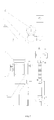
Figure 1 is a front view of the invention. -
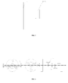
Figure 2 is a right view of the invention. -
Fig. 3 is a sectional view obtained along the A-A line of theFig. 1 . -
Figure 4 is an enlarged front view that an eccentric amount adjusting piece and a small shaft are assembled together. -
Figure 5 is an enlarged left view that an eccentric amount adjusting piece and a small shaft are assembled together. -
Figure 6 is a schematic diagram of eccentric amount change. -
Figure 7 is an enlarged front view of eccentricity. -
Figure 8 is an enlarged right view of eccentricity. - The embodiments of the invention shall be described in more details with the combination of the drawings and further illustrate the advantages of the invention and its contributions compared to the prior art. As shown in
Figure 1 andFigure 2 , the speed of a motor 6 is reduced through a worm speed reducer 7 so that the motor drives a shaft 1 to be rotated. The shaft 1 drives an eccentric transmission mechanism and a connectingrod mechanism 3 drawing anactive swing arm 4, and the fixed end of theactive swing arm 4 is moved around a rotation shaft 8. Anelectromagnet 10 is arranged on theactive swing arm 4 and drives a driven swing arm 9 after it is powered on. Agate leaf 5 is mounted on the driven swing arm 9, so as to open or close thegate leaf 5. Generally, when theactive swing arm 4 is under vertical conditions, the gate leaf has the maximum stroke. - Compared with the prior art, the invention mainly improves an eccentric transmission mechanism and a connecting
rod mechanism 3. As shown inFigures 3, 4 ,5, 6 ,7 and 8 , the shaft 1 and aneccentric disk 21 are fixed and connected through bolts, so as to transmit power. There is one eccentric amount between the axle line of the shaft 1 and the centric point of theeccentric disk 21 and the eccentric amount is unchanged. Theeccentric disk 21 is eccentrically provided in a mountedbase 212 of a round-shaped countersunk matched with a flange. The mountedbase 212 is provided with six mountedholes 211 of the eccentric disk positioned at the same periphery and spaced by the inclined angle of 60° uniformly. The flange is provided with three flange mountedholes 222 spaced by the inclined angle of 120° and is positioned at the mountedbase 212 of the countersunk. Theeccentric disk 21 and the flange are fixed and connected together through the bolts. Asmall shaft 223 is eccentrically fixed on the flange, and there is one eccentric amount A between the axle line of the small shaft and the centric point of the flange. When the mounted place between the flange and theeccentric disk 21 is changed, the distance between the axle lines of thesmall shaft 223 and the shaft 1 is changed, thus realizing the adjustment for the eccentricity. In the prior art, theeccentric disk 21 is directly welded with thesmall shaft 223 together, and the eccentric amount is a constant value and cannot be adjusted at this time. The invention is additionally provided with the flange and eccentrically provided with thesmall shaft 223 again. There is one eccentric amount A between thesmall shaft 223 and the central point of the flange. The flange is in bolted connection with theeccentric disk 21 through mounted holes. Therefore, only when the mounted place between the flange and theeccentric disk 21 is changed, the eccentric amount can be conveniently changed. Theeccentric disk 21 in the invention is provided with six mountedholes 211 of the eccentric disk spaced by the inclined angle of 60°. And then only when the flange is rotated by the angle of 60°, one eccentric amount can be changed. The flange has four places adjusting the eccentricity having respectively the inclined angles of 0°, 60°, 120°and 180°. As shown inFigure 6 , the maximum adjusting value of the eccentric amount is 2A. Therefore, the eccentric amount in the invention has very big adjusting room and then can be appropriately adapted for adjusting the length of the connecting rod. One end of atraction rod 33 of a right thread is provided with a bearing pedestal to fix aright bearing 37 and sleeved with asmall shaft 223, thus facilitating an eccentricamount adjusting piece 22 and a connectingrod mechanism 3 to be freely connected. The left and the right ends of the adjustingnut 31 are provided with a left thread and a right thread, and thetraction rods 32 and 33 of the left and the right threads are respectively connected with the left and the right threads of the adjustingnut 31. The right and the left lock nuts34 and 35 are arranged between thetraction rods 32 and 33 of the left and the right threads and the adjustingnut 31. Atraction shaft 41 is welded on anactive swing arm 4. Thetraction rod 31 of the left thread is provided with the bearing pedestal to fix theleft bearing 36 and sleeved with thetraction shaft 41, thereby facilitating thetraction rod 3 to be freely connected with theactive swing arm 4. - With the abovementioned arrangements, the invention adjusts the blocking width of a gate leaf within a certain range through such following steps: A mounted hole of a flange is firstly rotated and fixed on an
eccentric disk 21 with bolts after the mounted hole is adjusted to have proper eccentric amount. An adjustingnut 31 is rotated, and thetraction rods 32 and 33 of the left and the right threads are moved relatively, so as to increase or decrease the length of a connecting rod. After the length of the connecting rod is adjusted, the left and theright luck nuts 34 and 35 are screwed tightly. With the abovementioned adjustment, the blocking width of the gate leaf is changed and guarantees the gate leaf to be opened or recovered in place. In existing experiments, for example, the blocking width of 900mm can be adjusted to be 870mm.
| 1. | Shaft; | 3. | Connecting Rod Mechanism; |
| 4. | |
5. | Gate Leaf |
| 6. | Motor | 7. | Worm Speed Reducer |
| 8. | Rotation Shaft | 9. | |
| 10. | |
21. | |
| 22. | Eccentric Amount Adjusting |
||
| 31. | Adjusting Nut | ||
| 32. | Traction Rod of |
||
| 33. | Traction Rod of Right Thread | ||
| 34. | |
35. | |
| 36. | |
37. | |
| 41. | |
211. | Mounted Hole of |
| 212. | |
222. | Flange Mounted |
| 223. | Small Shaft |
Claims (6)
- A scissor-type gate blocking apparatus adjusting the blocking width of a gate leaf, comprising:a shaft (1);an active swing arm (4);wherein, the blocking apparatus also comprising:an eccentric disk (21) connected with the shaft (1) and eccentrically provided with a plurality of mounted holes (211) of the eccentric disk (21),an eccentric amount adjusting piece (22) connected with the eccentric disk (21) through the mounted holes (211) of the eccentric disk (21),a small shaft (223) eccentrically fixed at the eccentric amount adjusting piece (22); anda connecting rod mechanism (3) connected with the active swing arm 4 so as to adjust its length retractably.
- The scissor-type gate blocking apparatus adjusting the blocking width of the gate leaf according to claim 1, wherein six mounted holes (211) of the eccentric disk are distributed at the same periphery and spaced uniformly.
- The scissor-type gate blocking apparatus adjusting the blocking width of the gate leaf according to claim 1, wherein the eccentric amount adjusting piece (22) is a flange, and three flange mounted holes (222) are arranged on the flange, the flange mounted holes (222) are uniformly distributed and corresponding to the mounted holes (211) of the eccentric disk.
- The scissor-type gate blocking apparatus adjusting the blocking width of the gate leaf according to claim 1, wherein the connecting rod mechanism (3) comprises:an adjusting nut (31) having the left and the right ends respectively provided with a left thread and a right thread;a traction rod (32) of the left thread having one end connected with the left thread of the adjusting nut (31) and having the other end connected with the active swing arm (4) of the gate leaf; anda traction rod (33) of the right thread having one end connected with the right thread of the adjusting nut (31) and having the other end connected with the eccentric amount adjusting piece (22) .
- The scissor-type gate blocking apparatus adjusting the blocking width of the gate leaf according to claim 4, wherein the connecting rod mechanism (3) further comprises:a left lock nut (34) arranged between the traction rod (32) of the left thread and the adjusting nut (31); anda right lock nut (35) arranged between the traction rod (33) of the right thread and the adjusting nut (31).
- The scissor-type gate blocking apparatus adjusting the blocking width of the gate leaf according to claim 4, wherein
the active swing arm (4) is fixed with a traction shaft (41);
the traction rod (32) of the left thread is fixed with a left bearing (36) sleeved with the traction shaft (41), so as to facilitate the traction rod (32) of the left thread to be freely connected with the active swing arm (4); and
the traction rod (33) of the right thread is fixed with a right bearing (37) sleeved with the small shaft (223), so as to facilitate the traction rod (33) of the right thread to be freely connected with the active swing arm (22) of the eccentric amount adjusting piece (22).
Applications Claiming Priority (2)
| Application Number | Priority Date | Filing Date | Title |
|---|---|---|---|
| CN2010105970078A CN102108686B (en) | 2010-12-17 | 2010-12-17 | Shear type door arresting gear capable of regulating arresting width of fan doors |
| PCT/CN2011/000229 WO2012079271A1 (en) | 2010-12-17 | 2011-02-14 | Scissoring door block device with adjustable door block width |
Publications (3)
| Publication Number | Publication Date |
|---|---|
| EP2568080A1 true EP2568080A1 (en) | 2013-03-13 |
| EP2568080A4 EP2568080A4 (en) | 2016-05-18 |
| EP2568080B1 EP2568080B1 (en) | 2016-12-21 |
Family
ID=44172959
Family Applications (1)
| Application Number | Title | Priority Date | Filing Date |
|---|---|---|---|
| EP11849106.7A Not-in-force EP2568080B1 (en) | 2010-12-17 | 2011-02-14 | Scissoring door block device with adjustable door block width |
Country Status (5)
| Country | Link |
|---|---|
| US (1) | US8695276B2 (en) |
| EP (1) | EP2568080B1 (en) |
| CN (1) | CN102108686B (en) |
| MY (1) | MY165071A (en) |
| WO (1) | WO2012079271A1 (en) |
Cited By (2)
| Publication number | Priority date | Publication date | Assignee | Title |
|---|---|---|---|---|
| US10006246B2 (en) | 2013-07-30 | 2018-06-26 | Aegys, LLC | On demand modular ingress/egress control mechanism |
| CN109934938A (en) * | 2019-02-25 | 2019-06-25 | 深圳市玖品空气净化科技有限公司 | A kind of ticket-check equipment with anti-escape ticket function with block chain technology |
Families Citing this family (17)
| Publication number | Priority date | Publication date | Assignee | Title |
|---|---|---|---|---|
| CN103352440B (en) * | 2013-07-23 | 2015-11-04 | 浙江众合科技股份有限公司 | The gate that a kind of cam structure drives |
| CN103774590A (en) * | 2014-02-24 | 2014-05-07 | 浙江众合机电股份有限公司 | Elastic reset shear-type gate machine structure |
| CN106481181B (en) * | 2016-12-16 | 2018-11-06 | 广州新科佳都科技有限公司 | Fat pipe scissors fan door gear |
| CN106592464B (en) * | 2017-03-13 | 2022-04-08 | 深圳市西莫罗智能科技有限公司 | Novel swing gate with double coaxial cores |
| FR3069867B1 (en) * | 2017-08-01 | 2021-04-09 | Thales Sa | ASSEMBLY OF AUTOMATIC GATES INCLUDING SIGNIFICANTLY IDENTICAL MOTOR ASSEMBLIES AND PROCESS FOR PRODUCING SUCH ASSEMBLY |
| CN108532503A (en) * | 2018-03-19 | 2018-09-14 | 北京宝瑞达自动门科技有限公司 | A kind of gate door |
| CN108505929B (en) * | 2018-03-29 | 2019-07-19 | 滁州职业技术学院 | An access control system that prevents multiple people from entering and leaving at the same time |
| CN110397382B (en) * | 2018-07-27 | 2024-04-26 | 襄阳市思想机电科技有限公司 | A multi-link mechanism |
| CN212716344U (en) * | 2018-07-27 | 2021-03-16 | 襄阳市思想机电科技有限公司 | One-way door |
| CN108843171B (en) * | 2018-08-21 | 2023-10-20 | 普乐新能源(蚌埠)有限公司 | Transmission assembly of vacuum chamber door plate propelling device |
| US11047099B2 (en) * | 2018-09-14 | 2021-06-29 | Koei Industry Co., Ltd. | Pass blocking apparatus |
| WO2020077973A1 (en) * | 2018-10-15 | 2020-04-23 | 上海华铭智能终端设备股份有限公司 | Opening/closing device for gate passage |
| CN110080130A (en) * | 2019-05-21 | 2019-08-02 | 深圳市德宝智能科技有限公司 | Upper and lower motivation cored structure |
| USD1105482S1 (en) * | 2019-07-29 | 2025-12-09 | Magnetic Autocontrol Gmbh | Access control gate |
| CN111877212A (en) * | 2020-07-31 | 2020-11-03 | 朱佳甜 | Isolation entrance guard equipment |
| CN112150794B (en) * | 2020-10-15 | 2021-10-26 | 江苏博子岛智能产业技术研究院有限公司 | Crossroad pedestrian red light running traffic monitoring device |
| EP4571038A1 (en) | 2023-12-14 | 2025-06-18 | By Techdesign S.L. | Advanced automatic passageway for controlling pedestrian access |
Family Cites Families (13)
| Publication number | Priority date | Publication date | Assignee | Title |
|---|---|---|---|---|
| JPH08221613A (en) * | 1995-02-08 | 1996-08-30 | Tsutomu Takita | Automatic ticket examining machine |
| JP2000132956A (en) * | 1998-10-23 | 2000-05-12 | Pioneer Electronic Corp | Vehicle-mounted equipment |
| DE10019957A1 (en) * | 2000-04-20 | 2001-10-25 | Magnetic Autocontrol Gmbh | Barrier appliance to close-off roadways and enclosed rooms has brush-less DC motor with Hall sensors to determine all positions of a barrier |
| JP4261208B2 (en) * | 2003-02-03 | 2009-04-30 | 日本信号株式会社 | Door drive for automatic ticket gate |
| CN2635850Y (en) * | 2003-02-27 | 2004-08-25 | 上海华铭智能终端设备有限公司 | Door leaf guard controller |
| DE202005015373U1 (en) * | 2005-09-29 | 2005-12-15 | Magnetic Autocontrol Gmbh | Rotary sector barrier controlling individual access, include circular sectors pivoting about common floor-level axis, actuated by drive motor and levers |
| JP4749859B2 (en) * | 2005-12-28 | 2011-08-17 | 千蔵工業株式会社 | Automatic gate device |
| US7862252B2 (en) * | 2006-04-10 | 2011-01-04 | Universal Safety Response, Inc. | Vehicle barrier system |
| CN201053282Y (en) * | 2007-04-25 | 2008-04-30 | 深圳现代信息技术有限公司 | Shear-type door structure for ticket checking machine |
| CN201037352Y (en) * | 2007-06-05 | 2008-03-19 | 上海华铭智能终端设备有限公司 | Automatic ticket checking machine scissor-type door device |
| CN201110102Y (en) * | 2007-10-26 | 2008-09-03 | 上海华铭智能终端设备有限公司 | Wide channel shear type door apparatus of automatic checking machine |
| CN101418651B (en) * | 2007-10-26 | 2011-01-26 | 上海华铭智能终端设备有限公司 | Wide-passage shear type door mechanism for automatic ticket checking machine |
| US7818920B2 (en) * | 2007-11-06 | 2010-10-26 | Causey Lynn R | Barrier gate with torque limiter |
-
2010
- 2010-12-17 CN CN2010105970078A patent/CN102108686B/en active Active
-
2011
- 2011-02-14 US US13/703,885 patent/US8695276B2/en active Active
- 2011-02-14 MY MYPI2012700713A patent/MY165071A/en unknown
- 2011-02-14 WO PCT/CN2011/000229 patent/WO2012079271A1/en not_active Ceased
- 2011-02-14 EP EP11849106.7A patent/EP2568080B1/en not_active Not-in-force
Non-Patent Citations (1)
| Title |
|---|
| See references of WO2012079271A1 * |
Cited By (2)
| Publication number | Priority date | Publication date | Assignee | Title |
|---|---|---|---|---|
| US10006246B2 (en) | 2013-07-30 | 2018-06-26 | Aegys, LLC | On demand modular ingress/egress control mechanism |
| CN109934938A (en) * | 2019-02-25 | 2019-06-25 | 深圳市玖品空气净化科技有限公司 | A kind of ticket-check equipment with anti-escape ticket function with block chain technology |
Also Published As
| Publication number | Publication date |
|---|---|
| MY165071A (en) | 2018-02-28 |
| CN102108686A (en) | 2011-06-29 |
| US20130269260A1 (en) | 2013-10-17 |
| EP2568080B1 (en) | 2016-12-21 |
| EP2568080A4 (en) | 2016-05-18 |
| US8695276B2 (en) | 2014-04-15 |
| CN102108686B (en) | 2012-05-02 |
| WO2012079271A1 (en) | 2012-06-21 |
Similar Documents
| Publication | Publication Date | Title |
|---|---|---|
| EP2568080B1 (en) | Scissoring door block device with adjustable door block width | |
| CN110517395A (en) | A kind of human face identification work-attendance checking gate | |
| CN112247884B (en) | Adjustable clamping device for machining safety door frame | |
| CN110838683A (en) | Safe explosion-proof type high-low voltage power distribution cabinet | |
| CN205823008U (en) | A kind of drive mechanism for vehicle double open plug door system | |
| CN105804593B (en) | A kind of translation door linkage control method and linkage type translation door | |
| CN218493405U (en) | Hidden electric driving system for sliding door and window | |
| CN207891786U (en) | Integral type speed open gate cassette mechanism structure and gate | |
| CN112299212B (en) | An elevator door lock with adjustable oblique travel angle | |
| CN206386647U (en) | A kind of campus monitoring probe for being easy to manage | |
| CN212507947U (en) | Sliding mechanism with anti-blocking structure for bus shielding door | |
| CN202055201U (en) | Scissor-like door blocking device enabling adjusting blocking width of leaf door | |
| CN207698556U (en) | A kind of tailgate feed device for opening flat machine | |
| CN202590726U (en) | Discharge door control mechanism of mixing machine | |
| CN207598093U (en) | Automatic door and window machine actuating device, automatic door and window machine and door and window | |
| CN209323421U (en) | A kind of flap turnstile machine core | |
| CN208856797U (en) | A kind of prefabricated PC component molding suspender | |
| CN217267092U (en) | Pedestrian passageway gate quick-passing gate swing gate | |
| CN212200168U (en) | Security protection floodgate machine servo drive device | |
| CN205224936U (en) | Opening device is tied to national treasury every | |
| DE19735602C1 (en) | Drive for e.g. sliding doors, windows and partitions running on rails | |
| CN221483186U (en) | Monitoring device with steering function | |
| CN211736830U (en) | Moving mechanism of sliding door | |
| CN221169186U (en) | Automatic swing arm actuating mechanism opens door | |
| CN216767084U (en) | Subway platform door is whole to open and close door control backup device |
Legal Events
| Date | Code | Title | Description |
|---|---|---|---|
| PUAI | Public reference made under article 153(3) epc to a published international application that has entered the european phase |
Free format text: ORIGINAL CODE: 0009012 |
|
| 17P | Request for examination filed |
Effective date: 20121205 |
|
| AK | Designated contracting states |
Kind code of ref document: A1 Designated state(s): AL AT BE BG CH CY CZ DE DK EE ES FI FR GB GR HR HU IE IS IT LI LT LU LV MC MK MT NL NO PL PT RO RS SE SI SK SM TR |
|
| DAX | Request for extension of the european patent (deleted) | ||
| RA4 | Supplementary search report drawn up and despatched (corrected) |
Effective date: 20160420 |
|
| RIC1 | Information provided on ipc code assigned before grant |
Ipc: E01F 13/04 20060101AFI20160414BHEP Ipc: G07B 11/00 20060101ALI20160414BHEP Ipc: E05F 15/611 20150101ALI20160414BHEP |
|
| GRAP | Despatch of communication of intention to grant a patent |
Free format text: ORIGINAL CODE: EPIDOSNIGR1 |
|
| INTG | Intention to grant announced |
Effective date: 20160926 |
|
| GRAS | Grant fee paid |
Free format text: ORIGINAL CODE: EPIDOSNIGR3 |
|
| GRAA | (expected) grant |
Free format text: ORIGINAL CODE: 0009210 |
|
| AK | Designated contracting states |
Kind code of ref document: B1 Designated state(s): AL AT BE BG CH CY CZ DE DK EE ES FI FR GB GR HR HU IE IS IT LI LT LU LV MC MK MT NL NO PL PT RO RS SE SI SK SM TR |
|
| REG | Reference to a national code |
Ref country code: GB Ref legal event code: FG4D |
|
| REG | Reference to a national code |
Ref country code: CH Ref legal event code: EP |
|
| REG | Reference to a national code |
Ref country code: IE Ref legal event code: FG4D |
|
| REG | Reference to a national code |
Ref country code: AT Ref legal event code: REF Ref document number: 855629 Country of ref document: AT Kind code of ref document: T Effective date: 20170115 |
|
| REG | Reference to a national code |
Ref country code: DE Ref legal event code: R096 Ref document number: 602011033724 Country of ref document: DE |
|
| REG | Reference to a national code |
Ref country code: FR Ref legal event code: PLFP Year of fee payment: 7 |
|
| PG25 | Lapsed in a contracting state [announced via postgrant information from national office to epo] |
Ref country code: LV Free format text: LAPSE BECAUSE OF FAILURE TO SUBMIT A TRANSLATION OF THE DESCRIPTION OR TO PAY THE FEE WITHIN THE PRESCRIBED TIME-LIMIT Effective date: 20161221 |
|
| REG | Reference to a national code |
Ref country code: LT Ref legal event code: MG4D |
|
| REG | Reference to a national code |
Ref country code: NL Ref legal event code: MP Effective date: 20161221 |
|
| PG25 | Lapsed in a contracting state [announced via postgrant information from national office to epo] |
Ref country code: LT Free format text: LAPSE BECAUSE OF FAILURE TO SUBMIT A TRANSLATION OF THE DESCRIPTION OR TO PAY THE FEE WITHIN THE PRESCRIBED TIME-LIMIT Effective date: 20161221 Ref country code: SE Free format text: LAPSE BECAUSE OF FAILURE TO SUBMIT A TRANSLATION OF THE DESCRIPTION OR TO PAY THE FEE WITHIN THE PRESCRIBED TIME-LIMIT Effective date: 20161221 Ref country code: GR Free format text: LAPSE BECAUSE OF FAILURE TO SUBMIT A TRANSLATION OF THE DESCRIPTION OR TO PAY THE FEE WITHIN THE PRESCRIBED TIME-LIMIT Effective date: 20170322 Ref country code: NO Free format text: LAPSE BECAUSE OF FAILURE TO SUBMIT A TRANSLATION OF THE DESCRIPTION OR TO PAY THE FEE WITHIN THE PRESCRIBED TIME-LIMIT Effective date: 20170321 |
|
| REG | Reference to a national code |
Ref country code: AT Ref legal event code: MK05 Ref document number: 855629 Country of ref document: AT Kind code of ref document: T Effective date: 20161221 |
|
| PG25 | Lapsed in a contracting state [announced via postgrant information from national office to epo] |
Ref country code: FI Free format text: LAPSE BECAUSE OF FAILURE TO SUBMIT A TRANSLATION OF THE DESCRIPTION OR TO PAY THE FEE WITHIN THE PRESCRIBED TIME-LIMIT Effective date: 20161221 Ref country code: HR Free format text: LAPSE BECAUSE OF FAILURE TO SUBMIT A TRANSLATION OF THE DESCRIPTION OR TO PAY THE FEE WITHIN THE PRESCRIBED TIME-LIMIT Effective date: 20161221 Ref country code: RS Free format text: LAPSE BECAUSE OF FAILURE TO SUBMIT A TRANSLATION OF THE DESCRIPTION OR TO PAY THE FEE WITHIN THE PRESCRIBED TIME-LIMIT Effective date: 20161221 Ref country code: BE Free format text: LAPSE BECAUSE OF NON-PAYMENT OF DUE FEES Effective date: 20170228 |
|
| PG25 | Lapsed in a contracting state [announced via postgrant information from national office to epo] |
Ref country code: NL Free format text: LAPSE BECAUSE OF FAILURE TO SUBMIT A TRANSLATION OF THE DESCRIPTION OR TO PAY THE FEE WITHIN THE PRESCRIBED TIME-LIMIT Effective date: 20161221 |
|
| PG25 | Lapsed in a contracting state [announced via postgrant information from national office to epo] |
Ref country code: SK Free format text: LAPSE BECAUSE OF FAILURE TO SUBMIT A TRANSLATION OF THE DESCRIPTION OR TO PAY THE FEE WITHIN THE PRESCRIBED TIME-LIMIT Effective date: 20161221 Ref country code: EE Free format text: LAPSE BECAUSE OF FAILURE TO SUBMIT A TRANSLATION OF THE DESCRIPTION OR TO PAY THE FEE WITHIN THE PRESCRIBED TIME-LIMIT Effective date: 20161221 Ref country code: IS Free format text: LAPSE BECAUSE OF FAILURE TO SUBMIT A TRANSLATION OF THE DESCRIPTION OR TO PAY THE FEE WITHIN THE PRESCRIBED TIME-LIMIT Effective date: 20170421 Ref country code: CZ Free format text: LAPSE BECAUSE OF FAILURE TO SUBMIT A TRANSLATION OF THE DESCRIPTION OR TO PAY THE FEE WITHIN THE PRESCRIBED TIME-LIMIT Effective date: 20161221 Ref country code: RO Free format text: LAPSE BECAUSE OF FAILURE TO SUBMIT A TRANSLATION OF THE DESCRIPTION OR TO PAY THE FEE WITHIN THE PRESCRIBED TIME-LIMIT Effective date: 20161221 |
|
| PG25 | Lapsed in a contracting state [announced via postgrant information from national office to epo] |
Ref country code: BE Free format text: LAPSE BECAUSE OF FAILURE TO SUBMIT A TRANSLATION OF THE DESCRIPTION OR TO PAY THE FEE WITHIN THE PRESCRIBED TIME-LIMIT Effective date: 20161221 Ref country code: PL Free format text: LAPSE BECAUSE OF FAILURE TO SUBMIT A TRANSLATION OF THE DESCRIPTION OR TO PAY THE FEE WITHIN THE PRESCRIBED TIME-LIMIT Effective date: 20161221 Ref country code: IT Free format text: LAPSE BECAUSE OF FAILURE TO SUBMIT A TRANSLATION OF THE DESCRIPTION OR TO PAY THE FEE WITHIN THE PRESCRIBED TIME-LIMIT Effective date: 20161221 Ref country code: SM Free format text: LAPSE BECAUSE OF FAILURE TO SUBMIT A TRANSLATION OF THE DESCRIPTION OR TO PAY THE FEE WITHIN THE PRESCRIBED TIME-LIMIT Effective date: 20161221 Ref country code: BG Free format text: LAPSE BECAUSE OF FAILURE TO SUBMIT A TRANSLATION OF THE DESCRIPTION OR TO PAY THE FEE WITHIN THE PRESCRIBED TIME-LIMIT Effective date: 20170321 Ref country code: ES Free format text: LAPSE BECAUSE OF FAILURE TO SUBMIT A TRANSLATION OF THE DESCRIPTION OR TO PAY THE FEE WITHIN THE PRESCRIBED TIME-LIMIT Effective date: 20161221 Ref country code: AT Free format text: LAPSE BECAUSE OF FAILURE TO SUBMIT A TRANSLATION OF THE DESCRIPTION OR TO PAY THE FEE WITHIN THE PRESCRIBED TIME-LIMIT Effective date: 20161221 Ref country code: PT Free format text: LAPSE BECAUSE OF FAILURE TO SUBMIT A TRANSLATION OF THE DESCRIPTION OR TO PAY THE FEE WITHIN THE PRESCRIBED TIME-LIMIT Effective date: 20170421 |
|
| REG | Reference to a national code |
Ref country code: DE Ref legal event code: R097 Ref document number: 602011033724 Country of ref document: DE |
|
| PG25 | Lapsed in a contracting state [announced via postgrant information from national office to epo] |
Ref country code: MC Free format text: LAPSE BECAUSE OF FAILURE TO SUBMIT A TRANSLATION OF THE DESCRIPTION OR TO PAY THE FEE WITHIN THE PRESCRIBED TIME-LIMIT Effective date: 20161221 |
|
| REG | Reference to a national code |
Ref country code: CH Ref legal event code: PL |
|
| PLBE | No opposition filed within time limit |
Free format text: ORIGINAL CODE: 0009261 |
|
| STAA | Information on the status of an ep patent application or granted ep patent |
Free format text: STATUS: NO OPPOSITION FILED WITHIN TIME LIMIT |
|
| PG25 | Lapsed in a contracting state [announced via postgrant information from national office to epo] |
Ref country code: CH Free format text: LAPSE BECAUSE OF NON-PAYMENT OF DUE FEES Effective date: 20170228 Ref country code: LI Free format text: LAPSE BECAUSE OF NON-PAYMENT OF DUE FEES Effective date: 20170228 |
|
| 26N | No opposition filed |
Effective date: 20170922 |
|
| PG25 | Lapsed in a contracting state [announced via postgrant information from national office to epo] |
Ref country code: DK Free format text: LAPSE BECAUSE OF FAILURE TO SUBMIT A TRANSLATION OF THE DESCRIPTION OR TO PAY THE FEE WITHIN THE PRESCRIBED TIME-LIMIT Effective date: 20161221 |
|
| PG25 | Lapsed in a contracting state [announced via postgrant information from national office to epo] |
Ref country code: LU Free format text: LAPSE BECAUSE OF NON-PAYMENT OF DUE FEES Effective date: 20170214 |
|
| REG | Reference to a national code |
Ref country code: FR Ref legal event code: PLFP Year of fee payment: 8 |
|
| PG25 | Lapsed in a contracting state [announced via postgrant information from national office to epo] |
Ref country code: SI Free format text: LAPSE BECAUSE OF FAILURE TO SUBMIT A TRANSLATION OF THE DESCRIPTION OR TO PAY THE FEE WITHIN THE PRESCRIBED TIME-LIMIT Effective date: 20161221 |
|
| PG25 | Lapsed in a contracting state [announced via postgrant information from national office to epo] |
Ref country code: MT Free format text: LAPSE BECAUSE OF NON-PAYMENT OF DUE FEES Effective date: 20170214 |
|
| PG25 | Lapsed in a contracting state [announced via postgrant information from national office to epo] |
Ref country code: HU Free format text: LAPSE BECAUSE OF FAILURE TO SUBMIT A TRANSLATION OF THE DESCRIPTION OR TO PAY THE FEE WITHIN THE PRESCRIBED TIME-LIMIT; INVALID AB INITIO Effective date: 20110214 |
|
| PG25 | Lapsed in a contracting state [announced via postgrant information from national office to epo] |
Ref country code: CY Free format text: LAPSE BECAUSE OF NON-PAYMENT OF DUE FEES Effective date: 20161221 |
|
| PG25 | Lapsed in a contracting state [announced via postgrant information from national office to epo] |
Ref country code: MK Free format text: LAPSE BECAUSE OF FAILURE TO SUBMIT A TRANSLATION OF THE DESCRIPTION OR TO PAY THE FEE WITHIN THE PRESCRIBED TIME-LIMIT Effective date: 20161221 |
|
| PG25 | Lapsed in a contracting state [announced via postgrant information from national office to epo] |
Ref country code: TR Free format text: LAPSE BECAUSE OF FAILURE TO SUBMIT A TRANSLATION OF THE DESCRIPTION OR TO PAY THE FEE WITHIN THE PRESCRIBED TIME-LIMIT Effective date: 20161221 |
|
| PG25 | Lapsed in a contracting state [announced via postgrant information from national office to epo] |
Ref country code: AL Free format text: LAPSE BECAUSE OF FAILURE TO SUBMIT A TRANSLATION OF THE DESCRIPTION OR TO PAY THE FEE WITHIN THE PRESCRIBED TIME-LIMIT Effective date: 20161221 |
|
| PGFP | Annual fee paid to national office [announced via postgrant information from national office to epo] |
Ref country code: IE Payment date: 20220216 Year of fee payment: 12 Ref country code: GB Payment date: 20220221 Year of fee payment: 12 Ref country code: DE Payment date: 20220105 Year of fee payment: 12 |
|
| PGFP | Annual fee paid to national office [announced via postgrant information from national office to epo] |
Ref country code: FR Payment date: 20220221 Year of fee payment: 12 |
|
| REG | Reference to a national code |
Ref country code: DE Ref legal event code: R119 Ref document number: 602011033724 Country of ref document: DE |
|
| GBPC | Gb: european patent ceased through non-payment of renewal fee |
Effective date: 20230214 |
|
| REG | Reference to a national code |
Ref country code: IE Ref legal event code: MM4A |
|
| PG25 | Lapsed in a contracting state [announced via postgrant information from national office to epo] |
Ref country code: GB Free format text: LAPSE BECAUSE OF NON-PAYMENT OF DUE FEES Effective date: 20230214 |
|
| PG25 | Lapsed in a contracting state [announced via postgrant information from national office to epo] |
Ref country code: IE Free format text: LAPSE BECAUSE OF NON-PAYMENT OF DUE FEES Effective date: 20230214 Ref country code: GB Free format text: LAPSE BECAUSE OF NON-PAYMENT OF DUE FEES Effective date: 20230214 Ref country code: FR Free format text: LAPSE BECAUSE OF NON-PAYMENT OF DUE FEES Effective date: 20230228 Ref country code: DE Free format text: LAPSE BECAUSE OF NON-PAYMENT OF DUE FEES Effective date: 20230901 |