EP2567853A2 - Halterungselement zur Befestigung eines Elektromotors auf einer elektronischen Leiterplatte, Anzeigeeinrichtung eines Kraftfahrzeugs umfassend ein elektrisches Zeigerinstrument mit einem mittels eines solchen Halterungselements auf einer elektronischen Leiterplatte befestigten Elektromotors sowie Verfahren zur Befestigung eines Elektromotors auf einer elektronischen Leiterplatte mittels eines solchen Halterungselements - Google Patents
Halterungselement zur Befestigung eines Elektromotors auf einer elektronischen Leiterplatte, Anzeigeeinrichtung eines Kraftfahrzeugs umfassend ein elektrisches Zeigerinstrument mit einem mittels eines solchen Halterungselements auf einer elektronischen Leiterplatte befestigten Elektromotors sowie Verfahren zur Befestigung eines Elektromotors auf einer elektronischen Leiterplatte mittels eines solchen Halterungselements Download PDFInfo
- Publication number
- EP2567853A2 EP2567853A2 EP12171626A EP12171626A EP2567853A2 EP 2567853 A2 EP2567853 A2 EP 2567853A2 EP 12171626 A EP12171626 A EP 12171626A EP 12171626 A EP12171626 A EP 12171626A EP 2567853 A2 EP2567853 A2 EP 2567853A2
- Authority
- EP
- European Patent Office
- Prior art keywords
- circuit board
- electric motor
- support member
- contact elements
- pointer
- Prior art date
- Legal status (The legal status is an assumption and is not a legal conclusion. Google has not performed a legal analysis and makes no representation as to the accuracy of the status listed.)
- Granted
Links
Images

Classifications
-
- H—ELECTRICITY
- H05—ELECTRIC TECHNIQUES NOT OTHERWISE PROVIDED FOR
- H05K—PRINTED CIRCUITS; CASINGS OR CONSTRUCTIONAL DETAILS OF ELECTRIC APPARATUS; MANUFACTURE OF ASSEMBLAGES OF ELECTRICAL COMPONENTS
- H05K3/00—Apparatus or processes for manufacturing printed circuits
- H05K3/30—Assembling printed circuits with electric components, e.g. with resistors
- H05K3/301—Assembling printed circuits with electric components, e.g. with resistors by means of a mounting structure
-
- B—PERFORMING OPERATIONS; TRANSPORTING
- B60—VEHICLES IN GENERAL
- B60K—ARRANGEMENT OR MOUNTING OF PROPULSION UNITS OR OF TRANSMISSIONS IN VEHICLES; ARRANGEMENT OR MOUNTING OF PLURAL DIVERSE PRIME-MOVERS IN VEHICLES; AUXILIARY DRIVES FOR VEHICLES; INSTRUMENTATION OR DASHBOARDS FOR VEHICLES; ARRANGEMENTS IN CONNECTION WITH COOLING, AIR INTAKE, GAS EXHAUST OR FUEL SUPPLY OF PROPULSION UNITS IN VEHICLES
- B60K35/00—Instruments specially adapted for vehicles; Arrangement of instruments in or on vehicles
- B60K35/50—Instruments characterised by their means of attachment to or integration in the vehicle
-
- B—PERFORMING OPERATIONS; TRANSPORTING
- B60—VEHICLES IN GENERAL
- B60K—ARRANGEMENT OR MOUNTING OF PROPULSION UNITS OR OF TRANSMISSIONS IN VEHICLES; ARRANGEMENT OR MOUNTING OF PLURAL DIVERSE PRIME-MOVERS IN VEHICLES; AUXILIARY DRIVES FOR VEHICLES; INSTRUMENTATION OR DASHBOARDS FOR VEHICLES; ARRANGEMENTS IN CONNECTION WITH COOLING, AIR INTAKE, GAS EXHAUST OR FUEL SUPPLY OF PROPULSION UNITS IN VEHICLES
- B60K2360/00—Indexing scheme associated with groups B60K35/00 or B60K37/00 relating to details of instruments or dashboards
- B60K2360/40—Hardware adaptations for dashboards or instruments
- B60K2360/42—Circuit board features
-
- B—PERFORMING OPERATIONS; TRANSPORTING
- B60—VEHICLES IN GENERAL
- B60K—ARRANGEMENT OR MOUNTING OF PROPULSION UNITS OR OF TRANSMISSIONS IN VEHICLES; ARRANGEMENT OR MOUNTING OF PLURAL DIVERSE PRIME-MOVERS IN VEHICLES; AUXILIARY DRIVES FOR VEHICLES; INSTRUMENTATION OR DASHBOARDS FOR VEHICLES; ARRANGEMENTS IN CONNECTION WITH COOLING, AIR INTAKE, GAS EXHAUST OR FUEL SUPPLY OF PROPULSION UNITS IN VEHICLES
- B60K2360/00—Indexing scheme associated with groups B60K35/00 or B60K37/00 relating to details of instruments or dashboards
- B60K2360/60—Structural details of dashboards or instruments
- B60K2360/68—Features of instruments
- B60K2360/698—Pointers of combined instruments
-
- G—PHYSICS
- G01—MEASURING; TESTING
- G01D—MEASURING NOT SPECIALLY ADAPTED FOR A SPECIFIC VARIABLE; ARRANGEMENTS FOR MEASURING TWO OR MORE VARIABLES NOT COVERED IN A SINGLE OTHER SUBCLASS; TARIFF METERING APPARATUS; MEASURING OR TESTING NOT OTHERWISE PROVIDED FOR
- G01D11/00—Component parts of measuring arrangements not specially adapted for a specific variable
- G01D11/30—Supports specially adapted for an instrument; Supports specially adapted for a set of instruments
- G01D11/305—Panel mounting of instruments
-
- H—ELECTRICITY
- H05—ELECTRIC TECHNIQUES NOT OTHERWISE PROVIDED FOR
- H05K—PRINTED CIRCUITS; CASINGS OR CONSTRUCTIONAL DETAILS OF ELECTRIC APPARATUS; MANUFACTURE OF ASSEMBLAGES OF ELECTRICAL COMPONENTS
- H05K2201/00—Indexing scheme relating to printed circuits covered by H05K1/00
- H05K2201/10—Details of components or other objects attached to or integrated in a printed circuit board
- H05K2201/10007—Types of components
- H05K2201/1009—Electromotor
-
- H—ELECTRICITY
- H05—ELECTRIC TECHNIQUES NOT OTHERWISE PROVIDED FOR
- H05K—PRINTED CIRCUITS; CASINGS OR CONSTRUCTIONAL DETAILS OF ELECTRIC APPARATUS; MANUFACTURE OF ASSEMBLAGES OF ELECTRICAL COMPONENTS
- H05K2201/00—Indexing scheme relating to printed circuits covered by H05K1/00
- H05K2201/10—Details of components or other objects attached to or integrated in a printed circuit board
- H05K2201/10431—Details of mounted components
- H05K2201/10439—Position of a single component
- H05K2201/10484—Obliquely mounted
-
- H—ELECTRICITY
- H05—ELECTRIC TECHNIQUES NOT OTHERWISE PROVIDED FOR
- H05K—PRINTED CIRCUITS; CASINGS OR CONSTRUCTIONAL DETAILS OF ELECTRIC APPARATUS; MANUFACTURE OF ASSEMBLAGES OF ELECTRICAL COMPONENTS
- H05K3/00—Apparatus or processes for manufacturing printed circuits
- H05K3/30—Assembling printed circuits with electric components, e.g. with resistors
- H05K3/306—Assembling printed circuits with electric components, e.g. with resistors with lead-in-hole components
Definitions
- the present invention relates to a support member for fixing an electric motor on an electronic circuit board of an electrical pointer instrument, wherein the electric motor drives a pointer of the pointer instrument via a motor shaft. Furthermore, the invention relates to a display device of a motor vehicle comprising at least one electric pointer instrument with at least one driven by an electric motor pointer, wherein the Electric motor is mounted on an electronic circuit board and electrically contacted via this and has a motor shaft to which the at least one pointer of the at least one pointer instrument is attached. Finally, the present invention also relates to a method for mounting an electric motor on an electronic circuit board of an electrical pointer instrument, wherein the electric motor drives a pointer of the pointer instrument via a motor shaft.
- Such display devices have at least one pointer instrument, which comprises at least one pointer driven in each case by an electric motor.
- the pointer instrument further has a display area provided with a scale, wherein preferably each pointer of a pointer instrument is assigned its own scale.
- Such pointer instruments are also referred to as analog instruments.
- the pointer instruments are used in motor vehicles, for example, to display the current vehicle speed (speedometer), the current engine speed (tachometer), the tank contents, the battery voltage, the boost pressure of a turbocharger or compressor, the oil temperature, the oil pressure, the outside temperature, the cooling water temperature, etc.
- the individual pointer instruments or their display surfaces are often arranged directed around the driver's position around the driver, so that there is a curved around the driver instrument cluster.
- the electronic circuit including all electrical and electronic components and the electric motors for driving the pointer of all pointer instruments of a display device on a single electronic circuit board.
- An appropriate attachment of an electric motor on a circuit board by means of a support member is, for example, from the DE 42 09 823 A1 or the CN 2725083 Y known.
- the present invention is based on the object, in curved display devices in which the display surfaces of the individual pointer instruments are at least partially inclined to each other, all electric motors for actuating the hands of the pointer instruments on a single planar rigid electronic circuit board to arrange.
- the support member has first attachment means for fixing the support member on the circuit board and second attachment means for fixing the electric motor to the support member, wherein the first and second attachment means of the support member formed and are arranged relative to each other, that the electric motor is mounted with extending obliquely to a surface extension of the circuit board extending motor shaft on the circuit board.
- the mounting element with which the electric motor is mounted on the electronic circuit board or board and electrically contacted in such a way that an oblique attachment of the electric motor on the circuit board is possible.
- the support member is configured depending on the desired angle of inclination of the electric motor relative to the circuit board.
- a first electric motor with a motor shaft inclined to the right and, on the other hand, another electric motor with a motor shaft inclined to the left can be fastened to the printed circuit board.
- different support members are provided for different angles of inclination of the electric motor relative to the circuit board.
- the arrangement of all electric motors on a single, planar, rigid circuit board applies not only during assembly and assembly of the circuit board, but also when the assembled circuit board is installed in an operative position in the display device and the display device is in a ready state.
- the support elements are arranged together with the other electrical and electronic components in the assembly of the circuit board on this and, for example, in the context of a soldering process, in particular a reflow soldering process, mounted on this and electrically contacted.
- the electric motors can be attached to the support elements.
- the electric motors are preferably also contacted electrically simultaneously with the attachment in the support elements. In this way, the electric motors can be mechanically fastened in a single step on the one hand to the support elements and simultaneously contacted electrically.
- the present invention allows mounting of the electric motors obliquely to the surface extension of the electronic circuit board. This makes it possible for the first time in curved display devices with a plurality of relatively inclined pointer instruments or each other inclined scaled display surfaces of the pointer instruments to attach the pointer instruments associated electric motors on a single common, planar, rigid circuit board. This has considerable advantages both in the assembly of the circuit board and in the assembly of the display device, in particular when inserting the assembled printed circuit board with the components mounted thereon and electrically contacted. With the present invention, curved display devices of a motor vehicle can be realized simply and inexpensively, at the same time significantly reducing the production outlay.
- the first fastening means are designed such that they allow attachment of the retaining element on the printed circuit board by means of a soldering process, in particular a reflow soldering process.
- the holding element preferably has contact elements which, when the holding element is arranged on the printed circuit board, engage with corresponding contacting means of the printed circuit board and ensure electrical contacting of the holding element at least after the soldering process.
- the contact elements may, for example, be designed as plug-in contact elements or as spring contact elements.
- the contacting means may be formed as contacting holes formed in the printed circuit board or pads formed on the printed circuit board.
- the plug contact elements are used with contacting holes and the spring contact elements with contacting surfaces.
- the contacting means of the printed circuit board are formed as contacting holes, which receive contact elements formed as plug-in contact elements of the support member arranged on the circuit board support member, so that the plug contact elements the holding element can be contacted and fastened in the contacting holes of the printed circuit board by means of the soldering process, in particular the reflow soldering process.
- the contacting means of the printed circuit board may also be formed as contacting surfaces which receive contact elements of the holding element arranged as spring contact elements with the holding element arranged on the printed circuit board, so that the spring contact elements of the holding element can be contacted and fastened to the contacting surfaces of the printed circuit board by means of the soldering process, in particular the reflow soldering process are.
- the contacting means of the printed circuit board with the holding element arranged on the printed circuit board preferably automatically or positively absorb the (surface or plug) contact elements of the holding element, so that there is no need for an additional working step for producing the electrical contact.
- the support member is advantageously also contacted and secured in a similar manner as other electronic and electrical components and components in the context of a reflow soldering process on the electronic circuit board.
- the second fastening means are designed such that they allow a releasable attachment of the electric motor to the support member.
- the second fastening means are advantageously designed such that they allow attachment of the electric motor to the support member by means of a snap or latching connection. This allows the electric motor following the soldering process, in particular the
- the holding element has contact elements which are designed and arranged such that, when the electric motor is fastened to the holding element, they engage with corresponding contact elements of the electric motor and provide electrical contact with the electric motor.
- the contact elements of the support member are electrically contacted via the circuit board, for example.
- the contact elements of the support member are, for example, designed as plug, spring or surface contact elements.
- the corresponding contact elements of the electric motor are accordingly, for example, designed as plug, surface or spring contact elements.
- the contact elements of the support member and the electric motor are designed as plug-in contact elements, wherein the plug contact elements of the support member are formed as socket contact elements with which the pin contact elements designed as corresponding plug contact elements of the electric motor engage when the electric motor is inserted into the support member.
- the electric motor is also electrically contacted simultaneously with the attachment to the support member by entering the pin contact elements of the electric motor in the corresponding female contact elements of the support member, where automatically an electrical contact between the female contact elements and the pin contact elements is made. This allows a particularly simple and time-efficient attachment and contacting of the electric motor to the support member.
- the socket contact elements are formed on the electric motor and the corresponding pin contact elements on the support member or that the electric motor is not releasably secured to the support member.
- the support member is part of a housing of the electric motor, that is an integral part of the electric motor housing. In this case, either the electric motor would have to be able to withstand the thermal loads of the reflow soldering process or the electric motor-mounting element combination is attached to the electronic circuit board and electrically contacted only after the reflow soldering process, for example by means of any other soldering process. Even if the support member is an integral part of the motor housing, it allows due to the inventive design an oblique mounting of the electric motor on the electronic circuit board.
- the present invention is also a display device of a motor vehicle of the aforementioned type, wherein the electric motor is secured by means of a support member on the electronic circuit board such that the motor shaft extends obliquely to a surface extension of the circuit board.
- the support member is formed as a separate component separated from a housing of the electric motor.
- a display device in which the electric motor is fastened by means of a support element according to the invention on the circuit board and optionally electrically contacted.
- the present invention also relates to a method for mounting an electric motor on an electronic circuit board of the aforementioned type, wherein first a support member is attached via first attachment means of the support member on the circuit board and then the electric motor via second attachment means of the support member is fixed to the support member, wherein the first and second attachment means of the support member are formed and arranged relative to each other, that the electric motor with obliquely to a surface extension of the circuit board extending motor shaft is mounted on the circuit board.
- FIG. 1 a display device according to the invention is designated in its entirety by the reference numeral 1.
- the display device 1 is also referred to as a combination instrument. It has a housing or support element 2, in or on which a plurality of pointer instruments 3 are attached.
- Display device 1 shown by way of example comprises five pointer instruments 3a to 3e arranged next to one another.
- the display device 1 according to the invention may also have more or less than the illustrated five pointer instruments 3a to 3e.
- the pointer instruments 3a to 3e are arranged not in the manner shown, but in another way next to each other and / or one above the other and / or offset from each other in the display device 1. Furthermore, it is conceivable that one or more of the pointer instruments 3a to 3e is replaced by a digital multifunctional instrument, for example in the form of an LCD or LED display (so-called display).
- a second scale 5a “eg. For the battery voltage is arranged on the left of a first scale 5a 'on the left 5a 'is a first pointer 6a' and the second scale 5a "assigned a second pointer 6a".
- the pointer instrument 3b has a flat display surface 4b, on the left of which a first scale 5b 'for example for the cooling water temperature and on the right a second scale 5b "eg for the oil pressure is applied
- the first scale 5b' is a first pointer 6b 'and the second scale 5b "assigned a second pointer 6b".
- the pointer instrument 3 c has a flat display surface 4 c, which is provided with a scale 5 c, for example, for the current engine speed.
- the scale 5c is associated with a pointer 6c.
- an LCD, LED or any other display is arranged on the display surface 4c on which, for example, the current vehicle speed can be displayed in digital form.
- the pointer instrument 3d also has a flat display surface 4d, on which a scale 5d, for example, is arranged for the current vehicle speed.
- the scale 5d is assigned a pointer 6d.
- a mechanical or electronic display 7d provided to indicate the distance traveled.
- the right hand pointer instrument 3e has a flat display surface 4e on which a scale 5e is formed, for example, for the current time.
- the scale 5e is associated with two hands 6e 'and 6e "which are provided for displaying the current hours and minutes.
- indicator lights eg. For displaying a switched-on running light, a switched high beam, an activated flashing light or any emergency situation of the motor vehicle and / or the engine, be formed in FIG. 1 however, are not explicitly shown.
- the display device 1 has a curved shape around the driver, that is, the various pointer instruments 3a to 3e and the display surfaces 4a to 4e are directed towards the viewer, so that at least the outer pointer instruments 3a and 3e are arranged obliquely.
- the left pointer instrument 3a is arranged such that the display surface 4a is inclined to the right with respect to the plane defined by the display surface 4c.
- the display surface 4e is inclined to the left with respect to the plane defined by the display surface 4c. Based on the plane defined by the display surface 4c, an inclination can also be provided for the display surfaces 4b and 4d of the pointer instruments 3b and 3d. Due to the inclination of the individual pointer instruments 3a, 3b, 3d and / or 3e results the curved shape of the display device 1, which is illustrated by an arcuate lower edge 8 of the housing 2.
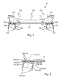
- FIG. 2 shows a sectional view from above through a display device 10 according to the invention according to another preferred embodiment.
- the housing or the support element of the display device 10 was in FIG. 2 not shown.
- the display device 10 off FIG. 2 includes only three pointer elements 13a, 13b and 13c.
- the display device 10 also has more or less than three pointer instruments.
- the middle pointer instrument 13b could also be by an LCD, LED or any other display device.
- the pointer instruments 13a to 13c each have a flat display surface 14a, 14b, 14c.
- the display surface 14b of the central pointer instrument 13b is substantially parallel to an electronic circuit board 20 arranged behind it.
- the display surfaces 14a and 14c of the outer pointer instruments 13a and 13c are arranged at a specific angle at an angle to the printed circuit board 20. Due to the arrangement of the display surfaces shown 14a to 14c also results for the display device 10 FIG. 2 a curved shape, which is particularly easy to see in the plan view.
- each pointer 16a, 16c is driven via a motor shaft 21a, 21c by an electric motor 22a, 22c, which is preferably designed as a stepping motor.
- the pointers 16a, 16c are thus rotationally fixed to the shafts 21a, 21c.
- On the electronic circuit board 20 electrical and / or electronic components and interconnects are formed, which together can form a drive circuit for the display device 10.
- the holding element 23a, 23c according to the invention has first fastening means 24a, 24c for fastening the holding element 23a, 23c on the printed circuit board 20.
- the fastening means 24a, 24c can be formed in any desired manner.
- the fastening means 24a, 24c can be designed as any contact elements, for example as plug-in contact elements or as spring contact elements.
- the fastening means 24a, 24c comprise socket contact elements 26a, 26c formed on the support element 23a, 23c, which engage in contact holes 25a, 25c formed in the circuit board 20.
- contact areas could be formed on the printed circuit board 20 instead of the contacting holes 25a, 25c in which the spring contact elements rest when the holding element 23a, 23c is arranged on the printed circuit board 20 to establish an electrical contact between the holding element 23a, 23c and the printed circuit board 20.
- the female contact elements 26a, 26c of the illustrated embodiment are formed so long that they penetrate into the contacting holes 25a, 25c of the printed circuit board 20 when mounted on the circuit board 20 mounting member 23a, 23c.
- the socket contact elements 26a, 26c are contacted, for example, by means of an arbitrary soldering process, in particular a reflow soldering process, in the contacting holes 25a, 25c with the circuit formed on the printed circuit board 20.
- an arbitrary soldering process in particular a reflow soldering process
- the support member 23a, 23c is enlarged in FIG FIG. 3 shown. It also has second attachment means 27a, 27c for mechanical attachment of the electric motor 22a, 22c to the support member 23a, 23c.
- the second fastening means 27a, 27c can be configured in any desired manner.
- the fastening means 27a, 27c are formed such that they allow a releasable attachment of the electric motor 22a, 22c, in particular by means of a snap or latching connection.
- For fastening the electric motor 22a, 22c to the support element 23a, 23c it is simply inserted from behind into the support element 23a, 23c so that latching elements of the attachment means 27a, 27c are bent apart. Once the electric motor 22a, 22c is fully inserted into the support member 23a, 23c, snap the locking elements back to their original position and secure the electric motor 22a, 22c in the inserted position by means of locking lugs.
- pin contact members 28a, 28c formed on the electric motor 22a, 22c enter the socket contact members 26a, 26c of the support member 23a, 23c and are electrically contacted there.
- the mechanical attachment of the electric motor 22a, 22c in the support member 23a, 23c and the electrical contacting of the electric motor 22a, 22c takes place in one step.
- the support element 23a, 23c according to the invention allows, as shown in FIGS. 2 and 3 Thus, it is possible, even with curved display devices 1, 10 all the electric motors 22a, 22c of the pointer instruments 3a to 3e and 13a to 13c on a single, common, planar, rigid circuit board 20 to attach and contact. This applies not only to the process of mounting the printed circuit board 20, but also to the process of mounting the printed circuit board 20 in the display device 1, 10 and for the duration of the arrangement of the printed circuit board 20 in an operable state in the display device 1, 10. Clearly the attachment and contacting of the electric motors 22a, 22c takes place in a particularly simple and efficient manner.
Landscapes
- Engineering & Computer Science (AREA)
- Chemical & Material Sciences (AREA)
- Combustion & Propulsion (AREA)
- Transportation (AREA)
- Mechanical Engineering (AREA)
- Manufacturing & Machinery (AREA)
- Microelectronics & Electronic Packaging (AREA)
- Instrument Panels (AREA)
Abstract
Description
- Die vorliegende Erfindung betrifft ein Halterungselement zur Befestigung eines Elektromotors auf einer elektronischen Leiterplatte eines elektrischen Zeigerinstruments, wobei der Elektromotor über eine Motorwelle einen Zeiger des Zeigerinstruments antreibt. Ferner betrifft die Erfindung eine Anzeigeeinrichtung eines Kraftfahrzeugs umfassend mindestens ein elektrisches Zeigerinstrument mit mindestens einem durch einen Elektromotor angetriebenen Zeiger, wobei der Elektromotor auf einer elektronischen Leiterplatte befestigt und über diese elektrisch kontaktiert ist und eine Motorwelle aufweist, an der der mindestens eine Zeiger des mindestens einen Zeigerinstruments befestigt ist. Schließlich betrifft die vorliegende Erfindung auch ein Verfahren zur Befestigung eines Elektromotors auf einer elektronischen Leiterplatte eines elektrischen Zeigerinstruments, wobei der Elektromotor über eine Motorwelle einen Zeiger des Zeigerinstruments antreibt.
- Aus dem Stand der Technik sind verschiedene Anzeigeeinrichtungen für Kraftfahrzeuge bekannt, bspw. in Form eines für den Einsatz in einem Kraftfahrzeug vorgesehenen Kombiinstruments zur gleichzeitigen Anzeige verschiedener betriebs- oder verkehrsbezogener Daten des Kraftfahrzeugs bzw. seines Umfelds, wie es bspw. aus der
DE 103 130 131 A1 bekannt ist. Solche Anzeigeeinrichtungen weisen mindestens ein Zeigerinstrument auf, das mindestens einen jeweils durch einen Elektromotor angetriebenen Zeiger umfasst. Das Zeigerinstrument verfügt ferner über eine mit einer Skala versehene Anzeigefläche, wobei vorzugsweise jedem Zeiger eines Zeigerinstruments eine eigene Skala zugeordnet ist. Derartige Zeigerinstrumente werden auch als Analoginstrumente bezeichnet. Die Zeigerinstrumente dienen in Kraftfahrzeugen bspw. zur Anzeige der aktuellen Fahrzeuggeschwindigkeit (Tachometer), der aktuellen Motordrehzahl (Drehzahlmesser), des Tankinhalts, der Batteriespannung, des Ladedrucks eines Turboladers oder Kompressors, der Öltemperatur, des Öldrucks, der Außentemperatur, der Kühlwassertemperatur etc. - Bei Verwendung mehrerer neben- und/oder übereinander angeordneter Zeigerinstrumente in einer Anzeigerichtung sind die einzelnen Zeigerinstrumente bzw. deren Anzeigeflächen häufig um die Position des Fahrers herum jeweils zum Fahrer hin gerichtet angeordnet, sodass sich ein um den Fahrer herum gewölbtes Kombiinstrument ergibt. Aus Gründen einer einfacheren und kostengünstigeren Fertigung wird in der Regel versucht, die elektronische Schaltung einschließlich aller elektrischer und elektronischer Bauteile und der Elektromotoren zum Antrieb der Zeiger sämtlicher Zeigerinstrumente einer Anzeigevorrichtung auf einer einzigen elektronischen Leiterplatte anzuordnen.
- Bei schräg zueinander angeordneten Anzeigeflächen der einzelnen Zeigerinstrumente ist dies im Stand der Technik jedoch nicht möglich. Nach dem Stand der Technik können immer nur diejenigen Elektromotoren auf einer gemeinsamen elektronischen Leiterplatte angeordnet werden, die Zeigerinstrumenten zugeordnet sind, deren Anzeigeflächen auf einer einzigen Ebene oder zumindest auf zueinander parallelen Ebenen angeordnet sind. Elektromotoren, die Zeigerinstrumenten zugeordnet sind, deren Anzeigeflächen schräg zu den Anzeigeflächen der übrigen Zeigerinstrumente angeordnet sind, müssen nach dem Stand der Technik immer auf eigenen, separaten Leiterplatten angeordnet werden. Der Grund hierfür besteht darin, dass versucht wird, Elektromotoren von Zeigerinstrumenten von Anzeigeeinrichtungen immer derart auf den elektronischen Leiterplatten zu befestigen, dass die Motorwellen der Elektromotoren senkrecht zur Flächenerstreckung der Anzeigeflächen verlaufen. Nur so kann auf den Einsatz eines aufwendigen und teuren Gelenks zwischen der Motorwelle und einer senkrecht zur Anzeigefläche angeordneten Zeigerwelle verzichtet werden. Eine entsprechende Befestigung eines Elektromotors auf einer Leiterplatte mittels eines Halterungselements ist bspw. aus der
DE 42 09 823 A1 oder derCN 2725083 Y bekannt. - Es wäre theoretisch denkbar, die Elektromotoren aller Zeigerinstrumente einer Anzeigeeinrichtung auf einer einzigen flexiblen Leiterplatte anzuordnen und diese dann gewölbt in die Anzeigeeinrichtung einzubauen, sodass die Motorwellen sämtlicher Elektromotoren jeweils senkrecht zu den Anzeigeflächen der ihnen zugeordneten Zeigerelemente verlaufen. Dadurch könnten zwar sämtliche Elektromotoren auf einer einzigen Leiterplatte befestigt werden. Die Flexibilität der Leiterplatte würde jedoch zu erheblichen Problemen bei der Bestückung sowie der Handhabung während der Montage in der Anzeigeeinrichtung führen, sodass die Verwendung einer flexiblen Leiterplatte in der Praxis nicht in Betracht gezogen wird.
- Ausgehend von dem beschriebenen Stand der Technik liegt der vorliegenden Erfindung die Aufgabe zu Grunde, bei gewölbten Anzeigeeinrichtungen, bei denen die Anzeigeflächen der einzelnen Zeigerinstrumente zumindest zum Teil schräg zueinander angeordnet sind, sämtliche Elektromotoren zur Betätigung der Zeiger der Zeigerinstrumente auf einer einzigen ebenen starren elektronischen Leiterplatte anzuordnen.
- Zur Lösung dieser Aufgabe wird ausgehend von dem Halterungselement der eingangs genannten Art vorgeschlagen, dass das Halterungselement erste Befestigungsmittel zur Befestigung des Halterungselements auf der Leiterplatte und zweite Befestigungsmittel zur Befestigung des Elektromotors an dem Halterungselement aufweist, wobei die ersten und die zweiten Befestigungsmittel des Halterungselements derart ausgebildet und relativ zueinander angeordnet sind, dass der Elektromotor mit sich schräg zu einer Flächenerstreckung der Leiterplatte erstreckender Motorwelle auf der Leiterplatte befestigt ist.
- Erfindungsgemäß wird also vorgeschlagen, das Halterungselement, mit dem der Elektromotor auf der elektronischen Leiterplatte oder Platine befestigt und elektrisch kontaktiert wird, derart auszugestalten, dass eine schräge Befestigung des Elektromotors auf der Leiterplatte möglich ist. Dabei wird das Halterungselement je nach gewünschtem Winkel der Schrägstellung des Elektromotors relativ zur Leiterplatte ausgestaltet. Durch Befestigen des Halterungselements auf der Leiterplatte in einer bestimmten Drehstellung um eine senkrecht zur Leiterplatte verlaufenden imaginären Drehachse kann die Richtung der Schrägstellung bzw. die Ausrichtung der Motorwelle bezüglich der Leiterplatte festgelegt werden. Gleichartige Halterungselemente können um die imaginäre Drehachse um 180° zueinander gedreht auf der Leiterplatte befestigt werden. Dadurch kann bspw. zum einem ein erster Elektromotor mit nach rechts geneigter Motorwelle und zum anderen ein anderer Elektromotor mit nach links geneigter Motorwelle auf der Leiterplatte befestigt werden. Für unterschiedliche Neigungswinkel des Elektromotors relativ zu der Leiterplatte werden unterschiedliche Halterungselemente vorgesehen.
- Die Anordnung aller Elektromotoren auf einer einzigen, ebenen, starren Leiterplatte gilt nicht nur während der Montage und Bestückung der Leiterplatte, sondern auch dann, wenn die bestückte Leiterplatte in einer betriebsbereiten Position in der Anzeigeeinrichtung eingebaut ist und sich die Anzeigeeinrichtung in einem betriebsbereiten Zustand befindet.
- Die Halterungselemente werden zusammen mit den übrigen elektrischen und elektronischen Bauelementen im Rahmen der Bestückung der Leiterplatte auf dieser angeordnet und bspw. im Rahmen eines Lötprozesses, insbesondere eines Reflow-Lötprozesses, auf dieser befestigt und elektrisch kontaktiert. Anschließend können die Elektromotoren an den Halterungselementen befestigt werden. Dabei werden die Elektromotoren vorzugsweise gleichzeitig mit der Befestigung in den Halterungselementen auch elektrisch kontaktiert. Auf diese Weise können die Elektromotoren in einem einzigen Schritt einerseits an den Halterungselementen mechanisch befestigt und gleichzeitig elektrisch kontaktiert werden.
- Die vorliegende Erfindung erlaubt eine Montage der Elektromotoren schräg zur Flächenerstreckung der elektronischen Leiterplatte. Dadurch ist es erstmals möglich, bei gewölbten Anzeigeeinrichtungen mit mehreren relativ zueinander geneigten Zeigerinstrumenten bzw. zueinander geneigten skalierten Anzeigeflächen der Zeigerinstrumente die den Zeigerinstrumenten zugeordneten Elektromotoren auf einer einzigen gemeinsamen, ebenen, starren Leiterplatte zu befestigen. Das hat erhebliche Vorteile sowohl bei der Bestückung der Leiterplatte als auch bei der Montage der Anzeigeeinrichtung, insbesondere beim Einsetzen der bestückten Leiterplatte mit den darauf befestigten und elektrisch kontaktierten Bauteilen. Mit der vorliegenden Erfindung können gewölbte Anzeigeeinrichtungen eines Kraftfahrzeugs einfach und kostengünstig realisiert werden, wobei gleichzeitig der Herstellungsaufwand deutlich reduziert wird.
- Gemäß einer vorteilhaften Weiterbildung der vorliegenden Erfindung wird vorgeschlagen, dass die ersten Befestigungsmittel derart ausgebildet sind, dass sie eine Befestigung des Halterungselements auf der Leiterplatte mittels eines Lötprozesses, insbesondere eines Reflow-Lötprozesses, erlauben. Zu diesem Zweck weist das Halterungselement vorzugsweise Kontaktelemente auf, die bei auf der Leiterplatte angeordnetem Halterungselement mit entsprechenden Kontaktierungsmitteln der Leiterplatte in Eingriff treten und zumindest im Anschluss an den Lötprozess für eine elektrische Kontaktierung des Halterungselements sorgen. Die Kontaktelemente können bspw. als Steckkontaktelemente oder als Federkontaktelemente ausgebildet sein. Dementsprechend können die Kontaktierungsmittel als in der Leiterplatte ausgebildete Kontaktierungslöcher oder auf der Leiterplatte ausgebildete Kontaktierungsflächen ausgebildet sein. Vorzugsweise werden die Steckkontaktelemente mit Kontaktierungslöchern und die Federkontaktelemente mit Kontaktierungsflächen eingesetzt.
- Vorzugsweise sind die Kontaktierungsmittel der Leiterplatte als Kontaktierungslöcher ausgebildet, welche als Steckkontaktelemente ausgebildete Kontaktelemente des Halterungselements bei auf der Leiterplatte angeordnetem Halterungselement aufnehmen, sodass die Steckkontaktelemente des Halterungselements mittels des Lötprozesses, insbesondere des Reflow-Lötprozesses, in den Kontaktierungslöchern der Leiterplatte kontaktierbar und befestigbar sind. Alternativ können die Kontaktierungsmittel der Leiterplatte auch als Kontaktierungsflächen ausgebildet sein, welche als Federkontaktelemente ausgebildete Kontaktelemente des Halterungselements bei auf der Leiterplatte angeordnetem Halterungselement aufnehmen, sodass die Federkontaktelemente des Halterungselements mittels des Lötprozesses, insbesondere des Reflow-Lötprozesses, auf den Kontaktierungsflächen der Leiterplatte kontaktierbar und befestigbar sind. Dabei nehmen die Kontaktierungsmittel der Leiterplatte bei auf der Leiterplatte angeordnetem Halterungselement die (Flächen- oder Steck-) Kontaktelemente des Halterungselements vorzugsweise automatisch bzw. zwangsläufig auf, so dass es keines zusätzlichen Arbeitsschrittes zur Herstellung des elektrischen Kontakts bedarf.
- Besonders bevorzugt ist dabei, wenn dadurch nicht nur eine elektrische Kontaktierung der Kontaktelemente des Halterungselements erfolgt, sondern gleichzeitig auch das Halterungselement auf der Leiterplatte mechanisch befestigt wird. Damit wird das Halterungselement vorteilhaft in entsprechender Weise wie andere elektronische und elektrische Bauteile und Komponenten ebenfalls im Rahmen eines Reflow-Lötprozesses auf der elektronischen Leiterplatte kontaktiert und befestigt.
- Gemäß einer weiteren bevorzugten Ausführungsform der vorliegenden Erfindung wird vorgeschlagen, dass die zweiten Befestigungsmittel derart ausgebildet sind, dass sie eine lösbare Befestigung des Elektromotors an dem Halterungselement erlauben. Die zweiten Befestigungsmittel sind vorteilhafterweise derart ausgebildet, dass sie eine Befestigung des Elektromotors an dem Halterungselement mittels einer Schnapp- oder Rastverbindung erlauben. Dadurch kann der Elektromotor im Anschluss an den Lötprozess, insbesondere den
- Reflow-Lötprozess, schnell und einfach an dem Halterungselement befestigt werden. Eine zeitsparende und kostengünstige automatisierte Montage der Elektromotoren in großen Stückzahlen ist dadurch möglich.
- Gemäß einer anderen vorteilhaften Weiterbildung der Erfindung wird vorgeschlagen, dass das Halterungselement Kontaktelemente aufweist, die derart ausgebildet und angeordnet sind, dass sie bei an dem Halterungselement befestigtem Elektromotor mit korrespondierenden Kontaktelementen des Elektromotors in Eingriff treten und für eine elektrische Kontaktierung des Elektromotors sorgen. Die Kontaktelemente des Halterungselements sind über die Leiterplatte elektrisch kontaktiert, bspw. mittels des beschriebenen Lötprozesses, insbesondere des Reflow-Lötprozesses. Die Kontaktelemente des Halterungselements sind bspw. als Steck-, Feder- oder Flächenkontaktelemente ausgebildet. Die korrespondierenden Kontaktelemente des Elektromotors sind dementsprechend bspw. als Steck-, Flächen- oder Federkontaktelemente ausgebildet.
- Vorzugsweise sind die Kontaktelemente von Halterungselement und Elektromotor als Steckkontaktelemente ausgebildet, wobei die Steckkontaktelemente des Halterungselements als Buchsenkontaktelemente ausgebildet sind, mit denen die als Stiftkontaktelemente ausgebildeten korrespondierenden Steckkontaktelemente des Elektromotors in Eingriff treten, wenn der Elektromotor in das Halterungselement eingesetzt ist. Demnach wird also der Elektromotor gleichzeitig mit der Befestigung an dem Halterungselement auch elektrisch kontaktiert, indem die Stiftkontaktelemente des Elektromotors in die korrespondierenden Buchsenkontaktelemente des Halterungselements eintreten, wo automatisch ein elektrischer Kontakt zwischen den Buchsenkontaktelementen und den Stiftkontaktelementen hergestellt wird. Dies erlaubt eine besonders einfache und zeiteffiziente Befestigung und Kontaktierung des Elektromotors an dem Halterungselement. Selbstverständlich ist es auch denkbar, dass die Buchsenkontaktelemente an dem Elektromotor und die korrespondierenden Stiftkontaktelemente an dem Halterungselement ausgebildet sind oder dass der Elektromotor nicht lösbar an dem Halterungselement befestigt wird. Ebenso wäre es denkbar, dass das Halterungselement Teil eines Gehäuses des Elektromotors, also ein integraler Bestandteil des Elektromotorgehäuses ist. In diesem Fall müsste entweder der Elektromotor den thermischen Belastungen des Reflow-Lötprozesses standhalten können oder die Elektromotor-Halterungselement-Kombination wird erst im Anschluss an den Reflow-Lötprozess auf der elektronischen Leiterplatte befestigt und elektrisch kontaktiert, bspw. mittels eines beliebig anderen Lötprozesses. Selbst wenn das Halterungselement integraler Bestandteil des Motorgehäuses ist, erlaubt es aufgrund der erfindungsgemäßen Ausgestaltung eine schräge Montage des Elektromotors auf der elektronischen Leiterplatte.
- Gegenstand der vorliegenden Erfindung ist auch eine Anzeigeeinrichtung eines Kraftfahrzeugs der eingangs genannten Art, wobei der Elektromotor mittels eines Halterungselements derart auf der elektronischen Leiterplatte befestigt ist, dass sich die Motorwelle schräg zu einer Flächenerstreckung der Leiterplatte erstreckt. Vorzugsweise ist das Halterungselement als separates Bauteil getrennt von einem Gehäuse des Elektromotors ausgebildet. Ganz besonders vorteilhaft ist eine Anzeigeeinrichtung, bei der der Elektromotor mittels eines erfindungsgemäßen Halterungselements auf der Leiterplatte befestigt und ggf. elektrisch kontaktiert ist.
- Schließlich betrifft die vorliegende Erfindung auch ein Verfahren zur Befestigung eines Elektromotors auf einer elektronischen Leiterplatte der eingangs genannten Art, wobei zunächst ein Halterungselement über erste Befestigungsmittel des Halterungselements auf der Leiterplatte befestigt wird und anschließend der Elektromotor über zweite Befestigungsmittel des Halterungselements an dem Halterungselement befestigt wird, wobei die ersten und zweiten Befestigungsmittel des Halterungselements derart ausgebildet und relativ zueinander angeordnet sind, dass der Elektromotor mit sich schräg zu einer Flächenerstreckung der Leiterplatte erstreckender Motorwelle auf der Leiterplatte befestigt wird.
- Weiter Merkmale und Vorteile der vorliegenden Erfindung werden nachfolgend unter Bezugnahme auf die Figuren näher erläutert. Es wird darauf hingewiesen, dass die vorliegenden Erfindung die angegebenen Merkmale und Vorteile nicht nur in der beschriebenen Kombination, sondern auch in Alleinstellung oder einer beliebig anderen Kombination aufweisen kann. Dabei zeigen:
- Figur 1
- eine perspektivische Ansicht einer erfindungsgemäßen Einrichtung gemäß einem ersten bevorzugten Ausführungsbeispiel;
- Figur 2
- eine Schnittansicht von oben auf eine erfindungsgemäße Anzeigeeinrichtung gemäß einem weiteren bevorzugten Ausführungsbeispiel; und
- Figur 3
- ein erfindungsgemäßes Halterungselement gemäß einer bevorzugten Ausführungsform in vergrößerter Darstellung.
- In
Figur 1 ist eine erfindungsgemäße Anzeigeeinrichtung in ihrer Gesamtheit mit dem Bezugszeichen 1 bezeichnet. Die Anzeigeeinrichtung 1 wird auch als Kombiinstrument bezeichnet. Sie weist ein Gehäuse oder Tragelement 2 auf, in bzw. an dem mehrere Zeigerinstrumente 3 befestigt sind. Die inFigur 1 beispielhaft gezeigte Anzeigeeinrichtung 1 umfasst fünf nebeneinander angeordnete Zeigerinstrumente 3a bis 3e. Selbstverständlich kann die erfindungsgemäße Anzeigeeinrichtung 1 auch mehr oder weniger als die dargestellten fünf Zeigerinstrumente 3a bis 3e aufweisen. - Ferner ist es denkbar, dass die Zeigerinstrumente 3a bis 3e nicht in der dargestellten Weise, sondern auf andere Weise nebeneinander und/oder übereinander und/oder versetzt zueinander in der Anzeigeeinrichtung 1 angeordnet sind. Ferner ist es denkbar, dass eines oder mehrere der Zeigerinstrumente 3a bis 3e durch ein digitales multifunktionales Instrument, bspw. in Form einer LCD- oder LED-Anzeige (sogenanntes Display), ersetzt ist.
- Bei dem in
Figur 1 gezeigten Ausführungsbeispiel der Anzeigeeinrichtung 1 weist das linke Zeigerinstrument 3a eine Anzeigefläche 4a auf, auf der links eine erste Skala 5a' bspw. für den Tankinhalt und rechts (nicht sichtbar) eine zweite Skala 5a" bspw. für die Batteriespannung angeordnet ist. Der ersten Skala 5a' ist ein erster Zeiger 6a' und der zweiten Skala 5a" ein zweiter Zeiger 6a" zugeordnet. - In entsprechender Weise verfügt das Zeigerinstrument 3b über eine ebene Anzeigefläche 4b, auf der links eine erste Skala 5b' bspw. für die Kühlwassertemperatur und rechts eine zweite Skala 5b" bspw. für den Öldruck aufgebracht ist. Der ersten Skala 5b' ist ein erster Zeiger 6b' und der zweiten Skala 5b" ein zweiter Zeiger 6b" zugeordnet.
- In entsprechender Weise weist das Zeigerinstrument 3c eine ebene Anzeigefläche 4c auf, die mit einer Skala 5c bspw. für die aktuelle Motordrehzahl versehen ist. Der Skala 5c ist ein Zeiger 6c zugeordnet. Ferner ist auf der Anzeigefläche 4c eine LCD-, LED- oder beliebig andere Anzeige angeordnet, auf der bspw. die aktuelle Fahrzeuggeschwindigkeit in digitaler Form angezeigt werden kann.
- Das Zeigerinstrument 3d verfügt ebenfalls über eine ebene Anzeigefläche 4d, auf der eine Skala 5d bspw. für die aktuelle Fahrzeuggeschwindigkeit angeordnet ist. Der Skala 5d ist ein Zeiger 6d zugeordnet. Ferner ist auf der Anzeigefläche 4d eine mechanische oder elektronische Anzeige 7d vorgesehen, um die zurückgelegte Fahrtstrecke anzuzeigen.
- Schließlich weist das rechte Zeigerinstrument 3e eine ebene Anzeigefläche 4e auf, auf der eine Skala 5e bspw. für die aktuelle Uhrzeit ausgebildet ist. Der Skala 5e sind zwei Zeiger 6e' und 6e" zugeordnet, die zur Anzeige der aktuellen Stunden und Minuten vorgesehen sind.
- Auf sämtlichen Anzeigefläche 4a bis 4e können beliebig ausgebildete Kontrollleuchtelemente, bspw. zur Anzeige eines eingeschalteten Fahrtlichtes, eines eingeschalteten Fernlichtes, eines aktivierten Blinklichts oder einer beliebigen Notfallsituation des Kraftfahrzeugs und/oder des Motors, ausgebildet sein, die in
Figur 1 jedoch nicht explizit gezeigt sind. - Jeder einzelne der Zeiger 6a', 6a", 6b', 6b", 6c, 6d, 6e', 6e" wird durch einen eigenen separaten Elektromotor, der vorzugsweise als ein Schrittmotor ausgebildet ist, angetrieben bzw. betätigt. In
Figur 1 ist gut zu erkennen, dass die Anzeigeeinrichtung 1 eine um den Fahrer gewölbte Form aufweist, d.h. die verschiedenen Zeigerinstrumente 3a bis 3e bzw. die Anzeigeflächen 4a bis 4e sind zum Betrachter hin gerichtet, sodass zumindest die äußeren Zeigerinstrumente 3a und 3e schräg angeordnet sind. Bezogen auf eine durch die Anzeigefläche 4c des mittleren Zeigerinstruments 3c definierte imaginäre Ebene ist also das linke Zeigerinstrument 3a derart angeordnet, dass die Anzeigefläche 4a bezüglich der durch die Anzeigefläche 4c definierter Ebene nach rechts geneigt ist. In entsprechender Weise ist bei dem rechten Zeigerinstrument 3e die Anzeigefläche 4e bezogen auf die durch die Anzeigefläche 4c definierte Ebene nach links geneigt angeordnet. Bezogen auf die durch die Anzeigefläche 4c definierte Ebene kann auch für die Anzeigeflächen 4b und 4d der Zeigerinstrumente 3b und 3d eine Schrägstellung vorgesehen sein. Durch die Schrägstellung der einzelnen Zeigerinstrumente 3a, 3b, 3d und/oder 3e ergibt sich die gewölbte Form der Anzeigeeinrichtung 1, die durch einen bogenförmigen unteren Rand 8 des Gehäuses 2 veranschaulicht ist. - Bei derart gewölbten Anzeigeeinrichtungen 1 stellt die Befestigung der Elektromotoren zum Antrieb bzw. zur Betätigung der Zeiger 6a' bis 6e" eine Herausforderung dar. Einerseits ist eine Befestigung sämtlicher Elektromotoren auf einer einzigen gemeinsamen elektronischen Leiterplatte wünschenswert. Andererseits müssen die Elektromotoren derart angeordnet werden, dass ihre Motorwellen jeweils senkrecht zur Flächenerstreckung der Anzeigeflächen 4a bis 4e der den Motoren jeweils zugeordneten Zeigerinstrumente 3a bis 3e verlaufen. Diesbezüglich bietet die vorliegenden Erfindung einen besonders vorteilhaften Lösungsansatz, der nachfolgend unter Bezugnahme auf die
Figur 2 näher erläutert wird. -
Figur 2 zeigt eine Schnittansicht von oben durch eine erfindungsgemäße Anzeigeeinrichtung 10 gemäß einer anderen bevorzugten Ausführungsform. Das Gehäuse oder das Tragelement der Anzeigeeinrichtung 10 wurde inFigur 2 nicht eingezeichnet. Die Anzeigeeinrichtung 10 ausFigur 2 umfasst lediglich drei Zeigerelemente 13a, 13b und 13c. - Selbstverständlich ist es auch denkbar, dass die Anzeigeeinrichtung 10 auch mehr oder weniger als drei Zeigerinstrumente aufweist. Bspw. das mittlere Zeigerinstrument 13b könnte auch durch eine LCD-, LED- oder beliebig andere Anzeigeeinrichtung sein.
- Die Zeigerinstrumente 13a bis 13c weisen jeweils eine ebene Anzeigefläche 14a, 14b, 14c auf. Dabei verläuft die Anzeigefläche 14b des mittleren Zeigerinstruments 13b im Wesentlichen parallel zu einer dahinter angeordneten elektronischen Leiterplatte 20. Die Anzeigeflächen 14a und 14c der äußeren Zeigerinstrumente 13a und 13c sind dagegen in einem bestimmten Winkel schräg zu der Leiterplatte 20 angeordnet. Durch die gezeigte Anordnung der Anzeigeflächen 14a bis 14c ergibt sich auch für die Anzeigeeinrichtung 10 aus
Figur 2 eine gewölbte Form, die in der Draufsicht besonders gut zu erkennen ist. - Auf den Anzeigeflächen 14a bis 14c sind eine oder mehrere Skalen aufgebracht, die in
Figur 2 nicht eingezeichnet sind. Den Skalen ist jeweils mindestens ein Zeiger 16a und 16c zugeordnet, wobei der der Skala des mittleren Zeigerinstruments 13b zugeordnete Zeiger nicht eingezeichnet ist. Jeder Zeiger 16a, 16c wird über eine Motorwelle 21a, 21c durch einen Elektromotor 22a, 22c angetrieben, der vorzugsweise als ein Schrittmotor ausgebildet ist. Die Zeiger 16a, 16c sind also drehfest an den Wellen 21a, 21c befestigt. Auf der elektronischen Leiterplatte 20 sind elektrische und/oder elektronische Bauelemente sowie Leiterbahnen ausgebildet, die zusammen eine Ansteuerschaltung für die Anzeigeeinrichtung 10 bilden können. - Aufgrund der Schrägstellung der Anzeigeflächen 14a, 14c der äußeren Zeigerinstrumente 13a, 13c ist es vorteilhaft, die Elektromotoren 22a, 22c schräg auf der Leiterplatte 20 zu befestigen. Dies geschieht mittels eines erfindungsgemäßen Halterungselements 23a, 23c. Das erfindungsgemäße Halterungselement 23a, 23c weist erste Befestigungsmittel 24a, 24c zur Befestigung des Halterungselements 23a, 23c auf der Leiterplatte 20 auf. Die Befestigungsmittel 24a, 24c können in beliebiger Weise ausgebildet sein. Die Befestigungsmittel 24a, 24c können als beliebige Kontaktelemente, bspw. als Steckkontaktelemente oder als Federkontaktelemente ausgebildet sein. In dem dargestellten Ausführungsbeispiel umfassen die Befestigungsmittel 24a, 24c an dem Halterungselement 23a, 23c ausgebildete Buchsenkontaktelemente 26a, 26c, die in Kontaktierungslöcher 25a, 25c eingreifen, die in der Leiterplatte 20 ausgebildet sind. Insbesondere bei als Federkontaktelemente ausgebildeten Befestigungsmitteln 24a, 24c könnten statt der Kontaktierungslöcher 25a, 25c auf der Leiterplatte 20 Kontaktierungsflächen ausgebildet sein, auf denen die Federkontaktelemente bei auf der Leiterplatte 20 angeordnetem Halterungselement 23a, 23c zur Herstellung eines elektrischen Kontakts zwischen dem Halterungselement 23a, 23c und der Leiterplatte 20 aufliegen.
- Die Buchsenkontaktelemente 26a, 26c des dargestellten Ausführungsbeispiels sind so lang ausgebildet, dass sie bei auf die Leiterplatte 20 aufgesetztem Halterungselement 23a, 23c in die Kontaktierungslöcher 25a, 25c der Leiterplatte 20 eindringen. Die Buchsenkontaktelemente 26a, 26c werden bspw. mittels eines beliebigen Lötprozesses, insbesondere eines Reflow-Lötprozesses, in den Kontaktierungslöchern 25a, 25c mit der auf der Leiterplatte 20 ausgebildeten Schaltung kontaktiert. Damit werden nicht nur die Buchsenkontaktelemente 26a, 26c des Halterungselements 23a, 23c elektrisch kontaktiert, sondern wird auch das Halterungselement 23a, 23c als solches auf der Leiterplatte 20 mechanisch befestigt.
- Das Halterungselement 23a, 23c ist vergrößert in
Figur 3 gezeigt. Es verfügt ferner über zweite Befestigungsmittel 27a, 27c zur mechanischen Befestigung des Elektromotors 22a, 22c an dem Halterungselement 23a, 23c. Die zweiten Befestigungsmittel 27a, 27c können in beliebiger Weise ausgestaltet sein. In dem dargestellten Ausführungsbeispiel sind die Befestigungsmittel 27a, 27c derart ausgebildet, dass sie eine lösbare Befestigung des Elektromotors 22a, 22c, insbesondere mittels einer Schnapp- oder Rastverbindung, erlauben. Zur Befestigung des Elektromotors 22a, 22c an dem Halterungselement 23a, 23c wird dieser einfach von hinten in das Halterungselement 23a, 23c eingesetzt, sodass Rastelemente der Befestigungsmittel 27a, 27c auseinander gebogen werden. Sobald der Elektromotor 22a, 22c vollständig in das Halterungselement 23a, 23c eingesetzt ist, schnappen die Rastelemente wieder in ihre ursprüngliche Position zurück und sichern den Elektromotor 22a, 22c in der eingesetzten Position mittels Rastnasen. - Gleichzeitig mit dem Einsetzen des Elektromotors 22a, 22c in das Halterungselement 23a, 23c treten an dem Elektromotor 22a, 22c ausgebildete Stiftkontaktelemente 28a, 28c in die Buchsenkontaktelemente 26a, 26c des Halterungselements 23a, 23c ein und werden dort elektrisch kontaktiert. Somit erfolgt die mechanische Befestigung des Elektromotors 22a, 22c in dem Halterungselement 23a, 23c sowie die elektrische Kontaktierung des Elektromotors 22a, 22c in einem Schritt. Es ist auch denkbar, dass die Kontaktierung der Stiftkontaktelemente 28a, 28c des Elektromotors 22a, 22c in den Buchsenkontaktelementen 26a, 26c derart erfolgt, dass der Elektromotor 22a, 22c dadurch auch mechanisch in dem Halterungselement 23a, 23c gehalten wird, so dass unter Umständen sogar auf die separaten zweiten Befestigungsmittel 27a, 27c verzichtet werden könnte bzw. die Buchsenkontaktelemente 26a, 26c für die Stiftkontaktelemente 28a, 28c als zweite Befestigungsmittel dienen.
- Das erfindungsgemäße Halterungselement 23a, 23c ermöglicht, wie anhand der
Figuren 2 und 3 ersichtlich, eine Montage und Befestigung des Elektromotors 22a, 22c schräg zu einer ebenen, starren Leiterplatte 20. Somit ist es möglich, selbst bei gewölbten Anzeigeeinrichtungen 1, 10 sämtliche Elektromotoren 22a, 22c der Zeigerinstrumente 3a bis 3e sowie 13a bis 13c auf einer einzigen, gemeinsamen, ebenen, starren Leiterplatte 20 zu befestigen und zu kontaktieren. Dies gilt nicht nur für den Prozess der Bestückung der Leiterplatte 20, sondern auch für den Prozess der Montage der Leiterplatte 20 in der Anzeigeeinrichtung 1, 10 und für die Dauer der Anordnung der Leiterplatte 20 in einem betriebsfähigen Zustand in der Anzeigeeinrichtung 1, 10. Dabei erfolgt die Befestigung und Kontaktierung der Elektromotoren 22a, 22c auf besonders einfache und effiziente Weise.
Claims (12)
- Halterungselement (23a, 23c) zur Befestigung eines Elektromotors (22a, 22c) auf einer elektronischen Leiterplatte (20) eines elektrischen Zeigerinstruments (3a, 3b, 3c, 3d, 3e, 13a, 13b, 13c), wobei der Elektromotor (22a, 22c) über eine Motorwelle (21a, 21c) einen Zeiger (6a', 6a", 6b', 6b", 6c, 6d, 6e', 6e", 16a, 16c) des Zeigerinstruments (3a, 3b, 3c, 3d, 3e, 13a, 13b, 13c) antreibt, dadurch gekennzeichnet, dass das Halterungselement (23a, 23c) erste Befestigungsmittel (24a, 24c) zur Befestigung des Halterungselements (23a, 23c) auf der Leiterplatte (20) und zweite Befestigungsmittel (27a, 27c) zur Befestigung des Elektromotors (22a, 22c) an dem Halterungselement (23a, 23c) aufweist, wobei die ersten und zweiten Befestigungsmittel (24a, 24c; 27a, 27c) des Halterungselements (23a, 23c) derart ausgebildet und relativ zueinander angeordnet sind, dass der Elektromotor (22a, 22c) mit sich schräg zu einer Flächenerstreckung der Leiterplatte (20) erstreckender Motorwelle (21a, 21c) auf der Leiterplatte (20) befestigt ist.
- Halterungselement (23a, 23c) nach Anspruch 1, dadurch gekennzeichnet, dass die ersten Befestigungsmittel (24a, 24c) derart ausgebildet sind, dass sie eine Befestigung des Halterungselements (23a, 23c) auf der Leiterplatte (20) mittels eines Lötprozesses, insbesondere eines Reflow-Lötprozesses, erlauben.
- Halterungselement (23a, 23c) nach Anspruch 1 oder 2,
dadurch gekennzeichnet, dass die zweiten Befestigungsmittel (27a, 27c) derart ausgebildet sind, dass sie eine lösbare Befestigung des Elektromotors (22a, 22c) an dem Halterungselement (23a, 23c) erlauben. - Halterungselement (23a, 23c) nach Anspruch 3, dadurch gekennzeichnet, dass die zweiten Befestigungsmittel (27a, 27c) derart ausgebildet sind, dass sie eine Befestigung des Elektromotors (22a, 22c) an dem Halterungselement (23a, 23c) mittels einer Schnapp- oder Rastverbindung erlauben.
- Halterungselement (23a, 23c) nach einem der Ansprüche 1 bis 4, dadurch gekennzeichnet, dass das Halterungselement (23a, 23c) Steck- oder Federkontaktelemente (26a, 26c) aufweist, die derart ausgebildet und angeordnet sind, dass sie bei an dem Halterungselement (23a, 23c) befestigtem Elektromotor (22a, 22c) mit korrespondierenden Steck- oder Federkontaktelementen (28a, 28c) des Elektromotors (22a, 22c) in Eingriff treten und für eine elektrische Kontaktierung des Elektromotors (22a, 22c) sorgen.
- Halterungselement (23a, 23c) nach Anspruch 5, dadurch gekennzeichnet, dass die Steckkontaktelemente (26a, 26c) des Halterungselements (23a, 23c) Buchsenkontaktelemente sind, mit denen die als Stiftkontaktelemente ausgebildeten korrespondierenden Steckkontaktelemente (28a, 28c) des Elektromotors (22a, 22c) in Eingriff treten, wenn der Elektromotor (22a, 22c) an dem Halterungselement (23a, 23c) befestigt ist.
- Halterungselement (23a, 23c) nach Anspruch 5 oder 6,
dadurch gekennzeichnet, dass die Steck- oder Federkontaktelemente (26a, 26c) des Halterungselements (23a, 23c) bei auf der Leiterplatte (20) befestigtem Halterungselement (23a, 23c) mit entsprechenden Kontaktierungsmitteln (25a, 25c) auf der Leiterplatte (20) in Eingriff treten und für eine elektrische Kontaktierung der Steck- oder Federkontaktelemente (26a, 26c) des Halterungselements (23a, 23c) sorgen. - Halterungselement (23a, 23c) nach Anspruch 7, dadurch gekennzeichnet, dass die Kontaktierungsmittel (25a, 25c) der Leiterplatte (20) als Kontaktierungslöcher oder Kontaktierungsflächen ausgebildet sind, welche die Steck- oder Federkontaktelemente (26a, 26c) des Halterungselements (23a, 23c) bei auf der Leiterplatte (20) angeordnetem Halterungselement (23a, 23c) aufnehmen, so dass die Steck- oder Federkontaktelemente (26a, 26c) des Halterungselements (23a, 23c) mittels eines Lötprozesses, insbesondere eines Reflow-Lötprozesses, in den Kontaktierungslöchern (25a, 25c) oder auf den Kontaktierungsflächen der Leiterplatte (20) kontaktierbar und befestigbar sind.
- Anzeigeeinrichtung (1; 10) eines Kraftfahrzeugs umfassend mindestens ein elektrisches Zeigerinstrument (3a, 3b, 3c, 3d, 3e, 13a, 13b, 13c) mit mindestens einem durch einen Elektromotor (22a, 22c) angetriebenen Zeiger (6a', 6a", 6b', 6b", 6c, 6d, 6e', 6e", 16a, 16c), wobei der Elektromotor (22a, 22c) auf einer elektronischen Leiterplatte (20) befestigt und über diese elektrisch kontaktiert ist und eine Motorwelle (21a, 21c) aufweist, an der der mindestens eine Zeiger (6a', 6a", 6b', 6b", 6c, 6d, 6e', 6e", 16a, 16c) des mindestens einen Zeigerinstruments (3a, 3b, 3c, 3d, 3e, 13a, 13b, 13c) befestigt ist, dadurch gekennzeichnet, dass der Elektromotor mittels eines Halterungselements (23a, 23c) derart auf der elektronischen Leiterplatte (20) befestigt ist, dass sich die Motorwelle (21a, 21c) schräg zu einer Flächenerstreckung der Leiterplatte (20) erstreckt.
- Anzeigeeinrichtung nach Anspruch 9, dadurch gekennzeichnet, dass das Halterungselement (23a, 23c) separat von einem Gehäuse des Elektromotors (22a, 22c) ausgebildet ist
- Anzeigeeinrichtung nach Anspruch 9 oder 10, dadurch gekennzeichnet, dass das Halterungselement (23a, 23c) nach einem der Ansprüche 2 bis 8 ausgebildet ist.
- Verfahren zur Befestigung eines Elektromotors (22a, 22c) auf einer elektronischen Leiterplatte (20) eines elektrischen Zeigerinstruments (3a, 3b, 3c, 3d, 3e, 13a, 13b, 13c), wobei der Elektromotor (22a, 22c) über eine Motorwelle (21a, 21c) einen Zeiger (6a', 6a", 6b', 6b", 6c, 6d, 6e', 6e", 16a, 16c) des Zeigerinstruments (3a, 3b, 3c, 3d, 3e, 13a, 13b, 13c) antreibt, dadurch gekennzeichnet, dass zunächst ein Halterungselement (23a, 23c) über erste Befestigungsmittel (24a, 24c) des Halterungselements (23a, 23c) auf der Leiterplatte (20) befestigt wird und anschließend der Elektromotor (22a, 22c) über zweite Befestigungsmittel (27a, 27c) des Halterungselements an dem Halterungselement (23a, 23c) befestigt wird, wobei die ersten und zweiten Befestigungsmittel (24a, 24c; 27a, 27c) des Halterungselements (23a, 23c) derart ausgebildet und relativ zueinander angeordnet sind, dass der Elektromotor (22a, 22c) mit sich schräg zu einer Flächenerstreckung der Leiterplatte (20) erstreckender Motorwelle (21a, 21c) auf der Leiterplatte (20) befestigt wird.
Applications Claiming Priority (1)
| Application Number | Priority Date | Filing Date | Title |
|---|---|---|---|
| DE102011082272A DE102011082272A1 (de) | 2011-09-07 | 2011-09-07 | Halterungselement zur Befestigung eines Elektromotors auf einer elektronischen Leiterplatte, Anzeigeeinrichtung eines Kraftfahrzeugs umfassend ein elektrisches Zeigerinstrument mit einem mittels eines solchen Halterungselements auf einer elektronischen Leiterplatte befestigten Elektromotors sowie Verfahren zur Befestigung eines Elektromotors auf einer elektronischen Leiterplatte mittels eines solchen Halterungselements |
Publications (3)
| Publication Number | Publication Date |
|---|---|
| EP2567853A2 true EP2567853A2 (de) | 2013-03-13 |
| EP2567853A3 EP2567853A3 (de) | 2014-07-02 |
| EP2567853B1 EP2567853B1 (de) | 2018-02-21 |
Family
ID=46384150
Family Applications (1)
| Application Number | Title | Priority Date | Filing Date |
|---|---|---|---|
| EP12171626.0A Not-in-force EP2567853B1 (de) | 2011-09-07 | 2012-06-12 | Halterungselement zur Befestigung eines Elektromotors auf einer elektronischen Leiterplatte, Anzeigeeinrichtung eines Kraftfahrzeugs umfassend ein elektrisches Zeigerinstrument mit einem mittels eines solchen Halterungselements auf einer elektronischen Leiterplatte befestigten Elektromotors sowie Verfahren zur Befestigung eines Elektromotors auf einer elektronischen Leiterplatte mittels eines solchen Halterungselements |
Country Status (2)
| Country | Link |
|---|---|
| EP (1) | EP2567853B1 (de) |
| DE (1) | DE102011082272A1 (de) |
Families Citing this family (1)
| Publication number | Priority date | Publication date | Assignee | Title |
|---|---|---|---|---|
| DE102019117034A1 (de) | 2019-06-25 | 2020-12-31 | Magneti Marelli GmbH | Kombiinstrument eines Kraftfahrzeugs |
Citations (3)
| Publication number | Priority date | Publication date | Assignee | Title |
|---|---|---|---|---|
| DE4209823A1 (de) | 1992-03-26 | 1993-09-30 | Kienzle Uhrenfabriken Gmbh | Schrittmotor |
| DE10130131A1 (de) | 2000-06-26 | 2002-01-03 | Denso Corp | Dynamischer Halbleitersensor und Verfahren zu dessen Herstellung |
| CN2725083Y (zh) | 2004-07-26 | 2005-09-14 | 伟盈光纤通讯有限公司 | 汽车仪表驱动电机专用连接器 |
Family Cites Families (6)
| Publication number | Priority date | Publication date | Assignee | Title |
|---|---|---|---|---|
| JPH0749973B2 (ja) * | 1989-09-29 | 1995-05-31 | 日本精機株式会社 | 計器装置 |
| DE19529122A1 (de) * | 1995-08-08 | 1997-02-13 | Vdo Schindling | Zeigerinstrument |
| DE19632381A1 (de) * | 1996-08-10 | 1998-02-12 | Mannesmann Vdo Ag | Kombinationsinstrument |
| JP2005037238A (ja) * | 2003-07-14 | 2005-02-10 | Denso Corp | 車両用指針計器 |
| FR2926435B1 (fr) * | 2008-01-10 | 2012-02-03 | Johnson Controls Tech Co | Carte electronique comportant une plaque de circuit imprime et un equipement porte par cette plaque. |
| DE202008014682U1 (de) * | 2008-11-05 | 2009-02-26 | Brose Fahrzeugteile GmbH & Co. Kommanditgesellschaft, Würzburg | Elektrische Bremsanlage |
-
2011
- 2011-09-07 DE DE102011082272A patent/DE102011082272A1/de not_active Ceased
-
2012
- 2012-06-12 EP EP12171626.0A patent/EP2567853B1/de not_active Not-in-force
Patent Citations (3)
| Publication number | Priority date | Publication date | Assignee | Title |
|---|---|---|---|---|
| DE4209823A1 (de) | 1992-03-26 | 1993-09-30 | Kienzle Uhrenfabriken Gmbh | Schrittmotor |
| DE10130131A1 (de) | 2000-06-26 | 2002-01-03 | Denso Corp | Dynamischer Halbleitersensor und Verfahren zu dessen Herstellung |
| CN2725083Y (zh) | 2004-07-26 | 2005-09-14 | 伟盈光纤通讯有限公司 | 汽车仪表驱动电机专用连接器 |
Also Published As
| Publication number | Publication date |
|---|---|
| DE102011082272A1 (de) | 2013-03-07 |
| EP2567853B1 (de) | 2018-02-21 |
| EP2567853A3 (de) | 2014-07-02 |
Similar Documents
| Publication | Publication Date | Title |
|---|---|---|
| DE102007023787B4 (de) | Elektromagnetische Abschirmung für Anzeigen | |
| DE102011054818A1 (de) | Elektronische Schaltung | |
| EP1080977B1 (de) | Kombiinstrument | |
| DE10351462B4 (de) | Fahrzeugleuchte | |
| EP2567853B1 (de) | Halterungselement zur Befestigung eines Elektromotors auf einer elektronischen Leiterplatte, Anzeigeeinrichtung eines Kraftfahrzeugs umfassend ein elektrisches Zeigerinstrument mit einem mittels eines solchen Halterungselements auf einer elektronischen Leiterplatte befestigten Elektromotors sowie Verfahren zur Befestigung eines Elektromotors auf einer elektronischen Leiterplatte mittels eines solchen Halterungselements | |
| DE102010021032A1 (de) | Anzeigevorrichtung für ein Kraftfahrzeug | |
| DE19819393C2 (de) | Kombiinstrument und entpsrechendes Herstellungsverfahren | |
| DE19819821C1 (de) | Kombiinstrument und entsprechendes Herstellungsverfahren | |
| DE102014116486A1 (de) | Flache elektronische Schaltung und entsprechende dreidimensionale elektronische Schaltung | |
| DE10033088A1 (de) | Aufschnappen des Spiegelantriebes | |
| EP0799406A1 (de) | Anzeigeinstrument | |
| DE102010043495B4 (de) | Elektrisches Bauteil zur Oberflächenmontage | |
| DE102017212610A1 (de) | Gehäuse zum Aufnehmen und Verkleiden von elektrischen oder elektronischen Bauteilen eines Kraftfahrzeugs, Kraftfahrzeug mit einem derartigen Gehäuse sowie Verfahren zum Herstellen eines derartigen Gehäuses | |
| EP1084893A2 (de) | Kombiinstrument | |
| EP2479066A2 (de) | Sensoranordnung für ein Kraftfahrzeug, Kraftfahrzeug und Verfahren zum Herstellen einer Sensoranordnung | |
| EP0848583B1 (de) | Anzeigevorrichtung | |
| DE60126101T2 (de) | Sicherungskasten für Fahrzeuge | |
| DE102010047521A1 (de) | Anzeigevorrichtung für einen Kraftwagen | |
| EP2829793B1 (de) | Anbauelement für Leuchte | |
| EP3756927B1 (de) | Rahmen eines kombiinstruments eines kraftfahrzeugs und kombiinstrument mit einem solchen rahmen | |
| EP0755822A2 (de) | Anzeigevorrichtung für Funktionen und Betriebszustände eines Kraftfahrzeuges | |
| DE102006008011A1 (de) | Tragbarer elektronischer Zeitmesser | |
| DE102007031645A1 (de) | Kombinations-Anzeigeinstrument für ein Kraftfahrzeug | |
| EP2392066B1 (de) | Leistungselektronik für schalenantrieb | |
| DE20317850U1 (de) | Kompaktes Display |
Legal Events
| Date | Code | Title | Description |
|---|---|---|---|
| PUAI | Public reference made under article 153(3) epc to a published international application that has entered the european phase |
Free format text: ORIGINAL CODE: 0009012 |
|
| AK | Designated contracting states |
Kind code of ref document: A2 Designated state(s): AL AT BE BG CH CY CZ DE DK EE ES FI FR GB GR HR HU IE IS IT LI LT LU LV MC MK MT NL NO PL PT RO RS SE SI SK SM TR |
|
| AX | Request for extension of the european patent |
Extension state: BA ME |
|
| PUAL | Search report despatched |
Free format text: ORIGINAL CODE: 0009013 |
|
| AK | Designated contracting states |
Kind code of ref document: A3 Designated state(s): AL AT BE BG CH CY CZ DE DK EE ES FI FR GB GR HR HU IE IS IT LI LT LU LV MC MK MT NL NO PL PT RO RS SE SI SK SM TR |
|
| AX | Request for extension of the european patent |
Extension state: BA ME |
|
| RIC1 | Information provided on ipc code assigned before grant |
Ipc: G01D 11/24 20060101ALI20140527BHEP Ipc: H05K 1/18 20060101ALI20140527BHEP Ipc: B60K 37/02 20060101AFI20140527BHEP |
|
| 17P | Request for examination filed |
Effective date: 20140930 |
|
| RBV | Designated contracting states (corrected) |
Designated state(s): AL AT BE BG CH CY CZ DE DK EE ES FI FR GB GR HR HU IE IS IT LI LT LU LV MC MK MT NL NO PL PT RO RS SE SI SK SM TR |
|
| RAP1 | Party data changed (applicant data changed or rights of an application transferred) |
Owner name: MAGNETI MARELLI GMBH |
|
| STAA | Information on the status of an ep patent application or granted ep patent |
Free format text: STATUS: EXAMINATION IS IN PROGRESS |
|
| 17Q | First examination report despatched |
Effective date: 20170403 |
|
| GRAJ | Information related to disapproval of communication of intention to grant by the applicant or resumption of examination proceedings by the epo deleted |
Free format text: ORIGINAL CODE: EPIDOSDIGR1 |
|
| STAA | Information on the status of an ep patent application or granted ep patent |
Free format text: STATUS: GRANT OF PATENT IS INTENDED |
|
| GRAP | Despatch of communication of intention to grant a patent |
Free format text: ORIGINAL CODE: EPIDOSNIGR1 |
|
| INTG | Intention to grant announced |
Effective date: 20171016 |
|
| GRAS | Grant fee paid |
Free format text: ORIGINAL CODE: EPIDOSNIGR3 |
|
| GRAA | (expected) grant |
Free format text: ORIGINAL CODE: 0009210 |
|
| STAA | Information on the status of an ep patent application or granted ep patent |
Free format text: STATUS: THE PATENT HAS BEEN GRANTED |
|
| AK | Designated contracting states |
Kind code of ref document: B1 Designated state(s): AL AT BE BG CH CY CZ DE DK EE ES FI FR GB GR HR HU IE IS IT LI LT LU LV MC MK MT NL NO PL PT RO RS SE SI SK SM TR |
|
| REG | Reference to a national code |
Ref country code: GB Ref legal event code: FG4D Free format text: NOT ENGLISH |
|
| REG | Reference to a national code |
Ref country code: CH Ref legal event code: EP |
|
| REG | Reference to a national code |
Ref country code: DE Ref legal event code: R096 Ref document number: 502012012170 Country of ref document: DE Ref country code: AT Ref legal event code: REF Ref document number: 971327 Country of ref document: AT Kind code of ref document: T Effective date: 20180315 |
|
| REG | Reference to a national code |
Ref country code: IE Ref legal event code: FG4D Free format text: LANGUAGE OF EP DOCUMENT: GERMAN |
|
| REG | Reference to a national code |
Ref country code: DE Ref legal event code: R082 Ref document number: 502012012170 Country of ref document: DE Representative=s name: HERRMANN PATENTANWAELTE, DE |
|
| REG | Reference to a national code |
Ref country code: FR Ref legal event code: PLFP Year of fee payment: 7 |
|
| REG | Reference to a national code |
Ref country code: NL Ref legal event code: MP Effective date: 20180221 |
|
| REG | Reference to a national code |
Ref country code: LT Ref legal event code: MG4D |
|
| PG25 | Lapsed in a contracting state [announced via postgrant information from national office to epo] |
Ref country code: ES Free format text: LAPSE BECAUSE OF FAILURE TO SUBMIT A TRANSLATION OF THE DESCRIPTION OR TO PAY THE FEE WITHIN THE PRESCRIBED TIME-LIMIT Effective date: 20180221 Ref country code: CY Free format text: LAPSE BECAUSE OF FAILURE TO SUBMIT A TRANSLATION OF THE DESCRIPTION OR TO PAY THE FEE WITHIN THE PRESCRIBED TIME-LIMIT Effective date: 20180221 Ref country code: LT Free format text: LAPSE BECAUSE OF FAILURE TO SUBMIT A TRANSLATION OF THE DESCRIPTION OR TO PAY THE FEE WITHIN THE PRESCRIBED TIME-LIMIT Effective date: 20180221 Ref country code: HR Free format text: LAPSE BECAUSE OF FAILURE TO SUBMIT A TRANSLATION OF THE DESCRIPTION OR TO PAY THE FEE WITHIN THE PRESCRIBED TIME-LIMIT Effective date: 20180221 Ref country code: NO Free format text: LAPSE BECAUSE OF FAILURE TO SUBMIT A TRANSLATION OF THE DESCRIPTION OR TO PAY THE FEE WITHIN THE PRESCRIBED TIME-LIMIT Effective date: 20180521 Ref country code: NL Free format text: LAPSE BECAUSE OF FAILURE TO SUBMIT A TRANSLATION OF THE DESCRIPTION OR TO PAY THE FEE WITHIN THE PRESCRIBED TIME-LIMIT Effective date: 20180221 Ref country code: FI Free format text: LAPSE BECAUSE OF FAILURE TO SUBMIT A TRANSLATION OF THE DESCRIPTION OR TO PAY THE FEE WITHIN THE PRESCRIBED TIME-LIMIT Effective date: 20180221 |
|
| PG25 | Lapsed in a contracting state [announced via postgrant information from national office to epo] |
Ref country code: GR Free format text: LAPSE BECAUSE OF FAILURE TO SUBMIT A TRANSLATION OF THE DESCRIPTION OR TO PAY THE FEE WITHIN THE PRESCRIBED TIME-LIMIT Effective date: 20180522 Ref country code: RS Free format text: LAPSE BECAUSE OF FAILURE TO SUBMIT A TRANSLATION OF THE DESCRIPTION OR TO PAY THE FEE WITHIN THE PRESCRIBED TIME-LIMIT Effective date: 20180221 Ref country code: LV Free format text: LAPSE BECAUSE OF FAILURE TO SUBMIT A TRANSLATION OF THE DESCRIPTION OR TO PAY THE FEE WITHIN THE PRESCRIBED TIME-LIMIT Effective date: 20180221 Ref country code: SE Free format text: LAPSE BECAUSE OF FAILURE TO SUBMIT A TRANSLATION OF THE DESCRIPTION OR TO PAY THE FEE WITHIN THE PRESCRIBED TIME-LIMIT Effective date: 20180221 Ref country code: BG Free format text: LAPSE BECAUSE OF FAILURE TO SUBMIT A TRANSLATION OF THE DESCRIPTION OR TO PAY THE FEE WITHIN THE PRESCRIBED TIME-LIMIT Effective date: 20180521 |
|
| PG25 | Lapsed in a contracting state [announced via postgrant information from national office to epo] |
Ref country code: MT Free format text: LAPSE BECAUSE OF FAILURE TO SUBMIT A TRANSLATION OF THE DESCRIPTION OR TO PAY THE FEE WITHIN THE PRESCRIBED TIME-LIMIT Effective date: 20180221 |
|
| PG25 | Lapsed in a contracting state [announced via postgrant information from national office to epo] |
Ref country code: PL Free format text: LAPSE BECAUSE OF FAILURE TO SUBMIT A TRANSLATION OF THE DESCRIPTION OR TO PAY THE FEE WITHIN THE PRESCRIBED TIME-LIMIT Effective date: 20180221 Ref country code: AL Free format text: LAPSE BECAUSE OF FAILURE TO SUBMIT A TRANSLATION OF THE DESCRIPTION OR TO PAY THE FEE WITHIN THE PRESCRIBED TIME-LIMIT Effective date: 20180221 Ref country code: EE Free format text: LAPSE BECAUSE OF FAILURE TO SUBMIT A TRANSLATION OF THE DESCRIPTION OR TO PAY THE FEE WITHIN THE PRESCRIBED TIME-LIMIT Effective date: 20180221 Ref country code: RO Free format text: LAPSE BECAUSE OF FAILURE TO SUBMIT A TRANSLATION OF THE DESCRIPTION OR TO PAY THE FEE WITHIN THE PRESCRIBED TIME-LIMIT Effective date: 20180221 |
|
| REG | Reference to a national code |
Ref country code: DE Ref legal event code: R097 Ref document number: 502012012170 Country of ref document: DE |
|
| PG25 | Lapsed in a contracting state [announced via postgrant information from national office to epo] |
Ref country code: DK Free format text: LAPSE BECAUSE OF FAILURE TO SUBMIT A TRANSLATION OF THE DESCRIPTION OR TO PAY THE FEE WITHIN THE PRESCRIBED TIME-LIMIT Effective date: 20180221 Ref country code: CZ Free format text: LAPSE BECAUSE OF FAILURE TO SUBMIT A TRANSLATION OF THE DESCRIPTION OR TO PAY THE FEE WITHIN THE PRESCRIBED TIME-LIMIT Effective date: 20180221 Ref country code: SK Free format text: LAPSE BECAUSE OF FAILURE TO SUBMIT A TRANSLATION OF THE DESCRIPTION OR TO PAY THE FEE WITHIN THE PRESCRIBED TIME-LIMIT Effective date: 20180221 Ref country code: SM Free format text: LAPSE BECAUSE OF FAILURE TO SUBMIT A TRANSLATION OF THE DESCRIPTION OR TO PAY THE FEE WITHIN THE PRESCRIBED TIME-LIMIT Effective date: 20180221 |
|
| PLBE | No opposition filed within time limit |
Free format text: ORIGINAL CODE: 0009261 |
|
| STAA | Information on the status of an ep patent application or granted ep patent |
Free format text: STATUS: NO OPPOSITION FILED WITHIN TIME LIMIT |
|
| 26N | No opposition filed |
Effective date: 20181122 |
|
| REG | Reference to a national code |
Ref country code: CH Ref legal event code: PL |
|
| GBPC | Gb: european patent ceased through non-payment of renewal fee |
Effective date: 20180612 |
|
| PG25 | Lapsed in a contracting state [announced via postgrant information from national office to epo] |
Ref country code: SI Free format text: LAPSE BECAUSE OF FAILURE TO SUBMIT A TRANSLATION OF THE DESCRIPTION OR TO PAY THE FEE WITHIN THE PRESCRIBED TIME-LIMIT Effective date: 20180221 |
|
| REG | Reference to a national code |
Ref country code: BE Ref legal event code: MM Effective date: 20180630 |
|
| REG | Reference to a national code |
Ref country code: IE Ref legal event code: MM4A |
|
| PG25 | Lapsed in a contracting state [announced via postgrant information from national office to epo] |
Ref country code: LU Free format text: LAPSE BECAUSE OF NON-PAYMENT OF DUE FEES Effective date: 20180612 Ref country code: MC Free format text: LAPSE BECAUSE OF FAILURE TO SUBMIT A TRANSLATION OF THE DESCRIPTION OR TO PAY THE FEE WITHIN THE PRESCRIBED TIME-LIMIT Effective date: 20180221 |
|
| PG25 | Lapsed in a contracting state [announced via postgrant information from national office to epo] |
Ref country code: IE Free format text: LAPSE BECAUSE OF NON-PAYMENT OF DUE FEES Effective date: 20180612 Ref country code: CH Free format text: LAPSE BECAUSE OF NON-PAYMENT OF DUE FEES Effective date: 20180630 Ref country code: GB Free format text: LAPSE BECAUSE OF NON-PAYMENT OF DUE FEES Effective date: 20180612 Ref country code: LI Free format text: LAPSE BECAUSE OF NON-PAYMENT OF DUE FEES Effective date: 20180630 |
|
| PG25 | Lapsed in a contracting state [announced via postgrant information from national office to epo] |
Ref country code: BE Free format text: LAPSE BECAUSE OF NON-PAYMENT OF DUE FEES Effective date: 20180630 |
|
| REG | Reference to a national code |
Ref country code: AT Ref legal event code: MM01 Ref document number: 971327 Country of ref document: AT Kind code of ref document: T Effective date: 20180612 |
|
| PG25 | Lapsed in a contracting state [announced via postgrant information from national office to epo] |
Ref country code: AT Free format text: LAPSE BECAUSE OF NON-PAYMENT OF DUE FEES Effective date: 20180612 |
|
| PG25 | Lapsed in a contracting state [announced via postgrant information from national office to epo] |
Ref country code: TR Free format text: LAPSE BECAUSE OF FAILURE TO SUBMIT A TRANSLATION OF THE DESCRIPTION OR TO PAY THE FEE WITHIN THE PRESCRIBED TIME-LIMIT Effective date: 20180221 |
|
| PG25 | Lapsed in a contracting state [announced via postgrant information from national office to epo] |
Ref country code: PT Free format text: LAPSE BECAUSE OF FAILURE TO SUBMIT A TRANSLATION OF THE DESCRIPTION OR TO PAY THE FEE WITHIN THE PRESCRIBED TIME-LIMIT Effective date: 20180221 Ref country code: HU Free format text: LAPSE BECAUSE OF FAILURE TO SUBMIT A TRANSLATION OF THE DESCRIPTION OR TO PAY THE FEE WITHIN THE PRESCRIBED TIME-LIMIT; INVALID AB INITIO Effective date: 20120612 |
|
| PG25 | Lapsed in a contracting state [announced via postgrant information from national office to epo] |
Ref country code: MK Free format text: LAPSE BECAUSE OF NON-PAYMENT OF DUE FEES Effective date: 20180221 |
|
| PG25 | Lapsed in a contracting state [announced via postgrant information from national office to epo] |
Ref country code: IS Free format text: LAPSE BECAUSE OF FAILURE TO SUBMIT A TRANSLATION OF THE DESCRIPTION OR TO PAY THE FEE WITHIN THE PRESCRIBED TIME-LIMIT Effective date: 20180621 |
|
| PGFP | Annual fee paid to national office [announced via postgrant information from national office to epo] |
Ref country code: IT Payment date: 20200625 Year of fee payment: 9 |
|
| PGFP | Annual fee paid to national office [announced via postgrant information from national office to epo] |
Ref country code: FR Payment date: 20210622 Year of fee payment: 10 Ref country code: DE Payment date: 20210618 Year of fee payment: 10 |
|
| PG25 | Lapsed in a contracting state [announced via postgrant information from national office to epo] |
Ref country code: IT Free format text: LAPSE BECAUSE OF NON-PAYMENT OF DUE FEES Effective date: 20210612 |
|
| REG | Reference to a national code |
Ref country code: DE Ref legal event code: R119 Ref document number: 502012012170 Country of ref document: DE |
|
| PG25 | Lapsed in a contracting state [announced via postgrant information from national office to epo] |
Ref country code: FR Free format text: LAPSE BECAUSE OF NON-PAYMENT OF DUE FEES Effective date: 20220630 |
|
| PG25 | Lapsed in a contracting state [announced via postgrant information from national office to epo] |
Ref country code: DE Free format text: LAPSE BECAUSE OF NON-PAYMENT OF DUE FEES Effective date: 20230103 |