EP2567655A2 - Sensor which is attachable to the body, and monitoring apparatus - Google Patents
Sensor which is attachable to the body, and monitoring apparatus Download PDFInfo
- Publication number
- EP2567655A2 EP2567655A2 EP11777556A EP11777556A EP2567655A2 EP 2567655 A2 EP2567655 A2 EP 2567655A2 EP 11777556 A EP11777556 A EP 11777556A EP 11777556 A EP11777556 A EP 11777556A EP 2567655 A2 EP2567655 A2 EP 2567655A2
- Authority
- EP
- European Patent Office
- Prior art keywords
- sensor
- circuit pattern
- flexible board
- bio signals
- chip
- Prior art date
- Legal status (The legal status is an assumption and is not a legal conclusion. Google has not performed a legal analysis and makes no representation as to the accuracy of the status listed.)
- Withdrawn
Links
Images

Classifications
-
- A—HUMAN NECESSITIES
- A61—MEDICAL OR VETERINARY SCIENCE; HYGIENE
- A61B—DIAGNOSIS; SURGERY; IDENTIFICATION
- A61B5/00—Measuring for diagnostic purposes; Identification of persons
- A61B5/44—Detecting, measuring or recording for evaluating the integumentary system, e.g. skin, hair or nails
- A61B5/441—Skin evaluation, e.g. for skin disorder diagnosis
-
- A—HUMAN NECESSITIES
- A61—MEDICAL OR VETERINARY SCIENCE; HYGIENE
- A61B—DIAGNOSIS; SURGERY; IDENTIFICATION
- A61B5/00—Measuring for diagnostic purposes; Identification of persons
- A61B5/24—Detecting, measuring or recording bioelectric or biomagnetic signals of the body or parts thereof
- A61B5/25—Bioelectric electrodes therefor
- A61B5/263—Bioelectric electrodes therefor characterised by the electrode materials
-
- A—HUMAN NECESSITIES
- A61—MEDICAL OR VETERINARY SCIENCE; HYGIENE
- A61B—DIAGNOSIS; SURGERY; IDENTIFICATION
- A61B5/00—Measuring for diagnostic purposes; Identification of persons
- A61B5/24—Detecting, measuring or recording bioelectric or biomagnetic signals of the body or parts thereof
- A61B5/30—Input circuits therefor
-
- A—HUMAN NECESSITIES
- A61—MEDICAL OR VETERINARY SCIENCE; HYGIENE
- A61B—DIAGNOSIS; SURGERY; IDENTIFICATION
- A61B2562/00—Details of sensors; Constructional details of sensor housings or probes; Accessories for sensors
- A61B2562/14—Coupling media or elements to improve sensor contact with skin or tissue
-
- A—HUMAN NECESSITIES
- A61—MEDICAL OR VETERINARY SCIENCE; HYGIENE
- A61B—DIAGNOSIS; SURGERY; IDENTIFICATION
- A61B2562/00—Details of sensors; Constructional details of sensor housings or probes; Accessories for sensors
- A61B2562/16—Details of sensor housings or probes; Details of structural supports for sensors
- A61B2562/164—Details of sensor housings or probes; Details of structural supports for sensors the sensor is mounted in or on a conformable substrate or carrier
-
- A—HUMAN NECESSITIES
- A61—MEDICAL OR VETERINARY SCIENCE; HYGIENE
- A61B—DIAGNOSIS; SURGERY; IDENTIFICATION
- A61B2562/00—Details of sensors; Constructional details of sensor housings or probes; Accessories for sensors
- A61B2562/16—Details of sensor housings or probes; Details of structural supports for sensors
- A61B2562/166—Details of sensor housings or probes; Details of structural supports for sensors the sensor is mounted on a specially adapted printed circuit board
-
- A—HUMAN NECESSITIES
- A61—MEDICAL OR VETERINARY SCIENCE; HYGIENE
- A61B—DIAGNOSIS; SURGERY; IDENTIFICATION
- A61B5/00—Measuring for diagnostic purposes; Identification of persons
- A61B5/68—Arrangements of detecting, measuring or recording means, e.g. sensors, in relation to patient
- A61B5/6801—Arrangements of detecting, measuring or recording means, e.g. sensors, in relation to patient specially adapted to be attached to or worn on the body surface
- A61B5/683—Means for maintaining contact with the body
- A61B5/6832—Means for maintaining contact with the body using adhesives
- A61B5/6833—Adhesive patches
-
- Y—GENERAL TAGGING OF NEW TECHNOLOGICAL DEVELOPMENTS; GENERAL TAGGING OF CROSS-SECTIONAL TECHNOLOGIES SPANNING OVER SEVERAL SECTIONS OF THE IPC; TECHNICAL SUBJECTS COVERED BY FORMER USPC CROSS-REFERENCE ART COLLECTIONS [XRACs] AND DIGESTS
- Y10—TECHNICAL SUBJECTS COVERED BY FORMER USPC
- Y10T—TECHNICAL SUBJECTS COVERED BY FORMER US CLASSIFICATION
- Y10T29/00—Metal working
- Y10T29/49—Method of mechanical manufacture
- Y10T29/49002—Electrical device making
- Y10T29/49117—Conductor or circuit manufacturing
- Y10T29/49124—On flat or curved insulated base, e.g., printed circuit, etc.
- Y10T29/49155—Manufacturing circuit on or in base
Definitions
- the present invention relates to a sensor attachable to the body and a monitoring apparatus including the sensor.
- a monitoring apparatus configured in an adhesive plaster type or a para-aminosalicylic acid (PAS) type and to be attachable to the body, thereby enabling a patient to live without inconvenience in the state in which the patient wears the monitoring apparatus.
- PAS para-aminosalicylic acid
- a sensor In this monitoring apparatus which is attachable to the body, a sensor can have a variety of sizes.
- a sensor is an adhesive plaster type
- the sensor is formed to have a size of 3 cm by 7 cm.
- the sensor is a PAS type, the sensor is formed to have a size of 10 cm by 10 cm.
- the monitoring apparatus it is not desirable to blindly increase its area because of considering convenience of the user.
- such the high-density circuit will increase the production cost of the apparatus.
- An object of an embodiment is to provide a sensor and a monitoring apparatus using such the sensor which are attachable to the body, wherein the sensor has a maximized area efficiency and give a wearable convenience to the user in the state in which the patient wears the monitoring apparatus.
- a sensor is an attachable sensor for measuring bio signals, including a sensor layer formed to be attachable to the skin and configured to have a plurality of sensor layers configured to measure different types of bio signals stacked thereon, a power source configured to supply power to the sensor layer, and sensing electrodes configured to sense the bio signals from the human body, wherein the plurality of sensor layers receives the respective signals sensed by the sensing electrodes and determines whether the received signals can be measured, and a corresponding sensor layer capable of measuring the sensed signal is activated.
- the sensor preferably includes a flexible board, a circuit pattern installed on the flexible board, a plurality of passive elements connected to the circuit pattern, and a sensor chip connected to the circuit pattern and configured to measure the bio signals.
- the flexible board preferably includes one of paper of pulp material, non-woven fabric, textiles, a patch of knitting, and a film.
- the circuit pattern preferably is formed by forming a conductive paste on the flexible board in a circuit form using one of a silk screen method, a vacuum deposition method, and a sputtering deposition method or formed by cutting metal in a pattern of a circuit form and attaching the cut metal on the flexible board, and the sensor chip is bonded to the circuit pattern through flip-chip bonding, wire bonding, or tab bonding.
- a sensor is an attachable sensor for measuring bio signals, including a sensor layer configured to include a flexible board, a circuit pattern installed on the flexible board, a plurality of passive elements connected to the circuit pattern, and a sensor chip connected to the circuit pattern and configured to measure the bio signals, a power source configured to supply power to the sensor layer, and a sensing electrode configured to sense the bio signals from the human body, wherein a sensor circuit formed of the flexible board and the circuit pattern is plural, and the plurality of sensor circuits is coupled in a stack form.
- the flexible board preferably includes one of paper of pulp material, non-woven fabric, textiles, a patch of knitting, and a film.
- the circuit pattern preferably is formed by forming a conductive paste on the flexible board in a circuit form using one of a silk screen method, a vacuum deposition method, and a sputtering deposition method or formed by cutting metal in a pattern of a circuit form and attaching the cut metal on the flexible board, and the sensor chip is bonded to the circuit pattern through flip-chip bonding, wire bonding, or tab bonding.
- a sensor is an attachable sensor for measuring bio signals, including a sensor layer configured to include a flexible board, a circuit pattern installed on the flexible board, a plurality of passive elements connected to the circuit pattern, and a sensor chip connected to the circuit pattern and configured to measure the bio signals, a power source configured to supply power to the sensor layer, and a sensing electrode configured to sense the bio signals from the human body, wherein a sensor circuit formed of the flexible board and the circuit pattern is plural, and the plurality of sensor circuits is coupled in a stack form, a plurality of the sensor layers is configured so that the sensor layers measure different types of bio signals, respectively, and the plurality of sensor layers is stacked, and the plurality of sensor layers receives the respective signals sensed by the sensing electrodes and determines whether the received signals can be measured, and a corresponding sensor layer capable of measuring the sensed signal is activated.
- the flexible board preferably includes one of paper of pulp material, non-woven fabric, textiles, a patch of knitting, and a film.
- the circuit pattern preferably is formed by forming a conductive paste on the flexible board in a circuit form using one of a silk screen method, a vacuum deposition method, and a sputtering deposition method or formed by cutting metal in a pattern of a circuit form and attaching the cut metal on the flexible board, and the sensor chip preferably is bonded to the circuit pattern through flip-chip bonding, wire bonding, or tab bonding.
- a monitoring apparatus is a monitoring apparatus for monitoring bio signals, including a sensor of an adhesive plaster type formed to be attachable to the skin and configured to include a sensor layer configured to have a plurality of sensor layers for measuring different types of bio signals, respectively, stacked thereon, a power source configured to supply power to the sensor layer, and sensing electrodes configured to sense the bio signals from the human body, and an external terminal configured to receive measured data through the sensor and process the received data, wherein the plurality of sensor layers receives the respective signals sensed by the sensing electrodes and determines whether the received signals can be measured, and a corresponding sensor layer capable of measuring the sensed signal is activated.
- the sensor preferably includes a flexible board, a circuit pattern installed on the flexible board, a plurality of passive elements connected to the circuit pattern, and a sensor chip connected to the circuit pattern and configured to measure the bio signals.
- the flexible board preferably includes one of paper of pulp material, non-woven fabric, textiles, a patch of knitting, and a film.
- the circuit pattern preferably is formed by forming a conductive paste on the flexible board in a circuit form using one of a silk screen method, a vacuum deposition method, and a sputtering deposition method or formed by cutting metal in a pattern of a circuit form and attaching the cut metal on the flexible board, and the sensor chip preferably is bonded to the circuit pattern through flip-chip bonding, wire bonding, or tab bonding.
- the sensor chip preferably transmits the measured data to the external terminal wirelessly.
- the monitoring apparatus preferably further includes an inductor connected to the sensor chip, wherein the inductor is connected to the external terminal using inductive coupling or radio frequency (RF) communication.
- RF radio frequency
- a monitoring apparatus is a monitoring apparatus for monitoring bio signals, including a sensor of an adhesive plaster type configured to include a sensor layer comprising a flexible board, a circuit pattern installed on the flexible board, a plurality of passive elements connected to the circuit pattern, and a sensor chip connected to the circuit pattern and configured to measure the bio signals, a power source configured to supply power to the sensor layer, and a sensing electrode configured to sense the bio signals from the human body, and an external terminal configured to receive measured data through the sensor and process the received data, wherein a sensor circuit formed of the flexible board and the circuit pattern is plural, and the plurality of sensor circuits is coupled in a stack form.
- the flexible board preferably includes one of paper of pulp material, non-woven fabric, textiles, a patch of knitting, and a film.
- the circuit pattern preferably is formed by forming a conductive paste on the flexible board in a circuit form using one of a silk screen method, a vacuum deposition method, and a sputtering deposition method or formed by cutting metal in a pattern of a circuit form and attaching the cut metal on the flexible board, and the sensor chip preferably is bonded to the circuit pattern through flip-chip bonding, wire bonding, or tab bonding.
- the sensor chip preferably transmits the measured data to the external terminal wirelessly.
- the monitoring apparatus preferably further includes an inductor connected to the sensor chip, wherein the inductor is connected to the external terminal using inductive coupling or radio frequency (RF) communication.
- RF radio frequency
- a monitoring apparatus is a monitoring apparatus for monitoring bio signals, including a sensor of an adhesive plaster type configured to include a sensor layer comprising a flexible board, a circuit pattern installed on the flexible board, a plurality of passive elements connected to the circuit pattern, and a sensor chip connected to the circuit pattern and configured to measure the bio signals, a power source configured to supply power to the sensor layer, and a sensing electrode configured to sense the bio signals from the human body, and an external terminal configured to receive measured data through the sensor and process the received data, wherein a sensor circuit formed of the flexible board and the circuit pattern is plural, and the plurality of sensor circuits is coupled in a stack form, a plurality of the sensor layers is configured so that the sensor layers measure different types of bio signals, respectively, and the plurality of sensor layers is stacked, and the plurality of sensor layers receives the respective signals sensed by the sensing electrodes and determines whether the received signals can be measured, and a corresponding sensor layer capable of measuring the sensed signal is activated.
- the flexible board preferably includes one of paper of pulp material, non-woven fabric, textiles, a patch of knitting, and a film.
- the circuit pattern preferably is formed by forming a conductive paste on the flexible board in a circuit form using one of a silk screen method, a vacuum deposition method, and a sputtering deposition method or formed by cutting metal in a pattern of a circuit form and attaching the cut metal on the flexible board, and the sensor chip preferably is bonded to the circuit pattern through flip-chip bonding, wire bonding, or tab bonding.
- the sensor chip preferably transmits the measured data to the external terminal wirelessly.
- the monitoring apparatus preferably further includes an inductor connected to the sensor chip, wherein the inductor is connected to the external terminal using inductive coupling or radio frequency (RF) communication.
- RF radio frequency
- a wearable sensor and a monitoring with a maximized area efficiency there is provided a wearable sensor and a monitoring with a maximized area efficiency.
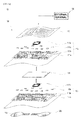
- FIG. 1A is a diagram showing an example of the construction of a monitoring apparatus 10 in accordance with a first embodiment.
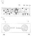
- FIG. 1B is a diagram showing an example of the construction of a first sensor layer 110a in accordance with an embodiment.
- FIG. 1C is a diagram showing the construction of the bottom of a sensor 100 in accordance with an embodiment.
- the monitoring apparatus 10 in accordance with the first embodiment includes a sensor 100 and an external terminal 150.
- the sensor 100 includes a plurality of sensor layers 110a and 110b, a power source 120, and sensing electrodes 130a and 130b.
- Each of the sensor layers 110a and 110b can be fabricated in an adhesive plaster type which can be attached to the skin.
- a plurality of the sensor layers 110a and 110b can be stacked.
- the plurality of sensor layers 110a and 110b can be configured to measure different types of bio signals, respectively.
- a first sensor layer 110a and a second sensor layer 110b two sensor layers 110a and 110b are configured is described.
- the first sensor layer 110a includes a flexible board 111a, a circuit pattern 113a, a plurality of passive elements 115a, and a sensor chip 117a.
- the flexible board 111a can be configured to include one of paper of pulp material, non-woven fabric, textiles, a patch of knitting, and a film.
- one of both faces of the flexible board 111a can be an adhesive surface having an adhesive property.
- the circuit pattern 113a can be formed by forming a conductive paste on the flexible board 111a in a circuit form using one of a silk screen method, a vacuum deposition method, and a sputtering deposition method. Or, the circuit pattern 113a can be formed by cutting metal in a pattern of a circuit form and attaching the cut metal on the flexible board 111a. The circuit pattern 113a is formed on an opposite side to the adhesive surface of the flexible board 111a.
- the passive elements 115a are installed on the circuit pattern 113a and can be electrically connected to the circuit pattern 113a.
- the sensor chip 117a is installed on the circuit pattern 113a and can be electrically connected to the circuit pattern 113a.
- the sensor chip 117a can be connected to the circuit pattern 113a by flip-chip bonding, wire bonding, or tab bonding.
- the sensor chip 117a can be a bare die IC chip.
- the sensor chip 117a can measure bio signals from the human body using the sensing electrodes 130a and 130b.
- the sensor chip 117a can amplify the measured bio signals, perform filtering processing on the amplified signals, and convert them into digital data.
- the sensor chip 117a can perform processing processes, such as compression/encryption, on the converted data, store the processed data, and transmit the stored data to the external terminal 150 wirelessly. Or, the sensor chip 117a can wirelessly transmit the measured raw data to the external terminal 150 without change.
- an inductor 140 (used as a RF antenna) can be additionally configured in the sensor layers 110a and 110b.
- the inductor 140 can be installed at the top of the sensor layers 110a and 110b, and it enables the sensor chip 117a and the external terminal 150 to be wirelessly coupled using inductive coupling circuit or Radio Frequency (RF) communication, functioning as a wireless module. Accordingly, the sensor chip 117a can transmit the measured data to the external terminal 150 through the inductor 140.
- RF Radio Frequency
- the sensor chip 117a can be configured to directly transmit the measured data wirelessly or can be configured to access the external terminal 150 through the inductor 140, but the present invention is not necessarily limited to the above constructions.
- the sensor chip 117a can be configured to transmit the data, stored in the sensor chip 117a, to the external terminal 150 through a wired method.
- the second sensor layer 110b includes a flexible board 111b, a circuit pattern 113b, a plurality of passive elements 115b, and a sensor chip 117b.
- the second sensor layer 110b has a similar construction as the first sensor layer 110a.
- the sensor chip 117a configured in the first sensor layer 110a and the sensor chip 117b configured in the second sensor layer 110b can be configured to measure different bio signals.
- the first sensor layer 110a and/or the second sensor layer 110b can include one or more sensor circuits.
- the sensor circuits mean circuits formed of the flexible boards 111a and 111b and the circuit patterns 113a and 113b.
- the sensor circuit can be stacked under a sensor circuit that is basically configured in the first sensor layer 110a.
- the added sensor circuit can be connected to the sensor circuit that is basically configured in the first sensor layer 110a, and the two stacked sensor circuits can operate as one sensor circuit.
- the two stacked sensor circuits do not need to necessarily come in contact with each other physically and another element layer can be stacked in a middle layer between the two stacked sensor layers. However, the two sensor circuits need to be electrically coupled.
- the construction of the sensor circuits stacked as described above can increase area efficiency because the limited space (or area) of the sensor is utilized to a maximum extent.
- the power source 120 can be installed between the first sensor layer 110a and the second sensor layer 110b, between the sensor circuit and the sensor circuit, or at the top of the sensor layers 110a and 110b.
- the power source 120 can be connected to the sensor chips 117a and 117b, and it can supply power to the sensor layers 110a and 110b.
- the power source 120 can use a flexible battery or work based on wireless power transmission such as RFID.
- FIG. 1C is a diagram showing the construction of the bottom of the sensor in accordance with an embodiment.
- the sensing electrodes 130a and 130b are configured to sense bio signals from the human body and connected to the respective sensor chips 117a and 117b.
- the sensing electrodes 130a and 130b can be installed between the first sensor layer 110a and the second sensor layer 110b or at the bottom of the sensor layers 110a and 110b.
- the bottom of the sensor layers 110a and 110b can be the bottom of the flexible board 111b that is configured in the second sensor layer 110b.
- the sensing electrodes 130a and 130b preferably are installed at the bottom of the sensor layers 110a and 110b in order to reduce a feeling of foreign material for the sensor 100.
- the second sensor layer 110b can be disposed at the bottom of the sensor layer.
- the sensing electrodes 130a and 130b can be installed on the adhesive surface A of the flexible board 111b that is configured in the second sensor layer 110b.
- the external terminal 150 can receive measured data through the sensor 100 and process the measured data.
- the external terminal 150 can perform processing processes, such as decompression/decoding, on the received data, and store the processed data.
- the external terminal 150 can be a portable terminal the user is having so that the external terminal 150 remotely transmits information through a wire or wireless network and receives signals to control the sensor 100.
- the external terminal 150 can be configured to perform communication with the sensor 100 using inductive coupling or RF communication.
- the data communication between the external terminal 150 and the sensor 100 can be performed by a wired manner or by a human body communication technology.
- the sensor chips 117a and 117b can be initialized and connected to the power source 120.
- bio signals from the human body are sensed through the sensing electrodes 130a and 130b, and then the sensed bio signals are inputted to the sensor chips 117a and 117b.
- Each of the sensor chips 117a and 117b measures the received bio signal and determines whether the measured bio signal can be processed. Furthermore, each of the sensor chips 117a and 117b is activated or deactivated according to a result of the determination.
- the first sensor layer 110a can be activated, whereas the second sensor layer 110b can be deactivated. Accordingly, the first sensor layer 110a measures the bio signals from the human body using the sensing electrodes 130a and 130b.
- the second sensor layer 110b can be activated, whereas the first sensor layer 110a can be deactivated. Accordingly, the second sensor layer 110b measures the bio signals from the human body using the sensing electrodes 130a and 130b.
- a sensor layer to be activated can be selected in response to an external command, and when the selected sensor layer is activated, the sensor 100 may operate.
- measured bio signals can be amplified and filtered through corresponding sensor chips and then converted into digital data. Furthermore, the converted data can be subject to processing processes, such as compression/encryption, through the corresponding sensor chips, and then stored, and the stored data can be transmitted to the external terminal 150. Or, the measured raw data can be transmitted to the external terminal 150 without change.
- the inductor 140 is configured in the sensor 100, data stored in a corresponding sensor chip can be transmitted to the external terminal 150 through the inductor 140.
- FIG. 2 is a diagram showing an example of the construction of a monitoring apparatus 20 in accordance with a second embodiment.
- the monitoring apparatus 20 in accordance with the second embodiment includes a sensor 200 and an external terminal 250. Being different the first embodiment, the second embodiment can reduce a surface area of the sensor, by providing the sensor 200 having a plurality of layers 210a and 210b.
- the sensor 200 includes first and second sensor layers 210a and 210b, a power source 220, and sensing electrodes 230a and 230b.
- the first sensor layer 210a can be fabricated in an adhesive plaster type which can be attached to the skin.
- the first sensor layer 210a includes a plurality of passive elements 215, a sensor chip 217, a circuit pattern 213a, and a flexible board 211a.
- the second sensor layer 210a includes a flexible board 211b and a circuit pattern 213b.
- the second sensor layer 210b which does not include the sensor chip 217 can be configured by one array or a plurality of arrays.
- the first and second sensor layers 210a and 210b can be stacked and electrically coupled.
- the plurality of sensor layers can operate as one sensing circuit.
- the stacked construction as described above can increase area efficiency because the limited space (or area) of the sensor is utilized to a maximum extent.
- the flexible boards 211a and 211b can be configured using paper of pulp material, non-woven fabric, textiles, a patch of knitting, and a film.
- any one of both faces of the flexible boards 211a and 211b can be an adhesive surface having an adhesive property in order to be attached to human body for the sensor 200 or between sensor layers.
- the circuit patterns 213a and 213b can be formed by forming a conductive paste on the respective flexible boards 211a and 211b in a circuit form using one of a silk screen method, a vacuum deposition method, and a sputtering deposition method. Or, the circuit patterns 213a and 213b can be formed by cutting metal in a pattern of a circuit form and attaching them to the flexible boards 211a and 211b, respectively.
- the circuit patterns 213a and 213b are formed on an opposite side to the adhesive surface of the flexible boards 211a and 211b.
- the passive elements 215 are installed on the circuit pattern 213a and can be electrically connected to the circuit pattern 213a.
- the sensor chip 217 is installed on the circuit pattern 213a and can be electrically connected to the circuit pattern 213a.
- the sensor chip 217 can be connected to the circuit pattern 213a through flip-chip bonding, wire bonding, or tab bonding.
- the sensor chip 217 can be a bare die IC chip.
- the sensor chip 217 can measure bio signals from the human body using the sensing electrodes 230a and 230b.
- the sensor chip 217 can amplify and filter the measured bio signals and convert the processed data into digital data.
- the sensor chip 217 can perform processing processes, such as compression/encryption, on the converted data, store the processed data, and wirelessly transmit the stored data to the external terminal 250. Or, the sensor chip 217 can transmit the measured raw data to the external terminal 250 wirelessly without change.
- an inductor 240 can be additionally configured in the sensor layer 210.
- the inductor 240 can be installed at the top of the sensor layer 210, and it enables the sensor chip 217 and the external terminal 250 to be wirelessly coupled using inductive coupling or Radio Frequency (RF) communication. Accordingly, the sensor chip 217 can transmit information to the external terminal 250 through the inductor 240.
- RF Radio Frequency
- the sensor chip 217 can be configured to directly transmit the measured data wirelessly or can be configured to access the external terminal 250 through the inductor 240, but the present invention is not necessarily limited to the above constructions.
- the sensor chip 217 can be configured to transmit the data, stored in the sensor chip 217, to the external terminal 250 through a wired method.
- the sensor layer 210a or 210b can be configured by one or more arrays.
- the one or more sensor layers 210 can be configured like the sensor layers 110a and 110b of the first embodiment, and the sensor 200 has the similar operating method as the sensor 100 of the first embodiment.
- each sensor layer can be configured to have a plurality of stacked structures.
- the power source 220 can be installed between the stacked sensor circuits 214a and 214b or at the top of the sensor layer 210.
- the power source 220 can be connected to the sensor chip 217, and it can supply power to the sensor chip 217.
- the power source 220 can be a flexible battery.
- the sensing electrodes 230a and 230b are configured to sense bio signals from the human body and are connected to the sensor chip 217.
- the sensing electrodes 230a and 230b can be installed in the stacked sensor circuits 214a and 214b or at the bottom of the sensor circuits 214a and 214b.
- the bottom of the sensor circuits 214a and 214b can be the bottom of the flexible board 211b that is configured at the lowest layer.
- the sensing electrodes 230a and 230b preferably are installed at the bottom of the sensor layers 210a and 210b in order to reduce a feeling of foreign material for the sensor 200.
- the sensing electrodes 230a and 230b can be installed on the adhesive surface A of the flexible board 211b that is configured at the lowest layer.
- the external terminal 250 can receive measured data from the sensor 200 and process the received data.
- the external terminal 250 can perform processing processes, such as decompression/decoding, on the received data and store the processed data.
- the external terminal 150 can be configured to communicate with the sensor 200 using inductive coupling or RF communication.
- the external terminal 250 can be connected to the sensor 200 in a wired manner and configured to communication with the sensor 200.
- sensors are configured by piling up the sensors in a multi-layer structure. Accordingly, the degree of integration of circuits can be increased because a limited area can be utilized to a maximum extent.
- the attachable sensor having maximized area efficiency and the monitoring apparatus including the sensor can be provided.
- the present invention is used in a sensor attachable to the body and a monitoring apparatus including the sensor.
Landscapes
- Health & Medical Sciences (AREA)
- Life Sciences & Earth Sciences (AREA)
- Medical Informatics (AREA)
- Animal Behavior & Ethology (AREA)
- Pathology (AREA)
- Engineering & Computer Science (AREA)
- Biomedical Technology (AREA)
- Heart & Thoracic Surgery (AREA)
- Physics & Mathematics (AREA)
- Molecular Biology (AREA)
- Surgery (AREA)
- Biophysics (AREA)
- General Health & Medical Sciences (AREA)
- Public Health (AREA)
- Veterinary Medicine (AREA)
- Dermatology (AREA)
- Measuring And Recording Apparatus For Diagnosis (AREA)
- Measurement And Recording Of Electrical Phenomena And Electrical Characteristics Of The Living Body (AREA)
- Measurement Of The Respiration, Hearing Ability, Form, And Blood Characteristics Of Living Organisms (AREA)
Abstract
One embodiment of the present invention relates to a sensor for measuring biosignals. The sensor according to said embodiment comprises: a sensor layer formed by stacking a plurality of sensor layers that are attachable to the skin to measure different types of bio signals; a power for supplying power to the sensor layer; and a sensing electrode for sensing biosignals from the human body. The plurality of sensor layers takes the signals sensed by the sensing electrode as an input, and determines whether or not to measure the inputted signals. Then, the relevant sensor layer that can measure the sensed signal is activated.
Description
- The present invention relates to a sensor attachable to the body and a monitoring apparatus including the sensor.
- Recently, there has been proposed a monitoring apparatus configured in an adhesive plaster type or a para-aminosalicylic acid (PAS) type and to be attachable to the body, thereby enabling a patient to live without inconvenience in the state in which the patient wears the monitoring apparatus.
- In this monitoring apparatus which is attachable to the body, a sensor can have a variety of sizes.
- In general, if a sensor is an adhesive plaster type, the sensor is formed to have a size of 3 cm by 7 cm. If the sensor is a PAS type, the sensor is formed to have a size of 10 cm by 10 cm. In case where the monitoring apparatus is attached to the body, it is not desirable to blindly increase its area because of considering convenience of the user. In order to configure the sensor circuit within this limited area, it should be made by high-density structures. However, such the high-density circuit will increase the production cost of the apparatus.
- An object of an embodiment is to provide a sensor and a monitoring apparatus using such the sensor which are attachable to the body, wherein the sensor has a maximized area efficiency and give a wearable convenience to the user in the state in which the patient wears the monitoring apparatus.
- A sensor according to an embodiment is an attachable sensor for measuring bio signals, including a sensor layer formed to be attachable to the skin and configured to have a plurality of sensor layers configured to measure different types of bio signals stacked thereon, a power source configured to supply power to the sensor layer, and sensing electrodes configured to sense the bio signals from the human body, wherein the plurality of sensor layers receives the respective signals sensed by the sensing electrodes and determines whether the received signals can be measured, and a corresponding sensor layer capable of measuring the sensed signal is activated.
- The sensor preferably includes a flexible board, a circuit pattern installed on the flexible board, a plurality of passive elements connected to the circuit pattern, and a sensor chip connected to the circuit pattern and configured to measure the bio signals.
- The flexible board preferably includes one of paper of pulp material, non-woven fabric, textiles, a patch of knitting, and a film.
- The circuit pattern preferably is formed by forming a conductive paste on the flexible board in a circuit form using one of a silk screen method, a vacuum deposition method, and a sputtering deposition method or formed by cutting metal in a pattern of a circuit form and attaching the cut metal on the flexible board, and the sensor chip is bonded to the circuit pattern through flip-chip bonding, wire bonding, or tab bonding.
- A sensor according to an embodiment is an attachable sensor for measuring bio signals, including a sensor layer configured to include a flexible board, a circuit pattern installed on the flexible board, a plurality of passive elements connected to the circuit pattern, and a sensor chip connected to the circuit pattern and configured to measure the bio signals, a power source configured to supply power to the sensor layer, and a sensing electrode configured to sense the bio signals from the human body, wherein a sensor circuit formed of the flexible board and the circuit pattern is plural, and the plurality of sensor circuits is coupled in a stack form.
- The flexible board preferably includes one of paper of pulp material, non-woven fabric, textiles, a patch of knitting, and a film.
- The circuit pattern preferably is formed by forming a conductive paste on the flexible board in a circuit form using one of a silk screen method, a vacuum deposition method, and a sputtering deposition method or formed by cutting metal in a pattern of a circuit form and attaching the cut metal on the flexible board, and the sensor chip is bonded to the circuit pattern through flip-chip bonding, wire bonding, or tab bonding.
- A sensor according to an embodiment is an attachable sensor for measuring bio signals, including a sensor layer configured to include a flexible board, a circuit pattern installed on the flexible board, a plurality of passive elements connected to the circuit pattern, and a sensor chip connected to the circuit pattern and configured to measure the bio signals, a power source configured to supply power to the sensor layer, and a sensing electrode configured to sense the bio signals from the human body, wherein a sensor circuit formed of the flexible board and the circuit pattern is plural, and the plurality of sensor circuits is coupled in a stack form, a plurality of the sensor layers is configured so that the sensor layers measure different types of bio signals, respectively, and the plurality of sensor layers is stacked, and the plurality of sensor layers receives the respective signals sensed by the sensing electrodes and determines whether the received signals can be measured, and a corresponding sensor layer capable of measuring the sensed signal is activated.
- The flexible board preferably includes one of paper of pulp material, non-woven fabric, textiles, a patch of knitting, and a film.
- The circuit pattern preferably is formed by forming a conductive paste on the flexible board in a circuit form using one of a silk screen method, a vacuum deposition method, and a sputtering deposition method or formed by cutting metal in a pattern of a circuit form and attaching the cut metal on the flexible board, and the sensor chip preferably is bonded to the circuit pattern through flip-chip bonding, wire bonding, or tab bonding.
- A monitoring apparatus according to an embodiment is a monitoring apparatus for monitoring bio signals, including a sensor of an adhesive plaster type formed to be attachable to the skin and configured to include a sensor layer configured to have a plurality of sensor layers for measuring different types of bio signals, respectively, stacked thereon, a power source configured to supply power to the sensor layer, and sensing electrodes configured to sense the bio signals from the human body, and an external terminal configured to receive measured data through the sensor and process the received data, wherein the plurality of sensor layers receives the respective signals sensed by the sensing electrodes and determines whether the received signals can be measured, and a corresponding sensor layer capable of measuring the sensed signal is activated.
- The sensor preferably includes a flexible board, a circuit pattern installed on the flexible board, a plurality of passive elements connected to the circuit pattern, and a sensor chip connected to the circuit pattern and configured to measure the bio signals.
- The flexible board preferably includes one of paper of pulp material, non-woven fabric, textiles, a patch of knitting, and a film.
- The circuit pattern preferably is formed by forming a conductive paste on the flexible board in a circuit form using one of a silk screen method, a vacuum deposition method, and a sputtering deposition method or formed by cutting metal in a pattern of a circuit form and attaching the cut metal on the flexible board, and the sensor chip preferably is bonded to the circuit pattern through flip-chip bonding, wire bonding, or tab bonding.
- The sensor chip preferably transmits the measured data to the external terminal wirelessly.
- The monitoring apparatus preferably further includes an inductor connected to the sensor chip, wherein the inductor is connected to the external terminal using inductive coupling or radio frequency (RF) communication.
- A monitoring apparatus according to an embodiment is a monitoring apparatus for monitoring bio signals, including a sensor of an adhesive plaster type configured to include a sensor layer comprising a flexible board, a circuit pattern installed on the flexible board, a plurality of passive elements connected to the circuit pattern, and a sensor chip connected to the circuit pattern and configured to measure the bio signals, a power source configured to supply power to the sensor layer, and a sensing electrode configured to sense the bio signals from the human body, and an external terminal configured to receive measured data through the sensor and process the received data, wherein a sensor circuit formed of the flexible board and the circuit pattern is plural, and the plurality of sensor circuits is coupled in a stack form.
- The flexible board preferably includes one of paper of pulp material, non-woven fabric, textiles, a patch of knitting, and a film.
- The circuit pattern preferably is formed by forming a conductive paste on the flexible board in a circuit form using one of a silk screen method, a vacuum deposition method, and a sputtering deposition method or formed by cutting metal in a pattern of a circuit form and attaching the cut metal on the flexible board, and the sensor chip preferably is bonded to the circuit pattern through flip-chip bonding, wire bonding, or tab bonding.
- The sensor chip preferably transmits the measured data to the external terminal wirelessly.
- The monitoring apparatus preferably further includes an inductor connected to the sensor chip, wherein the inductor is connected to the external terminal using inductive coupling or radio frequency (RF) communication.
- A monitoring apparatus according to an embodiment is a monitoring apparatus for monitoring bio signals, including a sensor of an adhesive plaster type configured to include a sensor layer comprising a flexible board, a circuit pattern installed on the flexible board, a plurality of passive elements connected to the circuit pattern, and a sensor chip connected to the circuit pattern and configured to measure the bio signals, a power source configured to supply power to the sensor layer, and a sensing electrode configured to sense the bio signals from the human body, and an external terminal configured to receive measured data through the sensor and process the received data, wherein a sensor circuit formed of the flexible board and the circuit pattern is plural, and the plurality of sensor circuits is coupled in a stack form, a plurality of the sensor layers is configured so that the sensor layers measure different types of bio signals, respectively, and the plurality of sensor layers is stacked, and the plurality of sensor layers receives the respective signals sensed by the sensing electrodes and determines whether the received signals can be measured, and a corresponding sensor layer capable of measuring the sensed signal is activated.
- The flexible board preferably includes one of paper of pulp material, non-woven fabric, textiles, a patch of knitting, and a film.
- The circuit pattern preferably is formed by forming a conductive paste on the flexible board in a circuit form using one of a silk screen method, a vacuum deposition method, and a sputtering deposition method or formed by cutting metal in a pattern of a circuit form and attaching the cut metal on the flexible board, and the sensor chip preferably is bonded to the circuit pattern through flip-chip bonding, wire bonding, or tab bonding.
- The sensor chip preferably transmits the measured data to the external terminal wirelessly.
- The monitoring apparatus preferably further includes an inductor connected to the sensor chip, wherein the inductor is connected to the external terminal using inductive coupling or radio frequency (RF) communication.
- According to the present invention, there is provided a wearable sensor and a monitoring with a maximized area efficiency.
-
-
FIG. 1A is a diagram showing an example of the construction of a monitoring apparatus in accordance with a first embodiment; -
FIG. 1B is a diagram showing an example of the construction of a sensor layer in accordance with an embodiment; -
FIG. 1C is a diagram showing the construction of the bottom of a sensor in accordance with an embodiment; and -
FIG. 2 is a diagram showing an example of the construction of a monitoring apparatus in accordance with a second embodiment. - Reference will now be made in greater detail to a preferred embodiment of the invention, an example of which is illustrated in the accompanying drawings. Wherever possible, the same reference numerals will be used throughout the drawings and the description to refer to the same or like parts.
-
FIG. 1A is a diagram showing an example of the construction of amonitoring apparatus 10 in accordance with a first embodiment.FIG. 1B is a diagram showing an example of the construction of afirst sensor layer 110a in accordance with an embodiment.FIG. 1C is a diagram showing the construction of the bottom of asensor 100 in accordance with an embodiment. - Referring to
FIGS. 1A to 1C , themonitoring apparatus 10 in accordance with the first embodiment includes asensor 100 and anexternal terminal 150. - The
sensor 100 includes a plurality ofsensor layers power source 120, and sensingelectrodes - Each of the
sensor layers sensor layers sensor layers sensor layers first sensor layer 110a and asecond sensor layer 110b) are configured is described. - The
first sensor layer 110a includes aflexible board 111a, acircuit pattern 113a, a plurality ofpassive elements 115a, and asensor chip 117a. - The
flexible board 111a can be configured to include one of paper of pulp material, non-woven fabric, textiles, a patch of knitting, and a film. Here, one of both faces of theflexible board 111a can be an adhesive surface having an adhesive property. - The
circuit pattern 113a can be formed by forming a conductive paste on theflexible board 111a in a circuit form using one of a silk screen method, a vacuum deposition method, and a sputtering deposition method. Or, thecircuit pattern 113a can be formed by cutting metal in a pattern of a circuit form and attaching the cut metal on theflexible board 111a. Thecircuit pattern 113a is formed on an opposite side to the adhesive surface of theflexible board 111a. - The
passive elements 115a are installed on thecircuit pattern 113a and can be electrically connected to thecircuit pattern 113a. - The
sensor chip 117a is installed on thecircuit pattern 113a and can be electrically connected to thecircuit pattern 113a. Thesensor chip 117a can be connected to thecircuit pattern 113a by flip-chip bonding, wire bonding, or tab bonding. Thesensor chip 117a can be a bare die IC chip. - The
sensor chip 117a can measure bio signals from the human body using thesensing electrodes sensor chip 117a can amplify the measured bio signals, perform filtering processing on the amplified signals, and convert them into digital data. Furthermore, thesensor chip 117a can perform processing processes, such as compression/encryption, on the converted data, store the processed data, and transmit the stored data to theexternal terminal 150 wirelessly. Or, thesensor chip 117a can wirelessly transmit the measured raw data to theexternal terminal 150 without change. - Meanwhile, in case where the
sensor chip 117a cannot be connected to theexternal terminal 150, an inductor 140(used as a RF antenna) can be additionally configured in thesensor layers inductor 140 can be installed at the top of thesensor layers sensor chip 117a and theexternal terminal 150 to be wirelessly coupled using inductive coupling circuit or Radio Frequency (RF) communication, functioning as a wireless module. Accordingly, thesensor chip 117a can transmit the measured data to theexternal terminal 150 through theinductor 140. - The
sensor chip 117a can be configured to directly transmit the measured data wirelessly or can be configured to access theexternal terminal 150 through theinductor 140, but the present invention is not necessarily limited to the above constructions. Thesensor chip 117a can be configured to transmit the data, stored in thesensor chip 117a, to theexternal terminal 150 through a wired method. - The
second sensor layer 110b includes aflexible board 111b, acircuit pattern 113b, a plurality ofpassive elements 115b, and asensor chip 117b. Thesecond sensor layer 110b has a similar construction as thefirst sensor layer 110a. Here, thesensor chip 117a configured in thefirst sensor layer 110a and thesensor chip 117b configured in thesecond sensor layer 110b can be configured to measure different bio signals. - The
first sensor layer 110a and/or thesecond sensor layer 110b can include one or more sensor circuits. Here, the sensor circuits mean circuits formed of theflexible boards circuit patterns first sensor layer 110a, the sensor circuit can be stacked under a sensor circuit that is basically configured in thefirst sensor layer 110a. Here, the added sensor circuit can be connected to the sensor circuit that is basically configured in thefirst sensor layer 110a, and the two stacked sensor circuits can operate as one sensor circuit. The two stacked sensor circuits do not need to necessarily come in contact with each other physically and another element layer can be stacked in a middle layer between the two stacked sensor layers. However, the two sensor circuits need to be electrically coupled. The construction of the sensor circuits stacked as described above can increase area efficiency because the limited space (or area) of the sensor is utilized to a maximum extent. - The
power source 120 can be installed between thefirst sensor layer 110a and thesecond sensor layer 110b, between the sensor circuit and the sensor circuit, or at the top of thesensor layers power source 120 can be connected to thesensor chips sensor layers power source 120 can use a flexible battery or work based on wireless power transmission such as RFID. -
FIG. 1C is a diagram showing the construction of the bottom of the sensor in accordance with an embodiment. - The
sensing electrodes respective sensor chips - The
sensing electrodes first sensor layer 110a and thesecond sensor layer 110b or at the bottom of thesensor layers sensor layers flexible board 111b that is configured in thesecond sensor layer 110b. - The
sensing electrodes sensor layers sensor 100. Thesecond sensor layer 110b can be disposed at the bottom of the sensor layer. In this case, thesensing electrodes flexible board 111b that is configured in thesecond sensor layer 110b. - The
external terminal 150 can receive measured data through thesensor 100 and process the measured data. Theexternal terminal 150 can perform processing processes, such as decompression/decoding, on the received data, and store the processed data. - The
external terminal 150 can be a portable terminal the user is having so that theexternal terminal 150 remotely transmits information through a wire or wireless network and receives signals to control thesensor 100. - Furthermore, if the
inductor 140 for performing communication using inductive coupling or RF communication is configured in thesensor 100, theexternal terminal 150 can be configured to perform communication with thesensor 100 using inductive coupling or RF communication. - Meanwhile, the data communication between the
external terminal 150 and thesensor 100 can be performed by a wired manner or by a human body communication technology. - First, when the
sensor 100 is powered on, thesensor chips power source 120. - Next, bio signals from the human body are sensed through the
sensing electrodes sensor chips sensor chips sensor chips - For example, if it is determined that the bio signals sensed by the
sensing electrodes first sensor layer 110a, thefirst sensor layer 110a can be activated, whereas thesecond sensor layer 110b can be deactivated. Accordingly, thefirst sensor layer 110a measures the bio signals from the human body using thesensing electrodes - In contrast, if it is determined that the bio signals sensed by the
sensing electrodes second sensor layer 110b, thesecond sensor layer 110b can be activated, whereas thefirst sensor layer 110a can be deactivated. Accordingly, thesecond sensor layer 110b measures the bio signals from the human body using thesensing electrodes - Furthermore, a sensor layer to be activated can be selected in response to an external command, and when the selected sensor layer is activated, the
sensor 100 may operate. - Next, measured bio signals can be amplified and filtered through corresponding sensor chips and then converted into digital data. Furthermore, the converted data can be subject to processing processes, such as compression/encryption, through the corresponding sensor chips, and then stored, and the stored data can be transmitted to the
external terminal 150. Or, the measured raw data can be transmitted to theexternal terminal 150 without change. - Meanwhile, if the
inductor 140 is configured in thesensor 100, data stored in a corresponding sensor chip can be transmitted to theexternal terminal 150 through theinductor 140. -
FIG. 2 is a diagram showing an example of the construction of amonitoring apparatus 20 in accordance with a second embodiment. - Referring to
FIG. 2 , themonitoring apparatus 20 in accordance with the second embodiment includes asensor 200 and anexternal terminal 250. Being different the first embodiment, the second embodiment can reduce a surface area of the sensor, by providing thesensor 200 having a plurality of layers 210a and 210b. - The
sensor 200 includes first and second sensor layers 210a and 210b, apower source 220, andsensing electrodes - The first sensor layer 210a can be fabricated in an adhesive plaster type which can be attached to the skin.
- The first sensor layer 210a includes a plurality of
passive elements 215, asensor chip 217, acircuit pattern 213a, and aflexible board 211a. The second sensor layer 210a includes aflexible board 211b and a circuit pattern 213b. InFIG. 2 , the second sensor layer 210b which does not include thesensor chip 217 can be configured by one array or a plurality of arrays. - The first and second sensor layers 210a and 210b can be stacked and electrically coupled. Here, the plurality of sensor layers can operate as one sensing circuit. The stacked construction as described above can increase area efficiency because the limited space (or area) of the sensor is utilized to a maximum extent.
- The
flexible boards flexible boards sensor 200 or between sensor layers. - The
circuit patterns 213a and 213b can be formed by forming a conductive paste on the respectiveflexible boards circuit patterns 213a and 213b can be formed by cutting metal in a pattern of a circuit form and attaching them to theflexible boards - Preferably, the
circuit patterns 213a and 213b are formed on an opposite side to the adhesive surface of theflexible boards - The
passive elements 215 are installed on thecircuit pattern 213a and can be electrically connected to thecircuit pattern 213a. - The
sensor chip 217 is installed on thecircuit pattern 213a and can be electrically connected to thecircuit pattern 213a. Thesensor chip 217 can be connected to thecircuit pattern 213a through flip-chip bonding, wire bonding, or tab bonding. Thesensor chip 217 can be a bare die IC chip. - The
sensor chip 217 can measure bio signals from the human body using thesensing electrodes sensor chip 217 can amplify and filter the measured bio signals and convert the processed data into digital data. Furthermore, thesensor chip 217 can perform processing processes, such as compression/encryption, on the converted data, store the processed data, and wirelessly transmit the stored data to theexternal terminal 250. Or, thesensor chip 217 can transmit the measured raw data to theexternal terminal 250 wirelessly without change. - Meanwhile, in case where the
sensor chip 217 is configured so that it cannot be connected to theexternal terminal 250 in a wired manner, aninductor 240 can be additionally configured in thesensor layer 210. Theinductor 240 can be installed at the top of thesensor layer 210, and it enables thesensor chip 217 and theexternal terminal 250 to be wirelessly coupled using inductive coupling or Radio Frequency (RF) communication. Accordingly, thesensor chip 217 can transmit information to theexternal terminal 250 through theinductor 240. - The
sensor chip 217 can be configured to directly transmit the measured data wirelessly or can be configured to access theexternal terminal 250 through theinductor 240, but the present invention is not necessarily limited to the above constructions. Thesensor chip 217 can be configured to transmit the data, stored in thesensor chip 217, to theexternal terminal 250 through a wired method. - In accordance with the second embodiment, the sensor layer 210a or 210b can be configured by one or more arrays. In this case, the one or
more sensor layers 210 can be configured like thesensor layers sensor 200 has the similar operating method as thesensor 100 of the first embodiment. - Furthermore, in case where it is necessary to integrate the circuits, each sensor layer can be configured to have a plurality of stacked structures.
- The
power source 220 can be installed between thestacked sensor circuits sensor layer 210. Thepower source 220 can be connected to thesensor chip 217, and it can supply power to thesensor chip 217. Thepower source 220 can be a flexible battery. - The
sensing electrodes sensor chip 217. - The
sensing electrodes sensor circuits sensor circuits sensor circuits flexible board 211b that is configured at the lowest layer. - The
sensing electrodes sensor 200. In this case, thesensing electrodes flexible board 211b that is configured at the lowest layer. - The
external terminal 250 can receive measured data from thesensor 200 and process the received data. Theexternal terminal 250 can perform processing processes, such as decompression/decoding, on the received data and store the processed data. - Furthermore, if the
inductor 240 for performing communication using inductive coupling or RF communication is configured in thesensor 200, theexternal terminal 150 can be configured to communicate with thesensor 200 using inductive coupling or RF communication. - Furthermore, the
external terminal 250 can be connected to thesensor 200 in a wired manner and configured to communication with thesensor 200. - In accordance with an embodiment, if one or more bio signals are measured or a space that forms circuits needs to be extended, sensors are configured by piling up the sensors in a multi-layer structure. Accordingly, the degree of integration of circuits can be increased because a limited area can be utilized to a maximum extent.
- In accordance with an embodiment, the attachable sensor having maximized area efficiency and the monitoring apparatus including the sensor can be provided.
- Although a preferred embodiment of the present invention has been described for illustrative purposes, those skilled in the art will appreciate that various modifications, additions and substitutions are possible, without departing from the scope and the spirit of the invention as disclosed in the accompanying claims.
- The present invention is used in a sensor attachable to the body and a monitoring apparatus including the sensor.
Claims (16)
- An attachable sensor for measuring bio signals, comprising:a plurality of sensor layers formed to be attachable to a skin and configured to measure different types of bio signals;a power source configured to supply power to the plurality of sensor layers; andsensing electrodes configured to sense the bio signals from a human body,wherein each of the plurality of sensor layers receives the bio signals through the sensing electrodes and measures the bio signals by activating the corresponding sensor layer in response to the received signals.
- The attachable sensor according to claim 1, wherein any one of the plurality of sensor layers comprises:a flexible board;a circuit pattern installed on the flexible board;a plurality of passive elements connected to the circuit pattern; anda sensor chip connected to the circuit pattern and the sensing electrodes and configured to measure the bio signals.
- The attachable sensor according to claim 1, wherein any one of the plurality of sensor layers comprises:a first flexible board;a first circuit pattern installed on the first flexible board;a plurality of passive elements connected to the first circuit pattern; anda sensor chip connected to the first circuit pattern and the sensing electrodes and configured to measure the bio signals,wherein another sensor layer comprises:a second flexible board; anda second circuit pattern installed on the second flexible board.
- The attachable sensor according to claim 2, wherein: the circuit pattern is formed by forming a conductive paste on the flexible board using one of a silk screen method, a vacuum deposition method, and a sputtering deposition method or formed by cutting metal in a pattern of a circuit form and attaching the cut metal on the flexible board, and
the sensor chip is bonded to the circuit pattern through flip-chip bonding, wire bonding, or tab bonding. - An attachable sensor for measuring bio signals, comprising:a first sensor layer configured to comprise a first flexible board, a first circuit pattern installed on the first flexible board, a plurality of passive elements connected to the first circuit pattern, and a sensor chip connected to the circuit pattern and configured to measure the bio signals;a power source configured to supply power to the first sensor layer;a sensing electrode configured to sense the bio signals from a human body; andone or more second sensor layers configured to receive power supply from the sensing electrode, being installed on the second flexible board, and comprising the second circuit pattern coupled to the sensor chip.
- The attachable sensor according to claim 5, wherein the first and second flexible board comprises one of paper of pulp material, non-woven fabric, textiles, a patch of knitting, and a film.
- The attachable sensor according to claim 5, wherein:the first or second circuit pattern is formed by forming a conductive paste on the flexible board using one of a silk screen method, a vacuum deposition method, and a sputtering deposition method or formed by cutting metal in a pattern of a circuit form and attaching the cut metal on the flexible board; andthe sensor chip is bonded to the circuit pattern through flip-chip bonding, wire bonding, or tab bonding.
- A sensor for measuring bio signals comprising:a first sensor layer configured to comprise a first flexible board, a first circuit pattern installed on the first flexible board, a plurality of passive elements connected to the first circuit pattern, and a first sensor chip connected to the circuit pattern and configured to measure the bio signals;a second sensor layer configured to comprise a second flexible board, a second circuit pattern installed on the second flexible board, a plurality of passive elements connected to the second circuit pattern, and a second sensor chip connected to the circuit pattern and configured to measure the bio signals;a power source configured to supply power to the first and second sensor layers; anda sensing electrode configured to sense the bio signals from a human body.
- The sensor according to claim 8, wherein:the first or second circuit pattern is formed by forming a conductive paste on the flexible board using one of a silk screen method, a vacuum deposition method, and a sputtering deposition method or formed by cutting metal in a pattern of a circuit form and attaching the cut metal on the flexible board; andthe sensor chip is bonded to the circuit pattern through flip-chip bonding, wire bonding, or tab bonding.
- The apparatus for monitoring bio signals comprises:a sensor, wherein the sensor includes a sensor layer formed to be attachable to a skin and configured to have a plurality of sensor layers configured to measure different types of bio signals, a power source configured to supply power to the plurality of sensor layers, and sensing electrodes configured to sense the bio signals from a human body and wherein the sensor is configured to receive signals sensed by the sensing electrodes and activate the sensor layers in response to the sensed input signal; andan external terminal configured to receive and process signals measured by the sensor.
- The apparatus according to claim 10, wherein any one of the plurality of sensor layers comprises:a first flexible board;a first circuit pattern installed on the first flexible board;a plurality of passive elements connected to the first circuit pattern; anda sensor chip connected to the first circuit pattern and the sensing electrodes and configured to measure the bio signals, andwherein another sensor layer comprises:a second flexible board; anda second circuit pattern installed on the second flexible board.
- The apparatus according to claim 10, wherein the flexible board comprises one of paper of pulp material, non-woven fabric, textiles, a patch of knitting, and a film.
- The apparatus according to claim 10, wherein:the circuit pattern is formed by forming a conductive paste on the flexible board using one of a silk screen method, a vacuum deposition method, and a sputtering deposition method or formed by cutting metal in a pattern of a circuit form and attaching the cut metal on the flexible board, andthe sensor chip is bonded to the circuit pattern through flip-chip bonding, wire bonding, or tab bonding.
- The apparatus according to claim 10, wherein the sensor further includes an inductor connected to the sensor chip, wherein the inductor is connected to the external terminal using inductive coupling or radio frequency (RF) communication.
- A apparatus for monitoring bio signals, comprising:a first sensor layer configured to comprise a first flexible board, a first circuit pattern installed on the first flexible board, a plurality of passive elements connected to the first circuit pattern, and a sensor chip connected to the first circuit pattern and configured to measure the bio signals;one or more second sensor layers configured to comprise a second flexible board and a second circuit pattern installed on the second flexible boar and connected to sensor chip;a power source unit configured to supply power to the first and second sensor layers; anda sensing electrode configured to sense the bio signals from a human body;a sensor connected to the sensor chip and configured to comprise a wireless communication to perform wireless receiving/transmitting operations; anda terminal configured to receive measured data through the sensor and process the received data through the wireless communication module.
- The apparatus according to claim 15, wherein:the first or second circuit pattern is formed by forming a conductive paste on the flexible board using one of a silk screen method, a vacuum deposition method, and a sputtering deposition method or formed by cutting metal in a pattern of a circuit form and attaching the cut metal on the flexible board; andthe sensor chip is bonded to the circuit pattern through flip-chip bonding, wire bonding, or tab bonding.
Applications Claiming Priority (2)
| Application Number | Priority Date | Filing Date | Title |
|---|---|---|---|
| KR1020100041201A KR101048662B1 (en) | 2010-05-03 | 2010-05-03 | Body-attached sensors and monitoring devices |
| PCT/KR2011/003312 WO2011139075A2 (en) | 2010-05-03 | 2011-05-03 | Sensor which is attachable to the body, and monitoring apparatus |
Publications (1)
| Publication Number | Publication Date |
|---|---|
| EP2567655A2 true EP2567655A2 (en) | 2013-03-13 |
Family
ID=44904214
Family Applications (1)
| Application Number | Title | Priority Date | Filing Date |
|---|---|---|---|
| EP11777556A Withdrawn EP2567655A2 (en) | 2010-05-03 | 2011-05-03 | Sensor which is attachable to the body, and monitoring apparatus |
Country Status (5)
| Country | Link |
|---|---|
| US (1) | US20130053669A1 (en) |
| EP (1) | EP2567655A2 (en) |
| KR (1) | KR101048662B1 (en) |
| CN (1) | CN103037758A (en) |
| WO (1) | WO2011139075A2 (en) |
Cited By (3)
| Publication number | Priority date | Publication date | Assignee | Title |
|---|---|---|---|---|
| GB2516259A (en) * | 2013-07-16 | 2015-01-21 | Nokia Corp | An apparatus, method and computer program for detecting physiological parameters |
| WO2018069688A3 (en) * | 2016-10-12 | 2018-06-14 | Dst Innovations Limited | Electronic biometric devices and methods of construction |
| CN110934570A (en) * | 2018-09-25 | 2020-03-31 | 爱微科股份有限公司 | Sensing device assembly |
Families Citing this family (17)
| Publication number | Priority date | Publication date | Assignee | Title |
|---|---|---|---|---|
| MX2015003046A (en) * | 2012-09-11 | 2015-11-09 | Zansors Llc | Wearable patch comprising multiple separable adhesive layers. |
| KR101559215B1 (en) | 2013-12-31 | 2015-10-15 | 재단법인 다차원 스마트 아이티 융합시스템 연구단 | Biosensor package and packaging method thereof |
| KR101738612B1 (en) * | 2014-03-18 | 2017-06-08 | 서울대학교산학협력단 | Multifunctional Wearable Electronic Device and Method for Manufacturing the Same |
| WO2016153313A1 (en) * | 2015-03-25 | 2016-09-29 | Samsung Electronics Co., Ltd. | Wearable electronic device |
| KR101780926B1 (en) * | 2015-08-11 | 2017-09-26 | 문병주 | Patch type electrocardiogram sensor |
| US20180242916A1 (en) * | 2015-09-02 | 2018-08-30 | The General Hospital Corporation | Electroencephalogram monitoring system and method of use of the same |
| KR101742633B1 (en) * | 2015-10-23 | 2017-06-01 | 한국생산기술연구원 | Method for coating layer with density gradient and application using the same |
| EP3402393B1 (en) * | 2016-01-14 | 2021-07-07 | King Abdullah University Of Science And Technology | Paper based electronics platform |
| KR20190038232A (en) * | 2017-09-29 | 2019-04-08 | 이기수 | A silicon based electrode pad for measuring electrocardiogram with biocompatibility and ease of use |
| US11510623B2 (en) * | 2017-11-10 | 2022-11-29 | Nitto Denko Corporation | Patchable biosensor |
| KR101986117B1 (en) * | 2017-11-28 | 2019-06-07 | 한국표준과학연구원 | Method for producing stretchable substrates including a two-dimensional materials by one-step |
| KR102084840B1 (en) * | 2018-01-31 | 2020-03-04 | 전자부품연구원 | Wearable Device with Dual Patch Structure |
| US20190246932A1 (en) * | 2018-02-09 | 2019-08-15 | Byung Choo Moon | Patch Type Electrocardiogram Sensor |
| GB2571101B (en) * | 2018-02-15 | 2020-12-16 | Digital & Future Tech Limited | Flexible circuit for detecting liquid presence |
| KR101994165B1 (en) * | 2018-10-04 | 2019-06-28 | 쓰리에이로직스(주) | Nfc salinity sensing module including salinity sensor |
| KR102184201B1 (en) | 2018-12-19 | 2020-12-14 | 한국로봇융합연구원 | Hygroscopic OnSkin Sensors having Poisson′s ratio of human skin for Easytohandle Repeated Daily Uses |
| CN111329477A (en) * | 2020-04-07 | 2020-06-26 | 苏州大学 | Supplementary noiseless pronunciation paster and equipment |
Family Cites Families (17)
| Publication number | Priority date | Publication date | Assignee | Title |
|---|---|---|---|---|
| JPS5825450B2 (en) * | 1978-11-15 | 1983-05-27 | 三菱油化株式会社 | Biological transducer |
| DE3313977A1 (en) * | 1983-04-18 | 1984-10-18 | Schmid, geb.Bühl, Annemarie, 7914 Pfaffenhofen | Bioelectrical electrode arrangement |
| DE4329898A1 (en) * | 1993-09-04 | 1995-04-06 | Marcus Dr Besson | Wireless medical diagnostic and monitoring device |
| US20020180605A1 (en) * | 1997-11-11 | 2002-12-05 | Ozguz Volkan H. | Wearable biomonitor with flexible thinned integrated circuit |
| DE19929328A1 (en) | 1999-06-26 | 2001-01-04 | Daimlerchrysler Aerospace Ag | Device for long-term medical monitoring of people |
| US20030107487A1 (en) * | 2001-12-10 | 2003-06-12 | Ronen Korman | Method and device for measuring physiological parameters at the wrist |
| KR20040085457A (en) * | 2003-03-31 | 2004-10-08 | 김제신 | Pregnancy self-test apparatus and method |
| US7758513B2 (en) * | 2004-03-27 | 2010-07-20 | Samsung Electronics Co., Ltd. | Apparatus and method for simultaneously measuring bio signals |
| EP2269689A1 (en) * | 2005-09-30 | 2011-01-05 | Vyteris Inc. | Pulsatile delivery of gonadotropin-releasing hormone from a pre-loaded integrated electrotransport patch |
| GB2445760A (en) * | 2007-01-19 | 2008-07-23 | Wound Solutions Ltd | A flexible pressure sensor |
| US8116841B2 (en) * | 2007-09-14 | 2012-02-14 | Corventis, Inc. | Adherent device with multiple physiological sensors |
| JP2011516819A (en) * | 2007-11-20 | 2011-05-26 | スリーエム イノベイティブ プロパティズ カンパニー | Detection apparatus and method |
| US8355768B2 (en) * | 2007-12-17 | 2013-01-15 | California Institute Of Technology | Micromachined neural probes |
| KR20090079006A (en) * | 2008-01-16 | 2009-07-21 | 삼성전자주식회사 | Biosignal measuring apparatus, biosignal measuring sensor, pulse wave transmission rate measuring apparatus and method |
| KR101315136B1 (en) * | 2008-05-15 | 2013-10-07 | 지멘스 악티엔게젤샤프트 | Sensor device |
| CN101658418A (en) * | 2008-08-29 | 2010-03-03 | 上海互友医用电极有限公司 | Flexible disposable medical electrode |
| TW201015707A (en) * | 2008-08-29 | 2010-04-16 | Vertical Circuits Inc | Image sensor |
-
2010
- 2010-05-03 KR KR1020100041201A patent/KR101048662B1/en not_active Expired - Fee Related
-
2011
- 2011-05-03 WO PCT/KR2011/003312 patent/WO2011139075A2/en not_active Ceased
- 2011-05-03 US US13/696,275 patent/US20130053669A1/en not_active Abandoned
- 2011-05-03 EP EP11777556A patent/EP2567655A2/en not_active Withdrawn
- 2011-05-03 CN CN2011800235745A patent/CN103037758A/en active Pending
Non-Patent Citations (1)
| Title |
|---|
| See references of WO2011139075A2 * |
Cited By (6)
| Publication number | Priority date | Publication date | Assignee | Title |
|---|---|---|---|---|
| GB2516259A (en) * | 2013-07-16 | 2015-01-21 | Nokia Corp | An apparatus, method and computer program for detecting physiological parameters |
| US10413241B2 (en) | 2013-07-16 | 2019-09-17 | Nokia Technologies Oy | Apparatus, method and computer program for detecting physiological parameters |
| WO2018069688A3 (en) * | 2016-10-12 | 2018-06-14 | Dst Innovations Limited | Electronic biometric devices and methods of construction |
| JP2019531813A (en) * | 2016-10-12 | 2019-11-07 | ディーエスティー イノベーションズ リミテッドDst Innovations Limited | Electronic biometric device and manufacturing method |
| CN110934570A (en) * | 2018-09-25 | 2020-03-31 | 爱微科股份有限公司 | Sensing device assembly |
| EP3628216A1 (en) * | 2018-09-25 | 2020-04-01 | IWEECARE Co., Ltd. | Sensing assembly |
Also Published As
| Publication number | Publication date |
|---|---|
| US20130053669A1 (en) | 2013-02-28 |
| KR101048662B1 (en) | 2011-07-14 |
| WO2011139075A2 (en) | 2011-11-10 |
| CN103037758A (en) | 2013-04-10 |
| WO2011139075A3 (en) | 2012-03-01 |
Similar Documents
| Publication | Publication Date | Title |
|---|---|---|
| US20130053669A1 (en) | Sensor which is attachable to the body, and monitoring apparatus | |
| US20100298687A1 (en) | Wearable monitoring apparatus and driving method thereof | |
| US9824815B2 (en) | Wireless charging and powering of healthcare gadgets and sensors | |
| JP4837270B2 (en) | RFID sensor system and RFID detection method | |
| CN102084543B (en) | Wireless IC device | |
| US9847677B1 (en) | Wireless charging and powering of healthcare gadgets and sensors | |
| US9843229B2 (en) | Wireless sound charging and powering of healthcare gadgets and sensors | |
| JP4815643B1 (en) | UHF band IC tag for urine sensor and HF band IC tag for urine sensor | |
| KR20180036768A (en) | Physical parameter monitoring device | |
| CN106934444B (en) | Modular structure electronic patch | |
| JP2009027291A (en) | Wireless ic device | |
| US20150038864A1 (en) | Living body detection sensor, communication apparatus having living body detection sensor, metal detection sensor | |
| CN112236900A (en) | RFID carrier tape with top and bottom conductors | |
| CN102222257A (en) | UHF and HF frequency band tags for urine sensor and urination detecting system | |
| CN102915460A (en) | IC tag and electronic apparatus | |
| CN210723369U (en) | Electronic equipment | |
| US20140312123A1 (en) | Radio Frequency Identification Module | |
| JP6780239B2 (en) | RFID tags and diapers for moisture detection | |
| CN115441179B (en) | Sensors and antenna components, wireless headphones | |
| JP7111263B2 (en) | RFIC module and RFID tag | |
| JP2019110556A (en) | Wireless module, LED lighting device, solar power generation system, automatic operation system, and detection device | |
| US10925507B2 (en) | Physiological information detection sensor | |
| CN217643697U (en) | TWS earphone control circuit and TWS earphone | |
| JP2011191889A (en) | Remote detection system | |
| JP7598700B2 (en) | Biometric information identification system and method |
Legal Events
| Date | Code | Title | Description |
|---|---|---|---|
| PUAI | Public reference made under article 153(3) epc to a published international application that has entered the european phase |
Free format text: ORIGINAL CODE: 0009012 |
|
| 17P | Request for examination filed |
Effective date: 20121203 |
|
| AK | Designated contracting states |
Kind code of ref document: A2 Designated state(s): AL AT BE BG CH CY CZ DE DK EE ES FI FR GB GR HR HU IE IS IT LI LT LU LV MC MK MT NL NO PL PT RO RS SE SI SK SM TR |
|
| DAX | Request for extension of the european patent (deleted) | ||
| STAA | Information on the status of an ep patent application or granted ep patent |
Free format text: STATUS: THE APPLICATION HAS BEEN WITHDRAWN |
|
| 18W | Application withdrawn |
Effective date: 20141016 |