EP2567346B1 - Hidden image signaling - Google Patents
Hidden image signaling Download PDFInfo
- Publication number
- EP2567346B1 EP2567346B1 EP11778114.6A EP11778114A EP2567346B1 EP 2567346 B1 EP2567346 B1 EP 2567346B1 EP 11778114 A EP11778114 A EP 11778114A EP 2567346 B1 EP2567346 B1 EP 2567346B1
- Authority
- EP
- European Patent Office
- Prior art keywords
- image
- data
- fourier
- representation
- screen
- Prior art date
- Legal status (The legal status is an assumption and is not a legal conclusion. Google has not performed a legal analysis and makes no representation as to the accuracy of the status listed.)
- Not-in-force
Links
- 230000011664 signaling Effects 0.000 title description 2
- 238000000034 method Methods 0.000 claims description 26
- 230000000007 visual effect Effects 0.000 claims description 15
- 238000012545 processing Methods 0.000 claims description 10
- 239000003550 marker Substances 0.000 claims description 7
- 230000015654 memory Effects 0.000 claims description 5
- 230000001131 transforming effect Effects 0.000 claims description 4
- 238000003384 imaging method Methods 0.000 claims description 3
- 230000008447 perception Effects 0.000 claims 1
- 238000005516 engineering process Methods 0.000 description 22
- 230000000875 corresponding effect Effects 0.000 description 19
- 230000004044 response Effects 0.000 description 15
- 238000001514 detection method Methods 0.000 description 12
- 230000009471 action Effects 0.000 description 10
- 230000001960 triggered effect Effects 0.000 description 7
- 230000000694 effects Effects 0.000 description 6
- 230000008569 process Effects 0.000 description 6
- 230000006870 function Effects 0.000 description 5
- 238000005070 sampling Methods 0.000 description 5
- 230000035945 sensitivity Effects 0.000 description 5
- 230000003595 spectral effect Effects 0.000 description 5
- 235000013339 cereals Nutrition 0.000 description 4
- 241000282412 Homo Species 0.000 description 3
- 238000013459 approach Methods 0.000 description 3
- 230000006399 behavior Effects 0.000 description 3
- 230000003287 optical effect Effects 0.000 description 3
- 230000009466 transformation Effects 0.000 description 3
- 101000994460 Homo sapiens Keratin, type I cytoskeletal 20 Proteins 0.000 description 2
- 102100032700 Keratin, type I cytoskeletal 20 Human genes 0.000 description 2
- 238000004458 analytical method Methods 0.000 description 2
- 238000003491 array Methods 0.000 description 2
- 230000008859 change Effects 0.000 description 2
- 239000003086 colorant Substances 0.000 description 2
- 230000000295 complement effect Effects 0.000 description 2
- 230000001419 dependent effect Effects 0.000 description 2
- 238000013461 design Methods 0.000 description 2
- 230000009977 dual effect Effects 0.000 description 2
- 238000000605 extraction Methods 0.000 description 2
- 238000001914 filtration Methods 0.000 description 2
- 230000003993 interaction Effects 0.000 description 2
- 230000008672 reprogramming Effects 0.000 description 2
- 230000000717 retained effect Effects 0.000 description 2
- 230000003068 static effect Effects 0.000 description 2
- 230000008685 targeting Effects 0.000 description 2
- PXFBZOLANLWPMH-UHFFFAOYSA-N 16-Epiaffinine Natural products C1C(C2=CC=CC=C2N2)=C2C(=O)CC2C(=CC)CN(C)C1C2CO PXFBZOLANLWPMH-UHFFFAOYSA-N 0.000 description 1
- 241000093804 Berzelia galpinii Species 0.000 description 1
- 241001658031 Eris Species 0.000 description 1
- 241000414697 Tegra Species 0.000 description 1
- 230000001154 acute effect Effects 0.000 description 1
- 230000009118 appropriate response Effects 0.000 description 1
- 230000003190 augmentative effect Effects 0.000 description 1
- 230000008901 benefit Effects 0.000 description 1
- 238000004422 calculation algorithm Methods 0.000 description 1
- 238000004364 calculation method Methods 0.000 description 1
- 230000015556 catabolic process Effects 0.000 description 1
- 230000001413 cellular effect Effects 0.000 description 1
- 238000004891 communication Methods 0.000 description 1
- 230000006835 compression Effects 0.000 description 1
- 238000007906 compression Methods 0.000 description 1
- 238000000354 decomposition reaction Methods 0.000 description 1
- 230000003247 decreasing effect Effects 0.000 description 1
- 238000006731 degradation reaction Methods 0.000 description 1
- 230000006872 improvement Effects 0.000 description 1
- 230000004048 modification Effects 0.000 description 1
- 238000012986 modification Methods 0.000 description 1
- 238000004806 packaging method and process Methods 0.000 description 1
- 238000007639 printing Methods 0.000 description 1
- 239000010979 ruby Substances 0.000 description 1
- 229910001750 ruby Inorganic materials 0.000 description 1
- 229920006395 saturated elastomer Polymers 0.000 description 1
- 239000007787 solid Substances 0.000 description 1
- 230000000153 supplemental effect Effects 0.000 description 1
- 238000012360 testing method Methods 0.000 description 1
Images


Classifications
-
- H—ELECTRICITY
- H04—ELECTRIC COMMUNICATION TECHNIQUE
- H04N—PICTORIAL COMMUNICATION, e.g. TELEVISION
- H04N1/00—Scanning, transmission or reproduction of documents or the like, e.g. facsimile transmission; Details thereof
- H04N1/32—Circuits or arrangements for control or supervision between transmitter and receiver or between image input and image output device, e.g. between a still-image camera and its memory or between a still-image camera and a printer device
- H04N1/32101—Display, printing, storage or transmission of additional information, e.g. ID code, date and time or title
- H04N1/32144—Display, printing, storage or transmission of additional information, e.g. ID code, date and time or title embedded in the image data, i.e. enclosed or integrated in the image, e.g. watermark, super-imposed logo or stamp
- H04N1/32149—Methods relating to embedding, encoding, decoding, detection or retrieval operations
- H04N1/32154—Transform domain methods
- H04N1/32187—Transform domain methods with selective or adaptive application of the additional information, e.g. in selected frequency coefficients
-
- G—PHYSICS
- G06—COMPUTING; CALCULATING OR COUNTING
- G06F—ELECTRIC DIGITAL DATA PROCESSING
- G06F18/00—Pattern recognition
-
- G—PHYSICS
- G06—COMPUTING; CALCULATING OR COUNTING
- G06T—IMAGE DATA PROCESSING OR GENERATION, IN GENERAL
- G06T1/00—General purpose image data processing
- G06T1/0021—Image watermarking
- G06T1/005—Robust watermarking, e.g. average attack or collusion attack resistant
- G06T1/0064—Geometric transfor invariant watermarking, e.g. affine transform invariant
-
- G—PHYSICS
- G06—COMPUTING; CALCULATING OR COUNTING
- G06V—IMAGE OR VIDEO RECOGNITION OR UNDERSTANDING
- G06V10/00—Arrangements for image or video recognition or understanding
- G06V10/20—Image preprocessing
- G06V10/22—Image preprocessing by selection of a specific region containing or referencing a pattern; Locating or processing of specific regions to guide the detection or recognition
- G06V10/225—Image preprocessing by selection of a specific region containing or referencing a pattern; Locating or processing of specific regions to guide the detection or recognition based on a marking or identifier characterising the area
-
- H—ELECTRICITY
- H04—ELECTRIC COMMUNICATION TECHNIQUE
- H04B—TRANSMISSION
- H04B1/00—Details of transmission systems, not covered by a single one of groups H04B3/00 - H04B13/00; Details of transmission systems not characterised by the medium used for transmission
- H04B1/38—Transceivers, i.e. devices in which transmitter and receiver form a structural unit and in which at least one part is used for functions of transmitting and receiving
- H04B1/40—Circuits
-
- H—ELECTRICITY
- H04—ELECTRIC COMMUNICATION TECHNIQUE
- H04N—PICTORIAL COMMUNICATION, e.g. TELEVISION
- H04N1/00—Scanning, transmission or reproduction of documents or the like, e.g. facsimile transmission; Details thereof
- H04N1/32—Circuits or arrangements for control or supervision between transmitter and receiver or between image input and image output device, e.g. between a still-image camera and its memory or between a still-image camera and a printer device
- H04N1/32101—Display, printing, storage or transmission of additional information, e.g. ID code, date and time or title
- H04N1/32144—Display, printing, storage or transmission of additional information, e.g. ID code, date and time or title embedded in the image data, i.e. enclosed or integrated in the image, e.g. watermark, super-imposed logo or stamp
- H04N1/32149—Methods relating to embedding, encoding, decoding, detection or retrieval operations
- H04N1/32309—Methods relating to embedding, encoding, decoding, detection or retrieval operations in colour image data
-
- H—ELECTRICITY
- H04—ELECTRIC COMMUNICATION TECHNIQUE
- H04N—PICTORIAL COMMUNICATION, e.g. TELEVISION
- H04N25/00—Circuitry of solid-state image sensors [SSIS]; Control thereof
-
- G—PHYSICS
- G06—COMPUTING; CALCULATING OR COUNTING
- G06T—IMAGE DATA PROCESSING OR GENERATION, IN GENERAL
- G06T2201/00—General purpose image data processing
- G06T2201/005—Image watermarking
- G06T2201/0052—Embedding of the watermark in the frequency domain
-
- G—PHYSICS
- G06—COMPUTING; CALCULATING OR COUNTING
- G06T—IMAGE DATA PROCESSING OR GENERATION, IN GENERAL
- G06T2201/00—General purpose image data processing
- G06T2201/005—Image watermarking
- G06T2201/0601—Image watermarking whereby calibration information is embedded in the watermark, e.g. a grid, a scale, a list of transformations
-
- H—ELECTRICITY
- H04—ELECTRIC COMMUNICATION TECHNIQUE
- H04N—PICTORIAL COMMUNICATION, e.g. TELEVISION
- H04N1/00—Scanning, transmission or reproduction of documents or the like, e.g. facsimile transmission; Details thereof
- H04N1/32—Circuits or arrangements for control or supervision between transmitter and receiver or between image input and image output device, e.g. between a still-image camera and its memory or between a still-image camera and a printer device
- H04N1/32101—Display, printing, storage or transmission of additional information, e.g. ID code, date and time or title
- H04N1/32128—Display, printing, storage or transmission of additional information, e.g. ID code, date and time or title attached to the image data, e.g. file header, transmitted message header, information on the same page or in the same computer file as the image
- H04N1/32133—Display, printing, storage or transmission of additional information, e.g. ID code, date and time or title attached to the image data, e.g. file header, transmitted message header, information on the same page or in the same computer file as the image on the same paper sheet, e.g. a facsimile page header
-
- H—ELECTRICITY
- H04—ELECTRIC COMMUNICATION TECHNIQUE
- H04N—PICTORIAL COMMUNICATION, e.g. TELEVISION
- H04N2201/00—Indexing scheme relating to scanning, transmission or reproduction of documents or the like, and to details thereof
- H04N2201/32—Circuits or arrangements for control or supervision between transmitter and receiver or between image input and image output device, e.g. between a still-image camera and its memory or between a still-image camera and a printer device
- H04N2201/3201—Display, printing, storage or transmission of additional information, e.g. ID code, date and time or title
- H04N2201/3269—Display, printing, storage or transmission of additional information, e.g. ID code, date and time or title of machine readable codes or marks, e.g. bar codes or glyphs
- H04N2201/327—Display, printing, storage or transmission of additional information, e.g. ID code, date and time or title of machine readable codes or marks, e.g. bar codes or glyphs which are undetectable to the naked eye, e.g. embedded codes
-
- H—ELECTRICITY
- H04—ELECTRIC COMMUNICATION TECHNIQUE
- H04N—PICTORIAL COMMUNICATION, e.g. TELEVISION
- H04N2201/00—Indexing scheme relating to scanning, transmission or reproduction of documents or the like, and to details thereof
- H04N2201/32—Circuits or arrangements for control or supervision between transmitter and receiver or between image input and image output device, e.g. between a still-image camera and its memory or between a still-image camera and a printer device
- H04N2201/3201—Display, printing, storage or transmission of additional information, e.g. ID code, date and time or title
- H04N2201/3273—Display
Definitions
- the present technology includes improvements to, and in different embodiments makes use of, assignee's earlier work detailed in U.S. patents 6,122,403 , 6,408,082 and 6,590,996 , and published applications 20060115110 , 20070189533 , 20080112596 , 20080300011 , 20090116683 , 20100046842 , 20100048242 , 20100150434 , 20100317399 , 20100261465 , 20110098029 , 20100165158 , 20110098056 and 20100228632 .
- the reader is presumed to be familiar with such prior work, and able to incorporate such teachings into implementations utilizing the presently-detailed technology.
- the present technology primarily concerns smartphone interactions with images - such as are found on printed objects.
- Smartphones are increasingly being used with "visual search” applications.
- One visual search application decodes digital watermark data steganographically encoded (i.e., hidden) in printed imagery (such as in a magazine or on product packaging) and enables the phone to link to associated information and services, or take other action.
- Exemplary digital watermark technology, and visual search applications are detailed in the above-cited patent documents.
- Perspective distortion can sometimes interfere with proper decoding of digital watermark data. That is, if a watermarked object is imaged by a smartphone at a relatively large off-axis angle (e.g., greater than 15 or 30 degrees), the hidden watermark data may be sufficiently distorted by the perspective viewing angle that the decoding algorithm does not recognize it.
- a relatively large off-axis angle e.g., greater than 15 or 30 degrees
- KR 100 776 663 B1 discloses a system for notifying a user of a position of a camera suitable for watermark extraction by using a graphic display method during a camera-taking process. Accordingly, it is desirable to alert consumers of the presence of watermark data without requiring precise smartphone positioning.
- the presence of hidden data is reliably detected notwithstanding perspective angles exceeding 30, 45, or 60 degrees, or more.
- a smartphone provides feedback (e.g., on a display screen) that aids a user in positioning the smartphone so that the captured imagery has relatively little perspective distortion.
- an image 10 is encoded in accordance with one aspect of the technology to define one or more regions (CK1, CK2, etc.) that can be sensed by a suitably-equipped mobile device (e.g., a smartphone/cell phone), but are imperceptible to humans. When such a mobile device senses one of these regions, it takes an action in response.
- a suitably-equipped mobile device e.g., a smartphone/cell phone
- the content of image 10 can be arbitrary. Details (except the hidden regions) are not shown for clarity of illustration.
- the regions can be of any shape; only a few are illustrated. As indicated, they may overlap in layered fashion. Each region has a key associated with it (e.g., CK1, CK2, etc.). Because the preferred embodiment employs a chrominance-based embedding arrangement, these keys may be termed chroma keys. However, other embedding arrangements can alternatively be used.
- Fig. 1A shows an exemplary illustration, employing 7 regions, hidden in the iconic Iwo Jima photograph but shown as visible for explanatory purposes.
- the left-most region When the left-most region is sensed by a smartphone, it renders a musical note at the pitch "C.”
- the adjacent region causes the phone to render a pitch at "E.” Similarly with the next one, at "G.”
- the top-most region similarly causes the phone to render a musical note at the pitch "C.” Beneath it, however, is a region that causes the phone to render the musical note E . Below is the "G" region noted above.
- a user sweeps a suitably-programmed smartphone horizontally across the image from left left to right, so that the phone's camera "sees" the horizontal row of regions in sequence, a C-major chord progression is sounded. Conversely, if the user sweeps the phone vertically, downwardly, across the indicated regions in the image, a C-minor chord progression is sounded.
- the regions are encoded with four different keys.
- the same key (CK1) is used for both the left-most and top-most regions, since they both correspond to the same musical tone.
- Different keys CK2, CK3 and CK4, are used for the other three regions.
- image 10 also is digitally watermarked (DWM) in known fashion to steganographically convey a plural-bit payload of auxiliary data (e.g., 32- or 128-bits) - although this is not always required.
- auxiliary data e.g., 32- or 128-bits
- Identification of the data structure by the plural bit auxiliary data can be by various means.
- One is a pointer (e.g., an address) to a local or remote table, or database record.
- the data structure indicates that if CK1 is detected, the phone should render a musical tone of "C" (i.e., 262 Hz).
- a complete table may instruct the phone to respond to different keys as follows: Table I CK1 Render 262 Hz tone CK2 Render 330 Hz tone CK3 Render 392 Hz tone CK4 Render 311 Hz tone
- a tone may sound for a fixed duration, e.g., 1 second, commencing with initial detection of the corresponding key region, or it may persist for as long as the region is within the field of view of the smartphone camera.
- chords of plural notes can be rendered by positioning the camera so that it can view some - or all - of the depicted regions. The chord is augmented with more notes as the camera is moved away from the image, and resolves to fewer notes as the camera is moved closer.
- auxiliary data to indicate what responses should be associated with different keys allows simple dynamic reprogramming of the user experience, even with a "fixed" image. For example, by simply changing data in the table to which the illustrative auxiliary data (watermark) points, the image can trigger a wholly different set of responses - all without modification of the imagery.
- FIG. 2 A flow chart detailing the just-described method is shown in Fig. 2 .
- Figs. 3 and 4 further illustrate the just-discussed feature, by which a smartphone camera detects different hidden regions in an image, and can yield different outputs as the phone is moved.
- GLO Graphic Latent Overlay
- This technology is detailed in documents including published patent specifications 20080300011 and 20090116683 , and refers to arrangements in which detection of a first feature (commonly a steganographically encoded feature) in mobile phone-captured imagery triggers display of a second graphical feature on the phone screen - overlaid on the image in which the first feature was detected.
- the overlaid feature is presented on the screen at a position that is dependent on the position of the first feature in the phone's field of view.
- the overlaid feature may also be warped to correspond with apparent warping of the first feature.
- the phone can respond by overlaying a graphical display on the captured imagery.
- playing musical tones and overlaying graphical displays are a few of countless behaviors that detection of a key region can trigger. Any imaginable action or script can be similarly triggered when one or more of the hidden regions (which may be regarded as "hotspots") is sensed.
- the watermark payload can serve other purposes as well.
- the payload can include one or more flag bits instructing the smartphone not to provide a response if plural keys are detected within the captured imagery. Alternatively, they may instruct the smartphone to prompt the user to more closely direct the camera to one particular feature (face) in the image. All prior art uses of watermark signaling can also be employed in conjunction with the present arrangements.
- transform domains One popular transform domain is Fourier space (commonly called the spatial frequency domain, when used with images).
- DFT discrete Fourier transform
- DCT discrete cosine transform
- the image is decomposed into a set of coefficients - each indicating an amplitude of a corresponding spatial-frequency component.
- the resulting set of information can be depicted on a complex half-plane coordinate system, as shown in Fig. 5 .
- Fig. 5 shows a representative spatial frequency domain representation of a sample image (e.g., the Iwo Jima image earlier presented).
- This image is encoded with a prior art digital watermark that conveys auxiliary data.
- a suitable watermark is detailed in patent 6,590,996 .
- the watermark signal energy is interspersed among the rest of the image energy, and is not separately identifiable in Fig. 5 .
- the image may be divided into component image planes, such as luminance, and dual chrominance channels: R-G (red-green) and Y-B (yellow-blue) - each of which has its own Fourier space representation. These three channels, in Fourier-space, are shown at the right side of Fig. 5 .
- the encoding of the keys into regions of the image is achieved by adding energy in one of the chrominance channels (e.g., Y-B).
- one of the chrominance channels e.g., Y-B. This can be done without objectionable visible effect because the human visual system (HVS) is less sensitive to color than it is to luminance.
- HVS human visual system
- Fig. 6 which plots HVS sensitivity for luminance, red-green chrominance, and yellow-blue chrominance, as a function of spatial frequency, in cycles per degree.
- This chart is based on data collected at a viewing distance of 12 inches.
- HVS sensitivity drops off sharply at chrominance spatial frequencies above 10 cycles per degree (cpd), and is down dramatically at 20 cycles per degree. Sensitivity above 25 or 30 cycles per degree is essentially nil.
- image sensors used in cameras can commonly distinguish chrominance features at such spatial frequencies.
- energy can be added to the yellow-blue chrominance channel, desirably at frequencies of above 10, 20, 25 or 30 cpd - where the effect is generally not noticeable to human observers, but can readily detected from optical sensor data.
- the added energy needn't be exclusively above the indicated frequency. But desirably most of the added energy is in that range (e.g., more than 50%, 75%, 95%, or 98%).
- the magnitude of the added energy can also be scaled to achieve a desired level of visibility (or invisibility).
- signal energy at frequencies primarily below 10 cpd can be employed, if the magnitude of the added energy is low enough to be visually un-objectionable.
- a suitably-equipped smartphone detector can quickly discover the presence of the hidden region in the image, and determine its extent, and respond to such discovery.
- Fig. 1 it is desirable to be able to distinguish different keys, such as CK1, CK2, etc., in Fig. 1 .
- This can be done by representing different keys with different Fourier domain zones of signal energy in the chosen (e.g., Y-B) chrominance channel (including phase).
- the chosen e.g., Y-B
- chrominance channel including phase
- this spatial domain plot shows 10 keys, 150a through 150j.
- region CK1 can be encoded by adding signal energy corresponding to the keystone-shaped Fourier zone 150a to that image region.
- image regions CK2 - CK5 can be encoded by adding energy at spatial frequencies indicated by keystone zones 150b - 150e.
- Five additional keys can be represented by adding energy corresponding to the spatial frequency zones labeled 150f - 150j. (It will be recognized that the discussed plot encompasses ten different keys. A particular region of the imagery would not necessarily have this depicted signal composition in Fourier space. More likely, only one or a few of the keystone features would be present.)
- phase component contributes certainty to detection of these keys (i.e., increasing signal-to-noise ratio).
- different keys may be of opposite phase polarity (analogous to +1/-1).
- One key, CK-a may be represented by the keystone zone 150a with a certain phase profile across the zone, and another key, CK-b, may be represented by energy in the same keystone zone 150a, but with a phase profile that is 180 degrees out of phase relative to key CK-a. This results in a doubling of the keyspace (e.g., the ten zones 150a-150j can represent 20 distinguishable keys).
- a further multiple-key arrangement is shown in the lower right of Fig. 7 .
- N mutually-orthogonal signals in Fourier space are employed.
- one signal may be a sine wave at an image frequency f.
- Another may comprise a cosine signal at the same frequency.
- a third may comprise a sine signal at a frequency 2f. Etc.
- the design of orthogonal signals in Fourier space is within the capability of the artisan, although such signals are difficult to represent in simple drawings. In one view, two keys are orthogonal if the product of their phase profiles yields zero.
- all keys in an image are encoded at the same magnitude, usually at a level that renders the keys imperceptible to humans in the rendered imagery. Having a uniform magnitude across all keys can be useful in detection, since detection of one key provides magnitude information that can be used to help discriminate the presence of other keys.
- certain keys may have different magnitudes (e.g., they may be partially "on”). This can be used to further expand the encoding space.
- key CK-c can have a magnitude that is half that of key CK-d, but the keys are otherwise the same in spectral frequency content and phase profile.
- binary values of single keys e.g., +phase and -phase
- quaternary and other multi-valued symbols can be used.
- each can trigger a different action (e.g., different tones in the Fig. 1A example).
- Still further actions can be triggered when multiple keys are overlaid in an image region (e.g., where CK5 overlaps CK1 in Fig. 1 ).
- image region e.g., where CK5 overlaps CK1 in Fig. 1 .
- Nine further responses can correspond to regions where key 1 is overlaid with one of keys 2-10.
- Eight further responses can correspond to where key 2 is overlaid with keys 3-10.
- Seven further responses can correspond to where key 3 coexists with keys 4-10.
- Etc Thus, in a system that contemplates only layers of up to two keys, 55 different states can be defined. (A geometric increase of possible states naturally occurs if three-or more keys are overlaid.)
- the responses triggered by the keys can vary accordingly.
- key CK3 is half the magnitude of the other keys, then its corresponding tone may be rendered at half the volume of those triggered by the other keys.
- the smartphone detector can apply Fourier-domain templates for the different keys it expects to encounter - looking for the existence of the hidden signals.
- This can comprise a correlation detector that performs multiplications with each of the respective key templates - judging whether resultant output signals exceed a threshold value.
- the template(s) can encompass more of Fourier space than the precise boundaries of the sought-for key(s), allowing detection of keys in the case of distortion of the imagery (with consequent distortion of the keys in Fourier space).
- smartphone cameras typically have a rectangular field of view (e.g., 2048 x 1536 pixels).
- a sub-region of this field of view e.g. 2048 x 1536 pixels.
- the smartphone camera it is desirable for the smartphone camera to be responsive to keys only in a sub-region of this field of view.
- Such an arrangement is shown in Fig. 8 , in which the full camera field of view is the image frame 190, yet responses are only triggered by keys found within the sub-region 192.
- the shape of the sub-region can be arbitrary; the illustrated rectangle (of about 250 pixels in width by about 900 in height) is only exemplary.
- the zone 192 is circular or oval.
- the software that controls use of sampled image data from region 192 can apply a foveal filter: using all the pixels at the center of the region for most acute detection, but using a sparser sampling of pixels near a periphery of the region 192, so that sensitivity or acuity tapers off. (Instead of discarding more remote pixels from consideration, groups of outlying pixels may be averaged to yield a foveal effect: dense pixel information in the center of the zone, and lower resolution pixel information at greater distances.)
- a camera-equipped detector using the present technology can discern the spatial extent of key regions, e.g., identifying region boundaries to an accuracy of tens of imaged pixels or less (e.g., 5 to 10 "waxels" - watermark signal elements).
- the detector can thus "image” the hidden keys, e.g., generating a virtual map of their locations within the imagery.
- the geometrical shapes of the keys are known in advance (e.g., if keys are circular, or square, or equilateral triangles), then their shapes in the captured imagery can be used to characterize any off-axis viewing of the image. This information, in turn, can be used to aid detection of any watermark signal encoded in the imagery.
- the device processor can re-sample the image data in correspondence with distortion of the known key shapes. If the key is known to include two parallel edges of the same length, yet a first edge appears in the captured imagery to be 50% shorter than a second edge, then image points along the first edge can be resampled by the processor at a spatial frequency twice those alone the second edge - with interpolated sampling rates being used along intermediate parallel lines. The watermark decoding process can then be applied to the resampled image - from which this aspect of a perspective warp has been effectively removed.
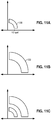
- an original image may include a key having a Fourier domain shape shown in Fig. 9A .
- the key shape may bulge, e.g., resulting in the Fourier domain representation shown in Fig. 9B .
- the transformation, from Fig. 9A to 9B reveals the apparent transformation of the image as viewed by the camera (e.g., affine and perspective warping).
- a programmed processor e.g., in a smartphone can perform a brute-force search for an arc-like feature in Fourier space, and then sleuth corresponding warp parameters of the image from the shape of the discovered arc.
- Another approach employs Fourier-Mellin-based processing to locate the distorted arc zone within Fourier domain image data, using technology akin to that that detailed in patents 6,408,082 and 6,590,996 .
- the detailed keys are typically conspicuous in Fourier space, allowing ready determination of warp parameters by such methods - at least in a gross sense.
- a rough sense of the image viewing perspective is thereby discerned (e.g., to within 5 or 10 degrees)
- the image data can be resampled accordingly, e.g., as if captured from an on-axis camera perspective.
- calibration signals commonly found in digital watermark signals can be used to resolve remaining small distortions in the resampled imagery, allowing accurate reading of large payload watermark data.
- calibration signals in the cited watermark technology serve as a search-space accelerator.
- the key technology detailed herein can be viewed as a supplemental calibration signal, and detectors may be tuned to search off-axis camera angles. Keys for this purpose can take the form of paired staggered strings of pearl-like-features in the Fourier Y-B magnitude space (i.e., two concentric rings of peaks in the Fourier domain, such as shown in Fig. 12 ).
- the detector can then apply a family of templates - corresponding to these key features (or other known key features) as they would appear in the Fourier domain if the image is viewed in stepped angles off-axis (e.g., in 5 degree steps, from 0 to 45 degrees) and employing Fourier-Mellin analysis.
- This operation is suitable for quick performance by a cloud-based processor, e.g., in 250 ms or less.
- the smartphone can send a 32x32 pixel region from the center of the camera view to the cloud processor (either in the pixel domain, or after transforming to Fourier space - possibly with compression that does not corrupt the watermark signal).
- the cloud processor applies the cited templates to the received data to locate the key signal, and returns an estimate of the viewing angle to the phone.
- the phone then resamples the image in accordance with this estimated viewing angle, and applies the cited watermark decoding process to extract the watermark payload.
- the keys can be designed to have "fragile" properties, so as to aid in image/document authentication.
- the hidden keys can be composed of spectral frequencies that are at or near the high frequency limit for imaging sensors to detect. The magnitudes of these signals can also be tailored so that the keys are barely detectable in the original image. If such an original image is scanned and re-printed, this low amplitude and/or high frequency data will likely degrade so that it is no longer detectable.
- CCD, CMOS and other image sensors can be designed with such technology in mind, to achieve desired properties in the combined system.
- a smartphone can capture a frame of imagery from print media or another screen and, by reference to a watermark decoded from the imagery or other auxiliary data, overlay a graphic showing a touchpad. The user can touch the different buttons displayed on the screen.
- the touch-sensitive screen provides output coordinate data by which pixel regions in the captured imagery corresponding to these touches can be determined. Hidden keys detected at these regions in the captured imagery are noted, and the sequence of such keys defines the "combination" or other code entered by the user (e.g., CK4, CK2, CK5, CK9). If the entered code matches a stored sequence, an action can be taken. Or other action can be taken in accordance with the keystrokes (e.g., reprogramming a thermostat, such as detailed in published application 20100261465 ).
- the outlines of the hidden keys are discerned from the captured image, and made visible as graphic overlays. Again, these can be touched in a desired sequence.
- responsive action can be taken.
- the graphic overlay can change as further keys are touched.
- the auxiliary data is not necessary.
- the different keys can be ascribed meaning by a known reference, such as a data table stored in the smartphone or elsewhere - not pointed-to or otherwise indicated by auxiliary data. When a key is detected, the reference is consulted to determine what behavior should be performed.
- any number of other image transforms may alternatively be employed. Examples include DCT, wavelet, Haar, Hough, etc.
- tonal signatures such as the chord progression illustrated in Fig. 1A
- chord progression can be used as a quick check of the authenticity, or other attribute, of an image.
- segmented arc regions are the areas shown in solid black Figs. 5 and 6 . These zones do not encompass the origin of the complex plane - so if mirrored about the axes, there would be a gap at the center.
- a segmented arc region typically is characterized, in part, by an arc segment that serves as part of a bounding perimeter, a non-zero distance away from the origin - corresponding to a minimum image frequency. Practically speaking, the segmented arc region is likewise bounded by an outer perimeter that is a finite radius from the origin - indicating the maximum image frequency.
- a segmented arc region typically does not encompass any part of the horizontal ( u ) or vertical ( v ) axes. In a particular implementation there may be one segmented arc region, or there may be several. (In many instances such regions may be mirrored around an axis, such as the v axis.
- the added/subtracted signal energy is typically placed within a segmented arc region. However, it need not fully occupy the region.
- An example is shown in the transform domain plane 100 of Fig. 10A .
- the arc region 102 is defined by an inner perimeter 104 and an outer perimeter 106. This region 102 does not include the origin 108. Nor does it include the horizontal or vertical axes 110, 112.
- Within this segmented arc region 102 are one or more spatial frequency zones 114 that are increased in spectral energy. Each such zone typically comprises more than a single frequency (e.g., an impulse function), although a single frequency can be used in variant embodiments.
- Each zone commonly has extent in at least one, and usually two, directions in the transform plane.
- Fig. 10A has certain symmetry (e.g., around axis 116), this is not required.
- Fig. 10B shows another arrangement. Non-symmetrical arrangements are desirable in various instances.
- Figs. 11A and 11B show one such arrangement.
- Fig. 11A shows a first zone 130.
- Fig. 11B shows a second zone 132.
- Zone 132 comprises frequencies that are twice the frequencies of zone 130. Further harmonics may similarly be used.
- Zone 130 may represent a least significant bit, e.g., corresponding to "1" in decimal.
- Zone 132 may represent a next-least significant bit, e.g., corresponding to "2" in decimal.
- the addition of signal energy in both zones, as in Fig. 11C thus corresponds to "3" in decimal, etc.
- signal energy added to one chrominance channel is matched, in a complementary fashion, by subtraction of signal energy from the other chrominance channel.
- Such form of embedding is further detailed in published patent application 20100150434 .
- This approach allows use of lower frequency chrominance signals without visible degradation, and yields increased signal-to-noise ratio in the detector when processed according to the cited teachings.
- the complementary subtraction operation can be applied to the same frame, or to a next frame in the video sequence.
- a contiguous key region encompasses less than 10%, 5%, 3% or 1.5% of the entire image frame.
- the hidden keys can be represented in visible fashion on the user's screen, such as by dashed outlines, distinctive cross-hatching, etc., so as to indicate the shapes to the user. These can be dragged and resized in known fashion, using tools such as have been popularized by Adobe.
- the authoring software can further include a print-preview feature that renders the imagery on the screen, including the keys in their hidden form - approximating any color space transformation and other distortions inherent in the printing workflow.
- the software may include a viewing mode in which two views (authoring and print-preview) are presented side-by-side.
- Corresponding test application software can be provided for a smartphone used by the artist, which senses the added keys from imagery, and provides quantitative data back to the artist. As changes are made to the artwork, this software application can provide immediate feedback. Diagnostic windows can be displayed on the smartphone screen, or the authoring terminal (to which the phone may be linked wirelessly, or by USB or the like). These diagnostic windows can indicate key signal strengths, apparent sizes of key regions, confidence levels for key detection, etc.
- a smartphone presents a display that includes both natural imagery captured by the camera, as well as transform-domain information (e.g., in the spatial-frequency, or Fourier, domain) based on camera-captured imagery.
- transform-domain information e.g., in the spatial-frequency, or Fourier, domain
- reference signals that can be encoded into imagery to aid a steganographic watermark detector in determining whether a watermark is present.
- Those reference signals are encoded in the spatial-frequency domain - at sufficiently high frequencies, and/or with a chrominance - that causes them to be imperceptible to casual human viewers.
- certain such transform domain-based information is revealed to the viewer.
- Fig. 13 shows an exemplary spatial-frequency domain view of a reference signal 210 that is added to printed host imagery, with the real components represented by the horizontal axis, and the imaginary components represented by the vertical axis (the so-called " u , v " plane).
- the illustrated reference signal comprises pentagonal constellations 212 of spatial domain impulses at frequencies (i.e., distances from the origin) that are too high for humans to perceive, but that are detectable in data produced by the image sensor in a smartphone camera.
- the corresponding spatial-frequency domain view of the host imagery is not shown in Fig. 13 , but would typically comprise signal scattered throughout the u,v plane - largely concentrated along the horizontal and vertical axes.
- the markers 212 are centered on a circle 215.
- the limit of human vision is shown by a smaller circle 217.
- Features composed of spatial-frequency components outside of circle 217 e.g., markers 212 are too high in frequency to be discernible to human viewers.
- the markers 212 were lower in spatial-frequency, they would correspond to a pixel pattern that is akin to a fine herringbone weave. At higher frequencies, however, the eye can't distinguish a weave pattern. Rather, the weave dissolves into apparent flatness.
- pentagonal marker constellations 212 While four pentagonal marker constellations 212 are shown, of course a lesser or greater number can also be used. Similarly, the markers needn't be pentagonal in form.
- a smartphone camera When a smartphone camera detects reference pattern 210, it can thereby discern the relative distance between the camera and the printed object, and any rotation and tilt of the camera relative to the object. For example, if the camera is moved closer to the object, the enlarged image components are sensed as having lower component spatial frequencies. Thus, the pentagonal markers move closer to the origin. If the camera is rotated (relative to the orientation at which the reference signal was originally encoded in the host imagery), the pentagonal markers appear similarly rotated. If the camera is tilted - so that part of the printed imagery is closer to the sensor than other parts of the printed imagery - the pattern of pentagons is skewed. (No longer do their centers 214 fall on a circle 215 centered about the u,v origin; instead, they fall on an ellipse.)
- Fig. 14 shows an exemplary smartphone display 220.
- the smartphone is imaging part of a cereal box - the artwork 222 of which occupies most of the screen. Superimposed on the screen is a half-plane depiction of the detected reference signal, including the top two pentagonal reference markers.
- the illustrated display also includes two fixed target regions 224 - outlined in circular dashed lines. By moving the phone towards or away from the cereal box, and tilting/rotating as necessary, the user can cause the pentagonal markers 212 to move into the two targeting regions 224. At this position, reading of the watermark signal from the cereal box is optimized (i.e., the smartphone camera is positioned to capture a plan view of the box). The smartphone will read the watermark immediately (likely before the markers are aligned in the targeting regions), and the phone will take a corresponding action in response to the detected data.
- the transform domain overlay is presented at a visibility (strength) that varies with strength of the detected reference signal. If no reference signal is detected (e.g., by a detection metric output by a pattern detector), then no overlay is presented. With stronger signals, the overlaid marker signals are presented with greater contrast - compared to the background image 222. In some embodiments, the markers are presented with coloration that varies in chrominance or luminosity, depending on strength of the detected reference signal.
- the spatial-frequency representation of the captured imagery is thresholded, so that any spatial-frequency component below a threshold value is not displayed. This prevents the display from being degraded by a Fourier domain representation of the captured cereal box artwork 222. Instead, the only overlaid signal corresponds to the marker signals.
- the spatial-frequency data may be high-pass spectrally-filtered, so only image components that are above a threshold spatial frequency (e.g., the spatial frequency indicated by circle 217 in Fig. 13 ) are shown.
- a threshold spatial frequency e.g., the spatial frequency indicated by circle 217 in Fig. 13
- the circular target regions 224 are not essential. Other visual guides can be presented, or they can be omitted entirely. In the latter case, the user may be instructed to position the phone so that the markers 224 are even (i.e., horizontally-across). If the transformed data is spectrally-filtered (as described in the preceding paragraph), then the user may be instructed to position the phone towards- or away- from the subject until the markers just appear.
- the five points of the markers 212 look a bit like little pixie figures - a head, two hands and two feet, especially when rendered in color. The user can thus be instructed to "look for the pixie people." Their appearance can be made particularly noticeable by giving the five component elements of each marker different colors, and change the colors over time - yielding an engaging, shimmering effect.
- the spatial-frequency information is shown in a rectangular box 226.
- this box also serves to define a rectangular sub-region of pixels within the artwork 222, on which the transform domain analysis is performed. That is, instead of converting the entire frame of imagery into the Fourier domain, only those pixels within the box 226 are so-converted. This reduces the burden on the phone processor.
- the box 226 may be regarded as the fovea region - the sub-region of pixels on which the processor focuses its attention as it helps the user optimally position the phone.
- the luminance of pixels in region 226 can be slightly increased or decreased - to further highlight the region to the user.
- Particularly contemplated smartphones include the Apple iPhone 4, and smartphones following Google's Android specification (e.g., the Verizon Droid Eris phone, manufactured by HTC Corp., and the Motorola Droid 2 phone).
- Google's Android specification e.g., the Verizon Droid Eris phone, manufactured by HTC Corp., and the Motorola Droid 2 phone.
- the term “smartphone” (or “cell phone”) should be construed to encompass all such devices, even those that are not strictly-speaking cellular, nor telephones.
- each includes one or more processors, one or more memories (e.g. RAM), storage (e.g., a disk or flash memory), a user interface (which may include, e.g., a keypad, a TFT LCD or OLED display screen, touch or other gesture sensors, a camera or other optical sensor, a compass sensor, a 3D magnetometer, a 3-axis accelerometer, one or more microphones, etc., together with software instructions for providing a graphical user interface), interconnections between these elements (e.g., buses), and an interface for communicating with other devices (which may be wireless, such as GSM, CDMA, W-CDMA, CDMA2000, TDMA, EV-DO, HSDPA, WiFi, WiMax, or Bluetooth, and/or wired, such as through an Ethernet local area network, a T-1 internet connection, etc.).
- memories e.g. RAM
- storage e.g., a disk or flash memory
- a user interface which may include, e.g.,
- the processes and system components detailed in this specification may be implemented as instructions for computing devices, including general purpose processor instructions for a variety of programmable processors, including microprocessors (e.g., the Atom and A4), graphics processing units (GPUs, such as the nVidia Tegra APX 2600), and digital signal processors (e.g., the Texas Instruments TMS320 series devices), etc. These instructions may be implemented as software, firmware, etc. These instructions can also be implemented in various forms of processor circuitry, including programmable logic devices, field programmable gate arrays (e.g., the Xilinx Virtex series devices), field programmable object arrays, and application specific circuits - including digital, analog and mixed analog/digital circuitry.
- microprocessors e.g., the Atom and A4
- GPUs graphics processing units
- digital signal processors e.g., the Texas Instruments TMS320 series devices
- These instructions may be implemented as software, firmware, etc.
- These instructions can also be implemented in various forms of
- Execution of the instructions can be distributed among processors and/or made parallel across processors within a device or across a network of devices. Processing of content signal data may also be distributed among different processor and memory devices. "Cloud” computing resources can be used as well. References to "processors,” “components,” and the like should be understood to refer to functionality, rather than requiring a particular form of implementation.
- the service by which content owners ascribe certain attributes and experiences to content typically uses software on the user device - either in the OS or as application software. Alternatively, this service can be implemented - in part - using remote resources.
- Software and hardware configuration data/instructions are commonly stored as instructions in one or more data structures conveyed by tangible media, such as magnetic or optical discs, memory cards, ROM, etc., which may be accessed across a network.
- Some embodiments may be implemented as embedded systems - a special purpose computer system in which the operating system software and the application software is indistinguishable to the user (e.g., as is commonly the case in basic cell phones).
- the functionality detailed in this specification can be implemented in operating system software, application software and/or as embedded system software.
- such altered imagery is transmitted or stored, together with different auxiliary information.
- the encoded chroma key(s), in conjunction with the auxiliary information serve to cooperatively define a response to the image sub-region when the sub-region sensed by a mobile device including an image sensor.
- Another arrangement is a method employing a portable user device that includes a processor portion, and a camera portion.
- the method includes transforming imagery captured by the camera portion to yield corresponding data in a transform domain.
- This transform domain information is then analyzed to detect the presence of signal energy (a "key") in a segmented arc region of the transform domain.
- the method additionally includes receiving plural-bit auxiliary data and, through use of such plural-bit auxiliary data, determining a response corresponding to the detected key.
- Yet another arrangement includes capturing image data from a scene using a sensor (e.g., in a smartphone camera); computing a transform-domain representation of at least part of said scene; and presenting on a screen a representation based on said transform-domain representation.
- a sensor e.g., in a smartphone camera
- computing a transform-domain representation of at least part of said scene e.g., in a smartphone camera
- presenting on a screen a representation based on said transform-domain representation can include pixels - the positions of which are based on spatial frequency attributes of the captured image data.
- such a representation can include pixels - the luminance or color of which are based on amplitudes of spatial frequency coefficients of the transformed image data.
- Still another arrangement includes capturing image data from an object using a sensor (e.g., in a smartphone camera); computing a transform-domain representation based on at least part of the captured image data; presenting on a screen a display that is based on said transform-domain representation; and guiding a user in moving the sensor relative to the object, by reference to said presented transform-domain representation.
- a sensor e.g., in a smartphone camera
- computing a transform-domain representation based on at least part of the captured image data
- presenting on a screen a display that is based on said transform-domain representation and guiding a user in moving the sensor relative to the object, by reference to said presented transform-domain representation.
- Yet another arrangement includes capturing image data from a scene using a device that includes a 2D image sensor, where the sensor has a uniform density of sensing elements thereacross (e.g., as in a conventional CMOS or CCD sensor); applying a foveal filtering function to the image data, wherein a sparser sampling of image data is retained outside a foveal zone (as compared to a denser sampling of image data that is retained within the foveal zone); and further processing the foveal-filtered image data.
- a device that includes a 2D image sensor, where the sensor has a uniform density of sensing elements thereacross (e.g., as in a conventional CMOS or CCD sensor); applying a foveal filtering function to the image data, wherein a sparser sampling of image data is retained outside a foveal zone (as compared to a denser sampling of image data that is retained within the foveal zone); and further processing the foveal-filtered image data.
Description
- The present technology includes improvements to, and in different embodiments makes use of, assignee's earlier work detailed in
U.S. patents 6,122,403 ,6,408,082 and6,590,996 , and published applications20060115110 ,20070189533 ,20080112596 ,20080300011 ,20090116683 ,20100046842 ,20100048242 ,20100150434 ,20100317399 ,20100261465 ,20110098029 ,20100165158 ,20110098056 and20100228632 . The reader is presumed to be familiar with such prior work, and able to incorporate such teachings into implementations utilizing the presently-detailed technology. - The present technology primarily concerns smartphone interactions with images - such as are found on printed objects.
- Smartphones are increasingly being used with "visual search" applications. One visual search application decodes digital watermark data steganographically encoded (i.e., hidden) in printed imagery (such as in a magazine or on product packaging) and enables the phone to link to associated information and services, or take other action. Exemplary digital watermark technology, and visual search applications, are detailed in the above-cited patent documents.
- Perspective distortion can sometimes interfere with proper decoding of digital watermark data. That is, if a watermarked object is imaged by a smartphone at a relatively large off-axis angle (e.g., greater than 15 or 30 degrees), the hidden watermark data may be sufficiently distorted by the perspective viewing angle that the decoding algorithm does not recognize it.
- A related concern is consumer confusion. If a consumer uses a smartphone to image a magazine page, and no watermark is promptly detected, is it because the page does not include a watermark to which the smartphone should respond? Or is it because the magazine page is presented with an unsuitable perspective?
KR 100 776 663 B1 - It is also desirable to assist consumers in capturing imagery that has relatively little perspective distortion (e.g., less than 15 or 30 degrees).
- In accordance with one aspect of the present technology, the presence of hidden data is reliably detected notwithstanding perspective angles exceeding 30, 45, or 60 degrees, or more.
- In accordance with another aspect of the present technology, a smartphone provides feedback (e.g., on a display screen) that aids a user in positioning the smartphone so that the captured imagery has relatively little perspective distortion.
- The foregoing and many other features and advantages of the present technology will be more readily apparent from the following detailed description, which proceeds by reference to the accompanying drawings. The scope of the invention is defined by its independent claims.
-
-
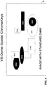
Fig. 1 shows an image including plural hotspot regions encoded with various keys. These may be regarded as YB-Dome spatial chromakeys. Depicted are spatially overlapping "analog" chroma-encoded regions. These are essentially "invisible" to the human eye, but seen by a digital watermark detector. -
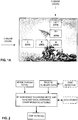
Fig. 1A shows another image similar toFig. 1 , with which a smartphone can interact to yield different musical sounds. -
Fig. 2 is a flow chart of a method that can be used in conjunction with the image ofFig. 1A . -
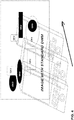
Fig. 3 is an illustration showing some of the different behaviors that can be triggered in a smart phone by detection of one or more hotspot regions in the image ofFig. 1 . Depicted are both an audio-mode, and a HotMap (GLO) mode. -
Fig. 4 shows that user interaction with imagery encoded in accordance with the present technology can employ motion. -
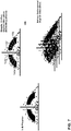
Fig. 5 illustrates decomposition of an image into luminance and dual chrominance channels in the spatial frequency domain, and embedding of a key in the Y-B channel. Particularly detailed is allocation of the YB-Dome signal space, including how such signal can take over certain frequency bands - with no need to share with existing artwork. -
Fig. 6 is a chart showing the sensitivity of the human visual system to the three channels ofFig. 5 , as a function of image spatial frequency. -
Fig. 7 illustrates that plural different keys can be encoded within a single chrominance channel. -
Fig. 8 shows that a sub-region of smartphone's field of view can be used to detect keys in imagery. -
Figs. 9A and 9B show how a key may be warped by perspective or other distortion of the image, allowing such distortion to be determined. -
Figs. 10A and 10B show different spectral signal energies within a segmented arc in Fourier space that can be employed to represent keys. -
Figs. 11A-11C illustrate that keys can have harmonic relationships, and can be used in connection with binary encoding. -
Fig. 12 shows another key representation in Fourier space. -
Fig. 13 shows still other marker signals in a spatial-frequency domain. -
Fig. 14 shows a mixed-domain view of a printed object that includes the marker signals ofFig. 13 . - As shown in
Fig. 1 , animage 10 is encoded in accordance with one aspect of the technology to define one or more regions (CK1, CK2, etc.) that can be sensed by a suitably-equipped mobile device (e.g., a smartphone/cell phone), but are imperceptible to humans. When such a mobile device senses one of these regions, it takes an action in response. - The content of
image 10 can be arbitrary. Details (except the hidden regions) are not shown for clarity of illustration. - The regions can be of any shape; only a few are illustrated. As indicated, they may overlap in layered fashion. Each region has a key associated with it (e.g., CK1, CK2, etc.). Because the preferred embodiment employs a chrominance-based embedding arrangement, these keys may be termed chroma keys. However, other embedding arrangements can alternatively be used.
- ("YB" in the drawing title refers to Yellow-Blue. "Dome" refers to an arc-shaped area in Fourier-space in which the keys are manifested, as detailed further below.)
-
Fig. 1A shows an exemplary illustration, employing 7 regions, hidden in the iconic Iwo Jima photograph but shown as visible for explanatory purposes. When the left-most region is sensed by a smartphone, it renders a musical note at the pitch "C." The adjacent region causes the phone to render a pitch at "E." Similarly with the next one, at "G." - The top-most region similarly causes the phone to render a musical note at the pitch "C." Beneath it, however, is a region that causes the phone to render the musical note E. Below is the "G" region noted above.

- If a user sweeps a suitably-programmed smartphone horizontally across the image from left left to right, so that the phone's camera "sees" the horizontal row of regions in sequence, a C-major chord progression is sounded. Conversely, if the user sweeps the phone vertically, downwardly, across the indicated regions in the image, a C-minor chord progression is sounded.
- More particularly, in this example the regions are encoded with four different keys. The same key (CK1) is used for both the left-most and top-most regions, since they both correspond to the same musical tone. Different keys CK2, CK3 and CK4, are used for the other three regions.
- In the illustrated example,
image 10 also is digitally watermarked (DWM) in known fashion to steganographically convey a plural-bit payload of auxiliary data (e.g., 32- or 128-bits) - although this is not always required. These plural bits can identify a data structure that is consulted by the smartphone in determining what response should be associated with which key. - Identification of the data structure by the plural bit auxiliary data can be by various means. One is a pointer (e.g., an address) to a local or remote table, or database record. In this instance, the data structure indicates that if CK1 is detected, the phone should render a musical tone of "C" (i.e., 262 Hz). A complete table may instruct the phone to respond to different keys as follows:
Table I CK1 Render 262 Hz tone CK2 Render 330 Hz tone CK3 Render 392 Hz tone CK4 Render 311 Hz tone - This table is exemplary only, and the illustrative responses are more basic than may often occur - simply for expository convenience.
- A tone may sound for a fixed duration, e.g., 1 second, commencing with initial detection of the corresponding key region, or it may persist for as long as the region is within the field of view of the smartphone camera. In the latter case, chords of plural notes can be rendered by positioning the camera so that it can view some - or all - of the depicted regions. The chord is augmented with more notes as the camera is moved away from the image, and resolves to fewer notes as the camera is moved closer.
- The use of auxiliary data to indicate what responses should be associated with different keys allows simple dynamic reprogramming of the user experience, even with a "fixed" image. For example, by simply changing data in the table to which the illustrative auxiliary data (watermark) points, the image can trigger a wholly different set of responses - all without modification of the imagery.
- A flow chart detailing the just-described method is shown in
Fig. 2 . -
Figs. 3 and4 further illustrate the just-discussed feature, by which a smartphone camera detects different hidden regions in an image, and can yield different outputs as the phone is moved. - "GLO" in
Fig. 3 is an acronym for Graphic Latent Overlay. This technology is detailed in documents including published patent specifications20080300011 20090116683 - Related technologies are detailed in patent publications
20110098029 20110098056 - Thus, instead of playing a musical tone when a key region is sensed, the phone can respond by overlaying a graphical display on the captured imagery.
- Of course, playing musical tones and overlaying graphical displays are a few of countless behaviors that detection of a key region can trigger. Any imaginable action or script can be similarly triggered when one or more of the hidden regions (which may be regarded as "hotspots") is sensed.
- Consider, as a particular example, a photo of members of a hockey team. The oval region of each player's face is marked with a different hidden key, CK1 - CK20. When a user directs the smartphone camera to a particular player's face, the corresponding key is detected. A watermark is also detected from the image (and may span the entire image). The watermark payload points to a table, like Table I above, having an entry for each of keys CK1 - CK20. This table, in turn, may store links to Flash video presentations, resident at an NHL web server or in the cloud, that show season highlights for that respective player. When the user moves the smartphone camera to view different faces in the team picture, different video plays from the past season are rendered on the user's phone.
- (The watermark payload can serve other purposes as well. For example, the payload can include one or more flag bits instructing the smartphone not to provide a response if plural keys are detected within the captured imagery. Alternatively, they may instruct the smartphone to prompt the user to more closely direct the camera to one particular feature (face) in the image. All prior art uses of watermark signaling can also be employed in conjunction with the present arrangements.)
- While images are commonly perceived in the spatial (or pixel) domain, a number of other representations are also useful, as is familiar to those skilled in the art. Generally, these other representations are termed "transform domains." One popular transform domain is Fourier space (commonly called the spatial frequency domain, when used with images). By applying, e.g., a discrete Fourier transform (DFT), or a discrete cosine transform (DCT) to an image (either as a whole, or more commonly as divided into square regions, e.g., 8x8 pixels or 32x32 pixels), the image is decomposed into a set of coefficients - each indicating an amplitude of a corresponding spatial-frequency component. The resulting set of information can be depicted on a complex half-plane coordinate system, as shown in
Fig. 5 . - The left part of
Fig. 5 shows a representative spatial frequency domain representation of a sample image (e.g., the Iwo Jima image earlier presented). This image is encoded with a prior art digital watermark that conveys auxiliary data. (A suitable watermark is detailed in patent6,590,996 Fig. 5 . - The image may be divided into component image planes, such as luminance, and dual chrominance channels: R-G (red-green) and Y-B (yellow-blue) - each of which has its own Fourier space representation. These three channels, in Fourier-space, are shown at the right side of
Fig. 5 . - In the illustrated embodiment, the encoding of the keys into regions of the image is achieved by adding energy in one of the chrominance channels (e.g., Y-B). This can be done without objectionable visible effect because the human visual system (HVS) is less sensitive to color than it is to luminance.
- This is shown in
Fig. 6 , which plots HVS sensitivity for luminance, red-green chrominance, and yellow-blue chrominance, as a function of spatial frequency, in cycles per degree. (This chart is based on data collected at a viewing distance of 12 inches.) As can be seen, HVS sensitivity drops off sharply at chrominance spatial frequencies above 10 cycles per degree (cpd), and is down dramatically at 20 cycles per degree. Sensitivity above 25 or 30 cycles per degree is essentially nil. - In contrast, image sensors used in cameras can commonly distinguish chrominance features at such spatial frequencies.
- Thus, to encode a key in an image region, such as CK1 in
Figs. 1 or1A , energy can be added to the yellow-blue chrominance channel, desirably at frequencies of above 10, 20, 25 or 30 cpd - where the effect is generally not noticeable to human observers, but can readily detected from optical sensor data. - In the preferred embodiment the added energy needn't be exclusively above the indicated frequency. But desirably most of the added energy is in that range (e.g., more than 50%, 75%, 95%, or 98%).
- In this embodiment, and in others, the magnitude of the added energy can also be scaled to achieve a desired level of visibility (or invisibility). In other embodiments, signal energy at frequencies primarily below 10 cpd can be employed, if the magnitude of the added energy is low enough to be visually un-objectionable.
- One example of suitable encoding, in Fourier space, is shown in the lower right of
Fig. 5 by the black bands. This added signal energy dominates existing image energy in these spectral frequencies (including phase), but the effect typically is essentially imperceptible to human viewers. The effect is to slice out a region in chrominance space and allocate it to representing a hidden a key. Thus encoded, a suitably-equipped smartphone detector can quickly discover the presence of the hidden region in the image, and determine its extent, and respond to such discovery. - In many instances it is desirable to be able to distinguish different keys, such as CK1, CK2, etc., in
Fig. 1 . This can be done by representing different keys with different Fourier domain zones of signal energy in the chosen (e.g., Y-B) chrominance channel (including phase). Such arrangement is shown in the upper right ofFig. 7 . - In particular, this spatial domain plot shows 10 keys, 150a through 150j. In
Fig. 1 , region CK1 can be encoded by adding signal energy corresponding to the keystone-shapedFourier zone 150a to that image region. Likewise, image regions CK2 - CK5 can be encoded by adding energy at spatial frequencies indicated by keystone zones 150b - 150e. Five additional keys can be represented by adding energy corresponding to the spatial frequency zones labeled 150f - 150j. (It will be recognized that the discussed plot encompasses ten different keys. A particular region of the imagery would not necessarily have this depicted signal composition in Fourier space. More likely, only one or a few of the keystone features would be present.) - Again, the illustrations do not show phase, which is a helpful dimension of these hidden signals. The phase component contributes certainty to detection of these keys (i.e., increasing signal-to-noise ratio).
- In one particular embodiment, different keys may be of opposite phase polarity (analogous to +1/-1). One key, CK-a, may be represented by the
keystone zone 150a with a certain phase profile across the zone, and another key, CK-b, may be represented by energy in thesame keystone zone 150a, but with a phase profile that is 180 degrees out of phase relative to key CK-a. This results in a doubling of the keyspace (e.g., the tenzones 150a-150j can represent 20 distinguishable keys). - A further multiple-key arrangement is shown in the lower right of
Fig. 7 . Here N mutually-orthogonal signals in Fourier space are employed. For purposes of illustration, a simple example is for one signal to be a sine wave at an image frequency f. Another may comprise a cosine signal at the same frequency. A third may comprise a sine signal at a frequency 2f. Etc. (The design of orthogonal signals in Fourier space is within the capability of the artisan, although such signals are difficult to represent in simple drawings. In one view, two keys are orthogonal if the product of their phase profiles yields zero.) - Typically, all keys in an image are encoded at the same magnitude, usually at a level that renders the keys imperceptible to humans in the rendered imagery. Having a uniform magnitude across all keys can be useful in detection, since detection of one key provides magnitude information that can be used to help discriminate the presence of other keys.
- In some embodiments, certain keys may have different magnitudes (e.g., they may be partially "on"). This can be used to further expand the encoding space. E.g., key CK-c can have a magnitude that is half that of key CK-d, but the keys are otherwise the same in spectral frequency content and phase profile. Instead of binary values of single keys (e.g., +phase and -phase), quaternary and other multi-valued symbols can be used.
- If the relations between different magnitudes are known by the detector (e.g., some keys are 100% "on"; other keys are 50% "on," and still others are 25% "on,"), this knowledge can again be used as a basis in discriminating keys. (These may be regarded as "analog keys.")
- In a system employing multiple keys, each can trigger a different action (e.g., different tones in the
Fig. 1A example). Still further actions can be triggered when multiple keys are overlaid in an image region (e.g., where CK5 overlaps CK1 inFig. 1 ). Thus, in a 10 key system, there may be ten responses corresponding to the ten individual keys. Nine further responses can correspond to regions where key 1 is overlaid with one of keys 2-10. Eight further responses can correspond to where key 2 is overlaid with keys 3-10. Seven further responses can correspond to where key 3 coexists with keys 4-10. Etc. Thus, in a system that contemplates only layers of up to two keys, 55 different states can be defined. (A geometric increase of possible states naturally occurs if three-or more keys are overlaid.) - If the keys have different magnitudes, the responses triggered by the keys can vary accordingly. In the tonal example of
Fig. 1A , for example, if key CK3 is half the magnitude of the other keys, then its corresponding tone may be rendered at half the volume of those triggered by the other keys. - The smartphone detector can apply Fourier-domain templates for the different keys it expects to encounter - looking for the existence of the hidden signals. This can comprise a correlation detector that performs multiplications with each of the respective key templates - judging whether resultant output signals exceed a threshold value.
- The template(s) can encompass more of Fourier space than the precise boundaries of the sought-for key(s), allowing detection of keys in the case of distortion of the imagery (with consequent distortion of the keys in Fourier space).
- Typically, smartphone cameras have a rectangular field of view (e.g., 2048 x 1536 pixels). In some instances it is desirable for the smartphone camera to be responsive to keys only in a sub-region of this field of view. Such an arrangement is shown in
Fig. 8 , in which the full camera field of view is theimage frame 190, yet responses are only triggered by keys found within thesub-region 192. The shape of the sub-region can be arbitrary; the illustrated rectangle (of about 250 pixels in width by about 900 in height) is only exemplary. - In another arrangement, the
zone 192 is circular or oval. Moreover, the software that controls use of sampled image data fromregion 192 can apply a foveal filter: using all the pixels at the center of the region for most acute detection, but using a sparser sampling of pixels near a periphery of theregion 192, so that sensitivity or acuity tapers off. (Instead of discarding more remote pixels from consideration, groups of outlying pixels may be averaged to yield a foveal effect: dense pixel information in the center of the zone, and lower resolution pixel information at greater distances.) - (Such foveal filtering can be a preamble to many different types of image processing, including feature and object recognition, machine vision, watermark decoding, fingerprint calculation, image-based context determination, and the other types of processing detailed in the earlier-cited patent publications.)
- A camera-equipped detector using the present technology can discern the spatial extent of key regions, e.g., identifying region boundaries to an accuracy of tens of imaged pixels or less (e.g., 5 to 10 "waxels" - watermark signal elements). The detector can thus "image" the hidden keys, e.g., generating a virtual map of their locations within the imagery.
- If the geometrical shapes of the keys are known in advance (e.g., if keys are circular, or square, or equilateral triangles), then their shapes in the captured imagery can be used to characterize any off-axis viewing of the image. This information, in turn, can be used to aid detection of any watermark signal encoded in the imagery.
- For example, the device processor can re-sample the image data in correspondence with distortion of the known key shapes. If the key is known to include two parallel edges of the same length, yet a first edge appears in the captured imagery to be 50% shorter than a second edge, then image points along the first edge can be resampled by the processor at a spatial frequency twice those alone the second edge - with interpolated sampling rates being used along intermediate parallel lines. The watermark decoding process can then be applied to the resampled image - from which this aspect of a perspective warp has been effectively removed.
- A more sophisticated approach to dealing with perspective does not require knowledge of geometrical key shapes. Rather, it relies on knowledge of a key's Fourier domain representation.
- To illustrate, an original image may include a key having a Fourier domain shape shown in
Fig. 9A . If the image is captured from an off-axis perspective, the key shape may bulge, e.g., resulting in the Fourier domain representation shown inFig. 9B . The transformation, fromFig. 9A to 9B , reveals the apparent transformation of the image as viewed by the camera (e.g., affine and perspective warping). - A programmed processor (e.g., in a smartphone) can perform a brute-force search for an arc-like feature in Fourier space, and then sleuth corresponding warp parameters of the image from the shape of the discovered arc. Another approach employs Fourier-Mellin-based processing to locate the distorted arc zone within Fourier domain image data, using technology akin to that that detailed in patents
6,408,082 6,590,996 - The detailed keys are typically conspicuous in Fourier space, allowing ready determination of warp parameters by such methods - at least in a gross sense. Once a rough sense of the image viewing perspective is thereby discerned (e.g., to within 5 or 10 degrees), the image data can be resampled accordingly, e.g., as if captured from an on-axis camera perspective. Then calibration signals commonly found in digital watermark signals (e.g., per the just-cited patents) can be used to resolve remaining small distortions in the resampled imagery, allowing accurate reading of large payload watermark data.
- The artisan will recognize that calibration signals in the cited watermark technology serve as a search-space accelerator. The key technology detailed herein can be viewed as a supplemental calibration signal, and detectors may be tuned to search off-axis camera angles. Keys for this purpose can take the form of paired staggered strings of pearl-like-features in the Fourier Y-B magnitude space (i.e., two concentric rings of peaks in the Fourier domain, such as shown in
Fig. 12 ). The detector can then apply a family of templates - corresponding to these key features (or other known key features) as they would appear in the Fourier domain if the image is viewed in stepped angles off-axis (e.g., in 5 degree steps, from 0 to 45 degrees) and employing Fourier-Mellin analysis. - This operation is suitable for quick performance by a cloud-based processor, e.g., in 250 ms or less. The smartphone can send a 32x32 pixel region from the center of the camera view to the cloud processor (either in the pixel domain, or after transforming to Fourier space - possibly with compression that does not corrupt the watermark signal). The cloud processor, in turn, applies the cited templates to the received data to locate the key signal, and returns an estimate of the viewing angle to the phone. The phone then resamples the image in accordance with this estimated viewing angle, and applies the cited watermark decoding process to extract the watermark payload.
- (Other divisions of labor between the phone and cloud are likewise possible, e.g., with the cloud doing all of the processing including extracting the watermark payload.)
- In some embodiments, the keys can be designed to have "fragile" properties, so as to aid in image/document authentication. For example, the hidden keys can be composed of spectral frequencies that are at or near the high frequency limit for imaging sensors to detect. The magnitudes of these signals can also be tailored so that the keys are barely detectable in the original image. If such an original image is scanned and re-printed, this low amplitude and/or high frequency data will likely degrade so that it is no longer detectable. CCD, CMOS and other image sensors can be designed with such technology in mind, to achieve desired properties in the combined system.
- One application of this technology is as a keypad, e.g., akin to the sorts conventionally used to open a safe, set alarms, etc. For example, a smartphone can capture a frame of imagery from print media or another screen and, by reference to a watermark decoded from the imagery or other auxiliary data, overlay a graphic showing a touchpad. The user can touch the different buttons displayed on the screen. The touch-sensitive screen provides output coordinate data by which pixel regions in the captured imagery corresponding to these touches can be determined. Hidden keys detected at these regions in the captured imagery are noted, and the sequence of such keys defines the "combination" or other code entered by the user (e.g., CK4, CK2, CK5, CK9). If the entered code matches a stored sequence, an action can be taken. Or other action can be taken in accordance with the keystrokes (e.g., reprogramming a thermostat, such as detailed in published application
20100261465 - In a variant embodiment, the outlines of the hidden keys are discerned from the captured image, and made visible as graphic overlays. Again, these can be touched in a desired sequence. By reference to the keys, in conjunction with the watermark, responsive action can be taken.
- In a further variant, the graphic overlay can change as further keys are touched.
- Although the detailed arrangement employs digital watermarking to convey auxiliary information by which actions corresponding to sensed key regions can be determined, this is not necessary. Other communications means can be utilized, e.g., RFID chips, barcodes, header data, etc. Alternatively, a fingerprint of the imagery can be calculated, and matched with reference information in a database to identify the image, which identification can also serve to identify metadata by which associations between the keys and appropriate responses can be determined. (Examples of image/video fingerprinting are detailed in patent publications
7,020,304 7,486,827 20070253594 20080317278 20020044659 - In still other arrangements, the auxiliary data is not necessary. Instead, the different keys can be ascribed meaning by a known reference, such as a data table stored in the smartphone or elsewhere - not pointed-to or otherwise indicated by auxiliary data. When a key is detected, the reference is consulted to determine what behavior should be performed.
- While the detailed arrangements typically employ a Fourier transform (e.g., an FFT), any number of other image transforms may alternatively be employed. Examples include DCT, wavelet, Haar, Hough, etc.
- It should be recognized that tonal signatures, such as the chord progression illustrated in
Fig. 1A , can be used as a quick check of the authenticity, or other attribute, of an image. - Although reference was made to the keys being hidden or invisible, this is all a matter of degree, which can be tuned to meet the needs of particular applications. In some applications, for example, some visibility is acceptable.
- As used herein, "primarily" means more than half (50%). "Predominantly" means more than 75%. "Essentially" means more than 95%. "Almost exclusively" means more than 98%, and "exclusively" means 100%.
- Examples of segmented arc regions are the areas shown in solid black
Figs. 5 and6 . These zones do not encompass the origin of the complex plane - so if mirrored about the axes, there would be a gap at the center. Put another way, a segmented arc region typically is characterized, in part, by an arc segment that serves as part of a bounding perimeter, a non-zero distance away from the origin - corresponding to a minimum image frequency. Practically speaking, the segmented arc region is likewise bounded by an outer perimeter that is a finite radius from the origin - indicating the maximum image frequency. Likewise, a segmented arc region typically does not encompass any part of the horizontal (u) or vertical (v) axes. In a particular implementation there may be one segmented arc region, or there may be several. (In many instances such regions may be mirrored around an axis, such as the v axis. - The added/subtracted signal energy is typically placed within a segmented arc region. However, it need not fully occupy the region. An example is shown in the
transform domain plane 100 ofFig. 10A . Thearc region 102 is defined by aninner perimeter 104 and anouter perimeter 106. Thisregion 102 does not include theorigin 108. Nor does it include the horizontal orvertical axes segmented arc region 102 are one or more spatial frequency zones 114 that are increased in spectral energy. Each such zone typically comprises more than a single frequency (e.g., an impulse function), although a single frequency can be used in variant embodiments. Each zone commonly has extent in at least one, and usually two, directions in the transform plane. - Although the transform domain signal energy zones shown in
Fig. 10A have certain symmetry (e.g., around axis 116), this is not required.Fig. 10B , for example, shows another arrangement. Non-symmetrical arrangements are desirable in various instances. - In some instances, the various spatial frequency zones used in encoding an image can have harmonic relations.
Figs. 11A and 11B show one such arrangement.Fig. 11A shows afirst zone 130.Fig. 11B shows asecond zone 132.Zone 132 comprises frequencies that are twice the frequencies ofzone 130. Further harmonics may similarly be used. - Likewise, the use of different zones can be used for binary signal encoding. The
zone 130 may represent a least significant bit, e.g., corresponding to "1" in decimal.Zone 132 may represent a next-least significant bit, e.g., corresponding to "2" in decimal. The addition of signal energy in both zones, as inFig. 11C thus corresponds to "3" in decimal, etc. - In a variant embodiment, signal energy added to one chrominance channel is matched, in a complementary fashion, by subtraction of signal energy from the other chrominance channel. Such form of embedding is further detailed in published patent application
20100150434 - While it is possible to mark an entire image with a single key, more typically a sub-part of the image is so-marked. Commonly less than 20% of the image area is marked with any particular key. More typically (e.g., as shown in
Figs. 1 and1A ), a contiguous key region encompasses less than 10%, 5%, 3% or 1.5% of the entire image frame. - In practical application, artwork authoring tools such as Adobe Illustrator and the like will doubtless be employed to add keys to imagery. The hidden keys can be represented in visible fashion on the user's screen, such as by dashed outlines, distinctive cross-hatching, etc., so as to indicate the shapes to the user. These can be dragged and resized in known fashion, using tools such as have been popularized by Adobe. The authoring software can further include a print-preview feature that renders the imagery on the screen, including the keys in their hidden form - approximating any color space transformation and other distortions inherent in the printing workflow. (Different print-preview options may be provided, dependent on the type or fidelity of the print process, e.g., high resolution/fully saturated; low resolution/low saturation, etc.) The software may include a viewing mode in which two views (authoring and print-preview) are presented side-by-side.
- Corresponding test application software can be provided for a smartphone used by the artist, which senses the added keys from imagery, and provides quantitative data back to the artist. As changes are made to the artwork, this software application can provide immediate feedback. Diagnostic windows can be displayed on the smartphone screen, or the authoring terminal (to which the phone may be linked wirelessly, or by USB or the like). These diagnostic windows can indicate key signal strengths, apparent sizes of key regions, confidence levels for key detection, etc.
- In accordance with another aspect of the present technology, a smartphone presents a display that includes both natural imagery captured by the camera, as well as transform-domain information (e.g., in the spatial-frequency, or Fourier, domain) based on camera-captured imagery.
- The earlier discussion detailed illustrative reference signals that can be encoded into imagery to aid a steganographic watermark detector in determining whether a watermark is present. Those reference signals are encoded in the spatial-frequency domain - at sufficiently high frequencies, and/or with a chrominance - that causes them to be imperceptible to casual human viewers.
- In accordance with further aspects of the present technology, certain such transform domain-based information is revealed to the viewer.
-
Fig. 13 shows an exemplary spatial-frequency domain view of areference signal 210 that is added to printed host imagery, with the real components represented by the horizontal axis, and the imaginary components represented by the vertical axis (the so-called "u,v" plane). The illustrated reference signal comprisespentagonal constellations 212 of spatial domain impulses at frequencies (i.e., distances from the origin) that are too high for humans to perceive, but that are detectable in data produced by the image sensor in a smartphone camera. (The corresponding spatial-frequency domain view of the host imagery is not shown inFig. 13 , but would typically comprise signal scattered throughout the u,v plane - largely concentrated along the horizontal and vertical axes.) - In the
Fig. 13 view, themarkers 212 are centered on acircle 215. The limit of human vision (in the particular color domain being used) is shown by asmaller circle 217. Features composed of spatial-frequency components outside of circle 217 (e.g., markers 212) are too high in frequency to be discernible to human viewers. (If themarkers 212 were lower in spatial-frequency, they would correspond to a pixel pattern that is akin to a fine herringbone weave. At higher frequencies, however, the eye can't distinguish a weave pattern. Rather, the weave dissolves into apparent flatness.) - While four
pentagonal marker constellations 212 are shown, of course a lesser or greater number can also be used. Similarly, the markers needn't be pentagonal in form. - When a smartphone camera detects
reference pattern 210, it can thereby discern the relative distance between the camera and the printed object, and any rotation and tilt of the camera relative to the object. For example, if the camera is moved closer to the object, the enlarged image components are sensed as having lower component spatial frequencies. Thus, the pentagonal markers move closer to the origin. If the camera is rotated (relative to the orientation at which the reference signal was originally encoded in the host imagery), the pentagonal markers appear similarly rotated. If the camera is tilted - so that part of the printed imagery is closer to the sensor than other parts of the printed imagery - the pattern of pentagons is skewed. (No longer do their centers 214 fall on acircle 215 centered about the u,v origin; instead, they fall on an ellipse.) -
Fig. 14 shows anexemplary smartphone display 220. In this illustration, the smartphone is imaging part of a cereal box - theartwork 222 of which occupies most of the screen. Superimposed on the screen is a half-plane depiction of the detected reference signal, including the top two pentagonal reference markers. The illustrated display also includes two fixed target regions 224 - outlined in circular dashed lines. By moving the phone towards or away from the cereal box, and tilting/rotating as necessary, the user can cause thepentagonal markers 212 to move into the two targeting regions 224. At this position, reading of the watermark signal from the cereal box is optimized (i.e., the smartphone camera is positioned to capture a plan view of the box). The smartphone will read the watermark immediately (likely before the markers are aligned in the targeting regions), and the phone will take a corresponding action in response to the detected data. - Desirably, the transform domain overlay is presented at a visibility (strength) that varies with strength of the detected reference signal. If no reference signal is detected (e.g., by a detection metric output by a pattern detector), then no overlay is presented. With stronger signals, the overlaid marker signals are presented with greater contrast - compared to the
background image 222. In some embodiments, the markers are presented with coloration that varies in chrominance or luminosity, depending on strength of the detected reference signal. - In one particular implementation, the spatial-frequency representation of the captured imagery is thresholded, so that any spatial-frequency component below a threshold value is not displayed. This prevents the display from being degraded by a Fourier domain representation of the captured
cereal box artwork 222. Instead, the only overlaid signal corresponds to the marker signals. - Similarly, the spatial-frequency data may be high-pass spectrally-filtered, so only image components that are above a threshold spatial frequency (e.g., the spatial frequency indicated by
circle 217 inFig. 13 ) are shown. - The circular target regions 224 are not essential. Other visual guides can be presented, or they can be omitted entirely. In the latter case, the user may be instructed to position the phone so that the markers 224 are even (i.e., horizontally-across). If the transformed data is spectrally-filtered (as described in the preceding paragraph), then the user may be instructed to position the phone towards- or away- from the subject until the markers just appear. (In actual practice, the five points of the
markers 212 look a bit like little pixie figures - a head, two hands and two feet, especially when rendered in color. The user can thus be instructed to "look for the pixie people." Their appearance can be made particularly noticeable by giving the five component elements of each marker different colors, and change the colors over time - yielding an engaging, shimmering effect.) - In the particular embodiment depicted in
Fig. 14 , the spatial-frequency information is shown in arectangular box 226. In addition to serving as a frame for the spatial-frequency information, this box also serves to define a rectangular sub-region of pixels within theartwork 222, on which the transform domain analysis is performed. That is, instead of converting the entire frame of imagery into the Fourier domain, only those pixels within thebox 226 are so-converted. This reduces the burden on the phone processor. (Thebox 226 may be regarded as the fovea region - the sub-region of pixels on which the processor focuses its attention as it helps the user optimally position the phone.) The luminance of pixels inregion 226 can be slightly increased or decreased - to further highlight the region to the user. - Having described and illustrated the principles of our inventive work with reference to illustrative examples, it will be recognized that the technology is not so limited.
- For example, while repeated reference was made to a smartphone, it will be understood that any device can be used. The earlier-cited documents detail some of the variety of devices, and diverse hardware configurations, which can be employed in such systems.
- Particularly contemplated smartphones include the
Apple iPhone 4, and smartphones following Google's Android specification (e.g., the Verizon Droid Eris phone, manufactured by HTC Corp., and the Motorola Droid 2 phone). The term "smartphone" (or "cell phone") should be construed to encompass all such devices, even those that are not strictly-speaking cellular, nor telephones. - (Details of the iPhone, including its touch interface, are provided in Apple's published patent application
20080174570 - The design of smartphones and other computers referenced in this disclosure is familiar to the artisan. In general terms, each includes one or more processors, one or more memories (e.g. RAM), storage (e.g., a disk or flash memory), a user interface (which may include, e.g., a keypad, a TFT LCD or OLED display screen, touch or other gesture sensors, a camera or other optical sensor, a compass sensor, a 3D magnetometer, a 3-axis accelerometer, one or more microphones, etc., together with software instructions for providing a graphical user interface), interconnections between these elements (e.g., buses), and an interface for communicating with other devices (which may be wireless, such as GSM, CDMA, W-CDMA, CDMA2000, TDMA, EV-DO, HSDPA, WiFi, WiMax, or Bluetooth, and/or wired, such as through an Ethernet local area network, a T-1 internet connection, etc.).
- The processes and system components detailed in this specification may be implemented as instructions for computing devices, including general purpose processor instructions for a variety of programmable processors, including microprocessors (e.g., the Atom and A4), graphics processing units (GPUs, such as the nVidia Tegra APX 2600), and digital signal processors (e.g., the Texas Instruments TMS320 series devices), etc. These instructions may be implemented as software, firmware, etc. These instructions can also be implemented in various forms of processor circuitry, including programmable logic devices, field programmable gate arrays (e.g., the Xilinx Virtex series devices), field programmable object arrays, and application specific circuits - including digital, analog and mixed analog/digital circuitry. Execution of the instructions can be distributed among processors and/or made parallel across processors within a device or across a network of devices. Processing of content signal data may also be distributed among different processor and memory devices. "Cloud" computing resources can be used as well. References to "processors," "components," and the like should be understood to refer to functionality, rather than requiring a particular form of implementation.
- Software instructions for implementing the detailed functionality can be readily authored by artisans, from the descriptions provided herein, e.g., written in C, C++, Visual Basic, Java, Python, Tcl, Perl, Scheme, Ruby, etc. Cell phones and other devices according to certain implementations of the present technology can include software modules for performing the different functions and acts.
- Known browser software, communications software, and media processing software can be adapted for many of the uses detailed herein.
- The service by which content owners ascribe certain attributes and experiences to content (e.g., through watermark-triggered invocation of certain actions) typically uses software on the user device - either in the OS or as application software. Alternatively, this service can be implemented - in part - using remote resources.
- Software and hardware configuration data/instructions are commonly stored as instructions in one or more data structures conveyed by tangible media, such as magnetic or optical discs, memory cards, ROM, etc., which may be accessed across a network. Some embodiments may be implemented as embedded systems - a special purpose computer system in which the operating system software and the application software is indistinguishable to the user (e.g., as is commonly the case in basic cell phones). The functionality detailed in this specification can be implemented in operating system software, application software and/or as embedded system software.
- Different of the functionality can be implemented on different devices. For example, in a system in which a smartphone communicates with a server at a remote service provider, different tasks can be performed exclusively by one device or the other, or execution can be distributed between the devices. Extraction of watermark data from content is one example of a process that can be distributed in such fashion. Thus, it should be understood that description of an operation as being performed by a particular device (e.g., a smartphone) is not limiting but exemplary; performance of the operation by another device (e.g., a remote server), or shared between devices, is also expressly contemplated.
- (In like fashion, description of data being stored on a particular device is also exemplary; data can be stored anywhere: local device, remote device, in the cloud, distributed, etc.)
- While this disclosure has detailed particular ordering of acts and particular combinations of elements, it will be recognized that other contemplated methods may reorder acts (possibly omitting some and adding others), and other contemplated combinations may omit some elements and add others, etc.
- Although disclosed as complete systems, sub-combinations of the detailed arrangements are also separately contemplated.
- While the present technology was described in the context of static imagery, it is likewise relevant for use with video, e.g., comprising many successive frames, or fields. (Static images can take any known form, e.g., printed, or presented on an electronic display screen.).
- An incomplete sampling of some of the exemplary arrangements is reviewed in the following paragraphs:
- One arrangement is a method of marking color imagery, using a device having a processor that is configured by software stored in a memory. The method includes - within imagery in a spatial or pixel domain - identifying at least one two-dimensional image sub-region. One or more chroma keys is then encoded in the sub-region by altering a transform domain representation thereof, where this altering includes adding image signal energy that falls primarily within a segmented arc region in a transform domain space.
- In a further arrangement, such altered imagery is transmitted or stored, together with different auxiliary information. In such further arrangement the encoded chroma key(s), in conjunction with the auxiliary information, serve to cooperatively define a response to the image sub-region when the sub-region sensed by a mobile device including an image sensor.
- Another arrangement is a method employing a portable user device that includes a processor portion, and a camera portion. The method includes transforming imagery captured by the camera portion to yield corresponding data in a transform domain. This transform domain information is then analyzed to detect the presence of signal energy (a "key") in a segmented arc region of the transform domain.
- In a further arrangement, the method additionally includes receiving plural-bit auxiliary data and, through use of such plural-bit auxiliary data, determining a response corresponding to the detected key.
- Yet another arrangement includes capturing image data from a scene using a sensor (e.g., in a smartphone camera); computing a transform-domain representation of at least part of said scene; and presenting on a screen a representation based on said transform-domain representation. (Such a representation can include pixels - the positions of which are based on spatial frequency attributes of the captured image data. Similarly, such a representation can include pixels - the luminance or color of which are based on amplitudes of spatial frequency coefficients of the transformed image data.)
- Still another arrangement includes capturing image data from an object using a sensor (e.g., in a smartphone camera); computing a transform-domain representation based on at least part of the captured image data; presenting on a screen a display that is based on said transform-domain representation; and guiding a user in moving the sensor relative to the object, by reference to said presented transform-domain representation.
- Yet another arrangement includes capturing image data from a scene using a device that includes a 2D image sensor, where the sensor has a uniform density of sensing elements thereacross (e.g., as in a conventional CMOS or CCD sensor); applying a foveal filtering function to the image data, wherein a sparser sampling of image data is retained outside a foveal zone (as compared to a denser sampling of image data that is retained within the foveal zone); and further processing the foveal-filtered image data.
- Apparatuses, sub-combinations, and computer readable media embodying or employing the foregoing methods are also expressly contemplated.
Claims (11)
- A method for detecting watermark data in printed imagery comprising:receiving image data on a mobile device, captured from an object (222) using a camera portion of the mobile device;imaging on the mobile device at least a part of a scene from the received image data;transforming at least a portion of the received image data to obtain Fourier domain data corresponding thereto; andpresenting on the mobile device screen a display (220) that includes:(a) a Fourier representation based on said Fourier domain data; and(b) at least part of the image (222), wherea user is instructed to reposition the mobile device to cause said Fourier representation to be repositioned on the screen (220), thereby to optimize reading of the watermark.
- The method of claim 1 that includes presenting on the screen (220) a portable device positioning aid, said positioning aid comprising a fixed target region (224) representation into which a user can cause said Fourier representation to be placed, by moving said camera portion relative towards, away or rotating to said object.
- The method of claim 1 that includes presenting said visual representation only for components of the Fourier domain data above a threshold spatial frequency.
- The method of claim 1 in which said visual representation comprises a pentagonal marker constellation (212) of Fourier domain impulses.
- The method of claim 1 in which said visible representation of the Fourier domain data represents image details that are at sufficiently high frequency for human perception.
- The method of claim 5 in which the visual representation of the Fourier domain data is presented with a visibility that varies with strength of said imperceptible image details; AND in which the visibility varies non-linearly with strength of said imperceptible image details, wherein no visual representation of the Fourier domain data is presented if the imperceptible image details are lesser in strength than a threshold value; AND in which the visual representation of the Fourier domain data is presented with a color that varies with strength of said high frequency image details.
- The method of claim 1 that includes transforming only a sub-portion of the received image data.
- The method of claim 1 in which the Fourier representation presented on the portable device screen (220) comprises a depiction of a portion of a u,v plane, wherein the u,v plane represents the spatial-frequency domain and the real components are represented by the 'u' axis and imaginary components are represented by the 'v' axis.
- A mobile device including a camera, a screen (220), and processing circuitry, the processing circuitry being configured to cause the device to perform operations for detecting watermark data in printed imagery comprising:capture image data from an object;present an image on the screen (220) in accordance with the captured image data;transform the captured image data to obtain Fourier domain data corresponding thereto; andpresent a visual representation of the Fourier domain data on said screen, together with said presented image; whereina user is instructed to reposition the mobile device to cause said Fourier representation to be repositioned on the screen (220), thereby to optimize reading of the watermark.
- The mobile device of claim 10 in which the processing circuitry comprises a processor configured by instructions in a memory.
- A non-transitory computer-readable medium having instructions stored therein that, if executed by a computing device, cause the computing device to perform operations for detecting watermark data in printed imagery comprising:capturing image data from the printed imagery using the computing device;receive image data in a spatial, rather than a spatial frequency, domain;transform the received image data to obtain Fourier domain data corresponding thereto; and
generate data for presentation on a display screen (220), the generated data corresponding to a visual representation of the Fourier domain data, together with a visual representation of said image data, whereina user is instructed to reposition the phone to cause said Fourier representation to be repositioned on the screen (220), thereby to optimize reading of the watermark.
Applications Claiming Priority (3)
| Application Number | Priority Date | Filing Date | Title |
|---|---|---|---|
| US12/774,512 US8401224B2 (en) | 2010-05-05 | 2010-05-05 | Hidden image signalling |
| US201161467862P | 2011-03-25 | 2011-03-25 | |
| PCT/US2011/034829 WO2011139980A1 (en) | 2010-05-05 | 2011-05-02 | Hidden image signaling |
Publications (3)
| Publication Number | Publication Date |
|---|---|
| EP2567346A1 EP2567346A1 (en) | 2013-03-13 |
| EP2567346A4 EP2567346A4 (en) | 2016-01-06 |
| EP2567346B1 true EP2567346B1 (en) | 2017-06-14 |
Family
ID=44904012
Family Applications (1)
| Application Number | Title | Priority Date | Filing Date |
|---|---|---|---|
| EP11778114.6A Not-in-force EP2567346B1 (en) | 2010-05-05 | 2011-05-02 | Hidden image signaling |
Country Status (6)
| Country | Link |
|---|---|
| US (4) | US8331724B2 (en) |
| EP (1) | EP2567346B1 (en) |
| JP (1) | JP5802997B2 (en) |
| KR (1) | KR101542756B1 (en) |
| CN (1) | CN103038781B (en) |
| WO (1) | WO2011139980A1 (en) |
Families Citing this family (48)
| Publication number | Priority date | Publication date | Assignee | Title |
|---|---|---|---|---|
| US8903847B2 (en) | 2010-03-05 | 2014-12-02 | International Business Machines Corporation | Digital media voice tags in social networks |
| JP5802997B2 (en) * | 2010-05-05 | 2015-11-04 | ディジマーク コーポレイション | Hidden image signaling |
| US20120244842A1 (en) | 2011-03-21 | 2012-09-27 | International Business Machines Corporation | Data Session Synchronization With Phone Numbers |
| US8688090B2 (en) | 2011-03-21 | 2014-04-01 | International Business Machines Corporation | Data session preferences |
| US20120246238A1 (en) | 2011-03-21 | 2012-09-27 | International Business Machines Corporation | Asynchronous messaging tags |
| US8620021B2 (en) | 2012-03-29 | 2013-12-31 | Digimarc Corporation | Image-related methods and arrangements |
| WO2013149267A2 (en) * | 2012-03-29 | 2013-10-03 | Digimarc Corporation | Image-related methods and arrangements |
| US9618327B2 (en) * | 2012-04-16 | 2017-04-11 | Digimarc Corporation | Methods and arrangements for object pose estimation |
| US20130314541A1 (en) * | 2012-04-16 | 2013-11-28 | Digimarc Corporation | Methods and arrangements for object pose estimation |
| SI2858269T1 (en) | 2012-05-24 | 2018-06-29 | Panasonic Intellectual Property Corporation Of America | Information communication method |
| EP2909792A1 (en) * | 2012-10-16 | 2015-08-26 | Vidinoti SA | Method and system for image capture and facilitated annotation |
| US9094616B2 (en) | 2012-10-16 | 2015-07-28 | Vidinoti Sa | Method and system for image capture and facilitated annotation |
| US8988574B2 (en) | 2012-12-27 | 2015-03-24 | Panasonic Intellectual Property Corporation Of America | Information communication method for obtaining information using bright line image |
| SG10201610410WA (en) | 2012-12-27 | 2017-01-27 | Panasonic Ip Corp America | Information communication method |
| US8922666B2 (en) | 2012-12-27 | 2014-12-30 | Panasonic Intellectual Property Corporation Of America | Information communication method |
| US9608727B2 (en) | 2012-12-27 | 2017-03-28 | Panasonic Intellectual Property Corporation Of America | Switched pixel visible light transmitting method, apparatus and program |
| US8913144B2 (en) | 2012-12-27 | 2014-12-16 | Panasonic Intellectual Property Corporation Of America | Information communication method |
| US9087349B2 (en) | 2012-12-27 | 2015-07-21 | Panasonic Intellectual Property Corporation Of America | Information communication method |
| US9646568B2 (en) | 2012-12-27 | 2017-05-09 | Panasonic Intellectual Property Corporation Of America | Display method |
| US9560284B2 (en) | 2012-12-27 | 2017-01-31 | Panasonic Intellectual Property Corporation Of America | Information communication method for obtaining information specified by striped pattern of bright lines |
| US10951310B2 (en) | 2012-12-27 | 2021-03-16 | Panasonic Intellectual Property Corporation Of America | Communication method, communication device, and transmitter |
| CN104885382B (en) | 2012-12-27 | 2017-08-22 | 松下电器(美国)知识产权公司 | Visible light signal of communication display methods and display device |
| US10303945B2 (en) | 2012-12-27 | 2019-05-28 | Panasonic Intellectual Property Corporation Of America | Display method and display apparatus |
| US9088360B2 (en) | 2012-12-27 | 2015-07-21 | Panasonic Intellectual Property Corporation Of America | Information communication method |
| CN104885381B (en) | 2012-12-27 | 2017-12-19 | 松下电器(美国)知识产权公司 | Information communicating method |
| US10523876B2 (en) | 2012-12-27 | 2019-12-31 | Panasonic Intellectual Property Corporation Of America | Information communication method |
| US9608725B2 (en) | 2012-12-27 | 2017-03-28 | Panasonic Intellectual Property Corporation Of America | Information processing program, reception program, and information processing apparatus |
| US10530486B2 (en) | 2012-12-27 | 2020-01-07 | Panasonic Intellectual Property Corporation Of America | Transmitting method, transmitting apparatus, and program |
| JP5715301B2 (en) | 2012-12-27 | 2015-05-07 | パナソニック インテレクチュアル プロパティ コーポレーション オブアメリカPanasonic Intellectual Property Corporation of America | Display method and display device |
| EP2976710A4 (en) | 2013-03-20 | 2016-10-26 | Lg Electronics Inc | Mobile device and method for controlling the same |
| US8704939B1 (en) * | 2013-03-20 | 2014-04-22 | Lg Electronics Inc. | Mobile device and method for controlling the same |
| US8866953B2 (en) | 2013-03-20 | 2014-10-21 | Lg Electronics Inc. | Mobile device and method for controlling the same |
| US9818150B2 (en) * | 2013-04-05 | 2017-11-14 | Digimarc Corporation | Imagery and annotations |
| CN103529941A (en) * | 2013-07-15 | 2014-01-22 | 李华容 | Gesture recognition device and method based on two-dimensional graph |
| US8958602B1 (en) * | 2013-09-27 | 2015-02-17 | The United States Of America As Represented By The Secretary Of The Navy | System for tracking maritime domain targets from full motion video |
| US9482657B2 (en) * | 2013-11-07 | 2016-11-01 | Ppg Industries Ohio, Inc. | Formulation of complex coating mixtures with effect pigments |
| US10230782B2 (en) * | 2013-11-18 | 2019-03-12 | Microsoft Technology Licensing, Llc | Unbalanced mapping between desktop and mobile pages |
| US9311639B2 (en) | 2014-02-11 | 2016-04-12 | Digimarc Corporation | Methods, apparatus and arrangements for device to device communication |
| CN105338339B (en) * | 2014-07-29 | 2018-02-27 | 联想(北京)有限公司 | Information processing method and electronic equipment |
| US9613244B2 (en) | 2015-05-07 | 2017-04-04 | Datalogic IP Tech, S.r.l. | 2D indicia pose estimation and consequent grid localization and/or synchronization |
| KR101648966B1 (en) * | 2015-05-11 | 2016-08-30 | 강릉원주대학교산학협력단 | Apparatus and method for generating or matching a fingerprint using on a human perceptual bound |
| KR101981924B1 (en) * | 2015-11-30 | 2019-08-30 | 한국전자통신연구원 | Media contents discriminating method |
| US9563798B1 (en) | 2016-08-23 | 2017-02-07 | V.L. Engineering, Inc. | Reading invisible barcodes and other invisible insignia using physically unmodified smartphone |
| CN106973385A (en) * | 2016-11-29 | 2017-07-21 | 维沃移动通信有限公司 | A kind of shared hotspot approach and mobile terminal |
| CN107707924B (en) * | 2017-09-27 | 2020-04-28 | 天津大学 | Camera and screen communication method based on frequency constraint |
| CN111246469B (en) * | 2020-03-05 | 2020-10-16 | 北京花兰德科技咨询服务有限公司 | Artificial intelligence secret communication system and communication method |
| CN113448483A (en) * | 2020-03-26 | 2021-09-28 | 北京破壁者科技有限公司 | Interaction method, interaction device, electronic equipment and computer storage medium |
| CN112861561B (en) * | 2021-03-09 | 2022-11-11 | 上海交通大学 | Two-dimensional code security enhancement method and device based on screen dimming characteristics |
Family Cites Families (57)
| Publication number | Priority date | Publication date | Assignee | Title |
|---|---|---|---|---|
| GB8518803D0 (en) * | 1985-07-25 | 1985-08-29 | Rca Corp | Locating target patterns within images |
| US5432349A (en) * | 1993-03-15 | 1995-07-11 | The United State Of America As Represented By The Secretary Of The Navy | Fourier transform microscope for x-ray and/or gamma-ray imaging |
| US5748763A (en) | 1993-11-18 | 1998-05-05 | Digimarc Corporation | Image steganography system featuring perceptually adaptive and globally scalable signal embedding |
| US5862260A (en) | 1993-11-18 | 1999-01-19 | Digimarc Corporation | Methods for surveying dissemination of proprietary empirical data |
| US6516079B1 (en) | 2000-02-14 | 2003-02-04 | Digimarc Corporation | Digital watermark screening and detecting strategies |
| US6614914B1 (en) | 1995-05-08 | 2003-09-02 | Digimarc Corporation | Watermark embedder and reader |
| US6408082B1 (en) | 1996-04-25 | 2002-06-18 | Digimarc Corporation | Watermark detection using a fourier mellin transform |
| US5646997A (en) | 1994-12-14 | 1997-07-08 | Barton; James M. | Method and apparatus for embedding authentication information within digital data |
| US6988202B1 (en) | 1995-05-08 | 2006-01-17 | Digimarc Corporation | Pre-filteriing to increase watermark signal-to-noise ratio |
| US6590996B1 (en) | 2000-02-14 | 2003-07-08 | Digimarc Corporation | Color adaptive watermarking |
| US5613004A (en) | 1995-06-07 | 1997-03-18 | The Dice Company | Steganographic method and device |
| US5822360A (en) | 1995-09-06 | 1998-10-13 | Solana Technology Development Corporation | Method and apparatus for transporting auxiliary data in audio signals |
| US5859920A (en) | 1995-11-30 | 1999-01-12 | Eastman Kodak Company | Method for embedding digital information in an image |
| US7412072B2 (en) | 1996-05-16 | 2008-08-12 | Digimarc Corporation | Variable message coding protocols for encoding auxiliary data in media signals |
| US5889868A (en) | 1996-07-02 | 1999-03-30 | The Dice Company | Optimization methods for the insertion, protection, and detection of digital watermarks in digitized data |
| WO1998003014A1 (en) | 1996-07-16 | 1998-01-22 | Philips Electronics N.V. | Detecting a watermark embedded in an information signal |
| US5825892A (en) | 1996-10-28 | 1998-10-20 | International Business Machines Corporation | Protecting images with an image watermark |
| US8005254B2 (en) * | 1996-11-12 | 2011-08-23 | Digimarc Corporation | Background watermark processing |
| JP2000048478A (en) | 1998-05-26 | 2000-02-18 | Yamaha Corp | Digital copy control method, and device using the method |
| US6442283B1 (en) | 1999-01-11 | 2002-08-27 | Digimarc Corporation | Multimedia data embedding |
| US6442284B1 (en) | 1999-03-19 | 2002-08-27 | Digimarc Corporation | Watermark detection utilizing regions with higher probability of success |
| US7013021B2 (en) | 1999-03-19 | 2006-03-14 | Digimarc Corporation | Watermark detection utilizing regions with higher probability of success |
| US6535617B1 (en) * | 2000-02-14 | 2003-03-18 | Digimarc Corporation | Removal of fixed pattern noise and other fixed patterns from media signals |
| US6763124B2 (en) | 2000-04-19 | 2004-07-13 | Digimarc Corporation | Embedding digital watermarks in spot colors |
| US7305104B2 (en) * | 2000-04-21 | 2007-12-04 | Digimarc Corporation | Authentication of identification documents using digital watermarks |
| US6714683B1 (en) | 2000-08-24 | 2004-03-30 | Digimarc Corporation | Wavelet based feature modulation watermarks and related applications |
| US6760464B2 (en) | 2000-10-11 | 2004-07-06 | Digimarc Corporation | Halftone watermarking and related applications |
| US6483927B2 (en) | 2000-12-18 | 2002-11-19 | Digimarc Corporation | Synchronizing readers of hidden auxiliary data in quantization-based data hiding schemes |
| US20030026453A1 (en) | 2000-12-18 | 2003-02-06 | Sharma Ravi K. | Repetition coding of error correction coded messages in auxiliary data embedding applications |
| US6845170B2 (en) * | 2001-01-11 | 2005-01-18 | Sony Corporation | Watermark resistant to resizing and rotation |
| US6836569B2 (en) * | 2001-04-13 | 2004-12-28 | Erwan Le Pennec | Method and apparatus for processing or compressing n-dimensional signals by foveal filtering along trajectories |
| US7046819B2 (en) | 2001-04-25 | 2006-05-16 | Digimarc Corporation | Encoded reference signal for digital watermarks |
| JP4005780B2 (en) * | 2001-07-12 | 2007-11-14 | 興和株式会社 | Digital watermark embedding and detection |
| US6724914B2 (en) | 2001-10-16 | 2004-04-20 | Digimarc Corporation | Progressive watermark decoding on a distributed computing platform |
| JP3907439B2 (en) * | 2001-10-26 | 2007-04-18 | キヤノン株式会社 | Portable terminal system, portable terminal, image processing apparatus, and operation method thereof |
| CN100375079C (en) * | 2002-04-28 | 2008-03-12 | 联想(北京)有限公司 | Truth-identifying cellphone service method and system for purchase |
| EP1514227B1 (en) | 2002-05-14 | 2013-06-26 | Schreiner Group GmbH & Co. KG | Visible authentication patterns for printed document |
| US7519819B2 (en) | 2002-05-29 | 2009-04-14 | Digimarc Corporatino | Layered security in digital watermarking |
| US7129981B2 (en) * | 2002-06-27 | 2006-10-31 | International Business Machines Corporation | Rendering system and method for images having differing foveal area and peripheral view area resolutions |
| WO2004090811A2 (en) * | 2003-04-11 | 2004-10-21 | Koninklijke Philips Electronics N.V. | Method of detecting watermarks |
| US8301893B2 (en) * | 2003-08-13 | 2012-10-30 | Digimarc Corporation | Detecting media areas likely of hosting watermarks |
| US8140848B2 (en) | 2004-07-01 | 2012-03-20 | Digimarc Corporation | Digital watermark key generation |
| JP2006038779A (en) * | 2004-07-30 | 2006-02-09 | Hitachi High-Technologies Corp | Evaluation method and evaluation device of pattern shape, and manufacturing method of semiconductor device |
| EP2315423B1 (en) * | 2004-08-06 | 2017-11-01 | Digimarc Corporation | Fast signal detection and distributed computing in portable computing devices |
| US8891811B2 (en) | 2004-09-17 | 2014-11-18 | Digimarc Corporation | Hierarchical watermark detector |
| JP4911903B2 (en) * | 2005-02-21 | 2012-04-04 | インターナショナル・ビジネス・マシーンズ・コーポレーション | Display device, display system, display method, and program |
| JP2007124088A (en) * | 2005-10-26 | 2007-05-17 | Olympus Corp | Image photographing device |
| JP4695972B2 (en) * | 2005-12-14 | 2011-06-08 | キヤノン株式会社 | Image processing apparatus, imaging apparatus, and image processing method |
| KR100776663B1 (en) * | 2006-08-30 | 2007-11-19 | 한국전자통신연구원 | A mobile apparatus with digital camera having watermark abstraction fuction and its method |
| US7991157B2 (en) | 2006-11-16 | 2011-08-02 | Digimarc Corporation | Methods and systems responsive to features sensed from imagery or other data |
| US8565815B2 (en) | 2006-11-16 | 2013-10-22 | Digimarc Corporation | Methods and systems responsive to features sensed from imagery or other data |
| JP5203787B2 (en) * | 2008-04-17 | 2013-06-05 | 株式会社日立ハイテクノロジーズ | Data analysis device |
| US9117268B2 (en) | 2008-12-17 | 2015-08-25 | Digimarc Corporation | Out of phase digital watermarking in two chrominance directions |
| US8175617B2 (en) | 2009-10-28 | 2012-05-08 | Digimarc Corporation | Sensor-based mobile search, related methods and systems |
| US8121618B2 (en) | 2009-10-28 | 2012-02-21 | Digimarc Corporation | Intuitive computing methods and systems |
| JP5802997B2 (en) | 2010-05-05 | 2015-11-04 | ディジマーク コーポレイション | Hidden image signaling |
| US9398210B2 (en) * | 2011-02-24 | 2016-07-19 | Digimarc Corporation | Methods and systems for dealing with perspective distortion in connection with smartphone cameras |
-
2011
- 2011-05-02 JP JP2013509146A patent/JP5802997B2/en active Active
- 2011-05-02 CN CN201180033176.1A patent/CN103038781B/en active Active
- 2011-05-02 WO PCT/US2011/034829 patent/WO2011139980A1/en active Application Filing
- 2011-05-02 EP EP11778114.6A patent/EP2567346B1/en not_active Not-in-force
- 2011-05-02 KR KR1020127031585A patent/KR101542756B1/en active IP Right Grant
- 2011-08-11 US US13/208,180 patent/US8331724B2/en active Active
-
2012
- 2012-12-11 US US13/711,256 patent/US8532334B2/en not_active Expired - Fee Related
-
2013
- 2013-09-10 US US14/022,836 patent/US8890950B2/en active Active
-
2014
- 2014-11-18 US US14/546,825 patent/US20150156384A1/en not_active Abandoned
Non-Patent Citations (1)
| Title |
|---|
| None * |
Also Published As
| Publication number | Publication date |
|---|---|
| JP5802997B2 (en) | 2015-11-04 |
| US20140009629A1 (en) | 2014-01-09 |
| US20130100301A1 (en) | 2013-04-25 |
| EP2567346A4 (en) | 2016-01-06 |
| KR20130032309A (en) | 2013-04-01 |
| JP2013532406A (en) | 2013-08-15 |
| WO2011139980A1 (en) | 2011-11-10 |
| CN103038781B (en) | 2017-05-10 |
| US8890950B2 (en) | 2014-11-18 |
| US20120077542A1 (en) | 2012-03-29 |
| CN103038781A (en) | 2013-04-10 |
| US20150156384A1 (en) | 2015-06-04 |
| KR101542756B1 (en) | 2015-08-12 |
| US8331724B2 (en) | 2012-12-11 |
| US8532334B2 (en) | 2013-09-10 |
| EP2567346A1 (en) | 2013-03-13 |
Similar Documents
| Publication | Publication Date | Title |
|---|---|---|
| EP2567346B1 (en) | Hidden image signaling | |
| US8401224B2 (en) | Hidden image signalling | |
| US20220335561A1 (en) | Embedding signals in a raster image processor | |
| US10997685B2 (en) | Methods and systems for signal processing | |
| US8565815B2 (en) | Methods and systems responsive to features sensed from imagery or other data | |
| WO2008061218A2 (en) | Methods and systems responsive to feature sensed from imagery or other data | |
| US10424039B2 (en) | Digital watermarks | |
| Liu et al. | Toward a two-dimensional barcode with visual information using perceptual shaping watermarking in mobile applications | |
| JP2014225753A (en) | Marker detection device, marker detection method, and program | |
| Mettripun et al. | Robust image watermarking based on luminance modification | |
| US20200118296A1 (en) | Determine image capture position information based on a quasi-periodic pattern | |
| Ma et al. | OAcode: Overall Aesthetic 2D Barcode on Screen | |
| JP6296319B1 (en) | Information processing apparatus, display method, reading method, and computer-readable non-transitory storage medium | |
| Al-Otum | Semiblind copyright protection of color images based on a hybrid classified watermarking technique | |
| Pramila | Benchmarking and modernizing print-cam robust watermarking methods on modern mobile phones |
Legal Events
| Date | Code | Title | Description |
|---|---|---|---|
| PUAI | Public reference made under article 153(3) epc to a published international application that has entered the european phase |
Free format text: ORIGINAL CODE: 0009012 |
|
| 17P | Request for examination filed |
Effective date: 20121022 |
|
| AK | Designated contracting states |
Kind code of ref document: A1 Designated state(s): AL AT BE BG CH CY CZ DE DK EE ES FI FR GB GR HR HU IE IS IT LI LT LU LV MC MK MT NL NO PL PT RO RS SE SI SK SM TR |
|
| DAX | Request for extension of the european patent (deleted) | ||
| RA4 | Supplementary search report drawn up and despatched (corrected) |
Effective date: 20151208 |
|
| RIC1 | Information provided on ipc code assigned before grant |
Ipc: G06K 9/00 20060101AFI20151202BHEP |
|
| 17Q | First examination report despatched |
Effective date: 20161031 |
|
| GRAP | Despatch of communication of intention to grant a patent |
Free format text: ORIGINAL CODE: EPIDOSNIGR1 |
|
| INTG | Intention to grant announced |
Effective date: 20161223 |
|
| RAP1 | Party data changed (applicant data changed or rights of an application transferred) |
Owner name: DIGIMARC CORPORATION |
|
| GRAS | Grant fee paid |
Free format text: ORIGINAL CODE: EPIDOSNIGR3 |
|
| GRAJ | Information related to disapproval of communication of intention to grant by the applicant or resumption of examination proceedings by the epo deleted |
Free format text: ORIGINAL CODE: EPIDOSDIGR1 |
|
| GRAL | Information related to payment of fee for publishing/printing deleted |
Free format text: ORIGINAL CODE: EPIDOSDIGR3 |
|
| GRAR | Information related to intention to grant a patent recorded |
Free format text: ORIGINAL CODE: EPIDOSNIGR71 |
|
| INTC | Intention to grant announced (deleted) | ||
| INTG | Intention to grant announced |
Effective date: 20170328 |
|
| GRAA | (expected) grant |
Free format text: ORIGINAL CODE: 0009210 |
|
| AK | Designated contracting states |
Kind code of ref document: B1 Designated state(s): AL AT BE BG CH CY CZ DE DK EE ES FI FR GB GR HR HU IE IS IT LI LT LU LV MC MK MT NL NO PL PT RO RS SE SI SK SM TR |
|
| REG | Reference to a national code |
Ref country code: GB Ref legal event code: FG4D |
|
| REG | Reference to a national code |
Ref country code: CH Ref legal event code: EP Ref country code: AT Ref legal event code: REF Ref document number: 901616 Country of ref document: AT Kind code of ref document: T Effective date: 20170615 |
|
| REG | Reference to a national code |
Ref country code: IE Ref legal event code: FG4D |
|
| REG | Reference to a national code |
Ref country code: DE Ref legal event code: R096 Ref document number: 602011038745 Country of ref document: DE |
|
| REG | Reference to a national code |
Ref country code: NL Ref legal event code: MP Effective date: 20170614 |
|
| REG | Reference to a national code |
Ref country code: LT Ref legal event code: MG4D |
|
| PG25 | Lapsed in a contracting state [announced via postgrant information from national office to epo] |
Ref country code: LT Free format text: LAPSE BECAUSE OF FAILURE TO SUBMIT A TRANSLATION OF THE DESCRIPTION OR TO PAY THE FEE WITHIN THE PRESCRIBED TIME-LIMIT Effective date: 20170614 Ref country code: FI Free format text: LAPSE BECAUSE OF FAILURE TO SUBMIT A TRANSLATION OF THE DESCRIPTION OR TO PAY THE FEE WITHIN THE PRESCRIBED TIME-LIMIT Effective date: 20170614 Ref country code: GR Free format text: LAPSE BECAUSE OF FAILURE TO SUBMIT A TRANSLATION OF THE DESCRIPTION OR TO PAY THE FEE WITHIN THE PRESCRIBED TIME-LIMIT Effective date: 20170915 Ref country code: ES Free format text: LAPSE BECAUSE OF FAILURE TO SUBMIT A TRANSLATION OF THE DESCRIPTION OR TO PAY THE FEE WITHIN THE PRESCRIBED TIME-LIMIT Effective date: 20170614 Ref country code: HR Free format text: LAPSE BECAUSE OF FAILURE TO SUBMIT A TRANSLATION OF THE DESCRIPTION OR TO PAY THE FEE WITHIN THE PRESCRIBED TIME-LIMIT Effective date: 20170614 Ref country code: NO Free format text: LAPSE BECAUSE OF FAILURE TO SUBMIT A TRANSLATION OF THE DESCRIPTION OR TO PAY THE FEE WITHIN THE PRESCRIBED TIME-LIMIT Effective date: 20170914 |
|
| REG | Reference to a national code |
Ref country code: AT Ref legal event code: MK05 Ref document number: 901616 Country of ref document: AT Kind code of ref document: T Effective date: 20170614 |
|
| PG25 | Lapsed in a contracting state [announced via postgrant information from national office to epo] |
Ref country code: NL Free format text: LAPSE BECAUSE OF FAILURE TO SUBMIT A TRANSLATION OF THE DESCRIPTION OR TO PAY THE FEE WITHIN THE PRESCRIBED TIME-LIMIT Effective date: 20170614 Ref country code: RS Free format text: LAPSE BECAUSE OF FAILURE TO SUBMIT A TRANSLATION OF THE DESCRIPTION OR TO PAY THE FEE WITHIN THE PRESCRIBED TIME-LIMIT Effective date: 20170614 Ref country code: BG Free format text: LAPSE BECAUSE OF FAILURE TO SUBMIT A TRANSLATION OF THE DESCRIPTION OR TO PAY THE FEE WITHIN THE PRESCRIBED TIME-LIMIT Effective date: 20170914 Ref country code: SE Free format text: LAPSE BECAUSE OF FAILURE TO SUBMIT A TRANSLATION OF THE DESCRIPTION OR TO PAY THE FEE WITHIN THE PRESCRIBED TIME-LIMIT Effective date: 20170614 Ref country code: LV Free format text: LAPSE BECAUSE OF FAILURE TO SUBMIT A TRANSLATION OF THE DESCRIPTION OR TO PAY THE FEE WITHIN THE PRESCRIBED TIME-LIMIT Effective date: 20170614 |
|
| PG25 | Lapsed in a contracting state [announced via postgrant information from national office to epo] |
Ref country code: AT Free format text: LAPSE BECAUSE OF FAILURE TO SUBMIT A TRANSLATION OF THE DESCRIPTION OR TO PAY THE FEE WITHIN THE PRESCRIBED TIME-LIMIT Effective date: 20170614 Ref country code: CZ Free format text: LAPSE BECAUSE OF FAILURE TO SUBMIT A TRANSLATION OF THE DESCRIPTION OR TO PAY THE FEE WITHIN THE PRESCRIBED TIME-LIMIT Effective date: 20170614 Ref country code: EE Free format text: LAPSE BECAUSE OF FAILURE TO SUBMIT A TRANSLATION OF THE DESCRIPTION OR TO PAY THE FEE WITHIN THE PRESCRIBED TIME-LIMIT Effective date: 20170614 Ref country code: SK Free format text: LAPSE BECAUSE OF FAILURE TO SUBMIT A TRANSLATION OF THE DESCRIPTION OR TO PAY THE FEE WITHIN THE PRESCRIBED TIME-LIMIT Effective date: 20170614 Ref country code: RO Free format text: LAPSE BECAUSE OF FAILURE TO SUBMIT A TRANSLATION OF THE DESCRIPTION OR TO PAY THE FEE WITHIN THE PRESCRIBED TIME-LIMIT Effective date: 20170614 |
|
| PG25 | Lapsed in a contracting state [announced via postgrant information from national office to epo] |
Ref country code: PL Free format text: LAPSE BECAUSE OF FAILURE TO SUBMIT A TRANSLATION OF THE DESCRIPTION OR TO PAY THE FEE WITHIN THE PRESCRIBED TIME-LIMIT Effective date: 20170614 Ref country code: IT Free format text: LAPSE BECAUSE OF FAILURE TO SUBMIT A TRANSLATION OF THE DESCRIPTION OR TO PAY THE FEE WITHIN THE PRESCRIBED TIME-LIMIT Effective date: 20170614 Ref country code: IS Free format text: LAPSE BECAUSE OF FAILURE TO SUBMIT A TRANSLATION OF THE DESCRIPTION OR TO PAY THE FEE WITHIN THE PRESCRIBED TIME-LIMIT Effective date: 20171014 Ref country code: SM Free format text: LAPSE BECAUSE OF FAILURE TO SUBMIT A TRANSLATION OF THE DESCRIPTION OR TO PAY THE FEE WITHIN THE PRESCRIBED TIME-LIMIT Effective date: 20170614 |
|
| REG | Reference to a national code |
Ref country code: DE Ref legal event code: R097 Ref document number: 602011038745 Country of ref document: DE |
|
| PLBE | No opposition filed within time limit |
Free format text: ORIGINAL CODE: 0009261 |
|
| STAA | Information on the status of an ep patent application or granted ep patent |
Free format text: STATUS: NO OPPOSITION FILED WITHIN TIME LIMIT |
|
| PG25 | Lapsed in a contracting state [announced via postgrant information from national office to epo] |
Ref country code: DK Free format text: LAPSE BECAUSE OF FAILURE TO SUBMIT A TRANSLATION OF THE DESCRIPTION OR TO PAY THE FEE WITHIN THE PRESCRIBED TIME-LIMIT Effective date: 20170614 |
|
| 26N | No opposition filed |
Effective date: 20180315 |
|
| PG25 | Lapsed in a contracting state [announced via postgrant information from national office to epo] |
Ref country code: SI Free format text: LAPSE BECAUSE OF FAILURE TO SUBMIT A TRANSLATION OF THE DESCRIPTION OR TO PAY THE FEE WITHIN THE PRESCRIBED TIME-LIMIT Effective date: 20170614 |
|
| REG | Reference to a national code |
Ref country code: CH Ref legal event code: PL |
|
| REG | Reference to a national code |
Ref country code: BE Ref legal event code: MM Effective date: 20180531 |
|
| PG25 | Lapsed in a contracting state [announced via postgrant information from national office to epo] |
Ref country code: MC Free format text: LAPSE BECAUSE OF FAILURE TO SUBMIT A TRANSLATION OF THE DESCRIPTION OR TO PAY THE FEE WITHIN THE PRESCRIBED TIME-LIMIT Effective date: 20170614 |
|
| REG | Reference to a national code |
Ref country code: IE Ref legal event code: MM4A |
|
| PG25 | Lapsed in a contracting state [announced via postgrant information from national office to epo] |
Ref country code: CH Free format text: LAPSE BECAUSE OF NON-PAYMENT OF DUE FEES Effective date: 20180531 Ref country code: LI Free format text: LAPSE BECAUSE OF NON-PAYMENT OF DUE FEES Effective date: 20180531 |
|
| PG25 | Lapsed in a contracting state [announced via postgrant information from national office to epo] |
Ref country code: LU Free format text: LAPSE BECAUSE OF NON-PAYMENT OF DUE FEES Effective date: 20180502 |
|
| PG25 | Lapsed in a contracting state [announced via postgrant information from national office to epo] |
Ref country code: IE Free format text: LAPSE BECAUSE OF NON-PAYMENT OF DUE FEES Effective date: 20180502 Ref country code: FR Free format text: LAPSE BECAUSE OF NON-PAYMENT OF DUE FEES Effective date: 20180531 |
|
| PG25 | Lapsed in a contracting state [announced via postgrant information from national office to epo] |
Ref country code: BE Free format text: LAPSE BECAUSE OF NON-PAYMENT OF DUE FEES Effective date: 20180531 |
|
| PG25 | Lapsed in a contracting state [announced via postgrant information from national office to epo] |
Ref country code: MT Free format text: LAPSE BECAUSE OF NON-PAYMENT OF DUE FEES Effective date: 20180502 |
|
| PG25 | Lapsed in a contracting state [announced via postgrant information from national office to epo] |
Ref country code: TR Free format text: LAPSE BECAUSE OF FAILURE TO SUBMIT A TRANSLATION OF THE DESCRIPTION OR TO PAY THE FEE WITHIN THE PRESCRIBED TIME-LIMIT Effective date: 20170614 |
|
| PG25 | Lapsed in a contracting state [announced via postgrant information from national office to epo] |
Ref country code: PT Free format text: LAPSE BECAUSE OF FAILURE TO SUBMIT A TRANSLATION OF THE DESCRIPTION OR TO PAY THE FEE WITHIN THE PRESCRIBED TIME-LIMIT Effective date: 20170614 Ref country code: HU Free format text: LAPSE BECAUSE OF FAILURE TO SUBMIT A TRANSLATION OF THE DESCRIPTION OR TO PAY THE FEE WITHIN THE PRESCRIBED TIME-LIMIT; INVALID AB INITIO Effective date: 20110502 |
|
| PG25 | Lapsed in a contracting state [announced via postgrant information from national office to epo] |
Ref country code: MK Free format text: LAPSE BECAUSE OF NON-PAYMENT OF DUE FEES Effective date: 20170614 Ref country code: CY Free format text: LAPSE BECAUSE OF FAILURE TO SUBMIT A TRANSLATION OF THE DESCRIPTION OR TO PAY THE FEE WITHIN THE PRESCRIBED TIME-LIMIT Effective date: 20170614 |
|
| PG25 | Lapsed in a contracting state [announced via postgrant information from national office to epo] |
Ref country code: AL Free format text: LAPSE BECAUSE OF FAILURE TO SUBMIT A TRANSLATION OF THE DESCRIPTION OR TO PAY THE FEE WITHIN THE PRESCRIBED TIME-LIMIT Effective date: 20170614 |
|
| REG | Reference to a national code |
Ref country code: DE Ref legal event code: R079 Ref document number: 602011038745 Country of ref document: DE Free format text: PREVIOUS MAIN CLASS: G06K0009000000 Ipc: G06V0010000000 |
|
| PGFP | Annual fee paid to national office [announced via postgrant information from national office to epo] |
Ref country code: GB Payment date: 20220310 Year of fee payment: 12 |
|
| PGFP | Annual fee paid to national office [announced via postgrant information from national office to epo] |
Ref country code: DE Payment date: 20220309 Year of fee payment: 12 |
|
| P01 | Opt-out of the competence of the unified patent court (upc) registered |
Effective date: 20230609 |
|
| P02 | Opt-out of the competence of the unified patent court (upc) changed |
Effective date: 20230620 |
|
| REG | Reference to a national code |
Ref country code: DE Ref legal event code: R119 Ref document number: 602011038745 Country of ref document: DE |
|
| GBPC | Gb: european patent ceased through non-payment of renewal fee |
Effective date: 20230502 |