EP2566749B1 - Transmission for electrical bicycles for detecting a torque and related method for electrical bicycles for detecting a torque - Google Patents
Transmission for electrical bicycles for detecting a torque and related method for electrical bicycles for detecting a torque Download PDFInfo
- Publication number
- EP2566749B1 EP2566749B1 EP11718002.6A EP11718002A EP2566749B1 EP 2566749 B1 EP2566749 B1 EP 2566749B1 EP 11718002 A EP11718002 A EP 11718002A EP 2566749 B1 EP2566749 B1 EP 2566749B1
- Authority
- EP
- European Patent Office
- Prior art keywords
- sensor
- shaft
- transmission
- output
- gear
- Prior art date
- Legal status (The legal status is an assumption and is not a legal conclusion. Google has not performed a legal analysis and makes no representation as to the accuracy of the status listed.)
- Active
Links
- 230000005540 biological transmission Effects 0.000 title claims description 105
- 238000000034 method Methods 0.000 title claims description 9
- 230000033001 locomotion Effects 0.000 claims description 17
- 238000013461 design Methods 0.000 description 6
- 238000001514 detection method Methods 0.000 description 6
- 238000012986 modification Methods 0.000 description 5
- 230000004048 modification Effects 0.000 description 5
- 238000005259 measurement Methods 0.000 description 4
- 230000007246 mechanism Effects 0.000 description 3
- 230000003287 optical effect Effects 0.000 description 3
- 239000011324 bead Substances 0.000 description 2
- 238000009434 installation Methods 0.000 description 2
- 238000012549 training Methods 0.000 description 2
- 238000013459 approach Methods 0.000 description 1
- 230000033228 biological regulation Effects 0.000 description 1
- 238000011157 data evaluation Methods 0.000 description 1
- 238000006073 displacement reaction Methods 0.000 description 1
- 239000004065 semiconductor Substances 0.000 description 1
- 239000007787 solid Substances 0.000 description 1
- 230000006641 stabilisation Effects 0.000 description 1
- 238000011105 stabilization Methods 0.000 description 1
Images


Classifications
-
- B—PERFORMING OPERATIONS; TRANSPORTING
- B62—LAND VEHICLES FOR TRAVELLING OTHERWISE THAN ON RAILS
- B62M—RIDER PROPULSION OF WHEELED VEHICLES OR SLEDGES; POWERED PROPULSION OF SLEDGES OR SINGLE-TRACK CYCLES; TRANSMISSIONS SPECIALLY ADAPTED FOR SUCH VEHICLES
- B62M3/00—Construction of cranks operated by hand or foot
- B62M3/16—Accessories
-
- B—PERFORMING OPERATIONS; TRANSPORTING
- B62—LAND VEHICLES FOR TRAVELLING OTHERWISE THAN ON RAILS
- B62M—RIDER PROPULSION OF WHEELED VEHICLES OR SLEDGES; POWERED PROPULSION OF SLEDGES OR SINGLE-TRACK CYCLES; TRANSMISSIONS SPECIALLY ADAPTED FOR SUCH VEHICLES
- B62M6/00—Rider propulsion of wheeled vehicles with additional source of power, e.g. combustion engine or electric motor
- B62M6/40—Rider propelled cycles with auxiliary electric motor
- B62M6/45—Control or actuating devices therefor
- B62M6/50—Control or actuating devices therefor characterised by detectors or sensors, or arrangement thereof
-
- G—PHYSICS
- G01—MEASURING; TESTING
- G01D—MEASURING NOT SPECIALLY ADAPTED FOR A SPECIFIC VARIABLE; ARRANGEMENTS FOR MEASURING TWO OR MORE VARIABLES NOT COVERED IN A SINGLE OTHER SUBCLASS; TARIFF METERING APPARATUS; MEASURING OR TESTING NOT OTHERWISE PROVIDED FOR
- G01D7/00—Indicating measured values
- G01D7/02—Indicating value of two or more variables simultaneously
-
- Y—GENERAL TAGGING OF NEW TECHNOLOGICAL DEVELOPMENTS; GENERAL TAGGING OF CROSS-SECTIONAL TECHNOLOGIES SPANNING OVER SEVERAL SECTIONS OF THE IPC; TECHNICAL SUBJECTS COVERED BY FORMER USPC CROSS-REFERENCE ART COLLECTIONS [XRACs] AND DIGESTS
- Y10—TECHNICAL SUBJECTS COVERED BY FORMER USPC
- Y10T—TECHNICAL SUBJECTS COVERED BY FORMER US CLASSIFICATION
- Y10T74/00—Machine element or mechanism
- Y10T74/21—Elements
- Y10T74/2164—Cranks and pedals
Definitions
- the US 6 672 418 B1 relates to an electric bicycle comprising a differential detection gear with a crankshaft and an output shaft connected by means of a freewheel. The connection is made by springs. And document US 6672418 B1 discloses the preamble of claim 1.
- the JP 2008-18936 A relates to an electric bicycle in which an auxiliary motor is coupled to a crankshaft to which a sensor-side wheel is also connected.
- the JP 2000-079895 A relates to an electric bicycle with a planetary gear, which consists of sun gears, planet gears and a carrier.
- the JP 55-063730 A relates to a device for detecting a torque.
- the torque of the pedal crank to be measured is transmitted to a sensor axis lying parallel to the pedal crank axis.
- the torque is then passed back to a coaxially rotatably mounted output shaft on the crankshaft or an output shaft extending as an extension of the crankshaft. Since sensor gears with different gear ratios are used in both transmissions, i.e. different sizes of the wheels involved, there is a total force that acts on the sensor axis and that is recorded by a force sensor. The total force is directly linked to the gear ratios (which are constant) and the torque to be measured.
- the total force can be derived from the following system consideration: Due to the conservation of energy, the torques that are transmitted by the two sensor gears must be different, since the speeds are different in the same way (only reciprocally) (the friction is neglected here). This imbalance results in a total force between the crankshaft and the sensor shaft, which acts in the tangential direction of the torque transmission (i.e. tangential movement of the rotary elements of the sensor gear). Since the sensor gears pass on the rotary movement to a hollow shaft, which runs according to the longitudinal extension of the crankshaft, the inventive gear can be used in a simple manner in systems in which a single crankshaft is assumed, which is in the same axis with both the cranks and is provided with an output element (e.g. a chainring). The invention can thus be easily integrated into known systems or introduced by replacement in a simple manner.
- the output shaft forms the shaft from which a rotary movement from the pedal crankshaft (driven by the pedal crank drive) is transmitted via the sensor gear, the output shaft being provided for connection to an output.
- This is preferably designed as a hollow shaft, but can also be formed by any (solid or hollow) shaft that is on the same axis of rotation as the Pedal crankshaft extends.
- the term output shaft in this description is partly used as a synonym for hollow shaft, since this variant is the preferred one, although other shafts can generally also be used for the output shaft, provided they have the same axis of rotation as the output shaft.
- the invention relates to a transmission for electric bicycles for detecting a torque applied to a pedal crankshaft.
- the transmission has: the pedal crankshaft, on which the torque acts, and a hollow shaft which is set up for connection to an output and through which the pedal crankshaft extends coaxially. This extension prevents problems caused by radial misalignment.
- the hollow shaft is rotatably mounted in relation to the pedal crankshaft, preferably by means of a roller bearing inside the hollow shaft, which connects the hollow shaft and the pedal crankshaft.
- the transmission further comprises a sensor shaft offset radially with respect to the pedal crankshaft. This offset generates a force on the drive side (and a counterforce on the output side) that acts on the sensor shaft.
- the transmission also includes a force sensor connected to the sensor shaft, which detects a force exerted by the sensor shaft that corresponds to the torque to be detected.
- the connection between the sensor shaft and the force sensor can be indirect, for example by attaching the force sensor to a bearing of the sensor shaft or to a frame that supports the sensor shaft.
- the transmission further comprises a drive-side sensor transmission and an output-side sensor transmission.
- the drive-side sensor gear connects the crankshaft with the sensor shaft and the output-side sensor gear connects the sensor shaft with the hollow shaft in order to transmit a rotary movement.
- the hollow shaft is designed to be connected to an output, for example by means of connecting sections at the ends of the hollow shaft to which a chainring can be mounted.
- the drive-side sensor transmission has a transmission ratio that differs from the transmission ratio of the output-side sensor transmission. As a result, the force and counterforce are not in equilibrium and there is a total force that is in a fixed ratio to the transmitted torque (e.g. based on the torque on the crankshaft).
- the relationship is a strictly monotonic, in particular linear or proportional dependency between the force sensed by the force sensor and the transmitted torque.
- the ratio factor is greater, the greater the difference between the two transmission ratios of the sensor gear.
- the transmission according to the invention provides that the drive-side sensor transmission has a drive-side pedal crankshaft gear, which is arranged and fixed on the pedal crankshaft is connected to this, and has a drive-side sensor shaft gear, which is arranged on the sensor shaft and firmly connected to it.
- the drive-side sensor shaft gear and the pedal crankshaft gear mesh with one another in order to transmit a rotary movement from the pedal crankshaft to the sensor shaft in accordance with a gear transmission.
- the axis of rotation of the rotary movement is offset radially outward from the longitudinal axis of the pedal crankshaft to the axis of rotation of the sensor shaft.
- the output-side sensor gearbox comprises an output-side hollow shaft gear, which is arranged on the hollow shaft and is firmly connected to it, as well as an output-side sensor shaft gear, which is arranged on the sensor shaft and is firmly connected to it, or is directly connected to the drive-side sensor shaft gear.
- the output-side sensor shaft gear and the hollow shaft gear mesh with one another in order to transmit a rotary movement from the sensor shaft to the hollow shaft (ie the output).
- the transmission according to the invention further comprises a sensor frame in which the sensor shaft is rotatably mounted.
- the force sensor is connected on the one hand to the sensor frame and on the other hand indirectly or directly to a housing element which at least partially supports the pedal crankshaft or the hollow shaft.
- the force sensor can be provided between the sensor frame and a surface which is also connected in a force-transmitting manner to the pedal crankshaft or the hollow shaft. This enables the sensor to detect the force difference on the frame that results from the different transmission ratios.
- this storage makes it possible to use a yielding force sensor, the position of which changes with different forces (increasing spring deflection with increasing force), since the frame and the sensor gear allow an offset within certain limits without affecting the performance of the mechanical Rotational motion transmission changes through the gearbox.
- the transmission can provide that the drive-side sensor transmission, the output-side sensor transmission, or both sensor transmissions have at least one gearwheel which is designed as a gearwheel with external toothing.
- the at least one gear wheel can be provided as external toothing of the pedal crankshaft, the sensor shaft or the hollow shaft.
- Further possibilities of the design provide that the at least one gear wheel is designed as internal toothing of the pedal crankshaft, the sensor shaft or the hollow shaft.
- the drive-side sensor gear can be formed from a pair of intermeshing gears with external toothing and the output-side sensor gear from a pair of intermeshing gears.
- the drive-side or the output-side sensor gear can be formed by a pair of intermeshing external gears. At least one of the two pairs provides an interlocking external toothing as a toothing that is formed directly on an outside of the pedal crankshaft, the sensor shaft or the hollow shaft. The teeth of a gear mesh into these external teeth.
- the drive-side sensor transmission, the output-side sensor transmission or both sensor transmissions can each have a pair of toothings.
- a toothing of the pair is an external toothing of a gear, an external toothing of the pedal crankshaft, the sensor shaft or the hollow shaft, or an internal toothing of a ring gear.
- the other toothing of the pair is an external toothing of a gear that is mounted on the pedal crankshaft, the sensor shaft or the hollow shaft, or is an external toothing of the pedal crankshaft, the sensor shaft or the hollow shaft itself.
- a variant of the transmission provides that the drive-side sensor transmission is formed by a drive-side crankshaft gear, which is mounted on the crankshaft, and a first internal toothing of a ring gear, which forms the sensor shaft as a hollow shaft piece.
- the output-side sensor gear is formed by an output-side hollow shaft gear, which is mounted on the hollow shaft working as an output shaft, and a further internal toothing of the ring gear, which is axially offset from the first internal toothing.
- the internal gears are connected to one another via the ring gear.
- the internal gears have different radii, which lead to different gear ratios.
- the ring gear replaces the sensor shaft and connects the two wheels which, in other embodiments of the invention, are located together on the sensor shaft.
- the transmission ratio of the drive-side sensor transmission can correspond to the reciprocal of the transmission ratio of the output-side sensor transmission, so that a total transmission of 1 is achieved.
- the force sensor can be, for example, a piezo element or a force-sensitive semiconductor element.
- the force sensor can comprise a spring element or torsion element and an associated odometer or angle sensor, for example in the form of a strain gauge, which is arranged on an elastically deformable body.
- the spring travel of the spring can also be detected by a displacement sensor, for example a Hall element or an optical sensor, in conjunction with markings of a magnetic or optical type.
- the invention is also provided in a method for detecting a torque with which a pedal crankshaft is applied.
- the method provides for the following steps: transferring the torque from the crankshaft to a sensor shaft, which is offset parallel to the crankshaft, via a drive-side sensor gear, and transferring a corresponding torque from the sensor shaft to a hollow shaft connected to an output, which has the same axis of rotation as the sensor shaft has, via a sensor gear on the output side.
- the transmission is provided via the drive-side sensor gear with a gear ratio that differs from the gear ratio of the output-side sensor gear.
- the method also provides for a force that acts on the sensor shaft to be detected by means of a force sensor.
- the force sensor is connected to the sensor shaft in a force-transmitting manner. The amount of force recorded reflects the strength of the torque.
- the sensor shaft which transmits the rotary movement, is rotatably mounted in a sensor frame.
- the force is detected in that the force sensor supports the sensor frame in order to detect the force that acts on the sensor frame due to the sensor shaft.
- the method can provide that the torque is transmitted via the sensor gears through intermeshing external toothing of gearwheels or of gearwheels and external toothing of one of the shafts.
- the gears or gears form the sensor gear.
- the toothing is the external toothing of a gear or an external toothing of one of the shafts, which mesh with an internal toothing of a ring gear provided by the sensor shaft.
- the invention also enables the direction of rotation of the torque to be reversed without creating a hysteresis in the measurement.
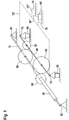
- FIG. 3 is a perspective view for explaining the basic principle of the invention.
- the transmission shown comprises a pedal crankshaft 10, a hollow shaft or output shaft 20 and a sensor shaft 40.
- the pedal crankshaft 10 is held by rotary bearings 30, 32, while the hollow shaft is rotatably supported on the pedal crankshaft 10 with rotary bearings (not shown).
- a drive-side crankshaft drive shaft gear 50 which meshes with a drive-side sensor shaft gear 52, is fastened to the pedal crankshaft 10.
- the drive-side sensor shaft gear 52 like an output-side sensor shaft gear 62, is arranged on the sensor shaft 40.
- the drive-side crankshaft drive shaft gear 50 engages with the drive-side sensor shaft gear 52.
- the output-side sensor shaft gear 62 is arranged on the sensor shaft 40.
- the sensor shaft gear 62 is in engagement with a hollow shaft gear 60 on the output side, which is arranged on the hollow shaft 20 in a rotationally fixed manner.
- the hollow shaft 20 is rotatably and concentrically arranged on the pedal crankshaft 10.
- the output shaft ie hollow shaft 20
- the arrangement shown has the advantage of a continuous pedal crankshaft 10, which extends from crank to crank and also supports the hollow shaft 20.
- a first gear ratio between the shaft gears 50 and 52 is greater than 1 and a second gear ratio between the shaft gears 62 and 60 is also greater than 1.
- the shaft gears 50-62 provide a total gear ratio of greater than 1, although this is generally not necessarily the case is. Rather, the wheels 50 and 62 or 60 and 52 can generally have different sizes and thereby represent different individual and overall gear ratios.
- the wheels 52 and 62 preferably have different effective diameters.
- the sensor shaft 40 is connected to rotary bearings 70, 72 which are supported with respect to the pedal crankshaft 10.
- the pivot bearing 70 is connected via a force sensor 80 to a surface 90 that supports it.
- the pivot bearing 72 is connected to a surface 90 supporting it via a further force sensor 82.
- the surface 90 is part of the gear housing.
- the force sensors 80, 82 can also be supported in bores or other elements of the transmission housing.
- only one of the pivot bearings can be connected to a surface supporting it via a force sensor, while the other pivot bearing can be connected directly, i. H. without a force sensor.
- FIG. 70 ' An alternative storage is shown in dashed lines with frame 70 '.
- the frame 70 ′ is connected to the sensor shaft 40 via pivot bearings 70, 72.
- the frame 70 ' is supported via a force sensor 80' and a connection 76 leading to the force sensor 80 ', the bearing point belonging to the support being arranged radially offset from the sensor shaft 40.
- the connection 76 is non-rotatably connected to the force sensor 80 '.
- the frame 70 ' is not supported on the side of the crank.
- connection 72 ′′ is provided at a bearing point that is radially offset from the sensor shaft 40, which connects the frame 70 'connects to a rotary bearing 74.
- a force sensor 80 ′′ is arranged between the connection 72 ′′ and a support which is again part of the gear housing 90. The force sensor 80 ′′ detects the force that is generated when the connection 72 ′′ rotates around the rotary bearing 74.
- the frame 70 ' is not supported on the side of the crank, but rather the frame 70' is mounted in the pivot bearing 74.
- two or more pivot bearings 74 can also be positioned at different locations on the frame 70'. to be available.
- pivot bearing 74 instead of a pivot bearing 74, one can generally speak of a pivot bearing.
- the frame 70 engages around both sensor gears 50, 52 or 60, 62, but can also encompass only one sensor gear, the other sensor gear being arranged axially offset to the frame. Furthermore, the frame can only support the sensor shaft laterally and, for example, be designed as a cantilever arm from which the sensor shaft extends in the radial direction, the cantilever arm supporting the sensor shaft laterally and rotatably.
- the Figure 2 shows a first embodiment of the transmission according to the invention, with cranks 100, crankshaft 110, which is rotatably supported by bearings 130, 132 in order to be able to rotate according to arrow 112.
- the drive-side crankshaft gear 150 and the output-side hollow shaft gear 160 are rotatably disposed on the crankshaft 110.
- the sensor shaft 140 has a drive-side sensor shaft gear 152 and an output-side sensor shaft gear 162, which mesh with the gears 150 and 160, respectively.
- the frame has a U-shaped extension, the two opposite legs having the pivot bearings 170 ', 172'.
- the sensor shaft is rotatably mounted in a frame 170 by pivot bearings 170 ', 172'.
- the force is measured by a force sensor, not shown, via which the frame 170 is mounted.
- the output-side sensor gear is formed by the wheels 160, 162, and the drive-side sensor gear is formed by the wheels 150, 152.
- the reciprocal of the transmission ratio of the output-side sensor transmission differs from the transmission ratio of the drive-side sensor transmission, whereby a (selectable) overall transmission between the crankshaft 110 and output shaft 120 (designed as a hollow shaft) results.
- the frame encompasses both sensor gears.
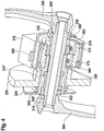
- the Figure 3 shows a second embodiment of the transmission according to the invention, with a pedal crankshaft or crankshaft 210, at the ends of which fastening elements 200 for pedal cranks are provided.
- a hollow shaft 220 is rotatably mounted on the crankshaft 210 via pivot bearings 222 and 222 '.
- the crankshaft is supported on one side by a rotary bearing 230 and on the other side by a rotary bearing 232 located on the hollow shaft, the crankshaft being supported via the rotary bearing 222 between the hollow shaft 220 and the crankshaft 210.
- the Hollow shaft 220 has a radially extending bead 224 at one end, which provides fastening elements (not shown) for the output.
- a frame 270 which carries a sensor shaft 240 via rotary bearings 271, 272, is fastened to the pedal crank via pivot bearings 275 and 275 '.
- a first wheel 252 (drive-side sensor shaft wheel) and a second wheel 262 (output-side sensor shaft wheel) are attached to sensor shaft 240, with only one of the wheels (wheel 252) being surrounded by the frame and the other wheel 262 being located next to the frame, with the sensor shaft also extends laterally (ie axially) from the frame 270 for rotatably supporting the other wheel 262.
- the first wheel 252 of the sensor shaft 240 is in engagement with a drive-side crankshaft drive shaft wheel 250 which is connected in a rotationally fixed manner to the pedal crankshaft 210.
- the second wheel 262 which is located outside the frame, is in engagement with a toothing 260 of the hollow shaft.
- the toothing 260 of the hollow shaft 220 forms a gear, the toothing being arranged in the outer surface of the hollow shaft. This results in a saving of elements and a small diameter for the toothing 260, which can be viewed as a hollow shaft gear on the output side that is formed in one piece with the hollow shaft 260.
- a driven wheel (i.e., a sprocket for connection to the bicycle wheel) 224 is rotatably mounted on the hollow shaft 220.
- an output element in the form of a gear 226 is arranged on the hollow shaft 220, via which an additional torque of a motor can be applied to the hollow shaft 220.
- the frame has a sensor frame bearing 273 on which a force occurs which reflects the transmitted torque.
- the sensor frame bearing 273 is designed as a fastening element at one end of the sensor frame 270, which is remote from the crankshaft.
- a force sensor (not shown) is connected to the sensor frame bearing 273.
- Sensor frame bearing 273 corresponds to the bearings 72 ′′, 76 of the transmission shown in FIG Fig. 1 is shown.
- the sensor frame (shown in dashed lines) encompasses both wheels 262, 252, which are arranged on the sensor shaft 240 ', the sensor shaft 240' being rotatably supported by pivot bearings 272 'and 272 "which are provided in the frame.
- the sensor shaft 240 ' is longer than the sensor shaft and extends from one side of the frame to the other side of the frame.
- the frame comprises fulcrum elements 280' which are arranged on both axial sides of the frame on one side of the frame which is located radially away from the crankshaft is.
- the pivot elements 280 ' are formed in one piece with the frame.
- the fulcrum elements 280 ' are cylindrical (the height being in the order of magnitude of the radius) and are rotatably mounted in a housing which also directly or indirectly supports the pedal crankshaft (and the hollow shaft).
- the storage includes a force sensor that detects a tangential force (related to the crankshaft). If a flexible force sensor (with spring deflection) is used, the frame tilts slightly in the direction of rotation which the pivot point elements 280 'specify. This enables compensation without damaging the gearbox.
- the force sensor is fastened to the frame at a point which is offset radially (in relation to the axis of rotation which the pivot point elements 280 'specify) to the pivot point elements 280'.
- a torque sensor can also be used as the force sensor, which supports the pivot point elements 280 'in a rotationally fixed manner.
- the frame is spaced from the gear 226 to allow free rotation of the gear 226 and to allow a slight tilting movement of the frame around the shaft 210 that corresponds to the spring stroke of a force sensor at different loads.
- the frame can be offset from the gear in the longitudinal direction of the shaft 210 in order to ensure these free movements.
- the Figure 4 shows a third embodiment of the transmission according to the invention, with a pedal crankshaft or crankshaft 310, on which cranks 300 are arranged at fastening points 300 'at both ends of the crankshaft 310.
- a hollow shaft 320 is rotatably mounted on the crankshaft 310 via pivot bearings 322, 322 'which are axially offset from one another.
- the hollow shaft 320 has at one end, which is opposite to the end of the hollow shaft which faces the sensor transmission, a connection option (in the form of a bead 324) for a sprocket 324 for driving a rear wheel of the bicycle.
- an output element in the form of a gear wheel 326 is arranged on the hollow shaft 320, via which an additional torque of a motor can be applied to the hollow shaft 320.
- a rotary bearing 332 supports the hollow shaft 320 (and thus also the crankshaft 310) on one end of the crankshaft 310, and a rotary bearing 330 supports the crankshaft 310 on the opposite end of the crankshaft 310.
- a drive-side crankshaft gear Arranged on the crankshaft 310 is a drive-side crankshaft gear that is permanently connected to it and engages in internal toothing 352, which can be viewed as a drive-side sensor shaft gear.
- the internal toothing 352 is arranged in the inside of a ring gear 390.
- the inside of the ring gear also has internal teeth 362, which can be viewed as a sensor shaft gear on the output side.
- the end of the hollow shaft facing the sensor gear has an external toothing 360, which acts as a hollow shaft gear on the output side, and which meshes with the internal toothing 362.
- the internal toothing 352 is arranged axially offset from the internal toothing 362.
- the internal toothing 352 and the internal toothing 362 have different diameters.
- the radii of the internal toothing and the radii of the external toothing 360 or of the gear wheel 350 can be freely selected within wide limits, as long as different transmission ratios result.
- the loophole is particularly in Figure 4 visible in the upper half of the illustration.
- the internal gears 362 and 352 are connected to one another in a rotationally fixed manner, in particular through a one-piece design with the ring gear 390.
- the ring gear 390 also forms the sensor axis, which is designed here in the sense of a short hollow shaft.
- the ring gear 390 is supported on its outside by pivot bearings 370, 372 that are radially offset from one another, opposite an outer bearing sleeve 376 of the ring gear bearing.
- a frame 378 is provided which surrounds the bearing sleeve and is connected to it in a force-transmitting manner.
- a force sensor 380, 380 ' is arranged on the bearing sleeve, the force sensor 380 being an alternative to the force sensor 380' and vice versa.
- the different transmission ratios generate a force that acts in the radial direction (in relation to the axis of rotation of the pedal crank).
- the force acts perpendicular to the plane in which the contact line of the toothing on the sensor shaft side and the toothing on the crankshaft side (i.e. the toothing of the sensor gear) and the axis of rotation of the crankshaft (and the output shaft) lie.
- the force sensor 380 or 380 'connects (indirectly or directly) an outer carrier (not shown) to the frame 378, the carrier also (indirectly or directly) with the bearings 330, 332 of the crankshaft 310 or the output shaft 320 in a force-transmitting connection is.
- FIG. 5 and in the Figure 6 is the structural design of the variant according to Figure 1 with the force sensor 80 ′′ arranged between the connection 72 and a support 90 and a corresponding modification thereof.
- the frame 70 ' is rotatably mounted in the gear housing 90 with the aid of the pivot bearings 74 and 74'.
- the sensor shaft 40 is also mounted in the frame 70 'via the pivot bearings 70 ".
- the gears (sensor gear) 52, 62 arranged, which in Operationally connected to the gears (sensor gear) 50, 60 located on the crankshaft 10.
- the gears 52 and 62 are connected to one another in a force-transmitting manner.
- the power flow takes place from the crankshaft 10 via the gears 50, 52, 62 and 60 to the output shaft 20.
- the crankshaft 10 is supported by the pivot bearings 30 and 32.
- the force sensor 80 ′′ shown is arranged between the frame 70 'and the gear housing 90 so that it enables the frame 70' to be supported on the gear housing 90 and thus prevents the frame 70 'from rotating about the axis of rotation of the pivot bearings 74, 74' when a force is applied.
- the force sensor 80 ′′ is arranged between the gear housing 90 and the frame 70 ′ in such a way that it detects the relative movement of these two parts in the form of a bend.
- This deflection of the force sensor 80 can be detected with the aid of one or by Hall elements.
- a Wheatstone bridge is mentioned here as an example.
- the arrangement of the force sensor 80" is shown in FIG Figure 5 shown in the area of the pivot bearing of the sensor shaft 40 between frame 70 'and sensor housing 90. This arrangement of the force sensor 80 ′′ would result in a relatively large deflection and thus a very good measurement signal.
- the force sensor 80 ′′ would be as far away as possible from the axis of rotation 69 of the frame 70 ′.
- the sensor signal of the force sensor 80" is now used to regulate or control the electric motor.
- the sensor signal has in the actual sense recorded the torque generated by the driver and is thus used to regulate or control the electric motor.
- FIG. 5 and in the Figure 6 is the structural design of the variant according to Figure 1 with the force sensor 80 ′′ arranged between the connection 72 and a support 90 and a corresponding modification thereof.
- the frame 70 ' is rotatably mounted in the gear housing 90 with the aid of the pivot bearings 74 and 74'.
- the sensor shaft 40 is also mounted in the frame 70 'via the pivot bearings 70 ".
- the gears (sensor gears) 52, 62 are arranged, which are in operative connection with the gears (sensor gears) 50, 60 located on the pedal crankshaft 10.
- the gears 52 and 62 are connected to one another in a force-transmitting manner.
- the power flow takes place from the crankshaft 10 via the gears 50, 52, 62 and 60 to the output shaft 20.
- the crankshaft 10 is supported by the pivot bearings 30 and 32.
- the force sensor 80 ′′ shown is arranged between the frame 70 'and the gear housing 90 so that it enables the frame 70' to be supported on the gear housing 90 and thus prevents the frame 70 'from rotating about the axis of rotation of the pivot bearings 74, 74' when a force is applied.
- the force sensor 80 ′′ is arranged between the gear housing 90 and the frame 70 ′ in such a way that it detects the relative movement of these two parts in the form of a bend.
- This deflection of the force sensor 80 can be detected with the aid of one or by Hall elements.
- a Wheatstone bridge is mentioned here as an example.
- the arrangement of the force sensor 80" is shown in FIG Figure 5 shown in the area of the pivot bearing of the sensor shaft 40 between frame 70 'and sensor housing 90. This arrangement of the force sensor 80 ′′ would result in a relatively large deflection and thus a very good measurement signal.
- the force sensor 80 ′′ would be as far away as possible from the axis of rotation 69 of the frame 70 ′.
- the sensor signal of the force sensor 80" is now used to regulate or control the electric motor.
- the sensor signal has in the actual sense recorded the torque generated by the driver and is thus used to regulate or control the electric motor.
- the frame 70 ′ is firmly connected directly to the gear housing 90. This means that in the Figure 5 or in the Figure 1
- the pivot bearings 74 and 74 'shown are not used or formed here.
- the force sensor 80 ′′ is shown in FIG Figure 6 now arranged directly on the frame 70 'and has no connection to the gear housing 90.
- the force sensor 80 ′′ now measures the so-called internal forces acting on the frame 70 '. Its measurement signals are as well as with the Figure 5 used.
Description
Auf dem Gebiet der Erfindung, d.h. insbesondere das Gebiet der Elektrofahrräder und der zugehörigen Pedalkraftsensoren sind Mechanismen zur Drehmomenterfassung bekannt, um anhand des Drehmoments, mit der die Tretkurbel betätigt wird, auf die Fahrerleistung zu schließen. Die Fahrerleistung bzw. eine damit vergleichbare Größe wird als Eingangsgröße bei der Regelung eines Elektrozusatzantriebs von Elektrofahrrädern verwendet. Die verwendeten Sensoren sind unmittelbar an exponierten Orten vorgesehen und an Elementen befestigt, über die das gesamte Drehmoment übertragen wird. Dadurch sind sie besonders fehleranfällig.In the field of the invention, i.e. in particular the field of electric bicycles and the associated pedal force sensors, mechanisms for torque detection are known in order to infer rider performance from the torque with which the crank is operated. The driver's performance or a variable comparable with it is used as an input variable in the regulation of an additional electric drive for electric bicycles. The sensors used are provided directly in exposed locations and attached to elements through which the entire torque is transmitted. This makes them particularly prone to errors.
Neben Lösungen, bei denen eine Kraft unmittelbar durch Erfassung an der Kurbelwelle ermittelt wird oder durch Kraftsensoren erfasst wird, die an den Pedalen angeordnet sind, bestehen Ansätze, wie sie in
Die
Die
Die
Die
Es ist daher eine Aufgabe der Erfindung, eine einfache Mechanik vorzusehen, um ein Drehmoment zu Erfassen, ohne auf fehleranfällige oder aufwändige Vorkehrungen zurückgreifen zu müssen.It is therefore an object of the invention to provide a simple mechanism to detect a torque without having to resort to error-prone or costly precautions.
Diese Aufgabe wird gelöst durch die Vorrichtung und das Verfahren nach den unabhängigen Ansprüchen.This object is achieved by the device and the method according to the independent claims.
Erfindungsgemäß wird das zu messende Drehmoment der Tretkurbel auf eine parallel zur Tretkurbelachse liegende Sensorachse übertragen. Anschließend wird das Drehmoment wieder zurück auf eine koaxial auf der Tretkurbelwelle drehbar gelagerte Abtriebswelle oder sich in Verlängerung der Tretkurbelwelle erstreckende Abtriebswelle geleitet. Da bei beiden Übertragungen Sensorgetriebe mit unterschiedlichen Übersetzungsverhältnissen verwendet werden, d.h. unterschiedliche Größen der beteiligten Räder, ergibt sich eine Gesamtkraft, die auf die Sensorachse wirkt und die mittels eines Kraftsensors erfasst wird. Die Gesamtkraft ist unmittelbar verknüpft mit den Übersetzungsverhältnissen (die konstant sind) und dem zu messenden Drehmoment. Die Gesamtkraft lässt sich anhand der folgenden Systembetrachtung herleiten: Aufgrund der Energieerhaltung müssen die Drehmomente unterschiedlich sein, die von den beiden Sensorgetrieben übertragen werden, da in gleicher Weise (nur reziprok) die Drehzahlen unterschiedlich sind (die Reibung ist hierbei vernachlässigt). Zwischen Tretkurbelwelle und Sensorwelle ergibt sich also durch dieses Ungleichgewicht eine Gesamtkraft, die in tangentialer Richtung der Drehmomentübertagung (d.h. Tangentialbewegung der Drehelemente der Sensorgetriebe) wirkt. Da die Sensorgetriebe die Drehbewegung an eine Hohlwelle weitergeben, die gemäß der Längserstreckung der Tretkurbelwelle verläuft, kann das erfindungsgemäße Getriebe auf einfache Weise in Systeme eingesetzt werden, bei denen von einer einzigen Tretkurbelwelle ausgegangen wird, die in der gleichen Achse sowohl mit den Tretkurbeln als auch mit einem Abtriebselement (z.B. ein Kettenblatt) vorgesehen ist. Die Erfindung kann somit in einfacher Weise in bekannte Systeme ohne weiteres integriert werden bzw. durch Austausch eingebracht werden.According to the invention, the torque of the pedal crank to be measured is transmitted to a sensor axis lying parallel to the pedal crank axis. The torque is then passed back to a coaxially rotatably mounted output shaft on the crankshaft or an output shaft extending as an extension of the crankshaft. Since sensor gears with different gear ratios are used in both transmissions, i.e. different sizes of the wheels involved, there is a total force that acts on the sensor axis and that is recorded by a force sensor. The total force is directly linked to the gear ratios (which are constant) and the torque to be measured. The total force can be derived from the following system consideration: Due to the conservation of energy, the torques that are transmitted by the two sensor gears must be different, since the speeds are different in the same way (only reciprocally) (the friction is neglected here). This imbalance results in a total force between the crankshaft and the sensor shaft, which acts in the tangential direction of the torque transmission (i.e. tangential movement of the rotary elements of the sensor gear). Since the sensor gears pass on the rotary movement to a hollow shaft, which runs according to the longitudinal extension of the crankshaft, the inventive gear can be used in a simple manner in systems in which a single crankshaft is assumed, which is in the same axis with both the cranks and is provided with an output element (e.g. a chainring). The invention can thus be easily integrated into known systems or introduced by replacement in a simple manner.
Die Abtriebswelle bildet die Welle, von der eine Drehbewegung von der Tretkurbelwelle (angetrieben vom Tretkurbelantrieb) über das Sensorgetriebe übertragen wird, wobei die Abtriebswelle zum Anschluss an einen Abtrieb vorgesehen ist. Diese ist vorzugsweise als Hohlwelle ausgeführt, kann aber auch durch eine beliebige (Voll- oder Hohl-) Welle ausgebildet sein, die sich auf der gleichen Drehachse wie die Tretkurbelwelle erstreckt. Der Begriff Abtriebswelle in dieser Beschreibung wird teilweise als Synonym für Hohlwelle verwendet, da diese Ausprägung die bevorzugte ist, wobei jedoch allgemein für die Abtriebswelle auch andere Wellen verwendet werden können, soweit diese die gleiche Drehachse wie die Abtriebswelle aufweisen.The output shaft forms the shaft from which a rotary movement from the pedal crankshaft (driven by the pedal crank drive) is transmitted via the sensor gear, the output shaft being provided for connection to an output. This is preferably designed as a hollow shaft, but can also be formed by any (solid or hollow) shaft that is on the same axis of rotation as the Pedal crankshaft extends. The term output shaft in this description is partly used as a synonym for hollow shaft, since this variant is the preferred one, although other shafts can generally also be used for the output shaft, provided they have the same axis of rotation as the output shaft.
Die Erfindung betrifft ein Getriebe für Elektrofahrräder zur Erfassung eines Drehmoments, mit dem eine Tretkurbelwelle beaufschlagt ist. Das Getriebe weist auf: die Tretkurbelwelle, auf die das Drehmoment wirkt, und eine zum Anschluss an einen Abtrieb eingerichtete Hohlwelle, durch die sich die Tretkurbelwelle koaxial erstreckt. Diese Erstreckung verhindert Probleme durch einen Radialversatz. Die Hohlwelle ist drehbar zur Tretkurbelwelle gelagert, vorzugsweise durch ein Wälzlager im Inneren der Hohlwelle, die Hohlwelle und Tretkurbelwelle verbindet. Das Getriebe umfasst ferner eine radial zur Tretkurbelwelle versetzte Sensorwelle. Durch diesen Versatz wird eine Kraft an der Antriebseite (und eine Gegenkraft an der Abtriebseite) erzeugt, die auf die Sensorwelle wirkt. Das Getriebe umfasst zudem einen mit der Sensorwelle verbundenen Kraftsensor, der eine von der Sensorwelle ausgeübte Kraft erfasst, die dem zu erfassenden Drehmoment entspricht. Die Verbindung zwischen Sensorwelle und Kraftsensor kann mittelbar sein, beispielsweise durch Befestigen des Kraftsensors an einem Lager der Sensorwelle oder an einem Rahmen, der die Sensorwelle lagert.The invention relates to a transmission for electric bicycles for detecting a torque applied to a pedal crankshaft. The transmission has: the pedal crankshaft, on which the torque acts, and a hollow shaft which is set up for connection to an output and through which the pedal crankshaft extends coaxially. This extension prevents problems caused by radial misalignment. The hollow shaft is rotatably mounted in relation to the pedal crankshaft, preferably by means of a roller bearing inside the hollow shaft, which connects the hollow shaft and the pedal crankshaft. The transmission further comprises a sensor shaft offset radially with respect to the pedal crankshaft. This offset generates a force on the drive side (and a counterforce on the output side) that acts on the sensor shaft. The transmission also includes a force sensor connected to the sensor shaft, which detects a force exerted by the sensor shaft that corresponds to the torque to be detected. The connection between the sensor shaft and the force sensor can be indirect, for example by attaching the force sensor to a bearing of the sensor shaft or to a frame that supports the sensor shaft.
Das Getriebe umfasst ferner ein antriebseitiges Sensorgetriebe und ein abtriebseitiges Sensorgetriebe. Das antriebseitige Sensorgetriebe verbindet die Tretkurbelwelle mit der Sensorwelle und das abtriebseitige Sensorgetriebe verbindet die Sensorwelle mit der Hohlwelle, um eine Drehbewegung zu übertragen. Die Hohlwelle ist eingerichtet mit einem Abtrieb verbunden zu werden, beispielsweise mittels Verbindungsabschnitte an den Enden der Hohlwelle, an die ein Kettenblatt montiert werden kann. Das antriebseitige Sensorgetriebe weist ein Übersetzungsverhältnis auf, das sich von dem Übersetzungsverhältnis des abtriebseitigen Sensorgetriebes unterscheidet. Dadurch sind Kraft und Gegenkraft nicht im Gleichgewicht und es gibt eine Gesamtkraft, die in einem festen Verhältnis zu dem übertragenen Drehmoment (bspw. bezogen auf das Drehmoment an der Tretkurbelwelle) steht. Das Verhältnis ist eine streng monotone, insbesondere lineare bzw. proportionale Abhängigkeit zwischen vom Kraftsensor sensierter Kraft und übertragenem Drehmoment. Der Verhältnisfaktor ist umso größer, je größer der Unterschied zwischen den beiden Übersetzungsverhältnissen der Sensorgetriebe ist.The transmission further comprises a drive-side sensor transmission and an output-side sensor transmission. The drive-side sensor gear connects the crankshaft with the sensor shaft and the output-side sensor gear connects the sensor shaft with the hollow shaft in order to transmit a rotary movement. The hollow shaft is designed to be connected to an output, for example by means of connecting sections at the ends of the hollow shaft to which a chainring can be mounted. The drive-side sensor transmission has a transmission ratio that differs from the transmission ratio of the output-side sensor transmission. As a result, the force and counterforce are not in equilibrium and there is a total force that is in a fixed ratio to the transmitted torque (e.g. based on the torque on the crankshaft). The relationship is a strictly monotonic, in particular linear or proportional dependency between the force sensed by the force sensor and the transmitted torque. The ratio factor is greater, the greater the difference between the two transmission ratios of the sensor gear.
Das erfindungsgemäße Getriebe sieht vor, dass das antriebseitige Sensorgetriebe ein antriebseitiges Tretkurbelwellenrad, das auf der Tretkurbelwelle angeordnet und fest mit dieser verbunden ist, sowie ein antriebseitiges Sensorwellenrad aufweist, das auf der Sensorwelle angeordnet und fest mit dieser verbunden ist. Das antriebseitige Sensorwellenrad und das Tretkurbelwellenrad greifen ineinander, um gemäß einem Zahnradgetriebe eine Drehbewegung von der Tretkurbelwelle an die Sensorwelle zu übertragen. Durch die Übertragung wird die Drehachse der Drehbewegung von der Längsachse Tretkurbelwelle radial nach außen zu der Drehachse der Sensorwelle versetzt. Das abtriebseitige Sensorgetriebe umfasst ein abtriebseitiges Hohlwellenrad, das auf der Hohlwelle angeordnet und mit diesem fest verbunden ist, sowie ein abtriebseitiges Sensorwellenrad, das auf der Sensorwelle angeordnet und fest mit dieser verbunden ist, beziehungsweise direkt mit dem antriebseitigen Sensorwellenrad fest verbunden ist. Das abtriebseitige Sensorwellenrad und das Hohlwellenrad greifen ineinander, um eine Drehbewegung von der Sensorwelle auf die Hohlwelle (d.h. den Abtrieb) zu übertragen.The transmission according to the invention provides that the drive-side sensor transmission has a drive-side pedal crankshaft gear, which is arranged and fixed on the pedal crankshaft is connected to this, and has a drive-side sensor shaft gear, which is arranged on the sensor shaft and firmly connected to it. The drive-side sensor shaft gear and the pedal crankshaft gear mesh with one another in order to transmit a rotary movement from the pedal crankshaft to the sensor shaft in accordance with a gear transmission. As a result of the transmission, the axis of rotation of the rotary movement is offset radially outward from the longitudinal axis of the pedal crankshaft to the axis of rotation of the sensor shaft. The output-side sensor gearbox comprises an output-side hollow shaft gear, which is arranged on the hollow shaft and is firmly connected to it, as well as an output-side sensor shaft gear, which is arranged on the sensor shaft and is firmly connected to it, or is directly connected to the drive-side sensor shaft gear. The output-side sensor shaft gear and the hollow shaft gear mesh with one another in order to transmit a rotary movement from the sensor shaft to the hollow shaft (ie the output).
Das erfindungsgemäße Getriebe umfasst des Weiteren einen Sensorrahmen, in dem die Sensorwelle drehbar gelagert ist. Der Kraftsensor ist einerseits mit dem Sensorrahmen und andererseits mittelbar oder unmittelbar mit einem Gehäuseelement verbunden ist, das die Tretkurbelwelle oder die Hohlwelle zumindest teilweise lagert. Ferner kann der Kraftsensor zwischen Sensorrahmen und einer Fläche vorgesehen sein, die auch mit der Tretkurbelwelle oder der Hohlwelle kraftübertragend verbunden ist. Dadurch kann der Sensor die Kraftdifferenz an dem Rahmen erfassen, die sich durch die unterschiedlichen Übersetzungsverhältnisse ergibt. Zudem ist es durch diese Lagerung möglich, dass ein nachgebender Kraftsensor verwendet wird, dessen Position sich bei unterschiedlichen Kräften ändert (zunehmender Federweg bei zunehmender Kraft), da der Rahmen und die Sensorgetriebe einen Versatz in bestimmten Grenzen zulassen, ohne dass sich die Performance der mechanischen Drehbewegungsübertragung durch das Getriebe ändert.The transmission according to the invention further comprises a sensor frame in which the sensor shaft is rotatably mounted. The force sensor is connected on the one hand to the sensor frame and on the other hand indirectly or directly to a housing element which at least partially supports the pedal crankshaft or the hollow shaft. Furthermore, the force sensor can be provided between the sensor frame and a surface which is also connected in a force-transmitting manner to the pedal crankshaft or the hollow shaft. This enables the sensor to detect the force difference on the frame that results from the different transmission ratios. In addition, this storage makes it possible to use a yielding force sensor, the position of which changes with different forces (increasing spring deflection with increasing force), since the frame and the sensor gear allow an offset within certain limits without affecting the performance of the mechanical Rotational motion transmission changes through the gearbox.
Das Getriebe kann vorsehen, dass das antriebseitige Sensorgetriebe, das abtriebseitige Sensorgetriebe oder beide Sensorgetriebe mindestens ein Getrieberad aufweisen, das als Zahnrad mit Außenverzahnungen ausgebildet sind. Alternativ kann das mindestens eine Getrieberad als Außenverzahnung der Tretkurbelwelle, der Sensorwelle oder der Hohlwelle vorgesehen sein. Weitere Möglichkeiten der Ausbildung sehen vor, dass das mindestens eine Getrieberad als Innenverzahnung der Tretkurbelwelle, der Sensorwelle oder der Hohlwelle ausgebildet ist. Diese Ausbildungen lassen sich kombinieren. Ein Getrieberad ist eingerichtet, eine Drehbewegung von der Tretkurbelwelle auf die Sensorwelle oder von der Sensorwelle auf die Hohlwelle zu übertragen, wobei die Übertragung mittelbar über weitere Radverbindungen vorgesehen sein kann.The transmission can provide that the drive-side sensor transmission, the output-side sensor transmission, or both sensor transmissions have at least one gearwheel which is designed as a gearwheel with external toothing. Alternatively, the at least one gear wheel can be provided as external toothing of the pedal crankshaft, the sensor shaft or the hollow shaft. Further possibilities of the design provide that the at least one gear wheel is designed as internal toothing of the pedal crankshaft, the sensor shaft or the hollow shaft. These trainings can be combined. A gear wheel is set up, a rotary movement from the crankshaft to the sensor shaft or from the sensor shaft to be transmitted to the hollow shaft, it being possible for the transmission to be provided indirectly via further wheel connections.
Insbesondere kann das antriebseitige Sensorgetriebe von einem Paar ineinander greifender Zahnräder mit Außenverzahnung und das abtriebseitige Sensorgetriebe von einem Paar ineinander greifender Zahnräder ausgebildet sein. Das antriebseitige oder das abtriebseitige Sensorgetriebe kann von einem Paar von ineinander greifenden Außenverzahnungen ausgebildet sein. Zumindest eines der beiden Paare sieht eine ineinandergreifende Außenverzahnung vor als eine Verzahnung, die unmittelbar auf einer Außenseite der Tretkurbelwelle, der Sensorwelle oder der Hohlwelle ausgebildet ist. In diese Außenverzahnung greift die Verzahnung eines Zahnrads ein. Alternativ kann das antriebseitige Sensorgetriebe, das abtriebseitige Sensorgetriebe oder beide Sensorgetriebe jeweils von einem Paar Verzahnungen aufweisen. Hierbei ist eine Verzahnung des Paars eine Außenverzahnung eines Zahnrads, eine Außenverzahnung der Tretkurbelwelle, der Sensorwelle oder der Hohlwelle, oder eine Innenverzahnung eines Hohlrad. Die andere Verzahnung des Paars ist eine Außenverzahnung eines Zahnrads, das auf der Tretkurbelwelle, der Sensorwelle oder der Hohlwelle montiert ist, oder ist eine Außenverzahnung der Tretkurbelwelle, der Sensorwelle oder der Hohlwelle selbst. Diese Ausbildungen ermöglichen die Einsparung von Platz und Bauteilen.In particular, the drive-side sensor gear can be formed from a pair of intermeshing gears with external toothing and the output-side sensor gear from a pair of intermeshing gears. The drive-side or the output-side sensor gear can be formed by a pair of intermeshing external gears. At least one of the two pairs provides an interlocking external toothing as a toothing that is formed directly on an outside of the pedal crankshaft, the sensor shaft or the hollow shaft. The teeth of a gear mesh into these external teeth. Alternatively, the drive-side sensor transmission, the output-side sensor transmission or both sensor transmissions can each have a pair of toothings. Here, a toothing of the pair is an external toothing of a gear, an external toothing of the pedal crankshaft, the sensor shaft or the hollow shaft, or an internal toothing of a ring gear. The other toothing of the pair is an external toothing of a gear that is mounted on the pedal crankshaft, the sensor shaft or the hollow shaft, or is an external toothing of the pedal crankshaft, the sensor shaft or the hollow shaft itself. These designs save space and components.
Eine Variante des Getriebes sieht vor, dass das antriebseitige Sensorgetriebe gebildet wird von einem antriebsseitigem Kurbelantriebwellenrad, das auf der Tretkurbelwelle montiert ist, sowie von einer ersten Innenverzahnung eines Hohlrads, das als Hohlwellenstück die Sensorwelle bildet. Das abtriebseitige Sensorgetriebe wird gebildet von einem abtriebsseitigem Hohlwellenrad, das auf der als Abtriebswelle arbeitenden Hohlwelle montiert ist, und einer weiteren Innenverzahnung des Hohlrads, die axial zu der ersten Innenverzahnung versetzt ist. Die Innenverzahnungen sind über das Hohlrad miteinander verbunden. Die Innenverzahnungen weisen unterschiedliche Radien auf, die zu unterschiedlichen Übersetzungsverhältnissen führen. Das Hohlrad ersetzt in dieser Ausführung die Sensorwelle und verbindet die beiden Räder, die sich bei anderen Ausführungsformen der Erfindung gemeinsam auf der Sensorwelle befinden.A variant of the transmission provides that the drive-side sensor transmission is formed by a drive-side crankshaft gear, which is mounted on the crankshaft, and a first internal toothing of a ring gear, which forms the sensor shaft as a hollow shaft piece. The output-side sensor gear is formed by an output-side hollow shaft gear, which is mounted on the hollow shaft working as an output shaft, and a further internal toothing of the ring gear, which is axially offset from the first internal toothing. The internal gears are connected to one another via the ring gear. The internal gears have different radii, which lead to different gear ratios. In this embodiment, the ring gear replaces the sensor shaft and connects the two wheels which, in other embodiments of the invention, are located together on the sensor shaft.
Das Übersetzungsverhältnis des antriebseitigen Sensorgetriebes kann dem Kehrwert des Übersetzungsverhältnisses des abtriebseitigen Sensorgetriebes entsprechen, so dass eine Gesamtübersetzung von 1 erreicht wird.The transmission ratio of the drive-side sensor transmission can correspond to the reciprocal of the transmission ratio of the output-side sensor transmission, so that a total transmission of 1 is achieved.
Der Kraftsensor kann beispielsweise ein Piezoelement oder ein kraftempfindliches Halbleiterelement sein. Ferner kann der Kraftsensor ein Federelement bzw. Verwindungselement und einen zugehöriger Wegmesser bzw. Winkelgeber umfassen, beispielsweise in Form eines Dehnungsmessstreifens, der auf einem elastisch verformbaren Körper angeordnet ist. Der Federweg der Feder kann ferner von einem Wegnehmer erfasst werden, beispielsweise einem Hallelement oder auch ein optischer Sensor, in Verbindung mit Markierungen magnetischer oder optischer Art.The force sensor can be, for example, a piezo element or a force-sensitive semiconductor element. Furthermore, the force sensor can comprise a spring element or torsion element and an associated odometer or angle sensor, for example in the form of a strain gauge, which is arranged on an elastically deformable body. The spring travel of the spring can also be detected by a displacement sensor, for example a Hall element or an optical sensor, in conjunction with markings of a magnetic or optical type.
Die Erfindung wird ferner vorgesehen in einem Verfahren zur Erfassung eines Drehmoments, mit dem eine Tretkurbelwelle beaufschlagt ist. Das Verfahren sieht die folgenden Schritte vor: Übertragen des Drehmoments von der Tretkurbelwelle auf eine Sensorwelle, die parallel zur Tretkurbelwelle versetzt ist, über ein antriebseitiges Sensorgetriebe, und Übertragen eines entsprechenden Drehmoments von der Sensorwelle auf eine mit einem Abtrieb verbundene Hohlwelle, die die gleiche Drehachse wie die Sensorwelle aufweist, über ein abtriebseitiges Sensorgetriebe. Das Übertragen wird über das antriebseitige Sensorgetriebe mit einer Übersetzung vorgesehen, die sich von der Übersetzung des abtriebseitigen Sensorgetriebes unterscheidet. Das Verfahren sieht ferner vor, eine Kraft, die auf die Sensorwelle wirkt, mittels eines Kraftsensors zu erfassen. Der Kraftsensor ist hierbei kraftübertragend mit der Sensorwelle verbunden. Der Betrag der erfassten Kraft gibt die Stärke des Drehmoments wieder.The invention is also provided in a method for detecting a torque with which a pedal crankshaft is applied. The method provides for the following steps: transferring the torque from the crankshaft to a sensor shaft, which is offset parallel to the crankshaft, via a drive-side sensor gear, and transferring a corresponding torque from the sensor shaft to a hollow shaft connected to an output, which has the same axis of rotation as the sensor shaft has, via a sensor gear on the output side. The transmission is provided via the drive-side sensor gear with a gear ratio that differs from the gear ratio of the output-side sensor gear. The method also provides for a force that acts on the sensor shaft to be detected by means of a force sensor. The force sensor is connected to the sensor shaft in a force-transmitting manner. The amount of force recorded reflects the strength of the torque.
Erfindungsgemäß ist die Sensorwelle, welche die Drehbewegung überträgt, in einem Sensorrahmen drehbar gelagert. Die Kraft wird erfindungsgemäß erfasst, indem der Kraftsensor den Sensorrahmen abstützt, um die Kraft zu erfassen, die aufgrund der Sensorwelle auf den Sensorrahmen wirkt.According to the invention, the sensor shaft, which transmits the rotary movement, is rotatably mounted in a sensor frame. According to the invention, the force is detected in that the force sensor supports the sensor frame in order to detect the force that acts on the sensor frame due to the sensor shaft.
Schließlich kann das Verfahren vorsehen, dass das Drehmoment über die Sensorgetriebe übertragen wird durch ineinandergreifende Außenverzahnungen von Zahnrädern oder von Zahnrädern und Außenverzahnungen einer der Wellen. Die Verzahnungen bzw. Zahnräder bilden das Sensorgetriebe. Die Verzahnungen sind Außenverzahnung eines Zahnrads oder einer Außenverzahnung einer der Wellen, die in eine Innenverzahnung eines Hohlrads, das die Sensorwelle vorsieht, eingreifen. Diese Möglichkeiten sind auch kombiniert einsetzbar.Finally, the method can provide that the torque is transmitted via the sensor gears through intermeshing external toothing of gearwheels or of gearwheels and external toothing of one of the shafts. The gears or gears form the sensor gear. The toothing is the external toothing of a gear or an external toothing of one of the shafts, which mesh with an internal toothing of a ring gear provided by the sensor shaft. These options can also be used in combination.
Im Gegensatz zu zahlreichen bekannten Sensoren ermöglicht die Erfindung auch die Umkehrung des Drehsinns des Drehmoments, ohne dass eine Hysterese in der Messung entsteht.In contrast to numerous known sensors, the invention also enables the direction of rotation of the torque to be reversed without creating a hysteresis in the measurement.
Ausführungsbeispiele der Erfindung sind in den Figuren dargestellt und werden in der nachfolgenden Beschreibung näher erläutert.Exemplary embodiments of the invention are shown in the figures and are explained in more detail in the description below.
Es zeigen:
-
Figur 1 eine symbolhaft dargestellte Ausführungsform der Erfindung zur Erläuterung der Grundzüge; -
Figur 2 eine erste Ausgestaltung des erfindungsgemäßen Getriebes, -
Figur 3 eine zweite Ausgestaltung des erfindungsgemäßen Getriebes, -
Figur 4 eine dritte Ausgestaltung des erfindungsgemäßen Getriebes, -
Figur 5 eine vierte Ausgestaltung des erfindungsgemäßen Getriebes
und -
Figur 6 eine Abwandlung der Ausbildung nachFigur 5 .
-
Figure 1 a symbolically illustrated embodiment of the invention to explain the fundamentals; -
Figure 2 a first embodiment of the transmission according to the invention, -
Figure 3 a second embodiment of the transmission according to the invention, -
Figure 4 a third embodiment of the transmission according to the invention, -
Figure 5 a fourth embodiment of the transmission according to the invention
and -
Figure 6 a modification of the trainingFigure 5 .
Die Sensorwelle 40 ist mit Drehlagern 70, 72 verbunden, die gegenüber der Tretkurbelwelle 10 abgestützt ist. Das Drehlager 70 ist über einen Kraftsensor 80 mit einer diesen abstützenden Fläche 90 verbunden. Das Drehlager 72 ist über einen weiteren Kraftsensor 82 mit einer diesen abstützenden Fläche 90 verbunden. Die Fläche 90 ist Teil des Getriebegehäuses. Statt an einer Fläche 90 können sich die Kraftsensoren 80, 82 auch in Bohrungen oder anderen Elementen des Getriebegehäuses abstützen. Alternativ kann nur eines der Drehlager über einen Kraftsensor mit einer diesen abstützenden Fläche verbunden sein, während das andere Drehlager direkt, d. h. ohne Kraftsensor, abgestützt ist.The
Eine alternative Lagerung ist mit Rahmen 70' gestrichelt dargestellt. Der Rahmen 70' ist über Drehlager 70, 72 mit der Sensorwelle 40 verbunden. Der Rahmen 70' ist über einen Kraftsensor 80' und eine zum Kraftsensor 80' führende Verbindung 76 abgestützt, wobei der zur Abstützung gehörende Lagerpunkt radial versetzt zu der Sensorwelle 40 angeordnet ist. Die Verbindung 76 ist drehfest mit dem Kraftsensor 80' verbunden. Bei dieser Ausführungsform ist der Rahmen 70' an der Seite der Tretkurbel nicht abgestützt.An alternative storage is shown in dashed lines with frame 70 '. The
Eine weitere alternative Lagerung, die mit Rahmen 70' ausgeführt ist (d. h. ohne dass eine Verbindung zu den Drehlagern 70, 72 besteht), sieht vor, dass an einem zur Sensorwelle 40 radial versetzten Lagerpunkt eine Verbindung 72" vorgesehen ist, die den Rahmen 70' mit einem Drehlager 74 verbindet. Ein Kraftsensor 80" ist zwischen der Verbindung 72" und einer Abstützung, die wieder Teil des Getriebegehäuses 90 ist, angeordnet. Der Kraftsensor 80" erfasst die Kraft, die sich bei Drehung der Verbindung 72" um das Drehlager 74 ergibt. Hierbei ist der Rahmen 70' an der Seite der Tretkurbel nicht abgestützt, vielmehr ist der Rahmen 70' im Drehlager 74 gelagert. Zur besseren Stabilisierung des Rahmens 70' können auch zwei oder mehrere Drehlager 74 an jeweils unterschiedlichen Stellen des Rahmens 70' vorhanden sein.Another alternative mounting, which is designed with a
Statt eines Drehlagers 74 kann auch allgemein von einer Drehlagerung gesprochen werden.Instead of a pivot bearing 74, one can generally speak of a pivot bearing.
Der Rahmen 70' umgreift beide Sensorgetriebe 50, 52 bzw. 60, 62, kann jedoch auch nur ein Sensorgetriebe umgreifen, wobei das andere Sensorgetriebe axial versetzt zu dem Rahmen angeordnet ist. Ferner kann der Rahmen die Sensorwelle nur seitlich tragen und bspw. als Kragarm ausgebildet sein, von dem sich in radialer Richtung die Sensorwelle weg erstreckt, wobei der Kragarm die Sensorwelle seitlich und drehbar lagert.The frame 70 'engages around both sensor gears 50, 52 or 60, 62, but can also encompass only one sensor gear, the other sensor gear being arranged axially offset to the frame. Furthermore, the frame can only support the sensor shaft laterally and, for example, be designed as a cantilever arm from which the sensor shaft extends in the radial direction, the cantilever arm supporting the sensor shaft laterally and rotatably.
Die
Die
Über Drehlager 275 und 275' ist auf der Tretkurbel ein Rahmen 270 befestigt, der eine Sensorwelle 240 über Drehlager 271, 272 trägt. Auf der Sensorwelle 240 sind ein erstes Rad 252 (antriebseitiges Sensorwellenrad) und ein zweites Rad 262 (abtriebseitiges Sensorwellenrad) befestigt, wobei nur eines der Räder (Rad 252) von dem Rahmen umgeben ist und das andere Rad 262 sich neben dem Rahmen befindet, wobei die Sensorwelle sich auch seitlich (d.h. axial) von dem Rahmen 270 erstreckt, um dort das andere Rad 262 drehbar zu lagern. Das erste Rad 252 der Sensorwelle 240 ist in Eingriff mit einem antriebseitigen Kurbelantriebwellenrad 250, das drehfest mit der Tretkurbelwelle 210 verbunden ist. Das zweite Rad 262, das sich außerhalb des Rahmens befindet, ist in Eingriff mit einer Verzahnung 260 der Hohlwelle. Die Verzahnung 260 der Hohlwelle 220 bildet ein Zahnrad, wobei die Verzahnung in der Außenfläche der Hohlwelle angeordnet ist. Es ergibt sich eine Einsparung an Elementen sowie ein geringer Durchmesser für die Verzahnung 260, die als abtriebseitiges Hohlwellenrad angesehen werden kann, das einteilig mit der Hohlwelle 260 ausgebildet ist. Ein Abtriebrad (d.h. ein Kettenrad zur Verbindung mit dem Laufrad des Fahrrads) 224 ist auf der Hohlwelle 220 drehfest angeordnet. Auf der Hohlwelle 220 ist ferner ein Abtriebelement in Form eines Zahnrades 226 angeordnet über das ein zusätzliches Drehmoment eines Motors auf die Hohlwelle 220 gebracht werden kann.A
Zur Krafterfassung weist der Rahmen ein Sensorrahmenlager 273 auf, an dem eine Kraft auftritt, die das übertragene Drehmoment wiedergibt. Das Sensorrahmenlager 273 ist als Befestigungselement ausgeführt an einem Ende des Sensorrahmens 270, das sich entfernt gelegen zu der Kurbelwelle befindet. Ein Kraftsensor (nicht dargestellt) ist mit dem Sensorrahmenlager 273 verbunden. Sensorrahmenlager 273 entspricht den Lagern 72", 76 des Getriebes, das in
Eine alternative Ausführung des Sensorrahmens ist in
Die
Auf der Kurbelwelle 310 ist ein damit fest verbundenes antriebseitiges Kurbelantriebwellenrad angeordnet, das in eine Innenverzahnung 352 eingreift, die als ein antriebseitiges Sensorwellenrad betrachtet werden kann. Die Innenverzahnung 352 ist in der Innenseite eines Hohlrads 390 angeordnet. Die Innenseite des Hohlrads weist ferner eine Innenverzahnung 362 auf, die als ein abtriebseitiges Sensorwellenrad betrachtet werden kann. Das dem Sensorgetriebe zugewandte Ende der Hohlwelle weist eine Außenverzahnung 360 auf, die als abtriebseitiges Hohlwellenrad wirkt, und die mit der Innenverzahnung 362 in Eingriff ist. Die Innenverzahnung 352 ist axial versetzt zu der Innenverzahnung 362 angeordnet. Die Innenverzahnung 352 und die Innenverzahnung 362 weisen unterschiedliche Durchmesser auf. Die Radien der Innenverzahnungen und die Radien der Außenverzahnung 360 bzw. des Zahnrads 350 sind in weiten Grenzen frei wählbar, solange sich unterschiedliche Übersetzungsverhältnisse ergeben. Zwischen der Innenseite der Hohlwelle 320 und der Außenseite der Tretkurbel ist eine durchgehende Lücke, insbesondere in der Höhe der Außenverzahnung 360, die eine Drehung gegenüber der Tretkurbelwelle 310 ermöglicht. Die Lücke ist insbesondere in
Das Hohlrad 390 wird an seiner Außenseite von radial zueinander versetzten Drehlagern 370, 372 gegenüber einer äußeren Lagerhülse 376 des Hohlradlagers gelagert. Auf der Außenseite der Lagerhülse 376 ist ein Rahmen 378 vorgesehen, der die Lagerhülse umgibt und kraftübertragen mit dieser verbunden ist. Auf der Lagerhülse ist ein Kraftsensor 380, 380' angeordnet, wobei der Kraftsensor 380 eine Alternative zu Kraftsensor 380' ist und umgekehrt. Durch die unterschiedlichen Übertragungsverhältnisse wird eine Kraft erzeugt, die in radialer Richtung (bezogen auf die Drehachse der Tretkurbel) wirkt. Die Kraft wirkt senkrecht zu der Ebene, in der die Kontaktlinie der sensorwellenseitigen Verzahnungen und der kurbelwellenseitigen Verzahnungen (d.h. die Verzahnung des Sensorgetriebes) sowie die Drehachse der Kurbelwelle (und der Abtriebswelle) liegt. Der Kraftsensor 380 oder 380' verbindet (mittelbar oder unmittelbar) einen äußeren Träger (nicht dargestellt) mit dem Rahmen 378, wobei der Träger ebenso (mittelbar oder unmittelbar) mit den Lagern 330, 332 der Kurbelwelle 310 bzw. der Abtriebswelle 320 in kraftübertragender Verbindung ist.The
In der
In der
Die Bezugszeichen der unterschiedlichen Figuren, welche sich bis auf die erste Stelle (über dreistellige Bezugszeichen) gleichen, betreffen die gleichen Merkmale und Komponenten, wobei die in der Beschreibung dargelegten Eigenschaften für alle Komponenten gelten, die mit Bezugszeichen gekennzeichnet sind, die sich gleichen.The reference symbols in the different figures, which are the same except for the first digit (via three-digit reference symbols), relate to the same features and components, the properties set out in the description apply to all components identified with identical reference symbols.
Claims (9)
- Transmission for electric bicycles for detecting a torque which is applied to a pedal crankshaft, wherein the transmission has: the pedal crankshaft on which the torque acts, an output shaft (20) which is designed for connection to an output, a sensor shaft (40) which is offset parallel to the pedal crankshaft (10), and a force sensor (80, 82, 80', 80'') which is connected to the sensor shaft (40) and senses a force which is applied by the sensor shaft (40) and corresponds to the torque to be sensed, wherein the transmission also comprises a drive-side sensor transmission (50, 52) and an output-side sensor transmission (60, 62), the drive-side sensor transmission (50, 52) connects the pedal crankshaft (10) to the sensor shaft (40), and the output-side sensor transmission (60, 62) connects the sensor shaft (40) to the output shaft (20), the output shaft (20) is configured to be connected to an output, and the drive-side sensor transmission (50, 52) has a transmission ratio which differs from the transmission ratio of the output-side sensor transmission (60, 62),
and
the drive-side sensor transmission has a drive-side pedal crankshaft gear (50) which is arranged on the pedal crankshaft (10) and is securely connected thereto, and a drive-side sensor shaft gear (52) which is arranged on the sensor shaft (40) and is securely connected thereto, wherein the drive-side sensor shaft gear (52) and the pedal crank shaft gear (50) engage one in the other, and the output-side sensor transmission comprises an output-side hollow shaft gear (60), which is arranged on the output shaft or hollow shaft (20) and is securely connected thereto, and an output-side sensor shaft gear (62) which is arranged on the sensor shaft (40) and is securely connected thereto, wherein the output-side sensor shaft gear (62) and the hollow shaft gear (60) engage one in the other, characterized in that the transmission comprises a sensor frame (70') which is mounted using a mount (74, 74') in the housing (90) of the transmission, and wherein the sensor shaft (40) is rotatably mounted in the sensor frame (70'), wherein the force sensor (80") is arranged between the sensor frame (70') and the housing (90) of the transmission in such a way that it senses the tangential force acting on the sensor frame (70') and prevents a rotational movement of the sensor frame (70'). - Transmission according to Claim 1, wherein the output shaft is embodied as a hollow shaft (20) through which the pedal crankshaft (10) extends coaxially and which is mounted rotatably with respect to the pedal crankshaft (10).
- Transmission according to one of the preceding claims, characterized in that the force sensor (80'') is arranged at a distance from the rotational axis of the sensor frame (70').
- Transmission according to one of the preceding claims, wherein the drive-side sensor transmission, the output-side sensor transmission or both sensor transmissions have transmission gears which are formed as a gearwheel with external toothing arrangements, as external toothing arrangements of the pedal crankshaft of the sensor shaft or of the output shaft or hollow shaft, as internal toothing arrangements of the pedal crankshaft of the sensor shaft or of the output shaft or hollow shaft or a combination thereof.
- Transmission according to Claim 4, wherein the drive-side sensor transmission is formed by a pair of gearwheels which engage one in the other, with an external toothing arrangement (150, 152), and the output-side sensor transmission is formed by a pair of gearwheels (160, 162) which engage one in the other and the drive-side or the output-side sensor transmission is formed by a pair of external toothing arrangements which engage one in the other, wherein at least one of the two pairs of external toothing arrangements which engage one in the other comprises a toothing arrangement (260) which is formed directly on an outer side of the pedal crankshaft, of the sensor shaft or of the output shaft or hollow shaft and into which the toothing arrangement of a gear wheel (250) engages, or wherein the drive-side sensor transmission, the output-side sensor transmission or both sensor transmissions are respectively formed by a pair of toothing arrangements, wherein a toothing arrangement of the pair is an external toothing arrangement of a gearwheel (350), an external toothing arrangement (360) of the pedal crankshaft, of the sensor shaft or of the output shaft or hollow shaft, or an internal toothing arrangement (352, 362) of a ring gear (390), and the other toothing arrangement of the pair is an external toothing arrangement of a gearwheel (350) which is mounted on the pedal crankshaft, the sensor shaft or the output shaft or hollow shaft, or is an external toothing arrangement (360) of the pedal crankshaft, of the sensor shaft or of the output shaft or hollow shaft itself.
- Transmission according to Claim 4 or 5, wherein the drive-side sensor transmission is formed via a drive-side crank drive gearwheel (350) which is mounted on the pedal crankshaft (10) and a first internal toothing arrangement (352) of a ring gear (390) which, as a piece of hollow shaft, forms the sensor shaft, and the output-side sensor transmission is formed by an output-side hollow shaft gear (360) which is arranged on the hollow shaft which operates as an output shaft, and a further internal toothing arrangement (362) of the ring gear, which toothing arrangement is offset axially with respect to the first internal toothing arrangement (352), wherein the internal toothing arrangements are connected to one another via the ring gear (390), and the internal toothing arrangements have different radii.
- Transmission according to one of the preceding claims, wherein the transmission ratio of the drive-side sensor transmission corresponds to the reciprocal value of the transmission ratio of the output-side sensor transmission.
- Method for sensing a torque of a transmission according to one of the preceding claims, which transmission is acted on by a pedal crankshaft (10), comprising the steps: transmitting the torque from the pedal crankshaft (10) to a sensor shaft (40) which is offset parallel to the pedal crankshaft (10), via a drive-side sensor transmission (50, 52), transmitting a corresponding torque from the sensor shaft (40) to an output shaft or hollow shaft (20) which is connected to an output and which has the same rotational axis as the pedal crankshaft (10), via an output-side sensor transmission (60, 62), wherein the transmission is provided, via the drive-side sensor transmission, with a transmission ratio which differs from the transmission ratio of the output-side sensor transmission, wherein the method also provides sensing a force acting on the sensor shaft (40), by means of the force sensor (70, 72, 80', 80") which is connected in a force-transmitting fashion to the sensor shaft (40), wherein the absolute value of the sensed force represents the magnitude of the torque, wherein the sensor shaft (40) is rotatably mounted in a sensor frame (70'), and the force is sensed by the force sensor supporting the sensor frame (70'), in order to sense the force which acts on the sensor frame (70') through the sensor shaft (40).
- Method according to Claim 8, wherein the torque is transmitted via the sensor transmissions, through external toothing arrangements, engaging one in the other, of gearwheels (50-62) or of gearwheels and external toothing arrangements (260; 360) of one of the shafts, wherein the toothing arrangements and/or gearwheels form the sensor transmission, through an external toothing arrangement of a gearwheel (50-62) or of an external toothing arrangement of one of the shafts into an internal toothing arrangement (352, 362) of a ring gear which the sensor shaft provides, or a combination thereof.
Applications Claiming Priority (2)
| Application Number | Priority Date | Filing Date | Title |
|---|---|---|---|
| DE102010028643A DE102010028643A1 (en) | 2010-05-06 | 2010-05-06 | Electric bicycle transmission for detecting torque and associated method for electric bicycles for detecting torque |
| PCT/EP2011/056661 WO2011138202A1 (en) | 2010-05-06 | 2011-04-27 | Transmission for electrical bicycles for detecting a torque and related method for electrical bicycles for detecting a torque |
Publications (2)
| Publication Number | Publication Date |
|---|---|
| EP2566749A1 EP2566749A1 (en) | 2013-03-13 |
| EP2566749B1 true EP2566749B1 (en) | 2021-04-21 |
Family
ID=44278983
Family Applications (1)
| Application Number | Title | Priority Date | Filing Date |
|---|---|---|---|
| EP11718002.6A Active EP2566749B1 (en) | 2010-05-06 | 2011-04-27 | Transmission for electrical bicycles for detecting a torque and related method for electrical bicycles for detecting a torque |
Country Status (6)
| Country | Link |
|---|---|
| US (1) | US8939247B2 (en) |
| EP (1) | EP2566749B1 (en) |
| JP (2) | JP5837052B2 (en) |
| DE (1) | DE102010028643A1 (en) |
| ES (1) | ES2874812T3 (en) |
| WO (1) | WO2011138202A1 (en) |
Families Citing this family (5)
| Publication number | Priority date | Publication date | Assignee | Title |
|---|---|---|---|---|
| DE102012200232A1 (en) | 2012-01-10 | 2013-07-11 | Robert Bosch Gmbh | Drive device for an electric bicycle with force measurement for driver request detection |
| DE102013220871A1 (en) * | 2013-10-15 | 2015-04-16 | Continental Automotive Gmbh | Method of measuring the torque and e-bike applied by a rider to the pedals of an e-bike |
| US9966785B2 (en) * | 2015-07-10 | 2018-05-08 | Shimano Inc. | Bicycle control system |
| DE102015213902A1 (en) | 2015-07-23 | 2017-01-26 | Robert Bosch Gmbh | Measuring arrangement for measuring the torque on a shaft, crank mechanism and vehicle |
| DE102016201455B3 (en) * | 2016-02-01 | 2017-06-01 | Schaeffler Technologies AG & Co. KG | Measuring device and method for determining operating parameters on shafts |
Citations (3)
| Publication number | Priority date | Publication date | Assignee | Title |
|---|---|---|---|---|
| JPS5737230A (en) * | 1980-08-18 | 1982-03-01 | Ono Sokki Co Ltd | Torque detector |
| US20020166708A1 (en) * | 2001-05-10 | 2002-11-14 | Merida Industry Co., Ltd. | Transmission for an electric bicycle |
| JP2002331985A (en) * | 2001-05-31 | 2002-11-19 | Ind Technol Res Inst | Torque detection and large gear miniaturization device for bicycle |
Family Cites Families (14)
| Publication number | Priority date | Publication date | Assignee | Title |
|---|---|---|---|---|
| JPS533840B2 (en) * | 1973-12-17 | 1978-02-10 | ||
| JPS533840A (en) | 1976-06-30 | 1978-01-13 | Nec Corp | Infrared ray dark field observation device |
| JPS5563730A (en) * | 1978-11-06 | 1980-05-14 | Kataue Shiro | Method of measuring rotation torque and its device |
| JPH07253318A (en) * | 1994-03-15 | 1995-10-03 | Secoh Giken Inc | Rotation detector |
| JP3417147B2 (en) * | 1995-06-14 | 2003-06-16 | セイコーエプソン株式会社 | Driving force assist device |
| JPH10194186A (en) * | 1997-01-13 | 1998-07-28 | Yamaha Motor Co Ltd | Motor-assisted bicycle |
| JP3954693B2 (en) | 1997-07-14 | 2007-08-08 | 本田技研工業株式会社 | Input torque detection device for an electric auxiliary vehicle |
| JPH1144588A (en) * | 1997-07-29 | 1999-02-16 | Tec Corp | Torque detector |
| JP2000079895A (en) * | 1998-06-23 | 2000-03-21 | Yamaha Motor Co Ltd | Motor-assisted vehicle |
| JP2000153795A (en) * | 1998-06-29 | 2000-06-06 | Yamaha Motor Co Ltd | Electrically assisted vehicle |
| JP2000142545A (en) * | 1998-11-12 | 2000-05-23 | Honda Motor Co Ltd | Motor-assisted vehicle |
| TW480234B (en) * | 1999-10-13 | 2002-03-21 | Honda Motor Co Ltd | Motor-driven assist unit |
| US6595072B2 (en) * | 2001-10-22 | 2003-07-22 | Gordon Liao | Sensor of the pedaling force of a power-assisting bike |
| JP2008189136A (en) * | 2007-02-05 | 2008-08-21 | Bridgestone Corp | Electric auxiliary device for power assisted bicycle, and power assisted bicycle |
-
2010
- 2010-05-06 DE DE102010028643A patent/DE102010028643A1/en not_active Withdrawn
-
2011
- 2011-04-27 ES ES11718002T patent/ES2874812T3/en active Active
- 2011-04-27 US US13/696,524 patent/US8939247B2/en not_active Expired - Fee Related
- 2011-04-27 WO PCT/EP2011/056661 patent/WO2011138202A1/en active Application Filing
- 2011-04-27 EP EP11718002.6A patent/EP2566749B1/en active Active
- 2011-04-27 JP JP2013508435A patent/JP5837052B2/en not_active Expired - Fee Related
-
2014
- 2014-06-24 JP JP2014129227A patent/JP5865957B2/en active Active
Patent Citations (3)
| Publication number | Priority date | Publication date | Assignee | Title |
|---|---|---|---|---|
| JPS5737230A (en) * | 1980-08-18 | 1982-03-01 | Ono Sokki Co Ltd | Torque detector |
| US20020166708A1 (en) * | 2001-05-10 | 2002-11-14 | Merida Industry Co., Ltd. | Transmission for an electric bicycle |
| JP2002331985A (en) * | 2001-05-31 | 2002-11-19 | Ind Technol Res Inst | Torque detection and large gear miniaturization device for bicycle |
Also Published As
| Publication number | Publication date |
|---|---|
| DE102010028643A1 (en) | 2011-11-10 |
| JP5865957B2 (en) | 2016-02-17 |
| CN102883946A (en) | 2013-01-16 |
| US20130112038A1 (en) | 2013-05-09 |
| EP2566749A1 (en) | 2013-03-13 |
| JP2014169082A (en) | 2014-09-18 |
| ES2874812T3 (en) | 2021-11-05 |
| WO2011138202A1 (en) | 2011-11-10 |
| JP5837052B2 (en) | 2015-12-24 |
| US8939247B2 (en) | 2015-01-27 |
| JP2013530862A (en) | 2013-08-01 |
Similar Documents
| Publication | Publication Date | Title |
|---|---|---|
| EP3247619B1 (en) | Drive assembly for a manually driven vehicle with an electric auxiliary drive, method for regulating a drive assembly of this type, and use | |
| EP2566749B1 (en) | Transmission for electrical bicycles for detecting a torque and related method for electrical bicycles for detecting a torque | |
| EP2748573B1 (en) | Bottom bracket | |
| DE102011120675B4 (en) | Gear unit | |
| EP2457753B1 (en) | Actuator | |
| EP3323701B1 (en) | Device for detecting torque, in particular for controlling the additional drive of a vehicle which can be moved by human strength | |
| DE102008008835A1 (en) | Device for determining a torque | |
| EP2615022B1 (en) | Drive device for an electric bicycle with force measurement for detection of the rider's intentions | |
| EP1979209A1 (en) | Actuator, particularly for a motor vehicle parking brake | |
| EP2483142A1 (en) | Three-chain transmission for a vehicle having an electric motor | |
| WO2011023366A1 (en) | Drive unit | |
| DE202010008467U1 (en) | Detachable actuator, in particular with electromechanical drive | |
| DE102017202507A1 (en) | Torque detecting device, drive and working device | |
| DE102007058657A1 (en) | Device for measuring a torsional moment and arrangement, comprising a rotating shaft and a device for measuring a torsional moment | |
| DE102019107644A1 (en) | E-axis actuator with bearing of the pinion on the housing and an electric motor actuated axle drive | |
| DE102011053277A1 (en) | Stabilizer for compensating movements of motor car, has measuring arrangement arranged between driven shafts and stabilizer parts and designed as rotational torque sensor for acquisition of torsion between driven shafts and stabilizer parts | |
| DE102010023355A1 (en) | Arrangement for measuring rotational torque applied by rider of pedelec for propulsion of pedelec, has Hall-sensors detecting ends that exhibit respective distances to axis, where one of distances differs from other distance | |
| EP2386844B1 (en) | Torque sensor | |
| DE102008021591A1 (en) | Electro mechanical steering has steering rod with toothing section, and input shaft is provided with steering gear, which cogs with toothing section of steering rod | |
| DE102017011599A1 (en) | A threaded spindle structure and assembly and rear wheel steering apparatus using the same | |
| EP1312534B1 (en) | Steering wheel steering angle determination apparatus | |
| EP3626593B1 (en) | Compact bottom bracket assembly with torque measuring sleeve | |
| EP3450200B1 (en) | Wheel hub transmission unit for a wheel hub of a vehicle, wheel hub and vehicle with auxiliary drive | |
| EP3611088B1 (en) | Crank and bicycle comprising same | |
| DE102011087784A1 (en) | Crank gear structure for electrical bicycle, has crank shaft assembly that is provided between transmitter wheels in torsion-labile manner so that rotational angle difference is formed at transmitter wheels |
Legal Events
| Date | Code | Title | Description |
|---|---|---|---|
| PUAI | Public reference made under article 153(3) epc to a published international application that has entered the european phase |
Free format text: ORIGINAL CODE: 0009012 |
|
| 17P | Request for examination filed |
Effective date: 20121206 |
|
| AK | Designated contracting states |
Kind code of ref document: A1 Designated state(s): AL AT BE BG CH CY CZ DE DK EE ES FI FR GB GR HR HU IE IS IT LI LT LU LV MC MK MT NL NO PL PT RO RS SE SI SK SM TR |
|
| DAX | Request for extension of the european patent (deleted) | ||
| 17Q | First examination report despatched |
Effective date: 20160622 |
|
| STAA | Information on the status of an ep patent application or granted ep patent |
Free format text: STATUS: EXAMINATION IS IN PROGRESS |
|
| RAP1 | Party data changed (applicant data changed or rights of an application transferred) |
Owner name: ROBERT BOSCH GMBH |
|
| GRAP | Despatch of communication of intention to grant a patent |
Free format text: ORIGINAL CODE: EPIDOSNIGR1 |
|
| STAA | Information on the status of an ep patent application or granted ep patent |
Free format text: STATUS: GRANT OF PATENT IS INTENDED |
|
| INTG | Intention to grant announced |
Effective date: 20210129 |
|
| GRAS | Grant fee paid |
Free format text: ORIGINAL CODE: EPIDOSNIGR3 |
|
| GRAA | (expected) grant |
Free format text: ORIGINAL CODE: 0009210 |
|
| STAA | Information on the status of an ep patent application or granted ep patent |
Free format text: STATUS: THE PATENT HAS BEEN GRANTED |
|
| AK | Designated contracting states |
Kind code of ref document: B1 Designated state(s): AL AT BE BG CH CY CZ DE DK EE ES FI FR GB GR HR HU IE IS IT LI LT LU LV MC MK MT NL NO PL PT RO RS SE SI SK SM TR |
|
| REG | Reference to a national code |
Ref country code: GB Ref legal event code: FG4D Free format text: NOT ENGLISH |
|
| REG | Reference to a national code |
Ref country code: NL Ref legal event code: FP |
|
| REG | Reference to a national code |
Ref country code: CH Ref legal event code: EP |
|
| REG | Reference to a national code |
Ref country code: DE Ref legal event code: R096 Ref document number: 502011017113 Country of ref document: DE Ref country code: IE Ref legal event code: FG4D Free format text: LANGUAGE OF EP DOCUMENT: GERMAN |
|
| REG | Reference to a national code |
Ref country code: AT Ref legal event code: REF Ref document number: 1384363 Country of ref document: AT Kind code of ref document: T Effective date: 20210515 |
|
| REG | Reference to a national code |
Ref country code: LT Ref legal event code: MG9D |
|
| PGFP | Annual fee paid to national office [announced via postgrant information from national office to epo] |
Ref country code: CH Payment date: 20210602 Year of fee payment: 11 Ref country code: ES Payment date: 20210506 Year of fee payment: 11 |
|
| PG25 | Lapsed in a contracting state [announced via postgrant information from national office to epo] |
Ref country code: HR Free format text: LAPSE BECAUSE OF FAILURE TO SUBMIT A TRANSLATION OF THE DESCRIPTION OR TO PAY THE FEE WITHIN THE PRESCRIBED TIME-LIMIT Effective date: 20210421 Ref country code: BG Free format text: LAPSE BECAUSE OF FAILURE TO SUBMIT A TRANSLATION OF THE DESCRIPTION OR TO PAY THE FEE WITHIN THE PRESCRIBED TIME-LIMIT Effective date: 20210721 Ref country code: LT Free format text: LAPSE BECAUSE OF FAILURE TO SUBMIT A TRANSLATION OF THE DESCRIPTION OR TO PAY THE FEE WITHIN THE PRESCRIBED TIME-LIMIT Effective date: 20210421 Ref country code: FI Free format text: LAPSE BECAUSE OF FAILURE TO SUBMIT A TRANSLATION OF THE DESCRIPTION OR TO PAY THE FEE WITHIN THE PRESCRIBED TIME-LIMIT Effective date: 20210421 |
|
| PGFP | Annual fee paid to national office [announced via postgrant information from national office to epo] |
Ref country code: NL Payment date: 20210430 Year of fee payment: 11 |
|
| REG | Reference to a national code |
Ref country code: ES Ref legal event code: FG2A Ref document number: 2874812 Country of ref document: ES Kind code of ref document: T3 Effective date: 20211105 |
|
| PG25 | Lapsed in a contracting state [announced via postgrant information from national office to epo] |
Ref country code: SE Free format text: LAPSE BECAUSE OF FAILURE TO SUBMIT A TRANSLATION OF THE DESCRIPTION OR TO PAY THE FEE WITHIN THE PRESCRIBED TIME-LIMIT Effective date: 20210421 Ref country code: RS Free format text: LAPSE BECAUSE OF FAILURE TO SUBMIT A TRANSLATION OF THE DESCRIPTION OR TO PAY THE FEE WITHIN THE PRESCRIBED TIME-LIMIT Effective date: 20210421 Ref country code: IS Free format text: LAPSE BECAUSE OF FAILURE TO SUBMIT A TRANSLATION OF THE DESCRIPTION OR TO PAY THE FEE WITHIN THE PRESCRIBED TIME-LIMIT Effective date: 20210821 Ref country code: LV Free format text: LAPSE BECAUSE OF FAILURE TO SUBMIT A TRANSLATION OF THE DESCRIPTION OR TO PAY THE FEE WITHIN THE PRESCRIBED TIME-LIMIT Effective date: 20210421 Ref country code: GR Free format text: LAPSE BECAUSE OF FAILURE TO SUBMIT A TRANSLATION OF THE DESCRIPTION OR TO PAY THE FEE WITHIN THE PRESCRIBED TIME-LIMIT Effective date: 20210722 Ref country code: PL Free format text: LAPSE BECAUSE OF FAILURE TO SUBMIT A TRANSLATION OF THE DESCRIPTION OR TO PAY THE FEE WITHIN THE PRESCRIBED TIME-LIMIT Effective date: 20210421 Ref country code: PT Free format text: LAPSE BECAUSE OF FAILURE TO SUBMIT A TRANSLATION OF THE DESCRIPTION OR TO PAY THE FEE WITHIN THE PRESCRIBED TIME-LIMIT Effective date: 20210823 Ref country code: NO Free format text: LAPSE BECAUSE OF FAILURE TO SUBMIT A TRANSLATION OF THE DESCRIPTION OR TO PAY THE FEE WITHIN THE PRESCRIBED TIME-LIMIT Effective date: 20210721 |
|
| PG25 | Lapsed in a contracting state [announced via postgrant information from national office to epo] |
Ref country code: LU Free format text: LAPSE BECAUSE OF NON-PAYMENT OF DUE FEES Effective date: 20210427 |
|
| REG | Reference to a national code |
Ref country code: BE Ref legal event code: MM Effective date: 20210430 |
|
| REG | Reference to a national code |
Ref country code: DE Ref legal event code: R097 Ref document number: 502011017113 Country of ref document: DE |
|
| PG25 | Lapsed in a contracting state [announced via postgrant information from national office to epo] |
Ref country code: MC Free format text: LAPSE BECAUSE OF FAILURE TO SUBMIT A TRANSLATION OF THE DESCRIPTION OR TO PAY THE FEE WITHIN THE PRESCRIBED TIME-LIMIT Effective date: 20210421 Ref country code: RO Free format text: LAPSE BECAUSE OF FAILURE TO SUBMIT A TRANSLATION OF THE DESCRIPTION OR TO PAY THE FEE WITHIN THE PRESCRIBED TIME-LIMIT Effective date: 20210421 Ref country code: DK Free format text: LAPSE BECAUSE OF FAILURE TO SUBMIT A TRANSLATION OF THE DESCRIPTION OR TO PAY THE FEE WITHIN THE PRESCRIBED TIME-LIMIT Effective date: 20210421 Ref country code: EE Free format text: LAPSE BECAUSE OF FAILURE TO SUBMIT A TRANSLATION OF THE DESCRIPTION OR TO PAY THE FEE WITHIN THE PRESCRIBED TIME-LIMIT Effective date: 20210421 Ref country code: CZ Free format text: LAPSE BECAUSE OF FAILURE TO SUBMIT A TRANSLATION OF THE DESCRIPTION OR TO PAY THE FEE WITHIN THE PRESCRIBED TIME-LIMIT Effective date: 20210421 Ref country code: SK Free format text: LAPSE BECAUSE OF FAILURE TO SUBMIT A TRANSLATION OF THE DESCRIPTION OR TO PAY THE FEE WITHIN THE PRESCRIBED TIME-LIMIT Effective date: 20210421 Ref country code: SM Free format text: LAPSE BECAUSE OF FAILURE TO SUBMIT A TRANSLATION OF THE DESCRIPTION OR TO PAY THE FEE WITHIN THE PRESCRIBED TIME-LIMIT Effective date: 20210421 |
|
| PLBE | No opposition filed within time limit |
Free format text: ORIGINAL CODE: 0009261 |
|
| STAA | Information on the status of an ep patent application or granted ep patent |
Free format text: STATUS: NO OPPOSITION FILED WITHIN TIME LIMIT |
|
| GBPC | Gb: european patent ceased through non-payment of renewal fee |
Effective date: 20210721 |
|
| 26N | No opposition filed |
Effective date: 20220124 |
|
| PG25 | Lapsed in a contracting state [announced via postgrant information from national office to epo] |
Ref country code: IE Free format text: LAPSE BECAUSE OF NON-PAYMENT OF DUE FEES Effective date: 20210427 Ref country code: GB Free format text: LAPSE BECAUSE OF NON-PAYMENT OF DUE FEES Effective date: 20210721 |
|
| PG25 | Lapsed in a contracting state [announced via postgrant information from national office to epo] |
Ref country code: IS Free format text: LAPSE BECAUSE OF FAILURE TO SUBMIT A TRANSLATION OF THE DESCRIPTION OR TO PAY THE FEE WITHIN THE PRESCRIBED TIME-LIMIT Effective date: 20210821 Ref country code: AL Free format text: LAPSE BECAUSE OF FAILURE TO SUBMIT A TRANSLATION OF THE DESCRIPTION OR TO PAY THE FEE WITHIN THE PRESCRIBED TIME-LIMIT Effective date: 20210421 |
|
| REG | Reference to a national code |
Ref country code: AT Ref legal event code: MM01 Ref document number: 1384363 Country of ref document: AT Kind code of ref document: T Effective date: 20210427 |
|
| PG25 | Lapsed in a contracting state [announced via postgrant information from national office to epo] |
Ref country code: IT Free format text: LAPSE BECAUSE OF FAILURE TO SUBMIT A TRANSLATION OF THE DESCRIPTION OR TO PAY THE FEE WITHIN THE PRESCRIBED TIME-LIMIT Effective date: 20210421 Ref country code: BE Free format text: LAPSE BECAUSE OF NON-PAYMENT OF DUE FEES Effective date: 20210430 |
|
| PG25 | Lapsed in a contracting state [announced via postgrant information from national office to epo] |
Ref country code: AT Free format text: LAPSE BECAUSE OF NON-PAYMENT OF DUE FEES Effective date: 20210427 |
|
| REG | Reference to a national code |
Ref country code: CH Ref legal event code: PL |
|
| REG | Reference to a national code |
Ref country code: NL Ref legal event code: MM Effective date: 20220501 |
|
| PG25 | Lapsed in a contracting state [announced via postgrant information from national office to epo] |
Ref country code: NL Free format text: LAPSE BECAUSE OF NON-PAYMENT OF DUE FEES Effective date: 20220501 Ref country code: LI Free format text: LAPSE BECAUSE OF NON-PAYMENT OF DUE FEES Effective date: 20220430 Ref country code: CH Free format text: LAPSE BECAUSE OF NON-PAYMENT OF DUE FEES Effective date: 20220430 |
|
| PG25 | Lapsed in a contracting state [announced via postgrant information from national office to epo] |
Ref country code: HU Free format text: LAPSE BECAUSE OF FAILURE TO SUBMIT A TRANSLATION OF THE DESCRIPTION OR TO PAY THE FEE WITHIN THE PRESCRIBED TIME-LIMIT; INVALID AB INITIO Effective date: 20110427 Ref country code: CY Free format text: LAPSE BECAUSE OF FAILURE TO SUBMIT A TRANSLATION OF THE DESCRIPTION OR TO PAY THE FEE WITHIN THE PRESCRIBED TIME-LIMIT Effective date: 20210421 |
|
| REG | Reference to a national code |
Ref country code: ES Ref legal event code: FD2A Effective date: 20230605 |
|
| PG25 | Lapsed in a contracting state [announced via postgrant information from national office to epo] |
Ref country code: ES Free format text: LAPSE BECAUSE OF NON-PAYMENT OF DUE FEES Effective date: 20220428 |
|
| PGFP | Annual fee paid to national office [announced via postgrant information from national office to epo] |
Ref country code: FR Payment date: 20230417 Year of fee payment: 13 Ref country code: DE Payment date: 20230627 Year of fee payment: 13 |