EP2566622B1 - Kondensatvermeidungshaube - Google Patents
Kondensatvermeidungshaube Download PDFInfo
- Publication number
- EP2566622B1 EP2566622B1 EP11728770.6A EP11728770A EP2566622B1 EP 2566622 B1 EP2566622 B1 EP 2566622B1 EP 11728770 A EP11728770 A EP 11728770A EP 2566622 B1 EP2566622 B1 EP 2566622B1
- Authority
- EP
- European Patent Office
- Prior art keywords
- peripheral device
- base device
- block
- coupling
- base unit
- Prior art date
- Legal status (The legal status is an assumption and is not a legal conclusion. Google has not performed a legal analysis and makes no representation as to the accuracy of the status listed.)
- Active
Links
- 230000002265 prevention Effects 0.000 title description 5
- 230000002093 peripheral effect Effects 0.000 claims description 133
- 230000008878 coupling Effects 0.000 claims description 90
- 238000010168 coupling process Methods 0.000 claims description 90
- 238000005859 coupling reaction Methods 0.000 claims description 90
- 230000033001 locomotion Effects 0.000 claims description 18
- 238000002156 mixing Methods 0.000 claims description 17
- 230000005291 magnetic effect Effects 0.000 claims description 10
- 239000000126 substance Substances 0.000 claims description 6
- 230000001419 dependent effect Effects 0.000 claims description 4
- 230000005294 ferromagnetic effect Effects 0.000 claims description 4
- 230000000007 visual effect Effects 0.000 claims description 3
- 238000005496 tempering Methods 0.000 description 24
- 238000010438 heat treatment Methods 0.000 description 18
- 230000003287 optical effect Effects 0.000 description 10
- 230000008859 change Effects 0.000 description 9
- 230000001939 inductive effect Effects 0.000 description 9
- 230000002792 vascular Effects 0.000 description 9
- 230000008054 signal transmission Effects 0.000 description 8
- 230000008901 benefit Effects 0.000 description 7
- 239000011888 foil Substances 0.000 description 7
- 230000005540 biological transmission Effects 0.000 description 5
- 229910052751 metal Inorganic materials 0.000 description 5
- 239000002184 metal Substances 0.000 description 5
- 239000004020 conductor Substances 0.000 description 4
- 230000006870 function Effects 0.000 description 4
- 239000007788 liquid Substances 0.000 description 4
- 238000003860 storage Methods 0.000 description 4
- 239000003990 capacitor Substances 0.000 description 3
- 238000009833 condensation Methods 0.000 description 3
- 230000005494 condensation Effects 0.000 description 3
- 230000000694 effects Effects 0.000 description 3
- 229910052782 aluminium Inorganic materials 0.000 description 2
- XAGFODPZIPBFFR-UHFFFAOYSA-N aluminium Chemical compound [Al] XAGFODPZIPBFFR-UHFFFAOYSA-N 0.000 description 2
- 238000000429 assembly Methods 0.000 description 2
- 230000000712 assembly Effects 0.000 description 2
- 150000001875 compounds Chemical class 0.000 description 2
- 238000011109 contamination Methods 0.000 description 2
- 238000001816 cooling Methods 0.000 description 2
- 238000001514 detection method Methods 0.000 description 2
- 239000011521 glass Substances 0.000 description 2
- 238000004519 manufacturing process Methods 0.000 description 2
- 230000007246 mechanism Effects 0.000 description 2
- 150000002739 metals Chemical class 0.000 description 2
- 229910052709 silver Inorganic materials 0.000 description 2
- 239000004332 silver Substances 0.000 description 2
- 239000007787 solid Substances 0.000 description 2
- 239000013585 weight reducing agent Substances 0.000 description 2
- 229910000859 α-Fe Inorganic materials 0.000 description 2
- 230000009471 action Effects 0.000 description 1
- 230000002457 bidirectional effect Effects 0.000 description 1
- 230000015572 biosynthetic process Effects 0.000 description 1
- 239000008280 blood Substances 0.000 description 1
- 210000004369 blood Anatomy 0.000 description 1
- 238000004113 cell culture Methods 0.000 description 1
- 239000000919 ceramic Substances 0.000 description 1
- 238000004140 cleaning Methods 0.000 description 1
- 230000000295 complement effect Effects 0.000 description 1
- 239000002131 composite material Substances 0.000 description 1
- 238000005260 corrosion Methods 0.000 description 1
- 230000007797 corrosion Effects 0.000 description 1
- 239000006185 dispersion Substances 0.000 description 1
- 230000005684 electric field Effects 0.000 description 1
- 238000005516 engineering process Methods 0.000 description 1
- 238000002474 experimental method Methods 0.000 description 1
- 231100001261 hazardous Toxicity 0.000 description 1
- 230000036541 health Effects 0.000 description 1
- 238000009434 installation Methods 0.000 description 1
- 239000011810 insulating material Substances 0.000 description 1
- 230000003993 interaction Effects 0.000 description 1
- 238000002955 isolation Methods 0.000 description 1
- 239000000463 material Substances 0.000 description 1
- 238000000034 method Methods 0.000 description 1
- 239000000203 mixture Substances 0.000 description 1
- 230000005693 optoelectronics Effects 0.000 description 1
- 230000008569 process Effects 0.000 description 1
- 230000009467 reduction Effects 0.000 description 1
- 230000004044 response Effects 0.000 description 1
- 238000000926 separation method Methods 0.000 description 1
- 239000000243 solution Substances 0.000 description 1
- 238000009987 spinning Methods 0.000 description 1
- 239000000725 suspension Substances 0.000 description 1
- 230000001052 transient effect Effects 0.000 description 1
Images


Classifications
-
- B—PERFORMING OPERATIONS; TRANSPORTING
- B01—PHYSICAL OR CHEMICAL PROCESSES OR APPARATUS IN GENERAL
- B01F—MIXING, e.g. DISSOLVING, EMULSIFYING OR DISPERSING
- B01F29/00—Mixers with rotating receptacles
- B01F29/30—Mixing the contents of individual packages or containers, e.g. by rotating tins or bottles
- B01F29/31—Mixing the contents of individual packages or containers, e.g. by rotating tins or bottles the containers being supported by driving means, e.g. by rotating rollers
-
- B—PERFORMING OPERATIONS; TRANSPORTING
- B01—PHYSICAL OR CHEMICAL PROCESSES OR APPARATUS IN GENERAL
- B01L—CHEMICAL OR PHYSICAL LABORATORY APPARATUS FOR GENERAL USE
- B01L7/00—Heating or cooling apparatus; Heat insulating devices
-
- B—PERFORMING OPERATIONS; TRANSPORTING
- B23—MACHINE TOOLS; METAL-WORKING NOT OTHERWISE PROVIDED FOR
- B23P—METAL-WORKING NOT OTHERWISE PROVIDED FOR; COMBINED OPERATIONS; UNIVERSAL MACHINE TOOLS
- B23P19/00—Machines for simply fitting together or separating metal parts or objects, or metal and non-metal parts, whether or not involving some deformation; Tools or devices therefor so far as not provided for in other classes
-
- H—ELECTRICITY
- H05—ELECTRIC TECHNIQUES NOT OTHERWISE PROVIDED FOR
- H05B—ELECTRIC HEATING; ELECTRIC LIGHT SOURCES NOT OTHERWISE PROVIDED FOR; CIRCUIT ARRANGEMENTS FOR ELECTRIC LIGHT SOURCES, IN GENERAL
- H05B6/00—Heating by electric, magnetic or electromagnetic fields
- H05B6/02—Induction heating
- H05B6/06—Control, e.g. of temperature, of power
-
- H—ELECTRICITY
- H05—ELECTRIC TECHNIQUES NOT OTHERWISE PROVIDED FOR
- H05B—ELECTRIC HEATING; ELECTRIC LIGHT SOURCES NOT OTHERWISE PROVIDED FOR; CIRCUIT ARRANGEMENTS FOR ELECTRIC LIGHT SOURCES, IN GENERAL
- H05B6/00—Heating by electric, magnetic or electromagnetic fields
- H05B6/02—Induction heating
- H05B6/10—Induction heating apparatus, other than furnaces, for specific applications
-
- B—PERFORMING OPERATIONS; TRANSPORTING
- B01—PHYSICAL OR CHEMICAL PROCESSES OR APPARATUS IN GENERAL
- B01L—CHEMICAL OR PHYSICAL LABORATORY APPARATUS FOR GENERAL USE
- B01L2300/00—Additional constructional details
- B01L2300/18—Means for temperature control
- B01L2300/1805—Conductive heating, heat from thermostatted solids is conducted to receptacles, e.g. heating plates, blocks
-
- Y—GENERAL TAGGING OF NEW TECHNOLOGICAL DEVELOPMENTS; GENERAL TAGGING OF CROSS-SECTIONAL TECHNOLOGIES SPANNING OVER SEVERAL SECTIONS OF THE IPC; TECHNICAL SUBJECTS COVERED BY FORMER USPC CROSS-REFERENCE ART COLLECTIONS [XRACs] AND DIGESTS
- Y10—TECHNICAL SUBJECTS COVERED BY FORMER USPC
- Y10T—TECHNICAL SUBJECTS COVERED BY FORMER US CLASSIFICATION
- Y10T29/00—Metal working
- Y10T29/49—Method of mechanical manufacture
- Y10T29/49826—Assembling or joining
Definitions
- the present invention relates to a device for tempering laboratory vessels with at least one vessel receptacle for receiving the laboratory vessels, at least one removably designed peripheral device and with a base unit, which has a tempering device and a holder for placing the at least one removable peripheral device in a defined position, as well as the peripheral device for this device.
- Devices for tempering of laboratory vessels are well known.
- the prior art devices have holders in the laboratory vessels, or groups of laboratory vessels are used.
- Laboratory vessels are usually standardized. For example, there are labware containing 0.2 ml, 0.5 ml, 1.5 ml and 2.0 ml contents. Further, there are, for example, cryo-vessels, Falcon vessels (for example 15 ml and 50 ml), glass vessels and beakers, microtiter plates with for example 96 or 384 vessels (MTP), deep well plates (DWP) or PCR plates with Example 96 vessels (wells). This list is not exhaustive, but it does indicate the wide variety of laboratory vessels and vessel composites for which the mixers should be suitable.
- the already mentioned holders of the laboratory vessels or vessel assemblies on the devices can be exchangeable (so-called "exchange blocks"). Because the exchangeable blocks are usually constructed in such a way that the individual vessels are inserted from above, a circular translatory recurring mixing movement has been established for the known mixers, which proceeds essentially in a horizontal plane and can also be described as orbital motion.
- the known mixers are usually equipped with an eccentric drive, which is preferably driven by an electric motor.
- the eccentric drive is connected to a plate, which is referred to in the jargon as "table".
- the plate serves as a receptacle for a vessel-holding device, which can be designed interchangeably as a so-called metal exchange block or permanently installed, ie not interchangeable, usually the vessel holding device is screwed to the plate.
- the eccentric drive places the plate with the vessel holding device in the circular orbital motion.
- such mixers with a Spinning frequency of 200 U / min to 3,000 rev / min driven, but there are also rotational frequencies of 100 U / min to 10,000 U / min possible.
- the frequency is usually adjustable.
- the device for tempering laboratory vessels can, as is known, provide a receiving device for a change block, on the upper side of which a heat source or valley of the temperature control device heats a contact surface which is in heat-conducting contact with the underside of the change block. This contact surface on the receiving device is thus in thermal conduction connection with the exchange block mounted thereon.
- Interchangeable blocks usually consist essentially of highly thermally conductive materials such as metals, in particular aluminum or silver, wherein the block may be solid or may have an eroded structure, the weight reduction only structures for the sample and a good heat transfer from the bottom of the billet to has the vessels.
- such exchange blocks are known to be screwed onto the receiving device.
- the screws can be relatively easily solved with the help of a tool such as a screwdriver, so that the exchange block can be replaced, for example, against a removable block for laboratory vessels of other sizes.
- the devices with tempering function it is known to cover a space around the vessel holding device by a hood for reducing condensate in the vessels and so to enclose together with the housing of the tempering and / or the vessel holding device thermally insulating as it were.
- This is an effect that can be observed, for example, on cold window panes, where condensation of warmer indoor air is reflected.
- hoods to heat these hoods themselves via heating elements in the hood, for example, heating foils.
- the power supply of these heating elements in the known hoods either via a detachable electrical connection to the base unit with tempering (device-powered power supply) or to a central external electrical energy source, such as a power outlet. Both have in common that the hood has a plug-like galvanic contact element that must be taken by the user in the hand and must be actively plugged into the actual device or the external electrical energy source.
- the WO 02/26386 A2 describes an arrangement of an "integrated vessel transporter " used to transport the container from a first station to a second station in an automated laboratory system.
- the WO 2006/045477 A1 describes a device for shaking, which may have a tray with holders for shake flasks.
- the present invention has for its object to make a device for treating laboratory vessel contents easier and more reliable to handle.
- the device according to the invention for tempering laboratory vessels consisting of a base device with tempering device and holder for the peripheral device, at least one peripheral device and vessel receptacles is easier and more reliable to handle. Decisive for the ease of handling and higher reliability is the property of the device that automatically forms a releasable coupling pair when placing the peripheral device on the base unit, by the electrical power and / or at least one signal is transferable.
- the term "automatically” in this context means that the coupling pair is formed without the respective coupling elements would have to be taken by the user in the hand and would have to be merged.
- the user thus sets the peripheral device on a holder on the base unit without the coupling elements to touch yourself.
- this has the advantage that the risk of accidental contact of hot surfaces of the temperature control devices located on the base unit is reduced.
- the user also does not touch any live parts. Since the user who works in the laboratory with biological or chemical substances that are potentially hazardous to health, must touch less parts of the device, resulting in a reduction of the risk of contamination of the device. Fewer parts of the device need to be cleaned or decontaminated. Furthermore, the cleaning of the device is generally easier, since no difficult to access and sensitive parts must be cleaned.
- the device according to the invention is thus more reliable overall and easier to handle.
- the automatic formation of a coupling pair between the base unit and peripheral device by which in particular a signal from the peripheral device to the base unit and vice versa, that is transferable from the base unit to the peripheral device, allows a very fast exchange of information between these parts of the device.
- This is advantageous in two ways. On the one hand this simplifies the production of the device, since the base unit and the peripheral device can be manufactured separately, device-typical information on the respective device in a storage medium, preferably an integrated circuit and more preferably a memory chip can be deposited.
- Such device-typical information for a thermally conductive metal exchange block for example, serial numbers, calibration values of temperature sensors, maximum mixing frequencies and block-specific control parameters for the temperature, which are located in the removable block.
- Block-specific control parameters are useful in order to obtain optimum transient response (no overshoot or too low temperature ramps) despite different block masses.
- Serial numbers can be read out from the base unit and thus enable clear logging of the experiment.
- device-specific information is, for example, serial numbers, calibration values of temperature sensors and control parameters for the temperature control.
- the device-specific information stored in the storage medium on the peripheral device for example the adjustment value of a temperature sensor, is transmitted to the base device as a signal via the coupling pair which is formed automatically when the peripheral device is first set up, so that the device according to the invention can be used without further ado Adjustments in the assembled state is ready.
- any later newly developed blocks can be operated on the basic unit without having to make any further adjustments (such as software update on the base unit).
- the rapid exchange of information by means of signal transmission by means of the self-acting coupling pair between the peripheral device and the base device is also advantageous.
- peripheral devices in particular different exchange blocks for a base unit, which the user has all in stock. Externally, these exchange blocks are not easily distinguishable, although these are only suitable for certain applications.
- these device-specific information and / or user-specific parameters relating to specific applications are stored on the respective device in a storage medium, preferably an integrated circuit and particularly preferably on a memory chip.
- a storage medium preferably an integrated circuit and particularly preferably on a memory chip.
- the signal transmission from the peripheral device to the base device takes place through the self-releasing, detachable coupling pair, and the user receives a visual or acoustic signal with respect to the peripheral device.
- Information is transmitted via the signal.
- it can be displayed on a display on the device base, or it can be announced by a speaker on the device base that the peripheral device is only suitable for certain applications.
- the device according to the invention has a display on which information is displayed to the user.
- Examples of user-specific parameters that can be stored in the storage medium are certain temperature ranges, eg "Use block only at temperatures of 15 ° C - 50 ° C, use substance restrictions such as” Block only for biological substances ", speed restrictions, such as” Block only up to one maximum speed of 2000 rpm.
- Temperaturing in the sense of this invention describes the active change in the temperature of an object or a liquid. It includes both heating and cooling.
- tempering describes the setting to a desired value by the controlled changing of the temperature in the vessel holding device, in particular in the vessel receptacle and thus in the sample.
- Laboratory vessels are one or a multiplicity of containers customary in the laboratory for taking samples.
- the samples are substances, in particular liquids such as solutions, mixtures, suspensions, dispersions of blood, etc or solids.
- the term refers in particular to containers for receiving small volumes (microvolumes) such as 0.1 ml, 0.2 ml, 0.5 ml, which are commonly summarized under the name Eppendorf vessels.
- small volumes such as 0.1 ml, 0.2 ml, 0.5 ml, which are commonly summarized under the name Eppendorf vessels.
- such vessels with larger receiving volume eg 1 - 100 ml
- Falcon vessels, glass jars and beakers are commonly used in a laboratory.
- MTP microtiter plates
- DWP deep well plates
- PCR plates cell culture plates
- laboratory vessels in the sense of this invention are the abovementioned laboratory vessels which are filled with a sample.
- Vessel reception describes a depression or recess in a vessel holding device (receiving device), which is usually configured as a quadrangular block and is therefore also described as a vascular block.
- the depression is designed so that a laboratory vessel can be accommodated; it is dimensioned so that the laboratory vessel touches the bottom and the side walls of the vessel receptacle and thus a thermally conductive contact between vessel receptacle and laboratory vessel can arise.
- a vascular block may have a vascular receptacle or a plurality of receptacles.
- the vessel block is preferably made of a good heat conductive material, ie ⁇ is made about ⁇ 200.
- the vessel block itself is in thermally conductive contact with a tempering device.
- the vascular block can be permanently installed (not intended to be removed by the user) or completely removable (removable by the user).
- the vascular block is a so-called removable block that is completely removable.
- the tempering device according to the invention is designed as a stationary device, ie as a pure thermostat, the vessel block is not moved.
- a device according to the invention for temperature control is designed as a mixer (tempered mixer), the vessel block is set in a mixing movement by the drive.
- Exchange block describes a particular embodiment of a vessel holding device (vessel block).
- the vascular block is designed as a removable peripheral device.
- Interchangeable blocks usually consist essentially of good thermal conductivity materials such as metals, in particular aluminum or silver, wherein the Interchangeable block be constructed massively or may have an eroded structure for the purpose of weight reduction.
- An exchange block has on its top the vessel receptacle / s. On its underside, it is designed flat except for the edge areas, which serve the attachment to the base unit. This ensures optimal large-area heat-conducting contact with the tempered contact side of the base unit. The edge areas of the removable block are used to attach the removable block on the holder of the base unit.
- the holder of the base unit and the side portions of the removable block can interact positively and / or non-positively with each other.
- undercut elements, spring elements or screws of the attachment serve. All types of fastening have in common that they can be easily solved by the user.
- the different exchange blocks differ, for example, in the nature and / or number of their receptacles.
- An exchange block is one embodiment of a detachably configured peripheral device. If the tempering device according to the invention is designed as a stationary device, ie as a pure thermostat, the billet is not moved. If the device according to the invention for tempering is designed as a mixer (tempered mixer), the change block is set in a mixing movement by the drive.
- Removable embellished peripheral device refers to a part of the overall device according to the invention (device for tempering), which is characterized by its complete separability from the base unit.
- the peripheral device is located on top of the base unit.
- the peripheral device has electrical energy-requiring elements such as sensors, an integrated circuit (IC) and / or a heating element, for example a heating foil. Sensors and circuit are also summarized under the term sensors. In particular, it has at least one temperature sensor and at least one memory chip, in particular an EEPROM.
- the sensor technology of a peripheral device requires an electrical power of between 0.1 and 10 watts. Electrical consumers, such as a heating foil require a power between 50 and 500 watts.
- the electrical energy-consuming peripheral device is wirelessly connectable to the base unit.
- the peripheral device has at least one coupling element, which forms a releasable coupling pair with a counterpart in the device base, through which electrical power and / or a signal is transferable.
- the removably configured peripheral device is a change block and / or a condensate avoidance hood.
- the overall device may be equipped with only one removable peripheral device. The following examples fall under this embodiment: 1. Inventive device with a vessel receptacle in a permanently installed vessel block and a condensate avoidance hood as a peripheral device, wherein the vessel block is firmly connected to the base unit; 2. Device according to the invention with a vessel receptacle in an exchange block.
- the overall device may also be provided with a plurality of removable peripheral devices configured, in particular with two peripheral devices.
- the following examples are covered by this embodiment: 1. Device according to the invention with a vessel receptacle in a changeable block as first peripheral device and a condensate avoidance hood as second peripheral device; 2. Device according to the invention with a vessel receptacle in a first exchange block and a vessel receptacle in a second exchange block.
- the overall device may also be equipped with three removable peripherals.
- Device according to the invention with a vessel receptacle in a first exchange block and a receptacle receptacle in a second exchange block and a condensate avoidance hood covering both exchange blocks as a third peripheral device.
- the overall device may also be equipped with four removable peripheral devices.
- Device according to the invention with a vessel receptacle in a first exchange block and a receptacle receptacle in a second exchange block and in each case a separate condensate avoidance hood covering each individual change block as the third and fourth peripheral device.
- the peripheral device having the vessel receptacle is likewise set in a mixing movement. If the peripheral device is a condensate avoidance hood, it is not placed in a mixing movement, ie the condensate avoidance hood remains stationary during the mixing process. This is advantageous because it extends the life of the sensitive sensors.
- Base Device means the part of the overall device that is responsible for the complete electrical power supply of the overall device and that includes the user interface and controls.
- the base unit is connected to an external electrical energy source or itself has an energy source.
- a tempering device On the top of the base unit are a tempering device and a holder for mounting and securing the peripheral device in a defined position.
- the temperature control device serves for the indirect temperature control of the laboratory vessels, which are located in a vessel receptacle in a vessel block.
- the vascular block is in direct contact with the temperature control device on the upper side of the base device, so that the temperature control adjusts the vascular block directly to the desired temperature.
- Bracket means one or more fasteners on the base unit that serve to releasably secure the peripheral to the base unit.
- the holder is designed so that at least one peripheral device can be mounted. If the overall device according to the invention is designed as a mixer (heated mixer) which has both an exchange block and a condensate avoidance hood, a first fastening element is located on a moving part of the base device. On this first fastener, the vessel receiving peripheral device, in particular an exchange block, placed in order to put the exchange block with vessel receiving also in a mixing movement. A second fastener is located in a stationary area of the base unit, ie an area which is not moved by the drive.
- Defined position or the synonymous term "specific position” designate the only possible correct positioning of the peripheral device on the base unit. The positioning is correct if the respective coupling elements on the peripheral device and the base device form a functional detachable coupling pair via which at least one signal and / or electrical power can be transmitted. The touchdown in the defined position can be recognized by the immediately occurring signal transmission, which allows the identification of the peripheral device by the base unit and which is displayed to the user on a display on the base unit.
- Coupling element describes as a generic term various technical elements that automatically enable both a signal and an electrical energy transfer between the peripheral device and the base device.
- Coupling element an optical coupling element.
- An optical coupling element is also referred to as an optocoupler and enables the signal and energy transmission by optical means.
- Optocouplers are in particular a LED, an infrared LED, and as counterpart a Fotroempfnatureer, a photodiode, a phototransistor or a light-dependent resistor (L ight D ependent R esistor; LDR).
- the overall device according to the invention or the peripheral device according to the invention preferably have optocouplers for signal transmission.
- the term "coupling element” also includes an inductive coupling element, in particular a coil.
- the two cooperating coils in the base unit (primary coil) and the peripheral unit (secondary coil) act as loosely coupled transformers.
- a coil has an E ferrite core.
- the air gap to be bridged has a major influence on the dimensions of the ferrite leg spacings. With a very small air gap, the distance of the legs is also small, for example, in a 4 mm core (pot core), a 1mm leg distance is sufficient to bridge a distance of about 0.5 to 1 mm.
- the leg distance must be greater (for example, about 3-4mm). Only in this way is it ensured that the magnetic field lines can propagate further into the space and thus a sufficient magnetic interaction takes place in the secondary ferrite-coil unit in order to obtain a usable energy transfer efficiency.
- Coupled element likewise includes a capacitive coupling element.
- a capacitive coupling element consists of a capacitor.
- the term “coupling element” also includes a galvanic coupling element.
- a galvanic coupling element in the sense of this invention is a spring-loaded contact (spring contact). About the respective spring contact in the base unit and in the peripheral device automatically adjusts an electrically conductive connection (electrical line connection).
- “Detachable coupling pair” refers to the combination of a respective coupling element (first coupling element ) in the base unit with its counterpart (second coupling element) in the peripheral device, which automatically adjusts when the peripheral device is placed in the defined position on the base unit. When the peripheral device is removed from the base unit, the coupling elements are again spatially separated and the coupling is released (detachable).
- the term "Association” in this context is a contacting association if the coupling element is a galvanic coupling element. For all other coupling elements (optical, inductive, capacitive), which form a coupling pair, the combination is non-contact (non-contact).
- the coupling elements are only in spatial proximity and are separated by an air gap. Preferably, the air gap is about 2 mm wide.
- Transferability of electrical power in the sense of this application means that electrical power is coupled into a transmission path and that electrical power is available again at the end of the transmission path. In the meantime, eg between base unit and peripheral device, it can be converted into any other forms of energy (eg magnetic or electric fields, light) and later converted back again.
- any other forms of energy eg magnetic or electric fields, light
- Signal in the sine of this invention is information that is transported by a sensor and / or an IC (in particular an EEPROM) and / or a control unit to a receiver.
- the signal is preferably a measured value or state detected on the peripheral device.
- “Galvanically separated” describes the absence of a conductive connection.
- an air gap provides for the absence of the conductive connection.
- Particularly preferred is an air gap of 2mm width.
- the base unit and peripheral device are also galvanically separated from one another in the assembled, ie operational state.
- Integrated circuit is an electronic component with interconnection.
- this is a microchip, preferably an EEPROM.
- Galvanic contact element is in the context of this invention an existing element of conductive material, flows through the electric current.
- a galvanic contact element is used in particular for the electrical power transmission from the base unit to the peripheral device.
- the base unit and the condensate avoidance hood each have a galvanic contact element, which together form a releasable conductive contact when the condensate avoidance hood is placed on the base unit.
- Galvanic contact element on the base unit a positioning mandrel (also called positioning dome or Dom) of an electrically conductive screw, which is connected to a power source attached to the top of the base unit.
- the galvanic contact element is an annular spring, which sits in a groove of a socket. If the thorn or dome of the base unit is inserted into the socket of the condensate-preventing hood when the condensate-preventing hood is placed on the base unit, an electrically conductive contact is produced. From the jack with ring spring on the condensate avoidance hood, the power is redistributed via a cable to a heating foil or other heating element.
- Electrical consumers in the context of this invention are electronic components that consume between 50 and 500 watts of power. In particular, those electronic components that consume between 50 and 300 watts of power, and more preferably those that consume between 100 and 200 watts of power.
- An embodiment of an electrical consumer according to the invention is a heating element, in particular a heating foil, in the condensate-preventing hood. 160 watts of power are applied to this heating element.
- Condensate avoidance hood in the sense of this invention is a hood which, together with the walls of the base unit and / or the vessel block, encloses a space around the vessel holding device in which the laboratory vessels are located.
- the hood with top cover and four side walls pulled down from the top cover comprises thermally insulating materials in the walls and the ceiling.
- the hood has on its ceiling a heating element, in particular a heating foil.
- the hood has a thermally insulating effect.
- the hood further comprises at least one temperature sensor and / or at least one IC, in particular an EEPROM.
- the condensate avoidance hood is an embodiment of the peripheral device according to the invention and has at least one coupling element which forms a detachable coupling pair with its counterpart in the base device when the hood is placed on the base device.
- the hood according to the invention remains immobile in all embodiments, ie it does not participate in the mixing movement.
- Form-fitting in the sense of this invention is a compound when the power is transmitted via form elements.
- the geometric shape of the components prevents their separability.
- Force fit in the context of this invention is a compound when frictional forces are generated by biasing forces or normal forces on the contact surfaces. These frictional forces prevent the separation of the components.
- the device according to the invention has at least one vessel receptacle for receiving the laboratory vessels, at least one detachable peripheral device and at least one holder which is set up to receive the at least one detachable peripheral device in a specific position on the base device.
- the tempering device consisting of at least one tempering element (for example, resistive or ceramic heating elements or Peltier elements) is preferably arranged below the at least one vessel receptacle.
- the base unit and the at least one peripheral device each have at least one coupling element which acts in pairs as at least one detachable coupling pair through which electrical power and / or at least one signal can be transmitted if the peripheral device is in the specific position (defined position ) is located on the base unit.
- This at least one coupling preferably works without electrically conductive material contact, that is to say despite electrical isolation, for example optically and / or inductively and / or capacitively.
- at least one of the at least one coupling pair according to the invention can also function galvanically conductive.
- the transmitted signals are preferably light and / or electrical voltage signals.
- Non-galvanic coupling pairs have the advantage that spilled sample liquid can not come into contact with electrically conductive components. This avoids potential short circuits and corrosion damage.
- At least one coupling element is preferably an LED, in particular an infrared LED, which interacts with at least one coupling element in the form of a photodiode, a photoreceiver, a phototransistor or a light-dependent resistor (LDR) as an optoelectronic coupling.
- LED in particular an infrared LED
- LDR light-dependent resistor
- At least two coupling elements may also be coils (or capacitors) which interact inductively with each other as a coupling (or capacitively as capacitors), or spring-loaded galvanically conductive contacts.
- a single pair of such coupling elements signal and / or power can be transmitted electrically in several channels.
- signals that are different from one another ie “several channels”
- a bidirectional channel eg electromagnetic coupling or an electrical line connection with at least one of the coupling elements.
- These types of couplings can (modulated or not
- coils or galvanically conductive contacts are used for purely electrical power transmission, ie not for signal transmission.
- peripheral devices can be, for example, exchangeable blocks or condensation prevention hoods, in particular of the type described at the beginning of the prior art and with the features described therein.
- the device according to the invention has in its execution as a mixing device arranged in the base unit drive (eccentric drive) which is driven by an electric motor.
- the eccentric drive is connected to a plate, which is referred to in the jargon as "table".
- the plate serves as a receptacle for a vascular block.
- On the plate is therefore in particular the holder for placing a removable block, one of the possible peripherals.
- the drive thus sets the plate including holder for exchange block and exchange block in a mixing movement.
- the holder is not on the displaced by the drive in motion plate, but on a stationary part of the device according to the invention.
- a circular translationally recurring mixing movement is preferred for the device, which runs essentially in a horizontal plane and is also referred to as orbital motion.
- an eccentric drive which is preferably driven by an electric motor, responsible for a "table" (a receiving device on which a removable block is placed) to put in this circular movement.
- the device is then preferably driven at a rotational frequency of 200 rpm to 3,000 rpm, but also rotational frequencies of 100 rpm to 10,000 rpm are possible.
- the frequency is preferably adjustable.
- the at least one coupling is preferably used to supply at least one electrical load, for example a heating or cooling, but also, for example, at least one sensor and / or at least one integrated circuit (IC) by the at least one coupling of the peripheral device with energy and / / or to bring the peripheral device into a signal connection with the base unit.
- the inductive coupling via a pair of coils is preferred, and / or the base unit and the at least one peripheral device each have at least two (one) (additional) galvanic contact element, which upon placement of the peripheral device on the base unit in the defined position form at least one detachable conductive double contact, by the electrical power from the base unit to an electrical load in the peripheral device is transferable.
- signals from the base unit to the periphery and vice versa from the peripheral device to the base unit can be sent.
- operating restrictions for peripherals may be stored in the peripherals themselves (for example, in EEPROMs), such as maximum rotational speeds or rotational speeds to avoid (too hazy because of the existing mass of a respective peripheral device) and / or adjustment data for temperature control;
- EEPROMs electrically erasable programmable read-only memory
- maximum rotational speeds or rotational speeds to avoid (too hazy because of the existing mass of a respective peripheral device) and / or adjustment data for temperature control
- the sensor installed firmly in the peripheral device can not move and / or slip;
- the built-in sensors in the peripheral device is simpler in the Assembly;
- the sensor system, which is permanently installed in the peripheral device is a future-proof system for newly developed peripheral devices, such as exchangeable blocks or other versions of the condensate avoidance hood with additional benefits (lighting).
- a preferably contained in the hood and / or the exchange block temperature sensor and possible memory modules for identifying the hood and / or the change block can be inductively modulated onto the power supply or optically connected.
- the detection of a peripheral device can also take place via a magnet (preferably in the peripheral device) and a magnetic sensor (Hall sensor, field plate).
- supplying the coupling elements with energy and / or signals may be made dependent upon detecting the presence of a peripheral device (and / or its identification).
- inductive coupling elements has the shutdown of the coil in the absence of a peripheral device has the advantage that they can not influence as "jammers" other electronic devices in the environment.
- Electrical power is inductively transmitted preferably at frequencies of 100-1000kHz, more preferably at frequencies of 250-500kHz. These frequency ranges have proven to be advantageous in optimizing the size, the bridgeable air gap and the efficiency.
- the receiving device and the at least one peripheral device can each have at least one positioning element, preferably in the form of a plug connection element, which together act as a positioning plug-in coupling in the specific position - but also in addition as a transfer coupling according to the invention, for example, if according to the invention coupling elements are integrated there.
- a positioning plug-in coupling in the specific position hold together.
- the peripheral device and / or the base unit may have a sliding cover, which is displaceable in a position and biased by means of an elastic element in this position. In the pretensioned position, the sliding cover at least partially covers a coupling element. This serves in particular the additional protection of the coupling element.
- a coupling element can be easily flush anyway and even integrated behind a seamless housing surface, so that the sliding cover dan represents additional protection.
- peripheral device itself, in particular in its configuration as a removable block with at least one coupling element and sensor and in its configuration as a condensate avoidance hood with at least one coupling element and sensor, is also according to the invention. Furthermore, the use of the peripheral device and / or the overall device according to the invention is also according to the invention. The features of the peripheral devices according to the invention thus far described thus apply both to peripheral devices as an element of the overall device as well as to peripheral devices according to the invention alone.
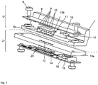
- FIG. 1 illustrates the functional scope of an optically inductive interface according to the invention. It consists of a base unit-side part 2 (see also FIG. 2 ) and a peripheral side part 5.
- the peripheral device side assembly is fixed by means of screws 6 on an inner side 7 of the peripheral device, for example the inner shell of a condensate avoidance hood (the outer shell is not shown in this figure).
- a circuit board 8 houses six optical channels. Four channels transmit data from the condensate avoidance hood to the base unit. Accordingly, there are four infrared LEDs 9 on the circuit board. Two channels transfer data from the base unit to the condensate avoidance hood. For this purpose, there are two photoreceivers 10 on the printed circuit board.
- optical components are in optical connection with their complementary coupling elements in the base unit via openings 11, 12 in the inner shell of the condensate prevention hood 7 and the housing upper side 13a of the base unit.
- optical filters 13b, 14 are placed in the openings 11, 12.
- the power supply for two contained in the condensate prevention hood temperature sensors and an EEPROM (not shown here) and for the six optical channels is realized via an inductive coupling.
- a respective coil 15, 16 are positioned on Kondensatvermeidungshauben and on the side of the device. These are each wound on the central pin of a half-shell core 17, 18 and have for directional conduction of the magnetic field lines lateral webs 30 whose course in sections substantially the course of field lines of the magnetic field (not shown) follows the inductive signal transmission in particular via a Splitting distance or to improve by a housing - on the device side 18 well stylized to recognize and detailed in FIG. 4 , The energy transfer takes place according to the principle of the loosely coupled transformer.
- the condensate avoidance hood On the side of the condensate avoidance hood is also a magnet 19. This is detected by the device side via a Hall sensor 20. Only when the condensate avoidance hood is placed on the base unit in the specific (intended) position and the Hall sensor 20 detects the magnet 19, the coil 16 is energized. This reduces the power loss and the electromagnetic interference of the inductive interface.
- FIG. 3 The installation of the coupling assemblies 2 and 5 after FIG. 1 into a base unit 1 and a peripheral device 31 shows schematically FIG. 3 ,
- FIG. 5 shows an additional magnetic electrical connector with a positioning mandrel or dome 3 ( FIG. 2 ).
- a structurally identical interface is also realized via the second positioning mandrel 4.
- the positioning mandrel 3 made of a ferromagnetic metal is fastened to the upper side 13 of the base unit 1 by means of an electrically conductive screw 21.
- the screw 21 is connected to a power source (not shown here).
- a metallic bush 22 is pressed into the inner shell 7 of the condensate avoidance hood. This has an inner groove 23 into which an annular spring 24 is inserted. If the condensate avoidance hood is placed on the base unit 1, an electrical line contact is made from the positioning mandrel 3 via the annular spring 24 to the socket 22. A power cable (not shown here) is then connected to a heating foil (not shown) in the condensate-preventing hood. The circuit is closed back to the base unit 1 via the second interface by the positioning mandrel 4th
- the plug connection follows FIG. 5 a hold function too.
- a magnet 25 is pressed into the outer shell 26 of the condensate prevention hood. This exerts a magnetic force on the ferromagnetic positioning mandrel 3 when the condensate avoidance hood is attached and thus secures the hood additionally on the base unit 1.
Landscapes
- Chemical & Material Sciences (AREA)
- Chemical Kinetics & Catalysis (AREA)
- Physics & Mathematics (AREA)
- Electromagnetism (AREA)
- Health & Medical Sciences (AREA)
- Clinical Laboratory Science (AREA)
- Engineering & Computer Science (AREA)
- Mechanical Engineering (AREA)
- Devices For Use In Laboratory Experiments (AREA)
- Automatic Analysis And Handling Materials Therefor (AREA)
- Control Of Temperature (AREA)
- Control Of Resistance Heating (AREA)
- Mixers With Rotating Receptacles And Mixers With Vibration Mechanisms (AREA)
Applications Claiming Priority (2)
| Application Number | Priority Date | Filing Date | Title |
|---|---|---|---|
| DE102010019232A DE102010019232B4 (de) | 2010-05-03 | 2010-05-03 | Kondensatvermeidungshaube |
| PCT/EP2011/002191 WO2011138003A1 (de) | 2010-05-03 | 2011-05-03 | Kondensatvermeidungshaube |
Publications (2)
| Publication Number | Publication Date |
|---|---|
| EP2566622A1 EP2566622A1 (de) | 2013-03-13 |
| EP2566622B1 true EP2566622B1 (de) | 2017-04-12 |
Family
ID=44510587
Family Applications (1)
| Application Number | Title | Priority Date | Filing Date |
|---|---|---|---|
| EP11728770.6A Active EP2566622B1 (de) | 2010-05-03 | 2011-05-03 | Kondensatvermeidungshaube |
Country Status (6)
| Country | Link |
|---|---|
| US (2) | US20130266946A1 (ja) |
| EP (1) | EP2566622B1 (ja) |
| JP (1) | JP6042325B2 (ja) |
| CN (1) | CN102939162B (ja) |
| DE (1) | DE102010019232B4 (ja) |
| WO (1) | WO2011138003A1 (ja) |
Families Citing this family (1)
| Publication number | Priority date | Publication date | Assignee | Title |
|---|---|---|---|---|
| DE102011109332A1 (de) * | 2011-08-03 | 2013-02-07 | Eppendorf Ag | Laborvorrichtung und Verfahren zur Behandlung von Laborproben |
Citations (2)
| Publication number | Priority date | Publication date | Assignee | Title |
|---|---|---|---|---|
| US20090120104A1 (en) * | 2007-11-13 | 2009-05-14 | Roche Molecular Systems, Inc. | Thermal block unit |
| EP2340891A1 (en) * | 2009-12-23 | 2011-07-06 | PEQLAB Biotechnologie GmbH | Thermal plate |
Family Cites Families (18)
| Publication number | Priority date | Publication date | Assignee | Title |
|---|---|---|---|---|
| CN87207787U (zh) * | 1987-05-05 | 1988-04-27 | 张玫 | 无垢电热恒温水浴锅 |
| FR2644356B1 (fr) * | 1989-03-20 | 1992-11-20 | Jouan | Procede de concentration d'echantillons par evaporation du solvant et evaporateur-concentrateur centrifuge pour la mise en oeuvre de ce procede |
| AT394323B (de) * | 1989-11-02 | 1992-03-10 | Slt Labinstruments Gmbh | Temperierkammer, insbesondere fuer die temperierung des inhalts einer mikrotitrationsplatte, und verfahren zur steuerung eines heizkreises hiefuer |
| CA2031912A1 (en) * | 1989-12-22 | 1991-06-23 | Robert Fred Pfost | Heated cover device |
| US5567387A (en) * | 1994-11-07 | 1996-10-22 | Johnson & Johnson Clinical Diagnostics, Inc. | Cuvette conveyor and sensor |
| CN2275901Y (zh) * | 1996-09-05 | 1998-03-11 | 涟源钢铁股份有限公司 | 一种玻璃防风罩 |
| DE19646116A1 (de) * | 1996-11-08 | 1998-05-14 | Eppendorf Geraetebau Netheler | Temperierblock mit Aufnahmen |
| US7133726B1 (en) * | 1997-03-28 | 2006-11-07 | Applera Corporation | Thermal cycler for PCR |
| DE19859586C1 (de) * | 1998-12-22 | 2000-07-13 | Mwg Biotech Ag | Thermocyclervorrichtung |
| US7169355B1 (en) * | 2000-02-02 | 2007-01-30 | Applera Corporation | Apparatus and method for ejecting sample well trays |
| EP1322421A2 (en) * | 2000-09-29 | 2003-07-02 | Avantium International B.V. | Assembly of an integrated vessel transporter and at least one reaction vessel for transporting a chemical substance |
| KR101090570B1 (ko) * | 2002-12-09 | 2011-12-08 | 산요덴키 바이오메디칼 가부시키가이샤 | 인큐베이터 |
| GB0311959D0 (en) * | 2003-05-23 | 2003-06-25 | Glaxo Group Ltd | Energy delivery system |
| DE102004052156B4 (de) * | 2004-10-26 | 2007-02-08 | Sartorius Ag | Vorrichtung zum Schütteln von Medien |
| DE102005027555B3 (de) * | 2005-06-14 | 2006-10-05 | Eppendorf Ag | Thermocycler |
| WO2008009311A1 (en) * | 2006-07-17 | 2008-01-24 | Agilent Technologies, Inc. | Temperature adjustment of a fluidic sample within a fluidic device |
| US8393781B2 (en) * | 2006-09-06 | 2013-03-12 | Henry Troemner Llc | Incubating orbital shaker |
| EP2144716B1 (en) * | 2007-05-04 | 2013-02-20 | QUANTIFOIL Instruments GmbH | Sample handling devices and method |
-
2010
- 2010-05-03 DE DE102010019232A patent/DE102010019232B4/de active Active
-
2011
- 2011-05-03 WO PCT/EP2011/002191 patent/WO2011138003A1/de active Application Filing
- 2011-05-03 EP EP11728770.6A patent/EP2566622B1/de active Active
- 2011-05-03 JP JP2013508391A patent/JP6042325B2/ja not_active Expired - Fee Related
- 2011-05-03 CN CN201180029036.7A patent/CN102939162B/zh active Active
- 2011-05-03 US US13/643,948 patent/US20130266946A1/en not_active Abandoned
-
2018
- 2018-03-14 US US15/921,548 patent/US20180304214A1/en not_active Abandoned
Patent Citations (2)
| Publication number | Priority date | Publication date | Assignee | Title |
|---|---|---|---|---|
| US20090120104A1 (en) * | 2007-11-13 | 2009-05-14 | Roche Molecular Systems, Inc. | Thermal block unit |
| EP2340891A1 (en) * | 2009-12-23 | 2011-07-06 | PEQLAB Biotechnologie GmbH | Thermal plate |
Also Published As
| Publication number | Publication date |
|---|---|
| US20180304214A1 (en) | 2018-10-25 |
| DE102010019232B4 (de) | 2013-06-27 |
| WO2011138003A1 (de) | 2011-11-10 |
| DE102010019232A1 (de) | 2011-11-03 |
| JP2013533574A (ja) | 2013-08-22 |
| US20130266946A1 (en) | 2013-10-10 |
| CN102939162A (zh) | 2013-02-20 |
| EP2566622A1 (de) | 2013-03-13 |
| JP6042325B2 (ja) | 2016-12-14 |
| CN102939162B (zh) | 2015-11-25 |
Similar Documents
| Publication | Publication Date | Title |
|---|---|---|
| EP1733239B1 (de) | Vorrichtung und vefahren zum identifizieren, orten und verfolgen von objekten auf laboreinrichtungen | |
| EP2035147B1 (de) | Modulares aufbewahrungssystem für labor-flüssigkeiten | |
| DE102014106877A1 (de) | Modulares Inkubatorsystem | |
| EP0342155A2 (de) | Laboratoriumsgerät zum wahlweisen Heizen und Kühlen | |
| EP2857844B1 (de) | Laborgerät, System und Verfahren zur gerätegesteuerten Behandlung mindestens einer Laborprobe unter Verwendung mindestens eines Verbrauchsartikels | |
| DE102011109332A1 (de) | Laborvorrichtung und Verfahren zur Behandlung von Laborproben | |
| DE102010053913A1 (de) | Verfahren zum Separieren und Detektieren eines Analyten | |
| EP0642828A1 (de) | Reaktionsbehälteranordnung für eine Vorrichtung zur automatischen Durchführung von Tenperaturzyklen | |
| EP2536820A2 (en) | Culture systems, apparatus, and related methods and articles | |
| EP2547431A1 (de) | Positioniereinrichtung für eine funktionseinrichtung | |
| DE102014104279B3 (de) | Messgerät zur thermogravimetrischen Materialfeuchtebestimmung | |
| EP2857842B1 (de) | Zugriffssteuerung für ein Laborgerät, Laborgerät mit Zugriffssteuerung und Verfahren zur gerätegesteuerten Behandlung von Laborproben | |
| EP3988924B1 (de) | Kombination eines mikroplatten-lesegeräts mit einer zubehörvorrichtung | |
| EP2268980A2 (de) | Vorrichtung zum erwärmen eines gegenstands mittels wasserbad | |
| DE102020133420A1 (de) | Laborgerät mit fixiermechanismus zum fixieren eines objektträgers | |
| EP2566622B1 (de) | Kondensatvermeidungshaube | |
| EP1732692A1 (de) | Temperierverfahren und-vorrichtung für die temperaturbehandlung kleiner flüssigkeitsmengen | |
| CN216550412U (zh) | 用于分析核酸的系统 | |
| DE112018007855T5 (de) | Thermocycler und diesen enthaltendes echtzeit-pcr-gerät | |
| DE102019118712A1 (de) | Feldgerät und Gegenstelle | |
| WO2014063912A1 (de) | Vorrichtung und verfahren zur optischen analyse eines materials | |
| DE102004004022B4 (de) | Kochfeld | |
| EP3502231B1 (de) | Bioprozess-steuervorrichtung sowie bioprozess-system | |
| EP2439506B1 (de) | Temperaturmesssystem | |
| EP3217772A1 (de) | Platine für ein elektronisches steuergerät |
Legal Events
| Date | Code | Title | Description |
|---|---|---|---|
| PUAI | Public reference made under article 153(3) epc to a published international application that has entered the european phase |
Free format text: ORIGINAL CODE: 0009012 |
|
| 17P | Request for examination filed |
Effective date: 20121203 |
|
| AK | Designated contracting states |
Kind code of ref document: A1 Designated state(s): AL AT BE BG CH CY CZ DE DK EE ES FI FR GB GR HR HU IE IS IT LI LT LU LV MC MK MT NL NO PL PT RO RS SE SI SK SM TR |
|
| DAX | Request for extension of the european patent (deleted) | ||
| 17Q | First examination report despatched |
Effective date: 20150826 |
|
| GRAP | Despatch of communication of intention to grant a patent |
Free format text: ORIGINAL CODE: EPIDOSNIGR1 |
|
| INTG | Intention to grant announced |
Effective date: 20161214 |
|
| GRAS | Grant fee paid |
Free format text: ORIGINAL CODE: EPIDOSNIGR3 |
|
| GRAA | (expected) grant |
Free format text: ORIGINAL CODE: 0009210 |
|
| AK | Designated contracting states |
Kind code of ref document: B1 Designated state(s): AL AT BE BG CH CY CZ DE DK EE ES FI FR GB GR HR HU IE IS IT LI LT LU LV MC MK MT NL NO PL PT RO RS SE SI SK SM TR |
|
| REG | Reference to a national code |
Ref country code: GB Ref legal event code: FG4D Free format text: NOT ENGLISH |
|
| REG | Reference to a national code |
Ref country code: CH Ref legal event code: EP |
|
| REG | Reference to a national code |
Ref country code: IE Ref legal event code: FG4D Free format text: LANGUAGE OF EP DOCUMENT: GERMAN |
|
| REG | Reference to a national code |
Ref country code: AT Ref legal event code: REF Ref document number: 883313 Country of ref document: AT Kind code of ref document: T Effective date: 20170515 |
|
| REG | Reference to a national code |
Ref country code: DE Ref legal event code: R096 Ref document number: 502011012031 Country of ref document: DE |
|
| REG | Reference to a national code |
Ref country code: FR Ref legal event code: PLFP Year of fee payment: 7 |
|
| REG | Reference to a national code |
Ref country code: NL Ref legal event code: MP Effective date: 20170412 |
|
| REG | Reference to a national code |
Ref country code: LT Ref legal event code: MG4D |
|
| REG | Reference to a national code |
Ref country code: DE Ref legal event code: R082 Ref document number: 502011012031 Country of ref document: DE |
|
| PG25 | Lapsed in a contracting state [announced via postgrant information from national office to epo] |
Ref country code: NL Free format text: LAPSE BECAUSE OF FAILURE TO SUBMIT A TRANSLATION OF THE DESCRIPTION OR TO PAY THE FEE WITHIN THE PRESCRIBED TIME-LIMIT Effective date: 20170412 |
|
| PG25 | Lapsed in a contracting state [announced via postgrant information from national office to epo] |
Ref country code: LT Free format text: LAPSE BECAUSE OF FAILURE TO SUBMIT A TRANSLATION OF THE DESCRIPTION OR TO PAY THE FEE WITHIN THE PRESCRIBED TIME-LIMIT Effective date: 20170412 Ref country code: FI Free format text: LAPSE BECAUSE OF FAILURE TO SUBMIT A TRANSLATION OF THE DESCRIPTION OR TO PAY THE FEE WITHIN THE PRESCRIBED TIME-LIMIT Effective date: 20170412 Ref country code: ES Free format text: LAPSE BECAUSE OF FAILURE TO SUBMIT A TRANSLATION OF THE DESCRIPTION OR TO PAY THE FEE WITHIN THE PRESCRIBED TIME-LIMIT Effective date: 20170412 Ref country code: NO Free format text: LAPSE BECAUSE OF FAILURE TO SUBMIT A TRANSLATION OF THE DESCRIPTION OR TO PAY THE FEE WITHIN THE PRESCRIBED TIME-LIMIT Effective date: 20170712 Ref country code: GR Free format text: LAPSE BECAUSE OF FAILURE TO SUBMIT A TRANSLATION OF THE DESCRIPTION OR TO PAY THE FEE WITHIN THE PRESCRIBED TIME-LIMIT Effective date: 20170713 Ref country code: HR Free format text: LAPSE BECAUSE OF FAILURE TO SUBMIT A TRANSLATION OF THE DESCRIPTION OR TO PAY THE FEE WITHIN THE PRESCRIBED TIME-LIMIT Effective date: 20170412 |
|
| PG25 | Lapsed in a contracting state [announced via postgrant information from national office to epo] |
Ref country code: RS Free format text: LAPSE BECAUSE OF FAILURE TO SUBMIT A TRANSLATION OF THE DESCRIPTION OR TO PAY THE FEE WITHIN THE PRESCRIBED TIME-LIMIT Effective date: 20170412 Ref country code: PL Free format text: LAPSE BECAUSE OF FAILURE TO SUBMIT A TRANSLATION OF THE DESCRIPTION OR TO PAY THE FEE WITHIN THE PRESCRIBED TIME-LIMIT Effective date: 20170412 Ref country code: BG Free format text: LAPSE BECAUSE OF FAILURE TO SUBMIT A TRANSLATION OF THE DESCRIPTION OR TO PAY THE FEE WITHIN THE PRESCRIBED TIME-LIMIT Effective date: 20170712 Ref country code: IS Free format text: LAPSE BECAUSE OF FAILURE TO SUBMIT A TRANSLATION OF THE DESCRIPTION OR TO PAY THE FEE WITHIN THE PRESCRIBED TIME-LIMIT Effective date: 20170812 Ref country code: SE Free format text: LAPSE BECAUSE OF FAILURE TO SUBMIT A TRANSLATION OF THE DESCRIPTION OR TO PAY THE FEE WITHIN THE PRESCRIBED TIME-LIMIT Effective date: 20170412 |
|
| REG | Reference to a national code |
Ref country code: DE Ref legal event code: R097 Ref document number: 502011012031 Country of ref document: DE |
|
| PG25 | Lapsed in a contracting state [announced via postgrant information from national office to epo] |
Ref country code: CZ Free format text: LAPSE BECAUSE OF FAILURE TO SUBMIT A TRANSLATION OF THE DESCRIPTION OR TO PAY THE FEE WITHIN THE PRESCRIBED TIME-LIMIT Effective date: 20170412 Ref country code: RO Free format text: LAPSE BECAUSE OF FAILURE TO SUBMIT A TRANSLATION OF THE DESCRIPTION OR TO PAY THE FEE WITHIN THE PRESCRIBED TIME-LIMIT Effective date: 20170412 Ref country code: SK Free format text: LAPSE BECAUSE OF FAILURE TO SUBMIT A TRANSLATION OF THE DESCRIPTION OR TO PAY THE FEE WITHIN THE PRESCRIBED TIME-LIMIT Effective date: 20170412 Ref country code: MC Free format text: LAPSE BECAUSE OF FAILURE TO SUBMIT A TRANSLATION OF THE DESCRIPTION OR TO PAY THE FEE WITHIN THE PRESCRIBED TIME-LIMIT Effective date: 20170412 Ref country code: EE Free format text: LAPSE BECAUSE OF FAILURE TO SUBMIT A TRANSLATION OF THE DESCRIPTION OR TO PAY THE FEE WITHIN THE PRESCRIBED TIME-LIMIT Effective date: 20170412 Ref country code: DK Free format text: LAPSE BECAUSE OF FAILURE TO SUBMIT A TRANSLATION OF THE DESCRIPTION OR TO PAY THE FEE WITHIN THE PRESCRIBED TIME-LIMIT Effective date: 20170412 |
|
| PLBE | No opposition filed within time limit |
Free format text: ORIGINAL CODE: 0009261 |
|
| STAA | Information on the status of an ep patent application or granted ep patent |
Free format text: STATUS: NO OPPOSITION FILED WITHIN TIME LIMIT |
|
| REG | Reference to a national code |
Ref country code: IE Ref legal event code: MM4A |
|
| PG25 | Lapsed in a contracting state [announced via postgrant information from national office to epo] |
Ref country code: SM Free format text: LAPSE BECAUSE OF FAILURE TO SUBMIT A TRANSLATION OF THE DESCRIPTION OR TO PAY THE FEE WITHIN THE PRESCRIBED TIME-LIMIT Effective date: 20170412 Ref country code: IT Free format text: LAPSE BECAUSE OF FAILURE TO SUBMIT A TRANSLATION OF THE DESCRIPTION OR TO PAY THE FEE WITHIN THE PRESCRIBED TIME-LIMIT Effective date: 20170412 |
|
| 26N | No opposition filed |
Effective date: 20180115 |
|
| PG25 | Lapsed in a contracting state [announced via postgrant information from national office to epo] |
Ref country code: LU Free format text: LAPSE BECAUSE OF NON-PAYMENT OF DUE FEES Effective date: 20170503 |
|
| PG25 | Lapsed in a contracting state [announced via postgrant information from national office to epo] |
Ref country code: IE Free format text: LAPSE BECAUSE OF NON-PAYMENT OF DUE FEES Effective date: 20170503 |
|
| REG | Reference to a national code |
Ref country code: FR Ref legal event code: PLFP Year of fee payment: 8 |
|
| PG25 | Lapsed in a contracting state [announced via postgrant information from national office to epo] |
Ref country code: SI Free format text: LAPSE BECAUSE OF FAILURE TO SUBMIT A TRANSLATION OF THE DESCRIPTION OR TO PAY THE FEE WITHIN THE PRESCRIBED TIME-LIMIT Effective date: 20170412 |
|
| REG | Reference to a national code |
Ref country code: AT Ref legal event code: MM01 Ref document number: 883313 Country of ref document: AT Kind code of ref document: T Effective date: 20170503 |
|
| PG25 | Lapsed in a contracting state [announced via postgrant information from national office to epo] |
Ref country code: AT Free format text: LAPSE BECAUSE OF NON-PAYMENT OF DUE FEES Effective date: 20170503 |
|
| PG25 | Lapsed in a contracting state [announced via postgrant information from national office to epo] |
Ref country code: MT Free format text: LAPSE BECAUSE OF FAILURE TO SUBMIT A TRANSLATION OF THE DESCRIPTION OR TO PAY THE FEE WITHIN THE PRESCRIBED TIME-LIMIT Effective date: 20170412 |
|
| PG25 | Lapsed in a contracting state [announced via postgrant information from national office to epo] |
Ref country code: HU Free format text: LAPSE BECAUSE OF FAILURE TO SUBMIT A TRANSLATION OF THE DESCRIPTION OR TO PAY THE FEE WITHIN THE PRESCRIBED TIME-LIMIT; INVALID AB INITIO Effective date: 20110503 |
|
| PG25 | Lapsed in a contracting state [announced via postgrant information from national office to epo] |
Ref country code: CY Free format text: LAPSE BECAUSE OF NON-PAYMENT OF DUE FEES Effective date: 20170412 |
|
| PG25 | Lapsed in a contracting state [announced via postgrant information from national office to epo] |
Ref country code: MK Free format text: LAPSE BECAUSE OF FAILURE TO SUBMIT A TRANSLATION OF THE DESCRIPTION OR TO PAY THE FEE WITHIN THE PRESCRIBED TIME-LIMIT Effective date: 20170412 |
|
| PG25 | Lapsed in a contracting state [announced via postgrant information from national office to epo] |
Ref country code: TR Free format text: LAPSE BECAUSE OF FAILURE TO SUBMIT A TRANSLATION OF THE DESCRIPTION OR TO PAY THE FEE WITHIN THE PRESCRIBED TIME-LIMIT Effective date: 20170412 |
|
| PG25 | Lapsed in a contracting state [announced via postgrant information from national office to epo] |
Ref country code: PT Free format text: LAPSE BECAUSE OF FAILURE TO SUBMIT A TRANSLATION OF THE DESCRIPTION OR TO PAY THE FEE WITHIN THE PRESCRIBED TIME-LIMIT Effective date: 20170412 |
|
| PG25 | Lapsed in a contracting state [announced via postgrant information from national office to epo] |
Ref country code: AL Free format text: LAPSE BECAUSE OF FAILURE TO SUBMIT A TRANSLATION OF THE DESCRIPTION OR TO PAY THE FEE WITHIN THE PRESCRIBED TIME-LIMIT Effective date: 20170412 |
|
| REG | Reference to a national code |
Ref country code: FR Ref legal event code: PLFP Year of fee payment: 12 |
|
| REG | Reference to a national code |
Ref country code: DE Ref legal event code: R081 Ref document number: 502011012031 Country of ref document: DE Owner name: EPPENDORF SE, DE Free format text: FORMER OWNER: EPPENDORF AG, 22339 HAMBURG, DE |
|
| P01 | Opt-out of the competence of the unified patent court (upc) registered |
Effective date: 20230527 |
|
| REG | Reference to a national code |
Ref country code: BE Ref legal event code: PD Owner name: EPPENDORF SE; DE Free format text: DETAILS ASSIGNMENT: CHANGE OF OWNER(S), CHANGE OF LEGAL ENTITY Effective date: 20230222 |
|
| REG | Reference to a national code |
Ref country code: BE Ref legal event code: PD Owner name: EPPENDORF SE; DE Free format text: DETAILS ASSIGNMENT: CHANGE OF OWNER(S), CHANGE OF LEGAL ENTITY; FORMER OWNER NAME: EPPENDORF AG Effective date: 20230731 |
|
| PGFP | Annual fee paid to national office [announced via postgrant information from national office to epo] |
Ref country code: GB Payment date: 20240521 Year of fee payment: 14 |
|
| PGFP | Annual fee paid to national office [announced via postgrant information from national office to epo] |
Ref country code: DE Payment date: 20240521 Year of fee payment: 14 |
|
| PGFP | Annual fee paid to national office [announced via postgrant information from national office to epo] |
Ref country code: CH Payment date: 20240602 Year of fee payment: 14 |
|
| PGFP | Annual fee paid to national office [announced via postgrant information from national office to epo] |
Ref country code: FR Payment date: 20240528 Year of fee payment: 14 |
|
| PGFP | Annual fee paid to national office [announced via postgrant information from national office to epo] |
Ref country code: LV Payment date: 20240517 Year of fee payment: 14 Ref country code: BE Payment date: 20240521 Year of fee payment: 14 |