EP2566414B1 - Bladder prosthesis for subcutaneous implantation - Google Patents
Bladder prosthesis for subcutaneous implantation Download PDFInfo
- Publication number
- EP2566414B1 EP2566414B1 EP11718978.7A EP11718978A EP2566414B1 EP 2566414 B1 EP2566414 B1 EP 2566414B1 EP 11718978 A EP11718978 A EP 11718978A EP 2566414 B1 EP2566414 B1 EP 2566414B1
- Authority
- EP
- European Patent Office
- Prior art keywords
- valve
- liquid container
- urinary bladder
- openings
- bladder prosthesis
- Prior art date
- Legal status (The legal status is an assumption and is not a legal conclusion. Google has not performed a legal analysis and makes no representation as to the accuracy of the status listed.)
- Active
Links
Images


Classifications
-
- A—HUMAN NECESSITIES
- A61—MEDICAL OR VETERINARY SCIENCE; HYGIENE
- A61F—FILTERS IMPLANTABLE INTO BLOOD VESSELS; PROSTHESES; DEVICES PROVIDING PATENCY TO, OR PREVENTING COLLAPSING OF, TUBULAR STRUCTURES OF THE BODY, e.g. STENTS; ORTHOPAEDIC, NURSING OR CONTRACEPTIVE DEVICES; FOMENTATION; TREATMENT OR PROTECTION OF EYES OR EARS; BANDAGES, DRESSINGS OR ABSORBENT PADS; FIRST-AID KITS
- A61F2/00—Filters implantable into blood vessels; Prostheses, i.e. artificial substitutes or replacements for parts of the body; Appliances for connecting them with the body; Devices providing patency to, or preventing collapsing of, tubular structures of the body, e.g. stents
- A61F2/02—Prostheses implantable into the body
- A61F2/04—Hollow or tubular parts of organs, e.g. bladders, tracheae, bronchi or bile ducts
- A61F2/042—Urinary bladders
Definitions
- the invention relates to a urinary bladder prosthesis for the subcutaneous implantation, which allows a continent urinary diversion.
- the invention finds its application in medicine as a replacement for the bladder, which has been removed due to disease or due to destruction or is inoperative.
- Ureters are delicate vessel-like structures that run from the kidneys to the bladder in the posterior abdomen.
- the ureters may be pushed or destroyed by a growing tumor.
- the ureters will be narrowed by scar tissue, so that they can no longer adequately discharge the urine into the bladder.
- Total removal of the urinary bladder is required, for example, in tumors originating from the bladder itself or in tumors of the surrounding organs such as, in particular, the intestine, uterus or vagina, which have already undergone invasion into the bladder.
- the original urinary bladder is either replaced by autologous intestinal components that have been eliminated from the intestinal continuity, or a switched-off intestinal segment is implanted into the skin as an incontinent urostoma.
- the first method places relatively clearly formulated requirements on the patients concerned. It must be met tumor-surgical and anatomical conditions. Pre- or post-treatments, such as radiotherapy or new surgical procedures in the neobladder operation area limit this surgical procedure. In cases with advanced tumor findings or infestation of neighboring organs or structures, orthotopic urinary bladder replacement surgery as described above is also not standard. This is also true for Tumor entities of other disciplines, such as surgery or gynecology with bladder infiltration too. Again, only incontinent urinary diversion procedures are possible.
- urinary diversions have been implanted, which are connected to extracorporeal collecting systems and discharge the urine incontinently (eg percutaneous nephrostomies or urinaloma with collecting bags).
- urine incontinently eg percutaneous nephrostomies or urinaloma with collecting bags.
- a urinary bladder prosthesis which allows for a continual procedure in a simple application, can overcome these disadvantages.
- FR 2 116 838 discloses an artificial bladder to be connected to two ureters and to the urethra of a patient.
- This bladder is equipped with a system of three internal flap valves, two of which provide urine flow to the inlet, while a third opposite to the two flap valves works in counter-pressure (drain).
- the artificial bladder is provided with a flap control means which provides control over a gas which is in a separate system.
- the system includes a control device for controlling the pressure in the urinary bladder.
- FR 2 255 877 discloses an implantable urinary bladder prosthesis suitable for connection to the ureter and urethra of a patient.
- the connection to the kidneys can also be made via ureteral prostheses.
- the urinary bladder prosthesis can be connected directly to the abdominal or perineal septum of the patient without the urethra.
- the disclosed urinary bladder prosthesis is intended to provide the main functions of a natural urinary bladder and to be controlled naturally.
- the prosthesis described has no internal, ie used in patients, valve flaps.
- the disclosed urinary bladder prosthesis is deformable and is thereby tensioned upon entry of the urine and relaxes during deflation.
- DE 101 56 558 A1 discloses a closure system and method suitable for selectively opening and closing a tubular body organ, e.g. B. an artificial bladder.
- the closure system comprises a closure element and a control system controlling the closure element.
- the control system adjusts a first state of the closure system and self-regulates therefrom a deviation from the first state to temporarily counteract pressure increases occurring in the plastic urine bladder to be occluded. This is to avoid potential damage to the artificial bladder, resulting from an excessive internal pressure of the container.
- the implantable closure system includes sensor elements, supply lines, a pumping device, shut-off valves and also an implanted energy source for the safe operation of the system.
- EP 0 818 978 B1 discloses a urinary bladder prosthesis system for subcutaneous implantation composed of multiple components. It comprises a bag element made of biocompatible material and a valve element for controlling the inflow and outflow of the urine to the bag element. The inlet and outlet of the urine is ensured in this apparatus via a single, complex designed, closable and the drain ensuring valve element.
- the system disclosed requires a high degree of technical understanding on the part of both the surgeon and the patient.
- the artificial bladder is made of a material which is a biocompatible elastic plastic and is designed with two chambers which are connected to each other via a check valve.
- the chambers each have a bottom which is formed by a foil wall.
- the first chamber is connected to a kidney, the other chamber to the drain.
- the urine is sucked in by the artificial bladder (self-priming system).
- the check valve located between the two chambers opens and allows fluid to flow into the second chamber. The emptying takes place by manual pressure on the chamber or by pumping action.
- DE 698 21 117 T2 discloses a subcutaneously implantable urinary bladder prosthesis of a bilayered material having a central reservoir to which tubular elements are attached as an artificial ureter and an artificial urethra. Within the artificial urethra, an artificial urethral sphincter is attached, which is located in front of the pubis after implantation. This is a differently shaped valve element which is opened by pressure on the reservoir.
- the reservoir is in DE 698 21 117 T2 designed so that the two materials for the inner and outer walls of the reservoir are not connected to allow interchangeability of the inner liquid bag.
- an interchangeability of the inner fluid bag requires a complex release of at least three fixation points on the outer material (inlet and outlet openings).
- the inner fluid bag in this construction can only contract when air penetrates between the two layers of material. Since this is impossible, the liquid bag remains adherent to the outer wall by adhesion so that incomplete evacuation may result.
- the design of the artificial urethral sphincter in the midst of the tubular element for the artificial urethra and the implantation in front of the pubic bone should possibly allow a compression of the artificial urethra.
- the accessibility of the urethral sphincter is particularly difficult in obese patients, so that there is a need for further emptying variants to use subcutaneously implantable urinary bladder prostheses universally. Furthermore, it must be absolutely prevented that a return of urine to the kidneys is possible.
- US 4,969,902 A discloses a multi-layer artificial gut outlet with corresponding openings.
- the solution is also to be applicable to a urinary bladder prosthesis, but would lead to problems in emptying the bladder due to the material layer structure.
- EP 0 972 496 A2 discloses an implant holder for body implants, eg an artificial bladder.
- the implant holder has a shielding wall (21) which on one side consists of a tissue-friendly fibrous material (25) for growing endogenous cells and on the other side has a smooth contact surface (23) for the implant (10).
- the implant holder prevents the body tissue from growing directly on the implant, which would make replacement of the implant (10) difficult.
- To replace the skin (16) of the patient is cut open and the holder (26). The implant holder remains in the body while the implant (10) is changed.
- the object of the invention is to provide a urinary bladder prosthesis which is suitable for subcutaneous implantation and which permits continual removal of urine in a simple operation. Furthermore, the urinary bladder prosthesis should be designed so that it can be implanted as part of a minimally invasive surgery and can be easily replaced surgically.
- a urinary bladder prosthesis with the features of claim 1 and a kit for the preparation of a urinary bladder prosthesis according to claim 9. Further refinements include the dependent claims 2 to 8 or 10 to 12th
- the urinary bladder prosthesis for subcutaneous implantation comprises a flexible, substantially tubular fluid container, the wall of which contains at least two interconnected layers of material having front and rear sides, at least the front side of which has stabilizing elements, and two openings at the lateral ends for the inlet of liquid and having at least one opening for the outflow of liquid.
- the openings are stabilized or rigidly designed such that they Attachment of valve or hose elements are suitable.
- a check valve is arranged or it is arranged at one of the openings, a check valve and the other opening is closed with a sealing plug.
- the outer layer of the liquid container wall is made of bio-inert material, preferably an organic polymer, in particular polyester, preferably polyethylene terephthalate (PET), preferably Dacron® .
- the inner layer of the liquid container wall is smooth and consists of a chemically inert material, preferably of an organic polymer, in particular silicone.
- the material layers of the wall of the liquid container are connected to one another in a material-locking manner.
- a manually operable valve element or a tube element which contains a manually operable valve is arranged on at least one of the openings for the outflow of fluid. By manual operation of the valve, a continental discharge of liquid from the liquid container is ensured.
- the mechanical stabilization of the container wall and the manually-open valve prevent uncontrolled emptying of the urinary bladder prosthesis in case of accidental pressure on the liquid container. Since the urinary bladder prosthesis is designed for subcutaneous implantation, an operation via manually operable valves is ensured and a simple surgical exchange of components of the urinary bladder prosthesis is possible in a minimally invasive manner.
- the liquid container of the urinary bladder prosthesis according to the invention has a front and a back side, of which at least the front side has stabilizing elements. Further, the liquid container at the lateral ends one or two, preferably two, openings for the supply of liquid and at least one, preferably one or two, openings for the outflow of liquid.
- the openings are stabilized or rigidly designed such that they are suitable for fastening valve or hose elements.
- the liquid container is designed to be flexible, so that the subcutaneous movement after instrumental expansion and establishment of the necessary preferably suprasymphysäre cavity is easily possible.
- “flexible” in the sense of the invention is to be understood that the liquid container is elastic and flexible and can return to the original form after elimination of a force.
- the liquid container is produced by casting or spraying.
- the liquid container is suitable for subcutaneous implantation. It has two longitudinal sides, one of which faces the outside of the body after implantation (also referred to herein as the front side) and the other one faces the internal organs (also referred to herein as the posterior side).
- the front side faces the outside of the body after implantation
- the posterior side faces the internal organs
- at least one of the sides contains stabilizing elements incorporated in the wall of the liquid container. Possibly. the entire wall of the liquid container (front and rear side) may have stabilizing elements.
- Stabilizing elements cause the material or material to be sufficiently flexible to be suitable for subcutaneous implantation, yet being pressure stable to the extent necessary against external force, so that no destruction or plastic deformation by normally occurring force influences (eg. Sneezing, coughing, blow on the stomach) is possible.
- normally occurring force influences eg. Sneezing, coughing, blow on the stomach
- mechanical stabilizations are used to ensure the pressure stability.
- framework structures also referred to as support structures.
- the framework structures are preferably designed as a spiral, spring, ribs or cylindrical or cuboidal connecting pieces (eg rods). They can consist of solid material as well as grid or net structures.
- the framework structures are designed so that they are uniformly distributed or arranged throughout the length of the urinary bladder prosthesis.
- Preferred materials for framework structures are metals and / or polymers.
- Preferred support structures are spring metal skeletons.
- stabilizations by stabilizing elements are preferably ensured by increasing the material thickness (thickness of the liquid container wall) or as rib skeleton from the base material and / or by the container wall containing at least one further material layer as intermediate layer between the outer and inner material layer as stabilizing element.
- the material of the liquid container has memory properties, ie that the liquid container assumes its original shape with decreasing force. This is important for the emptying of the urinary bladder prosthesis according to the invention, since during emptying no air should flow into the urinary bladder prosthesis.
- the front and rear walls of the liquid container approach when emptying the urinary bladder prosthesis, during filling by Inflow of urine, the liquid container unfolds due to the memory properties of the material without much pressure.
- the wall of the liquid container contains at least two intimately connected material layers (in particular materially, preferably by bonding the materials of the individual layers), of which the inner layer forms the inner wall of the liquid container and the outer layer forms the outer wall of the liquid container.
- the inner wall of the liquid container and the outer wall of the liquid container are preferably made of different materials.
- the inner wall of the liquid container (also referred to as “container inner wall”) consists of chemically inert material.
- chemically inert in this context, those materials are to be understood that react after implantation of a urinary bladder prosthesis according to the invention or only to a negligible degree with potential reactants. This means that materials of the inner wall of the container do not or only to a small extent react with components of the urine.
- the container inner wall is smooth, d. H. it preferably has no holes, cracks, bumps or bumps. This is necessary to avoid solid deposits of urine at predestined points of the inner wall of the liquid container.
- the container inner wall is made of a flexible polymer, which is preferably synthetic or semisynthetic. This is preferably selected to have a low surface tension so that it does not adhere to itself.
- Particularly preferred materials for the inner wall of the liquid container (or the inner layer of the liquid container wall) are silicones (poly (organo) siloxanes).
- the outer wall of the liquid container is made of a bio-inert material.
- bioinert in this context are meant those materials which do not exert any damaging and immunogenic effect on the human body and do not react with surrounding substances and thereby corrode, for example. Bioinert materials lead after implantation to virtually no chemical and / or biological interaction between the material and the surrounding tissue. Virtually no toxic substances are released.
- the container outer wall consists of at least one (preferably organic) polymer, which is preferably semi-synthetic or synthetic.
- Particularly preferred materials for the outer wall of the liquid container are polyethylene terephthalate (PET), very particularly preferably Dacron ®, ® diols, Tergal ®, Terylene or Trevira ® ®.
- PET polyethylene terephthalate
- the outer wall has a rough surface.
- the outer wall of the liquid container from a continuous sheath of a bio-inert plastic, preferably PET, shown, which as a coating on the inside Material or the internal material layers is present.
- the liquid container has a shape that is substantially tubular and has one or two, preferably two, openings at the lateral ends.
- a substantially tubular shape is meant that the liquid container is formed in a tubular shape, wherein the inner diameter of the tube at the longitudinal side of the container is preferably larger than the inner diameter at the lateral ends.
- the liquid container preferably has a symmetrical, in particular axisymmetric shape.
- the liquid container preferably has the shape of a circular ring segment.
- the lateral openings of the liquid container are used for the supply of liquid.
- the material of the liquid container is stabilized at the openings or rigid.
- the openings are configured with a conical shape.
- the liquid container contains at least one, preferably at least one, preferably one or two, openings for the outflow of liquid (also referred to herein as discharge openings). These are preferably arranged in the middle of the liquid container between the terminal openings. Particularly preferably, two openings are arranged in the middle of the liquid container, wherein these are offset from each other at an angle of approximately 90 °.
- This has the background that, when implanted, the liquid container is attached with an opening in the required direction (eg, caudal or ventral) as required by the patient.
- the other opening is preferably closed in this case by a blind plug.
- Both the lateral openings and the openings provided for the drainage of liquid are designed so that they are suitable for fastening valve or hose elements. This is accomplished by stabilizing the apertures by preferably using metal structures (preferably as a ring) or other stabilized materials (preferably stabilizing elements) for the design of the apertures.
- Preferred variants for stabilizing the openings are the selection of stabilized materials in combination with an increased thickness of the wall of the liquid container and the installation of support structures, preferably metallic support structures.
- the support structures are incorporated into the liquid container in casting or spray processes.
- Valve and hose elements can be attached to the openings. Valve elements are attached directly to an opening of the urinary bladder prosthesis according to the invention preferably via hose connectors.
- hose members herein is meant a separate hose or hose having a valve disposed thereon.
- a check valve is arranged.
- Check valves are used to prevent pressure transmission to the kidneys when emptying the fluid reservoir or when pressure is applied to the fluid reservoir.
- the attachment of the valves is preferably accomplished by hose connectors.
- Check valves have the advantage that the withdrawal of urine from the interior of the urinary bladder prosthesis is prevented in the artificial ureters.
- check valves all valves are suitable, which determine the flow direction of the liquid (the urine) so that only the flow from the kidneys to the liquid container takes place. The passage of the urine in the opposite direction (from the fluid reservoir to the kidneys) is automatically blocked by check valves.
- Fluttering valves are preferably used as check valves.
- Flutter valves open in the forward direction and close automatically without any other external drive, only due to pressure differences on the two sides of the valve.
- Flutter valves are preferably made of elastic material, whose properties at the same time ensures the closing of the valve and yet is so stiff that the valve function is ensured.
- the check valves are preferably made of inert plastic, in particular silicone.
- a manually operable valve element or a hose element which contains a manually operable valve is arranged on at least one outflow opening.
- the openings without valve or hose element are preferably closed with a blind plug.
- a blind plug is to be understood as a sealing plug which preferably consists of the same material as the liquid container. At a minimum, the materials of the inside and outside of the blind plug are the same as the inside and outside of the liquid container.
- the blind plug is preferably designed so that no unevenness or gaps in the container inner wall and container outer wall occur during the closure of the opening. If necessary, blind plugs are also arranged on one of the lateral openings of the liquid container.
- this valve is preferably arranged terminally on the hose member.
- the attachable to the drain openings valve designs can be designed differently. They are preferably designed so that a manual operation of the valve by the patient is possible. This is preferably done by a valve to be opened by manual pressure (on the valve) (herein “pressure port valve") or a catheterizable valve.
- the valve is connected to the urinary bladder prosthesis via the outflow opening directly or via a hose, preferably via an artificial urethra known from the prior art.
- the valve is preferably designed such that, at a prevailing system pressure, the maximum permissible system pressure for which the urinary bladder prosthesis is designed, exceeds, automatically opens and allows drainage of fluid. This prevents uncontrolled leakage of urine within the body.
- a catheterizable valve is attached directly to a drain opening.
- the possibly existing second drain opening is preferably closed with a blanking plug.
- the manually operated valves are preferably self-closing, in particular self-closing catheterisable valves or self-closing pressure-opening valves.
- Self-closing valves are preferably made of elastic materials.
- the self-closing pressure-opening valve is preferably designed as a longitudinal slot or Phillips valve and is opened by pressure from the outside to the valve. An automatic closing of the valve takes place when no radial pressure is exerted on the valve.
- Phillips valves have the additional advantage that an opening can be made in almost any position, without having to pay attention to the position of the valve.
- the Leksschlitz- or Phillips valve is designed as a piston-shaped elastic segment, which is equipped with closure pad or sealing lips and having the longitudinal slot or Phillips inside. In the non-manipulated state close the sealing pads or sealing lips tight and a drain of liquid is not possible. After compressing the piston-shaped segment, the slot is opened and a drain of liquid is made possible. When the pressure is released, the closing cushions or sealing lips returning to their elastic basic shape close automatically.
- a self-closing pressure-opening valve is used in particular in connection with a hose element which is connected to the liquid container of the urinary bladder prosthesis.
- This embodiment of the invention is particularly for use in male patients wherein the implantation of the tubular element into the original urethra and the valve is placed at the distal end of the tubular element in the penile shaft. By compressing the penile shaft, the valve is opened and the fluid is discharged from the urinary bladder prosthesis. When the pressure drops, the valve closes automatically.
- the manually operable valve is preferably made of a chemically inert material, in particular silicone.
- valves in combination with hose elements valve with hose element are particularly preferably formed in one piece. In this way, no subsequent connection of the two parts, which can lead to bumps and deposits of components of the urine.
- a hose element is attached to a drain opening.
- the possibly existing second drain opening is preferably closed with a blanking plug.
- the tube element comprises an artificial urethra (artificial urethra) in combination with a valve, preferably a pressure-opening valve, in particular a self-closing longitudinal slotted or phillips valve which is attached end-to-end to the artificial urethra.
- Artificial urethras are known in the art.
- the artificial urethra is connected at one end to the drainage port of the urinary bladder prosthesis. At the other end of the artificial urethra is a valve.
- any other tube elements can be attached to the drainage holes, which are flexible and whose outer wall is made of bio-inert material.
- the maximum capacity of the liquid container of a urinary bladder prosthesis according to the invention is preferably selected according to the individual needs of a patient. It is preferably at most 500 ml, more preferably 400 to 500 ml.
- a kit according to the invention can advantageously be adapted to the needs of the patient urinary bladder prosthesis assembled directly before implantation.
- the individual parts of the kit are present individually or as a set in sterile packaged form.
- a liquid container is analogous to a), one or two check valves according to b), a catheterizable valve analogous to c) and one or two dummy plugs analogous to e) included.
- a liquid container is analogous to a), one or two non-return valves according to b), a hose element according to c), a pressure-opening valve according to d) and one or two blind stoppers according to e).
- a liquid container analogous to a) and one or two check valves according to b) and a catheterizable valve analogous to c) are included.
- the manually operable valve is configured as described above.
- a self-closing valve in particular a catheterizable valve or pressure-opening valve, is included in the kit. If a hose element is included in the kit according to the invention, then the hose element with valve is very particularly preferably made in one piece.
- Urinary bladder prostheses according to the invention are used as follows: A urinary bladder prosthesis according to the invention is implanted subcutaneously in a patient. The openings at the lateral ends of the liquid container are connected via check valves with artificial ureters, which are also implanted subcutaneously. Such artificial ureters are known in the art. By using such valves, reflux of urine from the urinary bladder prosthesis to the kidneys is avoided.
- the second lateral opening of the liquid container is preferably closed with a blanking plug.
- the urinary bladder prosthesis according to the invention is implanted in such a way that the side of the liquid container which has stabilizing elements is arranged to the outer side of the body, which is directed away from the abdominal cavity.
- the possibly configured without additional stabilization side of the urinary bladder prosthesis is located after implantation on the inner, the abdominal cavity and thus the internal organs side facing.
- a manually operated valve element or a hose element is attached.
- the possibly existing other drain opening is preferably closed, preferably by a blind plug.
- the emptying of the urinary bladder implant according to the invention takes place by opening the valve.
- a catheterizable valve is arranged directly or via a hose element to the outflow opening, the emptying of the urinary bladder prosthesis takes place by catheterization.
- a catheter is manually inserted (for example through the navel), the valve is opened thereby and the urinary bladder prosthesis is emptied.
- the valve preferably closes by itself.
- the catheterizable valve is mounted suprasymphysally-cutaneously upon implantation in the patient.
- the artificial urethra is preferably implanted inside the original urethra so as to terminate in front of the inner orifice of the urethra.
- the urinary bladder prosthesis is thus completely inside the body after implantation and has no contact to the outside.
- the preferably attached to the end of the artificial urethra valve can preferably be opened by pressure from the outside of the valve or by catheterization and the urinary bladder prosthesis are thereby emptied.
- the valves used are self-closing.
- the filling of the urinary bladder prosthesis takes place via the lateral openings of the liquid container.
- Urine is transported from the kidneys into the fluid container.
- the outflow is through manual actuation of a valve attached directly to the discharge opening or of a valve which is connected to the discharge opening via a hose element.
- the container inner walls of the front and rear side of the liquid container are on each other.
- the urinary bladder prosthesis is preferably tubular in the liquid-filled state.
- the internal pressure decreases, causing the fluid reservoir to return to its initial state. This effect can be enhanced advantageously by the pressure exerted by the surrounding organs and tissues, or by manual pressure (eg, hand pressure on the abdomen).
- the urinary bladder prosthesis according to the invention is designed so that a continental discharge of the urine from the interior of the urinary bladder prosthesis is possible. This is ensured by a valve which allows manual opening and closing. Discharge of the urine can therefore be carried out manually with the urinary bladder prosthesis according to the invention, preferably by the patient himself. This is not done by exerting pressure on the liquid container, as in previously proposed solutions, but by manual actuation of a valve, such as a catheterizable valve or pressure relief valve. Upon manual opening of the valve, pressure applied to the fluid container may facilitate or accelerate the depletion of the implanted urinary bladder prosthesis of the invention. However, the opening of the valve does not occur by the pressure exerted on the liquid container.
- a urinary bladder prosthesis according to the invention By means of a urinary bladder prosthesis according to the invention, it is avoided that the aforementioned disadvantages of incontinent urinary diversion occur.
- a decisive advantage for the patient is that in the urinary bladder prostheses according to the invention no extracorporeal bag systems are necessary, which must be constantly worn and emptied and mean a significant restriction of the quality of life.
- the operation of a urinary bladder prosthesis according to the invention does not require a high technical understanding, the emptying is carried out by simple valves manually, preferably by the patient or by Kathethermaschine.
- a simple surgical replacement of individual components in the event of a fault or in the case of complications is advantageously possible.
- the individual parts can be inserted separately as needed and, if necessary, replaced during use misappropriation (for example in the event of a defect due to calcification). This can be done as part of a minimally invasive surgery.
- At least one lateral incision is made in the abdominal wall in the patient.
- a urinary bladder prosthesis according to the invention is introduced subcutaneously.
- a urinary bladder prosthesis During the implantation of a urinary bladder prosthesis according to the invention, the following steps are further carried out: In the event that only one side of the liquid container contains stabilizing elements, the implantation takes place so that the stabilized side of the liquid container points outward from the patient's point of view. The urinary bladder prosthesis is placed in the middle of the body.
- the lateral openings of the liquid container are connected to the ends of subcutaneously implanted artificial ureters.
- Previously check valves are connected at the openings (preferably by plug connections).
- the fixation is performed by suturing the sheaths of artificial ureters and the surface of the liquid container (outer wall) with non-absorbable suture.
- the unused lateral opening of the liquid container is closed with a blind plug.
- the outer wall of the liquid container is sewn to the outer material of the dummy plug.
- the discharge opening in the middle of the liquid container is provided with a valve or hose element.
- the outer wall of the liquid container is optionally sewn with the outer materials of the connected elements.
- the possibly existing unused drainage opening is closed with a blind plug and the outer materials are sewn.
- the subcutaneous implantation of a urinary bladder prosthesis offers the advantages that a simple, minimally invasive surgery for implantation can be performed. These are associated with lower risks for the patient and also allow for a shorter recovery time after surgery. In case of defects, the urinary bladder prosthesis or parts thereof can be easily replaced surgically.
- inventive urinary bladder prostheses is in the FIGS. 1 to 4 shown.
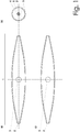
- Fig. 1 shows a urinary bladder prosthesis according to the invention with a symmetrical liquid container (1) with two openings (3) for the discharge of liquid.
- the tubular liquid container (1) has two lateral openings (2) for the inlet of liquid and in the middle two openings (3) for the discharge of liquid. These openings (3) are offset by approximately 90 ° to each other.
- the wall of the liquid container (1) consists of two layers of material, one of which forms the inner wall (5) and one the outer wall (4).
- the liquid container (1) has a front and a hind side with stabilizing elements.
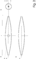
- Fig. 2 shows a urinary bladder prosthesis according to the invention with a symmetrical liquid container (1) with an opening (3) for the discharge of liquid.
- the tubular liquid container (1) has two lateral openings (2) for the inlet of liquid and in the center an opening (3) for the discharge of liquid.
- the wall of the liquid container (1) consists of two layers of material, one of which forms the inner wall (5) and one the outer wall (4).
- the liquid container (1) has a front and a hind side with stabilizing elements.
- To stabilize framework structures are preferably incorporated into the wall of the liquid container and / or the material thickness of the container wall is increased.
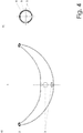
- Fig. 3 shows a urinary bladder prosthesis according to the invention with a liquid container (1) with two openings (3) for the discharge of liquid, wherein one side of the liquid container having stabilizing elements. This is characterized by the higher wall thickness on one side of the liquid container.
- the tubular liquid container (1) has two lateral openings (2) for the inlet of liquid and in the middle two openings (3) for the discharge of liquid. These are offset by about 90 ° to each other.
- the wall of the liquid container (1) consists of two layers of material, one of which forms the inner wall (5) and one the outer wall (4). This variant can also be combined with the embodiment with an opening (3).
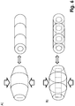
- Fig. 4 shows an external view of a urinary bladder prosthesis according to the invention ( Fig. 4a ) and a lateral section through the middle of the imaged urinary bladder prosthesis.
- the tubular liquid container (1) which has two lateral openings (2) for the inlet of liquid and in the middle two openings (3) for the discharge of liquid.
- the openings (3) are offset by about 90 ° to each other ( Fig. 4a ). This is also on the side cut up Fig. 4b to recognize.
- the wall of the liquid container (1) consists of two layers of material, one of which forms the inner wall (5) and one the outer wall (4) ( Fig. 4b ).
- the urinary bladder prosthesis is tube-shaped with a capacity of about 500 ml designed and has after implantation and connection with two artificial ureters a U-shaped ( Fig. 4 a) ,
- the wall of the liquid container consists of at least two intimately connected material layers, the inner layer forming the inner wall (5) and the outer layer, the outer wall (4). Possibly. Further material layers (8) may be present ( Fig. 5 ).
- the inner wall (5) of the liquid container (1) and the outer wall (4) of the liquid container (1) are made of different materials.
- the inner wall (5) of the liquid container (1) is chemically inert, smooth and made of silicone.
- the outer wall (4) is bioinert and consists of polyethylene terephthalate (PET), preferably Dacron ® .
- the openings (2, 3) of a liquid container are stabilized.
- a check valve is arranged (not shown).
- Embodiments of the openings (2, 3) of urinary bladder prostheses according to the invention are shown in FIG Fig. 5 without limiting the possibilities to these variants.
- the openings (2, 3) are preferably designed conical.
- the openings (2, 3) are designed so that they are suitable for fastening valve and / or hose elements. This is preferably done by at least one groove in the opening (2, 3).
- Fig. 5 a shows a stabilization by a ring (6), which is completely embedded in the inner material layer (5).
- Fig. 5b shows a stabilization by a ring structure (6), which is embedded in the inner material layer and in the material of a groove is embedded.
- Fig. 5c shows a stabilization by a ring (6), which is embedded in a stabilizing material layer (7).
- Fig. 5 d shows a stabilization by a ring (6), which is embedded in a stabilized ring structure (9), wherein the ring structure (9) in a material layer (8) is inserted, which is preferably not the outer wall (4) of the liquid container.
- the urinary bladder prosthesis is implanted subcutaneously in a patient and is used to replace the original urinary bladder.
- the openings (2) are connected to two artificial ureters, which are also implanted subcutaneously and serve to drain the urine from the kidneys.
- the urine is introduced from the kidneys via the artificial ureters via the openings (2) in the liquid container (1).
- Check valves are mounted on the ports to prevent urine from the fluid reservoir (1) from being returned to the artificial urethra (which is connected to the fluid reservoir (1) via the check valves and thus to the kidneys.
- the entry of the liquid can be carried out only in the direction of the liquid container (1).
- the other opening (2) is sealed with a blind plug and the outer wall of the liquid container (1) is sutured to the outer material of the blind plug.
- the wall of the liquid container (1) unfolds, so that the urinary bladder prosthesis is tubular in the filled state.
- the emptying of the urinary bladder prosthesis via one of the openings (3) is effected by preferably manually opening the valve at the opening (3).
- Exemplary valves are catheterizable valves which are manually opened by inserting a catheter.
- Other suitable valves are pressure-opening valves, which are opened by pressure and close automatically when pressure decreases.
- a male patient with a still existing urethra is implanted with a urinary bladder prosthesis according to the invention.
- the opening (3) points in the caudal direction. This allows the connection of an artificial urethra to the opening (3), which is implanted subcutaneously and perineally in the original urethra.
- a self-closing pressure-opening valve is placed, which is placed within the penile shaft. By compressing the penile shaft by the patient, the opening of the valve and the urine is discharged from the urinary bladder prosthesis. When the pressure drops, the valve closes automatically.
- the structure and function mechanism of a manually operable pressure port valve with longitudinal slot is in Fig. 6 shown.
- the piston-shaped valve comprises elastic closure pads made of a chemically inert plastic, in particular silicone, which seal tight in the unmanipulated state.
- the closure pads are opened to a nearly circular opening so that the urine can be discharged (shown on the left in the figure). After completion of the compression closing the return to their elastic basic shape closing pad automatically. An unwanted discharge of the urine is not possible in this state.
- a urinary bladder prosthesis according to the invention is implanted from a female patient with a defective urethra.
- the opening (3) points in the ventral direction. This allows the discharge by a catheterizable valve connected to the opening (3), which is implanted, for example, in such a way that the catheterization can take place via the navel.
- Subcutaneous implantation can advantageously replace both the urinary bladder prosthesis and individual parts thereof in a simple operation in the case of defects.
Description
Die Erfindung betrifft eine Harnblasenprothese für die subkutane Implantation, welche eine kontinente Harnableitung ermöglicht. Die Erfindung findet ihre Anwendung in der Medizin als Ersatz der Harnblase, welche krankheitsbedingt oder aufgrund von Zerstörungen entfernt wurde oder funktionsunfähig ist.The invention relates to a urinary bladder prosthesis for the subcutaneous implantation, which allows a continent urinary diversion. The invention finds its application in medicine as a replacement for the bladder, which has been removed due to disease or due to destruction or is inoperative.
Krankheitsbedingt kann es erforderlich sein, eine totale Entfernung der Harnblase vorzunehmen. Dies ist insbesondere bei Krebserkrankungen im kleinen Becken oder im Bauchraum der Fall. Oft werden Tumore dort erst in einem Zustand entdeckt, in dem sie fortgeschritten und daher nicht mehr problemlos zu entfernen sind. In solchen Fällen sind größere Operationen und Nachbestrahlungen oder Mehrfachoperationen unausweichlich, um ein erneutes Tumorwachstum zu stoppen oder zumindest zu verzögern. Liegen diese Krebsgeschwüre im Bereich des kleinen Beckens vor, z. B. bei Tumoren der Gebärmutter, der Prostata oder des unteren Darmes, sind oft auch die Harnleiter und die Harnblase betroffen.Due to illness, it may be necessary to perform a total removal of the bladder. This is especially the case in small pelvic or abdominal cancers. Often tumors are only discovered there in a state in which they are advanced and therefore no longer easy to remove. In such cases, major surgeries and post-radiation or multiple surgeries are inevitable to stop or at least delay retum growth. If these cancerous tumors in the area of the small pelvis, z. In tumors of the uterus, prostate or lower intestine, the ureters and bladder are often affected.
Harnleiter sind empfindliche gefäßähnliche Strukturen, welche im hinteren Bauchraum von den Nieren zur Harnblase verlaufen. Die Harnleiter können durch einen wachsenden Tumor gedrückt oder auch zerstört werden. Nach größeren Krebsoperationen oder Strahlenbehandlungen besteht außerdem die Gefahr, dass die Harnleiter durch Narbengewebe verengt werden, so dass sie den Urin nicht mehr adäquat in die Harnblase ableiten können.Ureters are delicate vessel-like structures that run from the kidneys to the bladder in the posterior abdomen. The ureters may be pushed or destroyed by a growing tumor. In addition, after major cancer surgery or radiation treatments, there is a risk that the ureters will be narrowed by scar tissue, so that they can no longer adequately discharge the urine into the bladder.
Eine totale Entfernung der Harnblase ist beispielsweise bei Tumoren erforderlich, welche von der Harnblase selbst ausgehen oder bei Tumoren der umgebenden Organe wie insbesondere Darm, Gebärmutter oder Scheide, bei denen bereits eine Invasion in die Harnblase erfolgte.Total removal of the urinary bladder is required, for example, in tumors originating from the bladder itself or in tumors of the surrounding organs such as, in particular, the intestine, uterus or vagina, which have already undergone invasion into the bladder.
In Fällen, bei denen ausschließlich die Harnblase von der Erkrankung betroffen ist, wird die originäre Harnblase entweder durch autologe, aus der Darmkontinuität ausgeschaltete Darmbestandteile ersetzt, oder ein ausgeschaltetes Darmsegment in die Haut als inkontinentes Urostoma implantiert. Ersteres Verfahren stellt als kontinente Versorgungsvariante an den betroffenen Patienten relativ klar formulierte Anforderungen. Es müssen tumorchirurgische sowie anatomische Voraussetzungen erfüllt sein. Vor-oder Nachbehandlungen, wie Strahlentherapien oder erneute chirurgische Eingriffe im Neoblasen-Operationsgebiet limitieren dieses OP-Verfahren. In den Fällen mit fortgeschrittenen Tumorbefunden oder auch der Befall von Nachbarorganen oder -strukturen sind orthotope Harnblasenersatzoperationen wie oben beschrieben ebenfalls kein Standard. Dies trifft auch für Tumorentitäten anderer Fachrichtungen, wie der Chirurgie oder Gynäkologie mit Harnblaseninfiltration zu. Auch hier sind nur inkontinente Harnableitungsverfahren möglich.In cases where only the urinary bladder is affected by the disease, the original urinary bladder is either replaced by autologous intestinal components that have been eliminated from the intestinal continuity, or a switched-off intestinal segment is implanted into the skin as an incontinent urostoma. The first method, as a continent supply variant, places relatively clearly formulated requirements on the patients concerned. It must be met tumor-surgical and anatomical conditions. Pre- or post-treatments, such as radiotherapy or new surgical procedures in the neobladder operation area limit this surgical procedure. In cases with advanced tumor findings or infestation of neighboring organs or structures, orthotopic urinary bladder replacement surgery as described above is also not standard. This is also true for Tumor entities of other disciplines, such as surgery or gynecology with bladder infiltration too. Again, only incontinent urinary diversion procedures are possible.
In diesen Fällen werden nach einer Totalentfernung der Harnblase bisher Harnableitungen implantiert, die mit extrakorporalen Auffangsystemen verbunden sind und den Harn inkontinent ableiten (z. B. perkutane Nephrostomien oder Urinstoma mit Auffangbeuteln). Dies bedeutet eine schwerwiegende Einschränkung der Lebensqualität der Patienten. Die regelmäßig und kurzfristig zu erneuernden Ableitungs- und Auffangsysteme bedeuten hohen Aufwand und Kosten.In these cases, after a total removal of the urinary bladder, urinary diversions have been implanted, which are connected to extracorporeal collecting systems and discharge the urine incontinently (eg percutaneous nephrostomies or urinaloma with collecting bags). This means a serious reduction in the quality of life of patients. The drainage and collection systems to be renewed regularly and at short notice mean high costs and effort.
Eine Harnblasenprothese, welche bei einer einfachen Anwendung einen kontinenten Ablauf ermöglicht, kann diese Nachteile überwinden.A urinary bladder prosthesis, which allows for a continual procedure in a simple application, can overcome these disadvantages.
Es sind Lösungen bekannt, eine künstliche Harnblase bereitzustellen, welche an die natürlichen Harnleiter und Harnröhre angeschlossen wird.Solutions are known to provide an artificial bladder which is connected to the natural urethra and urethra.
Problematisch bei den in
Weiter sind Lösungen bekannt, eine künstliche Harnblase bereitzustellen, welche an künstliche Harnleiter angeschlossen werden soll.Furthermore, solutions are known to provide an artificial bladder, which is to be connected to artificial ureters.
Ein ähnlicher Lösungsansatz wird durch
Die vorstehend beschriebenen Lösungen erfordern die Implantation einer künstlichen Harnblase in den unteren Bauchraum, genau an der Stelle, an der sich die originäre Harnblase befand. Beim Entfernen der Harnblase wird die Mitentfernung des unteren Bauchfells notwendig, so dass sich keine getrennten Kompartimente (unterer Bauchraum - Bauchraum) erhalten lassen. Dies führt dazu, dass die in den Bauchraum eingesetzten artifiziellen Systeme prinzipiell Kontakt mit den sensiblen Organen des Bauchraumes haben. Revisionseingriffe bei technischen Störungen von Harnblasenimplantaten, welche in den Bauchraum implantiert wurden, sind mit hohen Risiken für den Patienten behaftet.The solutions described above require the implantation of an artificial bladder into the lower abdomen, just where the original bladder was. Removal of the bladder necessitates the removal of the lower peritoneum so that no separate compartments (lower abdominal cavity) can be obtained. This leads to the fact that the artificial systems used in the abdominal area in principle have contact with the sensitive organs of the abdomen. Revision surgery for technical disorders of urinary bladder implants that have been implanted in the abdomen are associated with high risks for the patient.
Ein weiterer Nachteil an den vorbekannten Lösungen ist, dass das Ablassen des Harns hohe technische Anforderungen an die betroffenen Patienten stellt und daher für einen Großteil der Patientengruppe nicht bedienbar ist.Another disadvantage of the previously known solutions is that the draining of the urine places high technical demands on the patients concerned and therefore can not be operated for the majority of the patient group.
Das Reservoir ist in
Der durch das Entleeren der Harnblasenprothese erzeugte negative Druck innerhalb des Reservoirs verhindert einen Rückfluss des Harns zu den Nieren, so dass keine komplexen Rückschlagventile an der Verbindung von künstlichen Harnleitern und Reservoir angebracht sind. Durch die in
Die Gestaltung des künstlichen Harnröhrenschließmuskels inmitten des rohrförmigen Elements für die künstliche Harnröhre und der Implantation vor dem Schambein soll ggf. eine Kompression der künstlichen Harnröhre erlauben. Die Erreichbarkeit des Harnröhrenschließmuskels ist hier insbesondere bei adipösen Patienten erschwert, so dass Bedarf an weiteren Entleerungsvarianten besteht, um subkutan implantierbare Harnblasenprothesen universell einzusetzen. Weiter muss unbedingt verhindert werden, dass ein Rückfluss von Harn zu den Nieren möglich ist.The design of the artificial urethral sphincter in the midst of the tubular element for the artificial urethra and the implantation in front of the pubic bone should possibly allow a compression of the artificial urethra. The accessibility of the urethral sphincter is particularly difficult in obese patients, so that there is a need for further emptying variants to use subcutaneously implantable urinary bladder prostheses universally. Furthermore, it must be absolutely prevented that a return of urine to the kidneys is possible.
Die in
Aufgabe der Erfindung ist es eine Harnblasenprothese bereitzustellen, die für die subkutane Implantation geeignet ist und die in einer einfachen Bedienung eine kontinente Harnableitung ermöglicht. Weiterhin soll die Harnblasenprothese so gestaltet sein, dass sie im Rahmen einer minimalinvasiven Operation implantiert werden kann und einfach operativ ausgetauscht werden kann.The object of the invention is to provide a urinary bladder prosthesis which is suitable for subcutaneous implantation and which permits continual removal of urine in a simple operation. Furthermore, the urinary bladder prosthesis should be designed so that it can be implanted as part of a minimally invasive surgery and can be easily replaced surgically.
Die Aufgabe wird erfindungsgemäß gelöst durch eine Harnblasenprothese mit den Merkmalen nach Anspruch 1 sowie einen Bausatz zur Herstellung einer Harnblasenprothese nach Anspruch 9. Weitere Ausgestaltungen enthalten die Unteransprüche 2 bis 8 bzw. 10 bis 12.The object is achieved by a urinary bladder prosthesis with the features of
Die Harnblasenprothese für die subkutane Implantation umfasst einen flexiblen, im Wesentlichen schlauchförmigen Flüssigkeitsbehälter, dessen Wand mindestens zwei miteinander verbundene Materialschichten enthält, der eine vordere und eine hintere Seite besitzt, von denen mindestens die vordere Seite stabilisierende Elemente aufweist, der an den seitlichen Enden zwei Öffnungen für den Zulauf von Flüssigkeit aufweist und der mindestens eine Öffnung zum Abfluss von Flüssigkeit aufweist. Dabei sind die Öffnungen stabilisiert oder starr dergestalt ausgebildet, dass sie zur Befestigung von Ventil- oder Schlauchelementen geeignet sind. An den Öffnungen an den seitlichen Enden des Flüssigkeitsbehälters ist jeweils ein Rückschlagventil angeordnet oder es ist an einer der Öffnungen ein Rückschlagventil angeordnet und die andere Öffnung ist mit einem Verschlussstopfen verschlossen. Die äußere Schicht der Flüssigkeitsbehälterwand besteht aus bioinertem Material, vorzugsweise einem organischen Polymer, insbesondere Polyester, vorzugsweise Polyethylenterephthalat (PET), bevorzugt Dacron®. Die innere Schicht der Flüssigkeitsbehälterwand ist glatt und besteht aus einem chemisch inerten Material, vorzugsweise aus einem organischen Polymer, insbesondere Silikon. Erfindungsgemäß sind die Materialschichten der Wand des Flüssigkeitsbehälters miteinander stoffschlüssig verbunden. Zur kontinenten Entleerung der Harnblasenprothese ist an mindestens einer der Öffnungen zum Abfluss von Flüssigkeit ein manuell betätigbares Ventilelement oder ein Schlauchelement, welches ein manuell betätigbares Ventil enthält, angeordnet. Durch manuelle Betätigung des Ventils wird ein kontinentes Ableiten von Flüssigkeit aus dem Flüssigkeitsbehälter gewährleistet. Die mechanische Stabilisierung der Behälterwand und das manuell zu öffnende Ventil verhindern eine unkontrollierte Entleerung der Harnblasenprothese bei versehentlichem Druck auf den Flüssigkeitsbehälter. Da die Harnblasenprothese für die subkutane Implantation ausgestaltet ist, ist eine Bedienung über manuell betätigbare Ventile sichergestellt und ein einfacher operativer Austausch von Bestandteilen der Harnblasenprothese minimalinvasiv möglich.The urinary bladder prosthesis for subcutaneous implantation comprises a flexible, substantially tubular fluid container, the wall of which contains at least two interconnected layers of material having front and rear sides, at least the front side of which has stabilizing elements, and two openings at the lateral ends for the inlet of liquid and having at least one opening for the outflow of liquid. The openings are stabilized or rigidly designed such that they Attachment of valve or hose elements are suitable. At the openings at the lateral ends of the liquid container in each case a check valve is arranged or it is arranged at one of the openings, a check valve and the other opening is closed with a sealing plug. The outer layer of the liquid container wall is made of bio-inert material, preferably an organic polymer, in particular polyester, preferably polyethylene terephthalate (PET), preferably Dacron® . The inner layer of the liquid container wall is smooth and consists of a chemically inert material, preferably of an organic polymer, in particular silicone. According to the invention, the material layers of the wall of the liquid container are connected to one another in a material-locking manner. For continual emptying of the urinary bladder prosthesis, a manually operable valve element or a tube element which contains a manually operable valve is arranged on at least one of the openings for the outflow of fluid. By manual operation of the valve, a continental discharge of liquid from the liquid container is ensured. The mechanical stabilization of the container wall and the manually-open valve prevent uncontrolled emptying of the urinary bladder prosthesis in case of accidental pressure on the liquid container. Since the urinary bladder prosthesis is designed for subcutaneous implantation, an operation via manually operable valves is ensured and a simple surgical exchange of components of the urinary bladder prosthesis is possible in a minimally invasive manner.
Der Flüssigkeitsbehälter der erfindungsgemäßen Harnblasenprothese besitzt eine vordere und eine hintere Seite, von denen mindestens die vordere Seite stabilisierende Elemente aufweist. Weiter weist der Flüssigkeitsbehälter an den seitlichen Enden eine oder zwei, vorzugsweise zwei, Öffnungen für den Zulauf von Flüssigkeit und mindestens eine, vorzugsweise eine oder zwei, Öffnungen zum Abfluss von Flüssigkeit auf.The liquid container of the urinary bladder prosthesis according to the invention has a front and a back side, of which at least the front side has stabilizing elements. Further, the liquid container at the lateral ends one or two, preferably two, openings for the supply of liquid and at least one, preferably one or two, openings for the outflow of liquid.
Die Öffnungen sind stabilisiert oder starr dergestalt ausgebildet, dass sie zur Befestigung von Ventil- oder Schlauchelementen geeignet sind.The openings are stabilized or rigidly designed such that they are suitable for fastening valve or hose elements.
Um eine subkutane Verträglichkeit der erfindungsgemäßen Harnblasenprothese sicherzustellen, ist der Flüssigkeitsbehälter flexibel gestaltet, damit die subkutane Verbringung nach instrumenteller Expandierung und Etablierung des notwendigen vorzugsweise suprasymphysären Hohlraumes einfach möglich ist. Unter "flexibel" im erfindungsgemäßen Sinn ist zu verstehen, dass der Flüssigkeitsbehälter elastisch und biegsam ist und nach Wegfall einer Krafteinwirkung in die Ursprungsform zurückkehren kann. Bevorzugt ist der Flüssigkeitsbehälter durch Guss- oder Sprayverfahren hergestellt.In order to ensure a subcutaneous compatibility of the urinary bladder prosthesis according to the invention, the liquid container is designed to be flexible, so that the subcutaneous movement after instrumental expansion and establishment of the necessary preferably suprasymphysäre cavity is easily possible. Under "flexible" in the sense of the invention is to be understood that the liquid container is elastic and flexible and can return to the original form after elimination of a force. Preferably, the liquid container is produced by casting or spraying.
Der Flüssigkeitsbehälter eignet sich für die subkutane Implantation. Er besitzt längsseitig zwei Seiten, von denen eine nach der Implantation zur Körperaußenseite zeigt (hierin auch als vordere Seite bezeichnet) und die andere zu den inneren Organen gerichtet ist (hierin auch als hintere Seite bezeichnet). Um die entsprechenden mechanischen Anforderungen nach der Implantation zu erfüllen, enthält mindestens eine der Seiten (die nach der Implantation vordere Seite) stabilisierende Elemente, die in die Wand des Flüssigkeitsbehälters eingearbeitet sind. Ggf. kann die gesamte Wand des Flüssigkeitsbehälters (vordere und hintere Seite) stabilisierende Elemente aufweisen.The liquid container is suitable for subcutaneous implantation. It has two longitudinal sides, one of which faces the outside of the body after implantation (also referred to herein as the front side) and the other one faces the internal organs (also referred to herein as the posterior side). In order to meet the corresponding mechanical requirements after implantation, at least one of the sides (the front side after implantation) contains stabilizing elements incorporated in the wall of the liquid container. Possibly. the entire wall of the liquid container (front and rear side) may have stabilizing elements.
Stabilisierende Elemente bewirken, dass das Material oder Werkstoff in ausreichendem Maße biegsam ist, um für die subkutane Implantation geeignet zu sein, gleichwohl gegen äußere Krafteinwirkung in erforderlichem Maße druckstabil ist, so dass keine Zerstörung oder plastische Verformung durch üblicherweise auftretende Krafteinflüsse (z. B. Niesen, Husten, Schlag auf den Bauch) möglich ist. Vorzugsweise werden mechanische Stabilisierungen eingesetzt, um die Druckstabilität zu gewährleisten.Stabilizing elements cause the material or material to be sufficiently flexible to be suitable for subcutaneous implantation, yet being pressure stable to the extent necessary against external force, so that no destruction or plastic deformation by normally occurring force influences (eg. Sneezing, coughing, blow on the stomach) is possible. Preferably, mechanical stabilizations are used to ensure the pressure stability.
Dadurch ist eine bestimmte Unempfindlichkeit der Harnblasenprothese gegen mechanische Einflüsse von außen gewährleistet. Andererseits wird ein problemloses Entleeren des Flüssigkeitsbehälters der erfindungsgemäßen Harnblasenprothese ermöglicht.This ensures a certain insensitivity of the urinary bladder prosthesis against external mechanical influences. On the other hand, a trouble-free emptying of the liquid container of the urinary bladder prosthesis according to the invention is made possible.
Mechanische Stabilisierungen werden vorzugsweise durch Gerüststrukturen (auch als Stützstrukturen bezeichnet) gewährleistet. Die Gerüststrukturen sind bevorzugt als Spirale, Feder, Rippen oder zylinder- oder quaderförmige Verbindungsstücke (z. B. Stäbe) ausgestaltet. Sie können sowohl aus massivem Material als auch aus Gitter- oder Netzstrukturen bestehen. Vorzugsweise sind die Gerüststrukturen so ausgestaltet, dass diese gleichmäßig verteilt oder durchgehend über die Länge der Harnblasenprothese angeordnet sind. Bevorzugte Materialien für Gerüststrukturen sind Metalle und/oder Polymere. Bevorzugte Stützstrukturen sind Federmetallskelette. Alternativ oder ergänzend zu Gerüststrukturen werden Stabilisierungen durch stabilisierende Elemente vorzugsweise durch Erhöhung der Materialdicke (Dicke der Flüssigkeitsbehälterwand) oder als Rippenskelett aus dem Grundmaterial gewährleistet und/oder indem die Behälterwand mindestens eine weitere Materialschicht als Zwischenschicht zwischen der äußeren und inneren Materialschicht als stabilisierendes Element enthält.Mechanical stabilizations are preferably ensured by framework structures (also referred to as support structures). The framework structures are preferably designed as a spiral, spring, ribs or cylindrical or cuboidal connecting pieces (eg rods). They can consist of solid material as well as grid or net structures. Preferably, the framework structures are designed so that they are uniformly distributed or arranged throughout the length of the urinary bladder prosthesis. Preferred materials for framework structures are metals and / or polymers. Preferred support structures are spring metal skeletons. As an alternative or in addition to framework structures, stabilizations by stabilizing elements are preferably ensured by increasing the material thickness (thickness of the liquid container wall) or as rib skeleton from the base material and / or by the container wall containing at least one further material layer as intermediate layer between the outer and inner material layer as stabilizing element.
Das Material des Flüssigkeitsbehälters besitzt Memory-Eigenschaften, d. h. dass der Flüssigkeitsbehälter bei nachlassender Krafteinwirkung seine ursprüngliche Gestalt wieder annimmt. Dies ist für die Entleerung der erfindungsgemäßen Harnblasenprothese wichtig, da bei der Entleerung keine Luft in die Harnblasenprothese einströmen soll. Die vordere und hintere Wand des Flüssigkeitsbehälters nähern sich beim Entleeren der Harnblasenprothese an, beim Befüllen durch Zufluss von Harn entfaltet sich der Flüssigkeitsbehälter aufgrund der Memory-Eigenschaften des Materials ohne großen Druckaufwand.The material of the liquid container has memory properties, ie that the liquid container assumes its original shape with decreasing force. This is important for the emptying of the urinary bladder prosthesis according to the invention, since during emptying no air should flow into the urinary bladder prosthesis. The front and rear walls of the liquid container approach when emptying the urinary bladder prosthesis, during filling by Inflow of urine, the liquid container unfolds due to the memory properties of the material without much pressure.
Die Wand des Flüssigkeitsbehälters enthält mindestens zwei miteinander innig verbundene Materialschichten (insbesondere stoffschlüssig, vorzugsweise durch Verkleben der Materialien der einzelnen Schichten), von denen die innere Schicht die Innenwand des Flüssigkeitsbehälters und die äußere Schicht die Außenwand des Flüssigkeitsbehälters bildet. Die Innenwand des Flüssigkeitsbehälters und die Außenwand des Flüssigkeitsbehälters bestehen vorzugsweise aus unterschiedlichen Materialien.The wall of the liquid container contains at least two intimately connected material layers (in particular materially, preferably by bonding the materials of the individual layers), of which the inner layer forms the inner wall of the liquid container and the outer layer forms the outer wall of the liquid container. The inner wall of the liquid container and the outer wall of the liquid container are preferably made of different materials.
Die Innenwand des Flüssigkeitsbehälters (auch als "Behälterinnenwand" bezeichnet) besteht aus chemisch inertem Material. Unter "chemisch inert" in diesem Zusammenhang sind solche Materialien zu verstehen, die nach der Implantation einer erfindungsgemäßen Harnblasenprothese nicht oder nur in verschwindend geringem Maße mit potentiellen Reaktionspartnern reagieren. Dies bedeutet, dass Materialien der Behälterinnenwand nicht oder nur in verschwindend geringem Maße mit Bestandteilen des Harns reagieren. Die Behälterinnenwand ist glatt, d. h. sie weist vorzugsweise keine Löcher, Risse, Erhebungen oder Unebenheiten auf. Dies ist notwendig, um feste Ablagerungen von Harn an prädestinierten Stellen der Innenwand des Flüssigkeitsbehälters zu vermeiden. Vorzugsweise besteht die Behälterinnenwand aus einem flexiblen Polymer, welches bevorzugt synthetisch oder halbsynthetisch ist. Dieses ist vorzugsweise so ausgewählt, dass es eine niedrige Oberflächenspannung besitzt, so dass es nicht an sich selbst haftet. Besonders bevorzugte Materialien für die Innenwand des Flüssigkeitsbehälters (bzw. die innere Schicht der Flüssigkeitsbehälterwand) sind Silikone (Poly(organo)siloxane).The inner wall of the liquid container (also referred to as "container inner wall") consists of chemically inert material. By "chemically inert" in this context, those materials are to be understood that react after implantation of a urinary bladder prosthesis according to the invention or only to a negligible degree with potential reactants. This means that materials of the inner wall of the container do not or only to a small extent react with components of the urine. The container inner wall is smooth, d. H. it preferably has no holes, cracks, bumps or bumps. This is necessary to avoid solid deposits of urine at predestined points of the inner wall of the liquid container. Preferably, the container inner wall is made of a flexible polymer, which is preferably synthetic or semisynthetic. This is preferably selected to have a low surface tension so that it does not adhere to itself. Particularly preferred materials for the inner wall of the liquid container (or the inner layer of the liquid container wall) are silicones (poly (organo) siloxanes).
Die Außenwand des Flüssigkeitsbehälters besteht aus einem bioinerten Material. Unter "bioinert" in diesem Zusammenhang sind solche Materialien zu verstehen, die keine schädigende und immunogene Wirkung auf den menschlichen Körper ausüben und nicht mit umgebenden Substanzen reagieren und dadurch beispielsweise korrodieren. Bioinerte Materialien führen nach der Implantation zu praktisch keiner chemischen und/oder biologischen Wechselwirkung zwischen Material und dem umliegenden Gewebe. Es werden praktisch keine toxischen Substanzen freigesetzt. Vorzugsweise besteht die Behälteraußenwand aus mindestens einem (vorzugsweise organischen) Polymer, welches bevorzugt halbsynthetisch oder synthetisch ist. Besonders bevorzugte Materialien für die Außenwand des Flüssigkeitsbehälters (bzw. die äußere Schicht der Flüssigkeitsbehälterwand) sind Polyethylenterephthalate (PET), ganz besonders bevorzugt Dacron® , Diolen®, Tergal®, Terylene® oder Trevira®. Vorzugsweise besitzt die Außenwand eine raue Oberfläche. In einer Ausgestaltung der Erfindung ist die Außenwand des Flüssigkeitsbehälters aus einer durchgehenden Ummantelung aus einem bioinerten Kunststoff, bevorzugt PET, dargestellt, welche als Überzug auf dem innen liegenden Material oder den innen liegenden Materialschichten vorliegt. So sollen Abstoßungs- und Entzündungsreaktionen verhindert werden, die nur aufgrund einer immunologischen Antwort auf das Oberflächenmaterial erfolgen.The outer wall of the liquid container is made of a bio-inert material. By "bioinert" in this context are meant those materials which do not exert any damaging and immunogenic effect on the human body and do not react with surrounding substances and thereby corrode, for example. Bioinert materials lead after implantation to virtually no chemical and / or biological interaction between the material and the surrounding tissue. Virtually no toxic substances are released. Preferably, the container outer wall consists of at least one (preferably organic) polymer, which is preferably semi-synthetic or synthetic. Particularly preferred materials for the outer wall of the liquid container (or the outer layer of the fluid container wall) are polyethylene terephthalate (PET), very particularly preferably Dacron ®, ® diols, Tergal ®, Terylene or Trevira ® ®. Preferably, the outer wall has a rough surface. In one embodiment of the invention, the outer wall of the liquid container from a continuous sheath of a bio-inert plastic, preferably PET, shown, which as a coating on the inside Material or the internal material layers is present. Thus, rejection and inflammatory reactions are to be prevented, which take place only due to an immunological response to the surface material.
Der Flüssigkeitsbehälter weist eine Gestalt auf, die im Wesentlichen schlauchförmig ist und an den seitlichen Enden eine oder zwei, vorzugsweise zwei Öffnungen aufweist. Unter einer im Wesentlichen schlauchförmigen Form ist zu verstehen, dass der Flüssigkeitsbehälter mit einer rohrförmigen Gestalt ausgebildet ist, wobei der Innendurchmesser des Rohrs an der längsseitigen Behältermitte bevorzugt größer ist, als der Innendurchmesser an den seitlichen Enden. Der Flüssigkeitsbehälter weist vorzugsweise eine symmetrische, insbesondere achsensymmetrische Form auf. Alternativ dazu weist der Flüssigkeitsbehälter vorzugsweise die Form eines Kreisringsegments auf.The liquid container has a shape that is substantially tubular and has one or two, preferably two, openings at the lateral ends. By a substantially tubular shape is meant that the liquid container is formed in a tubular shape, wherein the inner diameter of the tube at the longitudinal side of the container is preferably larger than the inner diameter at the lateral ends. The liquid container preferably has a symmetrical, in particular axisymmetric shape. Alternatively, the liquid container preferably has the shape of a circular ring segment.
Die seitlichen Öffnungen des Flüssigkeitsbehälters dienen dem Zulauf von Flüssigkeit. Das Material des Flüssigkeitsbehälters ist an den Öffnungen stabilisiert oder starr. Bevorzugt sind die Öffnungen mit einer konischen Form ausgestaltet.The lateral openings of the liquid container are used for the supply of liquid. The material of the liquid container is stabilized at the openings or rigid. Preferably, the openings are configured with a conical shape.
Weiter enthält der Flüssigkeitsbehälter mindestens eine, vorzugsweise mindestens eine, vorzugsweise eine oder zwei, Öffnungen zum Abfluss von Flüssigkeit (hierin auch als Abflussöffnungen bezeichnet). Diese sind vorzugsweise in der Mitte des Flüssigkeitsbehälters zwischen den endständigen Öffnungen angeordnet. Besonders bevorzugt sind zwei Öffnungen in der Mitte des Flüssigkeitsbehälters angeordnet, wobei diese zueinander in einem Winkel von etwa 90° versetzt sind. Dies hat den Hintergrund, dass bei Implantation je nach Erfordernis des Patienten der Flüssigkeitsbehälter mit einer Öffnung in die benötigte Richtung (z. B. kaudal oder ventral) angebracht wird. Die andere Öffnung wird in diesem Fall vorzugsweise durch einen Blindstopfen verschlossen.Furthermore, the liquid container contains at least one, preferably at least one, preferably one or two, openings for the outflow of liquid (also referred to herein as discharge openings). These are preferably arranged in the middle of the liquid container between the terminal openings. Particularly preferably, two openings are arranged in the middle of the liquid container, wherein these are offset from each other at an angle of approximately 90 °. This has the background that, when implanted, the liquid container is attached with an opening in the required direction (eg, caudal or ventral) as required by the patient. The other opening is preferably closed in this case by a blind plug.
Sowohl die seitlichen Öffnungen als auch die Öffnungen, die für den Ablauf von Flüssigkeit vorgesehen sind, sind so ausgestaltet, dass sie zur Befestigung von Ventil- oder Schlauchelementen geeignet sind. Dies wird durch Stabilisierung der Öffnungen bewerkstelligt, indem vorzugsweise Metallstrukturen (bevorzugt als Ring) oder andere stabilisierte Materialien (bevorzugt stabilisierende Elemente) für die Ausgestaltung der Öffnungen verwendet werden. Bevorzugte Varianten zur Stabilisierung der Öffnungen liegen in der Auswahl stabilisierter Materialien in Kombination mit einer erhöhten Dicke der Wand des Flüssigkeitsbehälters und dem Einbau von Stützstrukturen, vorzugsweise metallischer Stützstrukturen. Bevorzugt werden die Stützstrukturen in Guss- oder Sprayverfahren in den Flüssigkeitsbehälter eingearbeitet.Both the lateral openings and the openings provided for the drainage of liquid are designed so that they are suitable for fastening valve or hose elements. This is accomplished by stabilizing the apertures by preferably using metal structures (preferably as a ring) or other stabilized materials (preferably stabilizing elements) for the design of the apertures. Preferred variants for stabilizing the openings are the selection of stabilized materials in combination with an increased thickness of the wall of the liquid container and the installation of support structures, preferably metallic support structures. Preferably, the support structures are incorporated into the liquid container in casting or spray processes.
An den Öffnungen können Ventil- und Schlauchelemente befestigt werden. Ventilelemente werden direkt an einer Öffnung der erfindungsgemäßen Harnblasenprothese vorzugsweise über Schlauchsteckverbindungen befestigt. Unter "Schlauchelementen" ist hierin ein separater Schlauch oder auch ein Schlauch mit einem daran angeordneten Ventil zu verstehen.Valve and hose elements can be attached to the openings. Valve elements are attached directly to an opening of the urinary bladder prosthesis according to the invention preferably via hose connectors. By "hose members" herein is meant a separate hose or hose having a valve disposed thereon.
An mindestens einer der seitlichen Öffnungen des Flüssigkeitsbehälters der Harnblasenprothese ist ein Rückschlagventil angeordnet. Rückschlagventile dienen zur Verhinderung der Drucktransmission in die Nieren beim Entleeren des Flüssigkeitsbehälters oder bei auf den Flüssigkeitsbehälter ausgeübtem Druck. Die Befestigung der Ventile wird vorzugsweise durch Schlauchsteckverbindungen bewerkstelligt. Rückschlagventile haben den Vorteil, dass der Rücktritt von Harn aus dem Inneren der Harnblasenprothese in die künstlichen Harnleiter verhindert wird. Als Rückschlagventile sind alle Ventile geeignet, die die Strömungsrichtung der Flüssigkeit (des Harns) so bestimmen, dass nur der Fluss von den Nieren zu dem Flüssigkeitsbehälter erfolgt. Der Durchgang des Harns in die entgegengesetzte Richtung (vom Flüssigkeitsbehälter zu den Nieren) wird durch Rückschlagventile selbsttätig gesperrt. Bevorzugt werden Flatterventile als Rückschlagventile eingesetzt. Flatterventile öffnen in Durchlassrichtung und schließen selbsttätig ohne sonstigen äußeren Antrieb, nur aufgrund von Druckunterschieden auf den beiden Seiten des Ventils. Flatterventile bestehen vorzugsweise aus elastischem Material, dessen Eigenschaften gleichzeitig das Schließen des Ventils sicherstellt und dennoch so steif ist, dass die Ventilfunktion sichergestellt wird. Die Rückschlagventile bestehen bevorzugt aus inertem Kunststoff, insbesondere Silikon.At least one of the lateral openings of the liquid container of the urinary bladder prosthesis, a check valve is arranged. Check valves are used to prevent pressure transmission to the kidneys when emptying the fluid reservoir or when pressure is applied to the fluid reservoir. The attachment of the valves is preferably accomplished by hose connectors. Check valves have the advantage that the withdrawal of urine from the interior of the urinary bladder prosthesis is prevented in the artificial ureters. As check valves, all valves are suitable, which determine the flow direction of the liquid (the urine) so that only the flow from the kidneys to the liquid container takes place. The passage of the urine in the opposite direction (from the fluid reservoir to the kidneys) is automatically blocked by check valves. Fluttering valves are preferably used as check valves. Flutter valves open in the forward direction and close automatically without any other external drive, only due to pressure differences on the two sides of the valve. Flutter valves are preferably made of elastic material, whose properties at the same time ensures the closing of the valve and yet is so stiff that the valve function is ensured. The check valves are preferably made of inert plastic, in particular silicone.
Erfindungsgemäß ist an mindestens einer Abflussöffnung ein manuell betätigbares Ventilelement oder ein Schlauchelement, welches ein manuell betätigbares Ventil enthält, angeordnet. Für den Fall, dass der Flüssigkeitsbehälter zwei oder mehr Abflussöffnungen aufweist, sind die Öffnungen ohne Ventil- oder Schlauchelement vorzugsweise mit einem Blindstopfen verschlossen. Unter einem "Blindstopfen" ist im Sinne der Erfindung ein Verschlussstopfen zu verstehen, der vorzugsweise aus dem gleichen Material, wie der Flüssigkeitsbehälter besteht. Zumindest sind die Materialien der Innen- und Außenseite des Blindstopfens die gleichen, wie die Innen- und Außenseite des Flüssigkeitsbehälters. Der Blindstopfen ist bevorzugt so gestaltet, dass bei dem Verschluss der Öffnung keine Unebenheiten oder Lücken an Behälterinnenwand und Behälteraußenwand auftreten. Blindstopfen werden ggf. auch an einer der seitlichen Öffnungen des Flüssigkeitsbehälters angeordnet.According to the invention, a manually operable valve element or a hose element which contains a manually operable valve is arranged on at least one outflow opening. In the event that the liquid container has two or more discharge openings, the openings without valve or hose element are preferably closed with a blind plug. For the purposes of the invention, a "blind plug" is to be understood as a sealing plug which preferably consists of the same material as the liquid container. At a minimum, the materials of the inside and outside of the blind plug are the same as the inside and outside of the liquid container. The blind plug is preferably designed so that no unevenness or gaps in the container inner wall and container outer wall occur during the closure of the opening. If necessary, blind plugs are also arranged on one of the lateral openings of the liquid container.
Für den Fall, dass ein Ventil über ein Schlauchelement mit der Abflussöffnung des Flüssigkeitsbehälters verbunden ist, ist dieses Ventil vorzugsweise endständig am Schlauchelement angeordnet.In the event that a valve is connected via a hose element with the discharge opening of the liquid container, this valve is preferably arranged terminally on the hose member.
Die an den Abflussöffnungen befestigbaren Ventilkonstruktionen können verschiedenartig gestaltet sein. Sie sind vorzugsweise so ausgestaltet, dass eine manuelle Bedienung des Ventils durch den Patienten möglich ist. Dies geschieht bevorzugt durch ein durch manuellen Druck (auf das Ventil) zu öffnendes Ventil (hierin "Drucköffnungsventil") oder ein katheterisierbares Ventil. Das Ventil ist über die Abflussöffnung direkt oder über einen Schlauch, vorzugsweise über eine aus dem Stand der Technik bekannte künstliche Harnröhre, mit der erfindungsgemäßen Harnblasenprothese verbunden.The attachable to the drain openings valve designs can be designed differently. They are preferably designed so that a manual operation of the valve by the patient is possible. This is preferably done by a valve to be opened by manual pressure (on the valve) (herein "pressure port valve") or a catheterizable valve. The valve is connected to the urinary bladder prosthesis via the outflow opening directly or via a hose, preferably via an artificial urethra known from the prior art.
Um zu verhindern, dass die Harnblasenprothese bei Überfüllung durch den auftretenden Systemdruck in der Harnblasenprothese (analog zum Harnröhrenverschlussdruck im originären System) beschädigt und damit undicht wird oder, ist das Ventil vorzugsweise so ausgestaltet, dass es bei einem herrschenden Systemdruck, der den maximal zulässigen Systemdruck, für den die Harnblasenprothese ausgelegt ist, übersteigt, automatisch öffnet und den Ablauf von Flüssigkeit ermöglicht. Dadurch wird ein unkontrollierter Austritt von Harn innerhalb des Körpers verhindert.In order to prevent the urinary bladder prosthesis from being damaged and thus leaking when it is overfilled by the system pressure occurring in the urinary bladder prosthesis (analogous to the urethral closure pressure in the original system), the valve is preferably designed such that, at a prevailing system pressure, the maximum permissible system pressure for which the urinary bladder prosthesis is designed, exceeds, automatically opens and allows drainage of fluid. This prevents uncontrolled leakage of urine within the body.
In einer Ausgestaltung der Erfindung ist direkt an einer Abflussöffnung ein katheterisierbares Ventil angebracht. Die ggf. vorhandene zweite Abflussöffnung ist vorzugsweise mit einem Blindstopfen verschlossen.In one embodiment of the invention, a catheterizable valve is attached directly to a drain opening. The possibly existing second drain opening is preferably closed with a blanking plug.
Bevorzugt sind die manuell zu betätigenden Ventile selbstverschließend, insbesondere selbstverschließende katheterisierbare Ventile oder selbstverschließende Drucköffnungsventile. Selbstverschließende Ventile sind vorzugsweise aus elastischen Materialien hergestellt.The manually operated valves are preferably self-closing, in particular self-closing catheterisable valves or self-closing pressure-opening valves. Self-closing valves are preferably made of elastic materials.
Das selbstverschließende Drucköffnungsventil ist bevorzugt als Längsschlitz- oder Kreuzschlitzventil ausgestaltet und wird durch Druck von außen auf das Ventil geöffnet. Ein automatisches Schließen des Ventils erfolgt, wenn kein radialer Druck auf das Ventil ausgeübt wird. Kreuzschlitzventile haben zusätzlich den Vorteil, dass eine Öffnung in nahezu jeder Position erfolgen kann, ohne dass auf die Lage des Ventils geachtet werden muss. Bevorzugt ist das Längsschlitz- oder Kreuzschlitzventil als kolbenförmiges elastisches Segment ausgestaltet, welches mit Verschlusskissen oder Dichtungslippen ausgestattet ist und im Inneren den Längsschlitz oder Kreuzschlitz aufweist. Im nichtmanipulierten Zustand schließen die Verschlusskissen oder Dichtungslippen dicht ab und ein Ablauf von Flüssigkeit ist nicht möglich. Nach Zusammendrücken des kolbenförmigen Segments wird der Schlitz geöffnet und ein Ablauf von Flüssigkeit wird ermöglicht. Bei nachlassendem Druck verschließen sich die in ihre elastische Grundform zurückkehrenden Verschlusskissen oder Dichtungslippen selbsttätig.The self-closing pressure-opening valve is preferably designed as a longitudinal slot or Phillips valve and is opened by pressure from the outside to the valve. An automatic closing of the valve takes place when no radial pressure is exerted on the valve. Phillips valves have the additional advantage that an opening can be made in almost any position, without having to pay attention to the position of the valve. Preferably, the Längsschlitz- or Phillips valve is designed as a piston-shaped elastic segment, which is equipped with closure pad or sealing lips and having the longitudinal slot or Phillips inside. In the non-manipulated state close the sealing pads or sealing lips tight and a drain of liquid is not possible. After compressing the piston-shaped segment, the slot is opened and a drain of liquid is made possible. When the pressure is released, the closing cushions or sealing lips returning to their elastic basic shape close automatically.
Ein selbstverschließendes Drucköffnungsventil wird insbesondere in Verbindung mit einem Schlauchelement eingesetzt, welches mit dem Flüssigkeitsbehälter der Harnblasenprothese verbunden ist. Diese Ausgestaltung der Erfindung ist für die Anwendung bei männlichen Patienten besonders geeignet, wobei die Implantation des Schlauchelements in die originäre Harnröhre erfolgt und das Ventil am distalen Ende des Schlauchelements im Penisschaft platziert wird. Durch Zusammendrücken des Penisschaftes erfolgt eine Öffnung des Ventils und die Flüssigkeit wird aus der Harnblasenprothese abgeleitet. Bei nachlassendem Druck verschließt das Ventil selbsttätig.A self-closing pressure-opening valve is used in particular in connection with a hose element which is connected to the liquid container of the urinary bladder prosthesis. This embodiment of the invention is particularly for use in male patients wherein the implantation of the tubular element into the original urethra and the valve is placed at the distal end of the tubular element in the penile shaft. By compressing the penile shaft, the valve is opened and the fluid is discharged from the urinary bladder prosthesis. When the pressure drops, the valve closes automatically.
Das manuell betätigbare Ventil ist bevorzugt aus einem chemisch inerten Material, insbesondere Silikon hergestellt. Bei der Anwendung von Ventilen in Kombination mit Schlauchelementen sind Ventil mit Schlauchelement besonders bevorzugt einstückig ausgebildet. Auf diese Weise entfällt eine nachträgliche Verbindung der beiden Teile, die zu Unebenheiten und Ablagerungen von Bestandteilen des Harns führen kann.The manually operable valve is preferably made of a chemically inert material, in particular silicone. When using valves in combination with hose elements valve with hose element are particularly preferably formed in one piece. In this way, no subsequent connection of the two parts, which can lead to bumps and deposits of components of the urine.
In einer Ausgestaltung der erfindungsgemäßen Harnblasenprothese ist an einer Abflussöffnung ein Schlauchelement angebracht. Die ggf. vorhandene zweite Abflussöffnung ist vorzugsweise mit einem Blindstopfen verschlossen. Das Schlauchelement umfasst eine künstliche Harnröhre (künstliche Urethra) in Kombination mit einem Ventil, vorzugsweise einem Drucköffnungsventil, insbesondere ein selbstverschließendes Längsschlitz- oder Kreuzschlitzventil, welches endständig an der künstlichen Urethra angebracht ist. Künstliche Harnröhren sind aus dem Stand der Technik bekannt. Die künstliche Harnröhre ist mit einem Ende an der Abflussöffnung der Harnblasenprothese verbunden. Am anderen Ende der künstlichen Harnröhre befindet sich ein Ventil.In one embodiment of the urinary bladder prosthesis according to the invention, a hose element is attached to a drain opening. The possibly existing second drain opening is preferably closed with a blanking plug. The tube element comprises an artificial urethra (artificial urethra) in combination with a valve, preferably a pressure-opening valve, in particular a self-closing longitudinal slotted or phillips valve which is attached end-to-end to the artificial urethra. Artificial urethras are known in the art. The artificial urethra is connected at one end to the drainage port of the urinary bladder prosthesis. At the other end of the artificial urethra is a valve.
Alternativ zu bekannten künstlichen Harnröhren können beliebige andere Schlauchelemente an den Abflussöffnungen befestigt werden, die flexibel sind und deren Außenwand aus bioinertem Material besteht.As an alternative to known artificial urethra, any other tube elements can be attached to the drainage holes, which are flexible and whose outer wall is made of bio-inert material.
Das maximale Fassungsvermögen des Flüssigkeitsbehälters einer erfindungsgemäßen Harnblasenprothese wird vorzugsweise nach dem individuellen Bedarf eines Patienten ausgewählt. Es beträgt vorzugsweise maximal 500 ml, besonders bevorzugt 400 bis 500 ml.The maximum capacity of the liquid container of a urinary bladder prosthesis according to the invention is preferably selected according to the individual needs of a patient. It is preferably at most 500 ml, more preferably 400 to 500 ml.
Von der Erfindung umfasst ist auch ein Bausatz zur Herstellung einer erfindungsgemäßen Harnblasenprothese, welche für die subkutane Implantation geeignet ist. Der Bausatz umfasst die folgenden Bestandteile:
- a) Ein Flüssigkeitsbehälter, wie oben beschrieben. Der Flüssigkeitsbehälter ist flexibel und im Wesentlichen schlauchförmig. Seine Wand besteht aus mindestens zwei miteinander stoffschlüssig verbundenen Materialschichten. Der Flüssigkeitsbehälter besitzt eine vordere und eine hintere Seite, von denen mindestens die vordere Seite stabilisierende Elemente aufweist. Weiter weist der der Flüssigkeitsbehälter an den seitlichen Enden eine oder zwei, vorzugsweise zwei Öffnungen für den Zulauf von Flüssigkeit und mindestens eine Öffnung zum Abfluss von Flüssigkeit auf. Die Öffnungen sind stabilisiert oder starr dergestalt ausgebildet sind, dass sie zur Befestigung von Ventil- oder Schlauchelementen geeignet sind. Die äußere Schicht des Flüssigkeitsbehälters besteht aus bioinertem Material, vorzugsweise einem organischen Polymer, insbesondere Polyester, bevorzugt Polyethylenterephthalat (PET), besonders bevorzugt Dacron®. Die innere Schicht des Flüssigkeitsbehälters ist glatt und besteht aus einem chemisch inerten Material, vorzugsweise aus einem Polymer, insbesondere aus Silikon.
- b) Ein oder zwei Rückschlagventile. Diese werden bei der Herstellung der erfindungsgemäßen Harnblasenprothese an den seitlichen Öffnungen des Flüssigkeitsbehälters angeordnet.
- c) Ggf. ein Schlauchelement, vorzugsweise eine künstliche Harnröhre. Diese wird bei der Herstellung der erfindungsgemäßen Harnblasenprothese an der Abflussöffnung angeordnet.
- d) Ein manuell betätigbares Ventil.
- e) Ggf. Blindstopfen. Blindstopfen dienen bei der Herstellung einer erfindungsgemäßen Harnblasenprothese zum Verschluss der Öffnungen, die nicht für Zu- bzw. Ablauf benötigt werden.
- f) Ggf. ein Bougierexpander.
- a) A liquid container as described above. The liquid container is flexible and substantially tubular. Its wall consists of at least two cohesively connected material layers. The liquid container has front and rear sides, at least the front side of which has stabilizing elements. Further, the liquid container at the lateral ends one or two, preferably two openings for the inlet of liquid and at least one opening for the outflow of liquid. The openings are stabilized or rigidly designed such that they are suitable for fastening valve or hose elements. The outer layer of the liquid container is made of bio-inert material, preferably an organic polymer, in particular polyester, preferably polyethylene terephthalate (PET), more preferably Dacron® . The inner layer of the liquid container is smooth and consists of a chemically inert material, preferably of a polymer, in particular of silicone.
- b) One or two check valves. These are arranged in the production of the urinary bladder prosthesis according to the invention at the lateral openings of the liquid container.
- c) If necessary a tubular element, preferably an artificial urethra. This is arranged at the outlet opening during the production of the urinary bladder prosthesis according to the invention.
- d) A manually operable valve.
- e) If necessary Plugs. Blind plugs are used in the production of a urinary bladder prosthesis according to the invention for closing the openings, which are not required for inflow or outflow.
- f) If necessary a bougie expander.
Mit einem erfindungsgemäßen Bausatz kann vorteilhaft eine auf den Bedarf des Patienten angepasste Harnblasenprothese direkt vor Implantation zusammengesetzt werden. Die Einzelteile des Bausatzes liegen dabei einzeln oder als Set in steril verpackter Form vor. In bevorzugten Bausätzen ist ein Flüssigkeitsbehälter analog zu a), ein oder zwei Rückschlagventile nach b), ein katheterisierbares Ventil analog zu c) und ein oder zwei Blindstopfen analog zu e) enthalten. In weiteren bevorzugten Bausätzen ist ein Flüssigkeitsbehälter analog zu a), ein oder zwei Rückschlagventile nach b), ein Schlauchelement nach c), ein Drucköffnungsventil nach d) und ein oder zwei Blindstopfen nach e) enthalten. In weiter bevorzugten Bausätzen ist ein Flüssigkeitsbehälter analog zu a) und ein oder zwei Rückschlagventile nach b) und ein katheterisierbares Ventil analog zu c) enthalten.With a kit according to the invention can advantageously be adapted to the needs of the patient urinary bladder prosthesis assembled directly before implantation. The individual parts of the kit are present individually or as a set in sterile packaged form. In preferred kits, a liquid container is analogous to a), one or two check valves according to b), a catheterizable valve analogous to c) and one or two dummy plugs analogous to e) included. In further preferred kits, a liquid container is analogous to a), one or two non-return valves according to b), a hose element according to c), a pressure-opening valve according to d) and one or two blind stoppers according to e). In further preferred kits, a liquid container analogous to a) and one or two check valves according to b) and a catheterizable valve analogous to c) are included.
Das manuell betätigbare Ventil ist wie oben beschrieben ausgestaltet. Bevorzugt ist ein selbstverschließendes Ventil, insbesondere ein katheterisierbares Ventil oder Drucköffnungsventil, im Bausatz enthalten. Ist ein Schlauchelement im erfindungsgemäßen Bausatz enthalten, so ist das Schlauchelement mit Ventil ganz besonders bevorzugt einstückig ausgestaltet.The manually operable valve is configured as described above. Preferably, a self-closing valve, in particular a catheterizable valve or pressure-opening valve, is included in the kit. If a hose element is included in the kit according to the invention, then the hose element with valve is very particularly preferably made in one piece.
Erfindungsgemäße Harnblasenprothesen werden wie folgt angewendet: Eine erfindungsgemäße Harnblasenprothese wird einem Patienten subkutan implantiert. Die Öffnungen an den seitlichen Enden des Flüssigkeitsbehälters sind über Rückschlagventile mit künstlichen Harnleitern verbunden, die ebenfalls subkutan implantiert werden. Derartige künstliche Harnleiter sind aus dem Stand der Technik bekannt. Durch die Verwendung derartiger Ventile wird ein Rückfluss von Harn aus der Harnblasenprothese zu den Nieren vermieden.Urinary bladder prostheses according to the invention are used as follows: A urinary bladder prosthesis according to the invention is implanted subcutaneously in a patient. The openings at the lateral ends of the liquid container are connected via check valves with artificial ureters, which are also implanted subcutaneously. Such artificial ureters are known in the art. By using such valves, reflux of urine from the urinary bladder prosthesis to the kidneys is avoided.
Für den Fall, dass nur noch eine Niere funktional ist, und daher nur ein künstlicher Harnleiter mit der erfindungsgemäßen Harnblasenprothese verbunden werden kann, wird die zweite seitliche Öffnung des Flüssigkeitsbehälters vorzugsweise mit einem Blindstopfen verschlossen.In the event that only one kidney is functional, and therefore only an artificial ureter can be connected to the urinary bladder prosthesis according to the invention, the second lateral opening of the liquid container is preferably closed with a blanking plug.
Die erfindungsgemäße Harnblasenprothese wird so implantiert, dass die Seite des Flüssigkeitsbehälters, die stabilisierende Elemente aufweist, zur äußeren Körperseite, welche vom Bauchraum weg gerichtet ist, angeordnet ist. Die ggf. ohne zusätzliche Stabilisierung ausgestaltete Seite der Harnblasenprothese befindet sich nach der Implantation auf der inneren, dem Bauchraum und damit den inneren Organen zugewandten Seite.The urinary bladder prosthesis according to the invention is implanted in such a way that the side of the liquid container which has stabilizing elements is arranged to the outer side of the body, which is directed away from the abdominal cavity. The possibly configured without additional stabilization side of the urinary bladder prosthesis is located after implantation on the inner, the abdominal cavity and thus the internal organs side facing.
An einer Abflussöffnung wird ein manuell zu betätigendes Ventilelement oder ein Schlauchelement angebracht. Die ggf. vorhandene andere Abflussöffnung wird vorzugsweise verschlossen, bevorzugt durch einen Blindstopfen. Die Entleerung des erfindungsgemäßen Harnblasenimplantats erfolgt durch Öffnen des Ventils. Für den Fall, dass direkt oder über ein Schlauchelement an die Abflussöffnung ein katheterisierbares Ventil angeordnet wird, erfolgt das Entleeren der Harnblasenprothese durch Katheterisierung. Dabei wird manuell ein Katheter (beispielsweise durch den Bauchnabel) eingeführt, das Ventil dadurch geöffnet und die Harnblasenprothese entleert. Bei Entfernen des Katheters verschließt das Ventil vorzugsweise von selbst. Vorzugsweise wird das katheterisierbare Ventil bei der Implantation im Patienten suprasymphysär-kutan angebracht.At a drain opening a manually operated valve element or a hose element is attached. The possibly existing other drain opening is preferably closed, preferably by a blind plug. The emptying of the urinary bladder implant according to the invention takes place by opening the valve. In the event that a catheterizable valve is arranged directly or via a hose element to the outflow opening, the emptying of the urinary bladder prosthesis takes place by catheterization. In doing so, a catheter is manually inserted (for example through the navel), the valve is opened thereby and the urinary bladder prosthesis is emptied. Upon removal of the catheter, the valve preferably closes by itself. Preferably, the catheterizable valve is mounted suprasymphysally-cutaneously upon implantation in the patient.
Für den Fall, dass eine künstliche Harnröhre mit einem manuell zu betätigenden Ventil angebracht ist, wird die künstliche Harnröhre vorzugsweise ins Innere der originären Harnröhre so implantiert, dass sie vor der inneren Mündungsöffnung der Harnröhre endet. Die Harnblasenprothese befindet sich nach der Implantation somit vollständig innerhalb des Körpers und hat keinen Kontakt nach außen. Das vorzugsweise am Ende der künstlichen Harnröhre angebrachte Ventil kann vorzugsweise durch Druck von außen auf das Ventil oder durch Katheterisierung geöffnet werden und die Harnblasenprothese dadurch entleert werden. Vorzugsweise sind die eingesetzten Ventile selbstverschließend.In the case where an artificial urethra is mounted with a manual valve, the artificial urethra is preferably implanted inside the original urethra so as to terminate in front of the inner orifice of the urethra. The urinary bladder prosthesis is thus completely inside the body after implantation and has no contact to the outside. The preferably attached to the end of the artificial urethra valve can preferably be opened by pressure from the outside of the valve or by catheterization and the urinary bladder prosthesis are thereby emptied. Preferably, the valves used are self-closing.
Die Füllung der Harnblasenprothese erfolgt über die seitlichen Öffnungen des Flüssigkeitsbehälters. Dabei wird Harn von den Nieren in den Flüssigkeitsbehälter transportiert. Der Abfluss erfolgt durch manuelle Betätigung eines direkt an der Abflussöffnung angebrachten Ventils oder eines Ventils, welches über ein Schlauchelement mit der Abflussöffnung verbunden ist.The filling of the urinary bladder prosthesis takes place via the lateral openings of the liquid container. Urine is transported from the kidneys into the fluid container. The outflow is through manual actuation of a valve attached directly to the discharge opening or of a valve which is connected to the discharge opening via a hose element.
Im ungefüllten Zustand (weder Gas noch Flüssigkeit befinden sich im Inneren) liegen die Behälterinnenwände der vorderen und hinteren Seite des Flüssigkeitsbehälters aufeinander auf. Durch das Einleiten von Harn in die Harnblasenprothese über die Öffnungen für den Zulauf wird die Behälterwand von der einfließenden Flüssigkeit verdrängt und gespannt. Dadurch liegt die Harnblasenprothese im mit Flüssigkeit gefüllten Zustand vorzugsweise rohrförmig vor. Beim Entleeren der Harnblasenprothese über den Abfluss lässt der Innendruck nach, wodurch der Flüssigkeitsbehälter wieder in den anfänglichen Zustand zurückkehrt. Dieser Effekt kann vorteilhaft durch den Druck, welcher durch die umliegenden Organe und Gewebe ausgeübt wird, oder durch manuellen Druck (z. B. Druck mit der Hand auf den Bauch) verstärkt werden.In the unfilled state (neither gas nor liquid are inside) the container inner walls of the front and rear side of the liquid container are on each other. By introducing urine into the urinary bladder prosthesis via the openings for the inlet, the container wall is displaced and stretched by the inflowing liquid. As a result, the urinary bladder prosthesis is preferably tubular in the liquid-filled state. When emptying the urinary bladder prosthesis via the drain, the internal pressure decreases, causing the fluid reservoir to return to its initial state. This effect can be enhanced advantageously by the pressure exerted by the surrounding organs and tissues, or by manual pressure (eg, hand pressure on the abdomen).
Die erfindungsgemäße Harnblasenprothese ist so ausgestaltet, dass ein kontinentes Abfließen des Harns aus dem Inneren der Harnblasenprothese möglich ist. Dies wird durch ein Ventil sichergestellt, welches ein manuelles Öffnen und Schließen ermöglicht. Ein Ablassen des Harns ist mit der erfindungsgemäßen Harnblasenprothese daher manuell, vorzugsweise durch den Patienten selbst, durchführbar. Dies erfolgt nicht durch Ausüben von Druck auf den Flüssigkeitsbehälter, wie bei bisher vorgeschlagenen Lösungen, sondern durch manuelle Betätigung eines Ventils, beispielsweise eines katheterisierbaren Ventils oder Drucköffnungsventils. Nach manueller Öffnung des Ventils kann auf den Flüssigkeitsbehälter ausgeübter Druck die Entleerung der implantierten erfindungsgemäßen Harnblasenprothese erleichtern bzw. beschleunigen. Die Öffnung des Ventils erfolgt jedoch nicht durch den auf den Flüssigkeitsbehälter ausgeübten Druck.The urinary bladder prosthesis according to the invention is designed so that a continental discharge of the urine from the interior of the urinary bladder prosthesis is possible. This is ensured by a valve which allows manual opening and closing. Discharge of the urine can therefore be carried out manually with the urinary bladder prosthesis according to the invention, preferably by the patient himself. This is not done by exerting pressure on the liquid container, as in previously proposed solutions, but by manual actuation of a valve, such as a catheterizable valve or pressure relief valve. Upon manual opening of the valve, pressure applied to the fluid container may facilitate or accelerate the depletion of the implanted urinary bladder prosthesis of the invention. However, the opening of the valve does not occur by the pressure exerted on the liquid container.
Bei der erfindungsgemäßen Lösung wird vermieden, dass einfacher Druck, welcher auf den Flüssigkeitsbehälter ausgeübt wird, eine Entleerung der Harnblasenprothese zur Folge hat. Dadurch wird verhindert, dass die implantierte erfindungsgemäße Harnblasenprothese ungewollt entleert wird (z. B. beim Husten oder Niesen des Patienten). Zur Entleerung muss zunächst manuell das über die zentrale Öffnung des Flüssigkeitsbehälters angebrachte Ventil geöffnet werden. Weiter wird durch die Rückschlagventile verhindert, dass auf den Flüssigkeitsbehälter ausgeübter Druck zu den druckempfindlichen Nieren übertragen wird. Ein Rückfluss von Harn zu den Nieren kann durch die erfindungsgemäße Harnblasenprothese ebenfalls nicht erfolgen.In the solution according to the invention, it is avoided that simple pressure, which is exerted on the liquid container, results in an emptying of the urinary bladder prosthesis. This prevents the implanted urinary bladder prosthesis according to the invention from being unintentionally emptied (for example when the patient coughs or sneezes). For emptying, it is necessary first to manually open the valve which is located above the central opening of the liquid container. Further, the check valves prevent pressure applied to the fluid container from being transmitted to the pressure-sensitive kidneys. A backflow of urine to the kidneys can not be done by the urinary bladder prosthesis according to the invention also.
Durch den stoffschlüssigen Verbund der (mindestens zwei) Materialien, die die Innen- und Außenwand des Flüssigkeitsbehälters beinhalten, wird sichergestellt, dass ein Zusammenziehen des Behälters bei Entleerung erfolgt. Durch die flexiblen und elastischen Eigenschaften des Materials nimmt die Harnblasenprothese bei Befüllung mit Harn ihre im Wesentlichen schlauchförmige Gestalt wieder an. Durch die Verwendung eines chemisch inerten Materials für die Behälterinnenwand wird sichergestellt, dass Ablagerungen von Inhaltsstoffen des Harns im Behälter minimiert werden, welche die Zu- bzw. Abflussöffnungen verengen könnten.The cohesive bonding of the (at least two) materials, which contain the inner and outer walls of the liquid container, ensures that the container contracts when emptied. Due to the flexible and elastic properties of the material, the urinary bladder prosthesis takes on a substantially tubular shape when filled with urine back to. The use of a chemically inert material for the container interior wall ensures that deposits of urinary content in the container are minimized, which could narrow the inflow or outflow openings.
Durch eine erfindungsgemäße Harnblasenprothese wird vermieden, dass vorgenannte Nachteile einer inkontinenten Harnableitung auftreten. Ein entscheidender Vorteil für den Patienten ist, dass bei erfindungsgemäßen Harnblasenprothesen keine extrakorporalen Beutelsysteme notwendig sind, die ständig getragen und entleert werden müssen und eine erhebliche Einschränkung der Lebensqualität bedeuten. Die Bedienung einer erfindungsgemäßen Harnblasenprothese erfordert kein hohes technisches Verständnis, die Entleerung erfolgt durch einfache Ventile manuell vorzugsweise durch den Patienten selbst oder durch Kathetherisierung.By means of a urinary bladder prosthesis according to the invention, it is avoided that the aforementioned disadvantages of incontinent urinary diversion occur. A decisive advantage for the patient is that in the urinary bladder prostheses according to the invention no extracorporeal bag systems are necessary, which must be constantly worn and emptied and mean a significant restriction of the quality of life. The operation of a urinary bladder prosthesis according to the invention does not require a high technical understanding, the emptying is carried out by simple valves manually, preferably by the patient or by Kathetherisierung.
Bei einer erfindungsgemäßen Harnblasenprothese ist vorteilhaft ein einfacher operativer Austausch einzelner Komponenten im Störungsfalle oder bei Komplikationen möglich. Die einzelnen Teile können separat nach Bedarf eingefügt und ggf. im Nutzungsverslauf (beispielsweise bei Defekt durch Verkalkung) ausgetauscht werden. Dies kann im Rahmen einer minimalinvasiven Operation geschehen.In the case of a urinary bladder prosthesis according to the invention, a simple surgical replacement of individual components in the event of a fault or in the case of complications is advantageously possible. The individual parts can be inserted separately as needed and, if necessary, replaced during use misappropriation (for example in the event of a defect due to calcification). This can be done as part of a minimally invasive surgery.
Vorzugsweise wird eine erfindungsgemäße Harnblasenprothese implantiert. Das Implantationsverfahren ist nicht Teil der Erfindung. Ein Verfahren zur subkutanen Implantation einer Harnblasenprothese in einen Patienten umfasst die folgenden Schritte:
- Vornahme mindestens eines seitlichen Schnitts in die Bauchdecke des Patienten,
- Einführen eines Bougierexpanders oder eines vergleichbaren Geräts zur Ausdehnung des erforderlichen, zur Implantation notwendigen subkutanen Raums,
- Einführen einer subkutan implantierbaren Harnblasenprothese in den subkutanen Raum,
- Konnektion subkutan implantierter künstlicher Harnleiter über Rückschlagventile an mindestens einer der Öffnungen des Flüssigkeitsbehälters,
- Konnektion von Schlauchelementen oder Ventilelementen über eine der Öffnungen,
- Vernähen des Materials der Außenwand des Flüssigkeitsbehälters mit den angebrachten Ventil- und/oder Schlauchelementen mit nicht-resorbierbarem Nahtmaterial.
- Making at least one lateral cut in the abdominal wall of the patient,
- Inserting a bougiexpander or similar device to expand the required subcutaneous space required for implantation,
- Introducing a subcutaneously implantable urinary bladder prosthesis into the subcutaneous space,
- Connection of subcutaneously implanted artificial urethra via check valves on at least one of the openings of the liquid container,
- Connection of hose elements or valve elements via one of the openings,
- Sewing the material of the outer wall of the liquid container with the attached valve and / or tube elements with non-absorbable suture.
Im Verfahren wird bei dem Patienten mindestens ein seitlicher Schnitt in die Bauchdecke vorgenommen. Dadurch wird ein Bougierexpander oder ein vergleichbares Gerät zur Ausdehnung des erforderlichen, zur Implantation notwendigen subkutanen Raums eingeführt. Nach ausreichender Ausdehnung wird eine erfindungsgemässe Harnblasenprothese subkutan eingeführt.In the procedure, at least one lateral incision is made in the abdominal wall in the patient. This introduces a bougie expander or similar device for expanding the required subcutaneous space needed for implantation. After sufficient expansion, a urinary bladder prosthesis according to the invention is introduced subcutaneously.
Bei der Implantation einer erfindungsgemäßen Harnblasenprothese werden weiter die folgenden Schritte vorgenommen: Für den Fall, dass nur eine Seite des Flüssigkeitsbehälters stabilisierende Elemente enthält, geschieht die Implantation so, dass die stabilisierte Seite des Flüssigkeitsbehälters aus der Sicht des Patienten nach außen zeigt. Die Harnblasenprothese wird in der Mitte des Körpers platziert.During the implantation of a urinary bladder prosthesis according to the invention, the following steps are further carried out: In the event that only one side of the liquid container contains stabilizing elements, the implantation takes place so that the stabilized side of the liquid container points outward from the patient's point of view. The urinary bladder prosthesis is placed in the middle of the body.
Die seitlichen Öffnungen des Flüssigkeitsbehälters werden mit den Enden subkutan implantierter künstlicher Harnleiter verbunden. Zuvor werden Rückschlagventile an den Öffnungen konnektiert (vorzugsweise durch Steckverbindungen). Die Fixation erfolgt durch Vernähen der Ummantelungen von künstlichen Harnleitern und der Oberfläche des Flüssigkeitsbehälters (Außenwand) mit nicht-resorbierbarem Nahtmaterial. Für den Fall, dass nur ein künstlicher Harnleiter angeschlossen wird, wird die nicht genutzte seitliche Öffnung des Flüssigkeitsbehälters mit einem Blindstopfen verschlossen. Die Außenwand des Flüssigkeitsbehälters wird mit dem Außenmaterial des Blindstopfens vernäht.The lateral openings of the liquid container are connected to the ends of subcutaneously implanted artificial ureters. Previously check valves are connected at the openings (preferably by plug connections). The fixation is performed by suturing the sheaths of artificial ureters and the surface of the liquid container (outer wall) with non-absorbable suture. In the event that only one artificial ureter is connected, the unused lateral opening of the liquid container is closed with a blind plug. The outer wall of the liquid container is sewn to the outer material of the dummy plug.
Die Abflussöffnung in der Mitte des Flüssigkeitsbehälters wird mit einem Ventil- oder Schlauchelement versehen. Die Außenwand des Flüssigkeitsbehälters wird ggf. mit den Außenmaterialien der angeschlossenen Elemente vernäht. Die ggf. vorhandene ungenutzte Abflussöffnung wird mit einem Blindstopfen verschlossen und die äußeren Materialien werden vernäht.The discharge opening in the middle of the liquid container is provided with a valve or hose element. The outer wall of the liquid container is optionally sewn with the outer materials of the connected elements. The possibly existing unused drainage opening is closed with a blind plug and the outer materials are sewn.
Für den Fall, dass die Harnblasenprothese mit zwei künstlichen Harnleitern verbunden wurde, liegt diese nach der Implantation innerhalb des Körpers U-förmig vor.In the event that the urinary bladder prosthesis has been connected to two artificial ureters, this is U-shaped after implantation within the body.
Die subkutane Implantation einer Harnblasenprothese bietet die Vorteile, dass eine einfache, minimalinvasive Operation zur Implantation vorgenommen werden kann. Diese sind mit geringeren Risiken für den Patienten verbunden und ermöglichen außerdem eine verkürzte Regenerationszeit nach der Operation. Bei Defekten kann die Harnblasenprothese oder Teile davon einfach operativ ausgetauscht werden.The subcutaneous implantation of a urinary bladder prosthesis offers the advantages that a simple, minimally invasive surgery for implantation can be performed. These are associated with lower risks for the patient and also allow for a shorter recovery time after surgery. In case of defects, the urinary bladder prosthesis or parts thereof can be easily replaced surgically.
Ein Verfahren zum Austausch von Teilen einer defekten subkutan implantierten Harnblasenprothese eines Patienten umfasst die folgenden Schritte:
- Vornahme eines mindestens eines Schnitts in die Bauchdecke des Patienten,
- Einführen eines Bougierexpanders oder eines vergleichbaren Geräts zur Ausdehnung des erforderlichen, zur Implantation notwendigen subkutanen Raums,
- Lösen der Nähte des auszutauschenden Teils der subkutan implantierten Harnblasenprothese,
- Austausch des Teils,
- Vernähen der Oberfläche mit nicht-resorbierbarem Nahtmaterial.
- Making at least one incision in the abdominal wall of the patient,
- Inserting a bougiexpander or similar device to expand the required subcutaneous space required for implantation,
- Detaching the sutures of the part of the subcutaneously implanted urinary bladder prosthesis to be replaced,
- Replacement of the part,
- Suturing the surface with non-absorbable suture.
Im Verfahren zum Austausch von Teilen einer subkutan implantierten Harnblasenprothese wird eine kleiner, seitlicher, Schnitts durch die Bauchdecke des Patienten vorgenommen. Anschließend werden die Nähte des auszutauschenden Elements der subkutan implantierten Harnblasenprothese gelöst und das gewünschten Element ausgetauscht. Das Vernähen der Oberflächenmaterialien erfolgt mit nicht-resorbierbarem Nahtmaterial.In the procedure for replacing parts of a subcutaneously implanted urinary bladder prosthesis, a small, lateral incision is made through the patient's abdominal wall. Subsequently, the sutures of the element to be replaced of the subcutaneously implanted urinary bladder prosthesis are released and replaced the desired element. The suturing of the surface materials is done with non-absorbable suture material.
Anhand folgender Figuren und Ausführungsbeispiele soll die Erfindung näher erläutert werden, ohne die Erfindung auf diese zu beschränken, dabei zeigen:
- Fig. 1.
- Erfindungsgemäße Harnblasenprothese mit einem symmetrischen Flüssigkeitsbehälter (1) mit zwei Öffnungen (3) zum Ablauf von Flüssigkeit: a) Vorderansicht, b) seitliche Ansicht, c) Draufsicht.
- Fig. 2
- Erfindungsgemäße Harnblasenprothese mit einem symmetrischen Flüssigkeitsbehälter (1) mit einer Öffnung (3) zum Ablauf von Flüssigkeit: a) Vorderansicht, b) seitliche Ansicht, c) Draufsicht.
- Fig. 3
- Erfindungsgemäße Harnblasenprothese mit einem Flüssigkeitsbehälter (1) mit zwei Öffnungen (3) zum Ablauf von Flüssigkeit, wobei eine Seite des Flüssigkeitsbehälters stabilisierende Elemente enthält ist: a) Vorderansicht, b) seitliche Ansicht, c) Draufsicht.
- Fig. 4
- Erfindungsgemäße Harnblasenprothese mit einem Flüssigkeitsbehälter (1). a) Sicht von vorn und schräg oben, b) seitlicher Schnitt durch die Mitte des Flüssigkeitsbehälters (1).
- Fig. 5
- Varianten der Stabilisierung der Öffnungen (2 und/oder 3) durch Kombination unterschiedlicher Materialien.
- Fig. 6
- Manuell betätigbares selbstschließendes Drucköffnungsventil mit Längsschlitz.
- Fig. 1.
- Urinary bladder prosthesis according to the invention with a symmetrical liquid container (1) with two openings (3) for draining liquid: a) front view, b) lateral view, c) top view.
- Fig. 2
- Urinary bladder prosthesis according to the invention with a symmetrical liquid container (1) with an opening (3) for draining liquid: a) front view, b) lateral view, c) top view.
- Fig. 3
- Inventive urinary bladder prosthesis with a liquid container (1) with two openings (3) for the discharge of liquid, wherein one side of the liquid container contains stabilizing elements is: a) front view, b) lateral view, c) top view.
- Fig. 4
- Inventive urinary bladder prosthesis with a liquid container (1). a) view from the front and obliquely above, b) lateral section through the center of the liquid container (1).
- Fig. 5
- Variants of the stabilization of the openings (2 and / or 3) by combining different materials.
- Fig. 6
- Manually operated self-closing pressure opening valve with longitudinal slot.
Der Aufbau erfindungsgemäßer Harnblasenprothesen ist in den
Zur Stabilisierung sind vorzugsweise Gerüststrukturen in die Wand des Flüssigkeitsbehälters eingearbeitet und/oder die Materialdicke der Behälterwand ist erhöht.To stabilize framework structures are preferably incorporated into the wall of the liquid container and / or the material thickness of the container wall is increased.
Die Harnblasenprothese ist schlauchförmig mit einem Fassungsvermögen von ca. 500 ml ausgestaltet und besitzt nach der Implantation und Konnektion mit zwei künstlichen Harnleitern eine U-förmige Gestalt (
Die Wand des Flüssigkeitsbehälters besteht aus mindestens zwei miteinander innig verbundenen Materialschichten, wobei die innere Schicht die Innenwand (5) und die äußere Schicht, die Außenwand (4) bildet. Ggf. können weitere Materialschichten (8) vorhanden sein (
Die Innenwand (5) des Flüssigkeitsbehälters (1) und die Außenwand (4) des Flüssigkeitsbehälters (1) bestehen aus unterschiedlichen Materialien. Die Innenwand (5) des Flüssigkeitsbehälters (1) ist chemisch inert, glatt und besteht aus Silikon. Die Außenwand (4) ist bioinert und besteht aus Polyethylenterephthalat (PET), bevorzugt Dacron®.The inner wall (5) of the liquid container (1) and the outer wall (4) of the liquid container (1) are made of different materials. The inner wall (5) of the liquid container (1) is chemically inert, smooth and made of silicone. The outer wall (4) is bioinert and consists of polyethylene terephthalate (PET), preferably Dacron ® .
Die Öffnungen (2, 3) eines Flüssigkeitsbehälters sind stabilisiert. An den Öffnungen (2) ist jeweils ein Rückschlagventil angeordnet (nicht dargestellt).The openings (2, 3) of a liquid container are stabilized. At the openings (2) in each case a check valve is arranged (not shown).
Ausgestaltungen der Öffnungen (2, 3) erfindungsgemäßer Harnblasenprothesen sind in
Die Harnblasenprothese wird einem Patienten subkutan implantiert und dient zum Ersatz der originären Harnblase. Die Öffnungen (2) werden mit zwei künstlichen Harnleitern verbunden, welche ebenfalls subkutan implantiert werden und zur Ableitung des Harns von den Nieren dienen. Der Harn wird von den Nieren über die künstlichen Harnleiter über die Öffnungen (2) in den Flüssigkeitsbehälter (1) eingetragen. An den Öffnungen werden Rückschlagventile montiert, die verhindern, dass Harn aus dem Flüssigkeitsbehälter (1) in die (über die Rückschlagventile mit dem Flüssigkeitsbehälter (1) verbundenen) künstlichen Harnleiter und damit zu den Nieren zurückgeführt wird. Das Eintragen der Flüssigkeit kann dadurch nur in Richtung des Flüssigkeitsbehälters (1) erfolgen. Für den Fall, dass nur ein künstlicher Harnleiter mit dem Flüssigkeitsbehälter (1) konnektiert (verbunden) wird, wird die andere Öffnung (2) mit einem Blindstopfen dicht verschlossen und die Außenwand des Flüssigkeitsbehälters (1) wird mit dem Außenmaterial des Blindstopfens vernäht.The urinary bladder prosthesis is implanted subcutaneously in a patient and is used to replace the original urinary bladder. The openings (2) are connected to two artificial ureters, which are also implanted subcutaneously and serve to drain the urine from the kidneys. The urine is introduced from the kidneys via the artificial ureters via the openings (2) in the liquid container (1). Check valves are mounted on the ports to prevent urine from the fluid reservoir (1) from being returned to the artificial urethra (which is connected to the fluid reservoir (1) via the check valves and thus to the kidneys. The entry of the liquid can be carried out only in the direction of the liquid container (1). In the event that only one artificial ureter is connected (connected) to the liquid container (1), the other opening (2) is sealed with a blind plug and the outer wall of the liquid container (1) is sutured to the outer material of the blind plug.
Durch das Eindringen der Harnflüssigkeit in den Flüssigkeitsbehälter entfaltet sich die Wand des Flüssigkeitsbehälters (1), so dass die Harnblasenprothese im gefüllten Zustand rohrförmig vorliegt.As a result of the penetration of the urine liquid into the liquid container, the wall of the liquid container (1) unfolds, so that the urinary bladder prosthesis is tubular in the filled state.
Die Entleerung der Harnblasenprothese erfolgt über eine der Öffnungen (3). An einer der Öffnungen (3) wird dafür ein Ventil- oder Schlauchelement montiert, an der ggf. vorhandenen zweiten Öffnung (3) wird ein Blindstopfen angebracht, der diese Öffnung (3) dicht verschließt. Die Materialien der Außenwand (4) des Flüssigkeitsbehälters (1) werden mit dem Außenmaterial des Blindstopfens vernäht. Die Entleerung des Flüssigkeitsbehälters (1) erfolgt durch vorzugsweise manuelles Öffnen des Ventils an der Öffnung (3). Beispielhafte Ventile sind katheterisierbare Ventile, welche durch Einführen eines Katheters manuell geöffnet werden. Andere geeignete Ventile sind Drucköffnungsventile, welche durch Druck geöffnet werden und bei nachlassendem Druck selbsttätig schließen.The emptying of the urinary bladder prosthesis via one of the openings (3). For this purpose, a valve or hose element is mounted on one of the openings (3), a blind plug is attached to the optionally existing second opening (3) and closes this opening (3) tightly. The materials of the outer wall (4) of the liquid container (1) are sewn to the outer material of the dummy plug. The emptying of the liquid container (1) is effected by preferably manually opening the valve at the opening (3). Exemplary valves are catheterizable valves which are manually opened by inserting a catheter. Other suitable valves are pressure-opening valves, which are opened by pressure and close automatically when pressure decreases.
Einem männlichen Patienten mit noch vorhandener originärer Harnröhre wird eine erfindungsgemäße Harnblasenprothese implantiert. Dabei zeigt die Öffnung (3) in kaudale Richtung. Dies ermöglicht das Konnektieren einer künstlichen Harnröhre an die Öffnung (3), welche subkutan und perineal in die originäre Harnröhre implantiert wird. Am anderen Ende der künstlichen Harnröhre ist ein selbstverschließendes Drucköffnungsventil angeordnet, welches innerhalb des Penisschaftes platziert wird. Durch Zusammendrücken des Penisschaftes durch den Patienten erfolgt die Öffnung des Ventils und der Harn wird aus der Harnblasenprothese abgeleitet. Bei nachlassendem Druck verschließt das Ventil selbsttätig.A male patient with a still existing urethra is implanted with a urinary bladder prosthesis according to the invention. The opening (3) points in the caudal direction. This allows the connection of an artificial urethra to the opening (3), which is implanted subcutaneously and perineally in the original urethra. At the other end of the artificial urethra, a self-closing pressure-opening valve is placed, which is placed within the penile shaft. By compressing the penile shaft by the patient, the opening of the valve and the urine is discharged from the urinary bladder prosthesis. When the pressure drops, the valve closes automatically.
Der Aufbau und Funktionsmechanismus eines manuell betätigbaren Drucköffnungsventils mit Längsschlitz ist in
In einer weiteren Variante wird einem weiblichen Patienten mit defekter Harnröhre eine erfindungsgemäße Harnblasenprothese aus implantiert. Dabei zeigt die Öffnung (3) in ventrale Richtung. Dies ermöglicht die Ableitung durch ein an die Öffnung (3) angeschlossenes katheterisierbares Ventil, welches beispielsweise so implantiert wird, dass die Katheterisierung über den Bauchnabel erfolgen kann.In a further variant, a urinary bladder prosthesis according to the invention is implanted from a female patient with a defective urethra. The opening (3) points in the ventral direction. This allows the discharge by a catheterizable valve connected to the opening (3), which is implanted, for example, in such a way that the catheterization can take place via the navel.
Beim Entleeren der subkutan implantierten erfindungsgemäßen Harnblasenprothese dringt vorzugsweise keine Luft in die Prothese ein, so dass die Behälterinnenwand entspannt ist.When emptying the subcutaneously implanted urinary bladder prosthesis according to the invention preferably no air penetrates into the prosthesis, so that the container inner wall is relaxed.
Durch die subkutane Implantation können bei Defekten vorteilhaft sowohl die Harnblasenprothese als auch Einzelteile davon in einer einfachen Operation ausgetauscht werden.Subcutaneous implantation can advantageously replace both the urinary bladder prosthesis and individual parts thereof in a simple operation in the case of defects.
- (1) Flüssigkeitsbehälter(1) liquid container
- (2) Öffnung (für Zulauf von Flüssigkeit)(2) opening (for supply of liquid)
- (3) Öffnung (für Abfluss von Flüssigkeit)(3) opening (for drainage of liquid)
- (4) Außenwand(4) outer wall
- (5) Innenwand(5) inner wall
- (6) Gerüststruktur(6) Framework structure
- (7) stabilisierende Schicht(7) stabilizing layer
- (8) Materialschicht der Wand des Flüssigkeitsbehälters(8) Material layer of the wall of the liquid container
- (9) Gerüststruktur(9) Framework structure
Claims (12)
- A urinary bladder prosthesis for subcutaneous implantation, comprising a flexible, essentially tubular liquid container (1),- the wall of which comprises at least two layers of material,- having a front side and a rear side,- having two openings (2) for the inflow of fluid on the lateral ends and- having at least one opening (3) for the outflow of liquid, wherein○ the openings (2 and 3) are stabilized or are designed to be rigid, such that they are suitable for fastening valve elements or tubular elements, and○ a nonreturn valve is disposed at each of the openings (2) or a nonreturn valve is disposed at one of the openings (2) and the other opening (2) is closed with a closing stopper,- wherein the exterior layer (4) of the liquid container wall is made of a bioinert material, preferably an organic polymer, in particular polyester, preferably polyethylene terephthalate, preferably Dacron®, and- the interior layer (5) of the liquid container wall is smooth and is made of a chemically inert material, preferably an organic polymer, in particular silicone,characterized in that- the material layers of the wall of the liquid container (1) are physically bonded to one another,- a manually operable valve element or a tubular element, which includes a manually operable valve, is disposed on at least one of the openings (3).
- The urinary bladder prosthesis according to claim 1, characterized in that the manually operable valve is self-closing.
- The urinary bladder prosthesis according to claim 1 or 2, characterized in that the manually operable valve is catheterizable valve.
- The urinary bladder prosthesis according to claim 1 or 2, characterized in that the valve element or the tubular element comprises a valve to be operated manually and to be opened by exerting pressure externally on the valve.
- The urinary bladder prosthesis according to claim 4, characterized in that the valve to be operated manually is designed as a self-closing cross-slot valve or longitudinal slot valve.
- The urinary bladder prosthesis according to any one of the preceding claims, characterized in that the liquid container has an incorporated support structure, preferably a metal structure, in particular a spring metal skeleton as stabilizing elements.
- The urinary bladder prosthesis according to any one of the preceding claims, characterized in that the liquid container has at least one layer of material as an intermediate layer between the exterior and interior layers of material as stabilizing elements.
- The urinary bladder prosthesis according to any one of the preceding claims, characterized in that the liquid container has a capacity of max. 500 mL, preferably 400 to 500 mL.
- A kit for producing a urinary bladder prosthesis, comprising the following components:a) a flexible, essentially tubular liquid container from (1), the wall of which comprises at least two layers of material physically bonded to one another, having a front side and a rear side, of which at least the front side has stabilizing elements having two openings (2) for the inflow of liquid on the lateral ends and having at least one opening (3) for outflow of liquid, wherein the openings (2 and 3) are stabilized or are designed to be rigid, such that they are suitable for fastening valve elements or tubular elements, wherein the exterior layer (4) of the liquid container wall is made of a bioinert material, preferably an organic polymer, in particular polyester, preferably polyethylene terephthalate, preferably Dacron®, and the interior layer (5) of the liquid container wall is smooth and is made of a chemically inert material, preferably an organic polymer, in particular silicone,b) one or two nonreturn valves,c) optionally a tubular element, preferably an artificial urethra,d) a manually operable valve,e) optionally blank stoppers,f) optionally an expander bougie.
- The kit according to claim 9, wherein the manually operable valve is self-closing.
- The kit according to claim 9 or 10, wherein the manually operable valve is a catheterizable valve or a manually operable valve to be opened by pressure exerted on the valve from the outside.
- The kit according to any one of claims 9 to 11, wherein the manually operable valve is designed as a self-closing cross-slot or longitudinal-slot valve, which is to be opened by applying pressure to the valve from the outside.
Priority Applications (1)
| Application Number | Priority Date | Filing Date | Title |
|---|---|---|---|
| PL11718978T PL2566414T3 (en) | 2010-05-06 | 2011-05-04 | Bladder prosthesis for subcutaneous implantation |
Applications Claiming Priority (2)
| Application Number | Priority Date | Filing Date | Title |
|---|---|---|---|
| DE102010028675 | 2010-05-06 | ||
| PCT/EP2011/057146 WO2011138371A1 (en) | 2010-05-06 | 2011-05-04 | Bladder prosthesis for subcutaneous implantation |
Publications (2)
| Publication Number | Publication Date |
|---|---|
| EP2566414A1 EP2566414A1 (en) | 2013-03-13 |
| EP2566414B1 true EP2566414B1 (en) | 2017-08-02 |
Family
ID=44342923
Family Applications (1)
| Application Number | Title | Priority Date | Filing Date |
|---|---|---|---|
| EP11718978.7A Active EP2566414B1 (en) | 2010-05-06 | 2011-05-04 | Bladder prosthesis for subcutaneous implantation |
Country Status (7)
| Country | Link |
|---|---|
| EP (1) | EP2566414B1 (en) |
| DE (1) | DE112011101571A5 (en) |
| DK (1) | DK2566414T3 (en) |
| ES (1) | ES2641287T3 (en) |
| HU (1) | HUE034767T2 (en) |
| PL (1) | PL2566414T3 (en) |
| WO (1) | WO2011138371A1 (en) |
Families Citing this family (2)
| Publication number | Priority date | Publication date | Assignee | Title |
|---|---|---|---|---|
| ITMI20121555A1 (en) * | 2012-09-19 | 2014-03-20 | Gianni Cancarini | ORTHOTOPIC ENDOPROSTHESIS OF ARTIFICIAL BLADDER |
| ITMI20121743A1 (en) | 2012-10-16 | 2014-04-17 | Gianni Cancarini | ORTHOTOPIC ENDOPROSTHESIS OF ARTIFICIAL BLADDER |
Citations (1)
| Publication number | Priority date | Publication date | Assignee | Title |
|---|---|---|---|---|
| EP0972496A2 (en) * | 1998-07-15 | 2000-01-19 | CareMed Medical Produkte Aktiengesellschaft | Implant holder |
Family Cites Families (14)
| Publication number | Priority date | Publication date | Assignee | Title |
|---|---|---|---|---|
| FR2116838A5 (en) | 1970-12-09 | 1972-07-21 | Sowinski Kazimierz Maria | PROSTHESIS TO REPLACE A PATIENT'S BLADDER |
| FR2255877B1 (en) | 1973-12-28 | 1976-10-08 | Rhone Poulenc Ind | |
| US4969902A (en) * | 1987-02-20 | 1990-11-13 | Biagio Ravo | Implantable device |
| US5041136A (en) * | 1989-10-27 | 1991-08-20 | General Electric Company | Implantable artificial soft bladder system |
| IT1275722B1 (en) | 1995-04-06 | 1997-10-17 | Biomedica Sviluppo S R L | BLADDER PROSTHESIS WITH VALVE |
| FR2759575B1 (en) | 1997-02-14 | 1999-04-30 | Assist Publ Hopitaux De Paris | ARTIFICIAL IMPLANT FOR THE REPLACEMENT OF THE URINARY EXCRETING APPARATUS IN HUMANS |
| DE19831698C2 (en) | 1998-07-15 | 2000-08-31 | Caremed Medical Produkte Ag | Check valve, in particular for an implantable artificial bladder |
| DE19900940A1 (en) * | 1999-01-13 | 2000-07-20 | Caremed Medical Produkte Ag | Implantable artificial bladder |
| DE19912472B4 (en) | 1999-03-18 | 2011-03-17 | Wassermann, Helmut, Prof. | Artificial urinary drainage system |
| DE10046027B4 (en) | 1999-03-19 | 2011-05-19 | Wassermann, Helmut, Prof. | Artificial urinary drainage system |
| DE10156558A1 (en) | 2001-11-20 | 2003-05-28 | Helmut Wassermann | Implantable system opening and closing tubular organ has control system reverting automatically to first state |
| DE10239309B4 (en) | 2002-08-27 | 2013-03-07 | Helmut Wassermann | Method and system for the electronic control of an artificial fine-sensory sphincter implant |
| CA2641733C (en) * | 2006-02-10 | 2015-03-31 | Tengion, Inc. | Scaffolds for organ reconstruction and augmentation |
| ITMI20072366A1 (en) * | 2007-12-18 | 2009-06-19 | Antonio Sambusseti | ORTHOTOPIC ENDOPROSTHESIS, POCKET, OF ARTIFICIAL BLADDER |
-
2011
- 2011-05-04 DK DK11718978.7T patent/DK2566414T3/en active
- 2011-05-04 PL PL11718978T patent/PL2566414T3/en unknown
- 2011-05-04 DE DE112011101571T patent/DE112011101571A5/en not_active Ceased
- 2011-05-04 HU HUE11718978A patent/HUE034767T2/en unknown
- 2011-05-04 WO PCT/EP2011/057146 patent/WO2011138371A1/en active Application Filing
- 2011-05-04 EP EP11718978.7A patent/EP2566414B1/en active Active
- 2011-05-04 ES ES11718978.7T patent/ES2641287T3/en active Active
Patent Citations (1)
| Publication number | Priority date | Publication date | Assignee | Title |
|---|---|---|---|---|
| EP0972496A2 (en) * | 1998-07-15 | 2000-01-19 | CareMed Medical Produkte Aktiengesellschaft | Implant holder |
Also Published As
| Publication number | Publication date |
|---|---|
| HUE034767T2 (en) | 2018-02-28 |
| DE112011101571A5 (en) | 2013-02-21 |
| PL2566414T3 (en) | 2018-01-31 |
| WO2011138371A1 (en) | 2011-11-10 |
| DK2566414T3 (en) | 2017-10-02 |
| EP2566414A1 (en) | 2013-03-13 |
| ES2641287T3 (en) | 2017-11-08 |
Similar Documents
| Publication | Publication Date | Title |
|---|---|---|
| EP0810001B1 (en) | Device for treating male and female bladder emptying disorders | |
| DE69937308T2 (en) | BIOLOGICAL CLOSURE DEVICE | |
| DE4331658B4 (en) | Implantable device for selectively opening and closing tubular body organs, in particular the urethra | |
| EP1509175B1 (en) | Dilatable balloon implant | |
| DE69839185T2 (en) | ADJUSTABLE, IMPLANTABLE DEVICE IN THE UROGENITAL AREA | |
| DE69829573T2 (en) | SHORT ENDOPROTHESIS | |
| EP2242463B1 (en) | Device for a temporary ileostomy or urostomy closure | |
| EP1942834B1 (en) | Self-expandable medical instrument for treatment of defects on a patient s heart | |
| DE60129690T2 (en) | DEVICES FOR CONTROLLING PRESSURE IN THE BODY | |
| EP2786726B1 (en) | Catheter for transvascular implantation of heart valve prosthetics | |
| EP3169276B1 (en) | Heart valve prosthesis for percutaneous replacement of a tricuspid valve, and system comprising a heart valve prosthesis of said type | |
| EP3000436B1 (en) | System for replacing an inflamed or infected valve of the heart | |
| DE10327231B3 (en) | Saugstent | |
| DE60031117T2 (en) | ACCESSORY DEVICE AND DEVICE FOR CATHETERIZING THE HARN BUBBLE BY A NATURAL OR ARTIFICIAL CHANNEL | |
| EP3897454B1 (en) | Device for feeding and setting an implant into a blood vessel | |
| DE69821117T2 (en) | ARTIFICIAL IMPLANT FOR THE REPLACEMENT OF THE HUMAN URBAN DETECTOR | |
| DE602005001891T2 (en) | An improved fluid adjustable band | |
| DE60104009T2 (en) | PIPE SYSTEM FOR RECOVERING URETHRA | |
| WO2018130358A1 (en) | Artificial sphincter | |
| EP2931135B1 (en) | Balloon catheter for treating enteroatmospheric fistulae in an open abdomen | |
| EP2566414B1 (en) | Bladder prosthesis for subcutaneous implantation | |
| WO2019052610A1 (en) | Implantable valve prosthesis | |
| EP1295571A1 (en) | Aorta implant | |
| DE10023634C2 (en) | Implantable extraluminal artificial sphincter replacement system, especially for the large and small intestines | |
| DE4001833C2 (en) |
Legal Events
| Date | Code | Title | Description |
|---|---|---|---|
| PUAI | Public reference made under article 153(3) epc to a published international application that has entered the european phase |
Free format text: ORIGINAL CODE: 0009012 |
|
| 17P | Request for examination filed |
Effective date: 20121123 |
|
| AK | Designated contracting states |
Kind code of ref document: A1 Designated state(s): AL AT BE BG CH CY CZ DE DK EE ES FI FR GB GR HR HU IE IS IT LI LT LU LV MC MK MT NL NO PL PT RO RS SE SI SK SM TR |
|
| DAX | Request for extension of the european patent (deleted) | ||
| RAP1 | Party data changed (applicant data changed or rights of an application transferred) |
Owner name: PRIMED HALBERSTADT MEDIZINTECHNIK GMBH |
|
| 17Q | First examination report despatched |
Effective date: 20160816 |
|
| GRAP | Despatch of communication of intention to grant a patent |
Free format text: ORIGINAL CODE: EPIDOSNIGR1 |
|
| INTG | Intention to grant announced |
Effective date: 20170315 |
|
| GRAS | Grant fee paid |
Free format text: ORIGINAL CODE: EPIDOSNIGR3 |
|
| GRAA | (expected) grant |
Free format text: ORIGINAL CODE: 0009210 |
|
| AK | Designated contracting states |
Kind code of ref document: B1 Designated state(s): AL AT BE BG CH CY CZ DE DK EE ES FI FR GB GR HR HU IE IS IT LI LT LU LV MC MK MT NL NO PL PT RO RS SE SI SK SM TR |
|
| REG | Reference to a national code |
Ref country code: GB Ref legal event code: FG4D Free format text: NOT ENGLISH |
|
| REG | Reference to a national code |
Ref country code: CH Ref legal event code: EP Ref country code: AT Ref legal event code: REF Ref document number: 913615 Country of ref document: AT Kind code of ref document: T Effective date: 20170815 |
|
| REG | Reference to a national code |
Ref country code: IE Ref legal event code: FG4D Free format text: LANGUAGE OF EP DOCUMENT: GERMAN |
|
| REG | Reference to a national code |
Ref country code: CH Ref legal event code: NV Representative=s name: FREI PATENTANWALTSBUERO AG, CH |
|
| REG | Reference to a national code |
Ref country code: DE Ref legal event code: R096 Ref document number: 502011012721 Country of ref document: DE |
|
| REG | Reference to a national code |
Ref country code: DK Ref legal event code: T3 Effective date: 20170928 |
|
| REG | Reference to a national code |
Ref country code: ES Ref legal event code: FG2A Ref document number: 2641287 Country of ref document: ES Kind code of ref document: T3 Effective date: 20171108 |
|
| REG | Reference to a national code |
Ref country code: NL Ref legal event code: FP |
|
| REG | Reference to a national code |
Ref country code: LT Ref legal event code: MG4D |
|
| PG25 | Lapsed in a contracting state [announced via postgrant information from national office to epo] |
Ref country code: SE Free format text: LAPSE BECAUSE OF FAILURE TO SUBMIT A TRANSLATION OF THE DESCRIPTION OR TO PAY THE FEE WITHIN THE PRESCRIBED TIME-LIMIT Effective date: 20170802 Ref country code: LT Free format text: LAPSE BECAUSE OF FAILURE TO SUBMIT A TRANSLATION OF THE DESCRIPTION OR TO PAY THE FEE WITHIN THE PRESCRIBED TIME-LIMIT Effective date: 20170802 Ref country code: HR Free format text: LAPSE BECAUSE OF FAILURE TO SUBMIT A TRANSLATION OF THE DESCRIPTION OR TO PAY THE FEE WITHIN THE PRESCRIBED TIME-LIMIT Effective date: 20170802 Ref country code: NO Free format text: LAPSE BECAUSE OF FAILURE TO SUBMIT A TRANSLATION OF THE DESCRIPTION OR TO PAY THE FEE WITHIN THE PRESCRIBED TIME-LIMIT Effective date: 20171102 |
|
| PG25 | Lapsed in a contracting state [announced via postgrant information from national office to epo] |
Ref country code: BG Free format text: LAPSE BECAUSE OF FAILURE TO SUBMIT A TRANSLATION OF THE DESCRIPTION OR TO PAY THE FEE WITHIN THE PRESCRIBED TIME-LIMIT Effective date: 20171102 Ref country code: GR Free format text: LAPSE BECAUSE OF FAILURE TO SUBMIT A TRANSLATION OF THE DESCRIPTION OR TO PAY THE FEE WITHIN THE PRESCRIBED TIME-LIMIT Effective date: 20171103 Ref country code: LV Free format text: LAPSE BECAUSE OF FAILURE TO SUBMIT A TRANSLATION OF THE DESCRIPTION OR TO PAY THE FEE WITHIN THE PRESCRIBED TIME-LIMIT Effective date: 20170802 Ref country code: IS Free format text: LAPSE BECAUSE OF FAILURE TO SUBMIT A TRANSLATION OF THE DESCRIPTION OR TO PAY THE FEE WITHIN THE PRESCRIBED TIME-LIMIT Effective date: 20171202 Ref country code: RS Free format text: LAPSE BECAUSE OF FAILURE TO SUBMIT A TRANSLATION OF THE DESCRIPTION OR TO PAY THE FEE WITHIN THE PRESCRIBED TIME-LIMIT Effective date: 20170802 |
|
| REG | Reference to a national code |
Ref country code: HU Ref legal event code: AG4A Ref document number: E034767 Country of ref document: HU |
|
| REG | Reference to a national code |
Ref country code: FR Ref legal event code: PLFP Year of fee payment: 8 |
|
| PG25 | Lapsed in a contracting state [announced via postgrant information from national office to epo] |
Ref country code: RO Free format text: LAPSE BECAUSE OF FAILURE TO SUBMIT A TRANSLATION OF THE DESCRIPTION OR TO PAY THE FEE WITHIN THE PRESCRIBED TIME-LIMIT Effective date: 20170802 |
|
| REG | Reference to a national code |
Ref country code: DE Ref legal event code: R097 Ref document number: 502011012721 Country of ref document: DE |
|
| PG25 | Lapsed in a contracting state [announced via postgrant information from national office to epo] |
Ref country code: SM Free format text: LAPSE BECAUSE OF FAILURE TO SUBMIT A TRANSLATION OF THE DESCRIPTION OR TO PAY THE FEE WITHIN THE PRESCRIBED TIME-LIMIT Effective date: 20170802 Ref country code: EE Free format text: LAPSE BECAUSE OF FAILURE TO SUBMIT A TRANSLATION OF THE DESCRIPTION OR TO PAY THE FEE WITHIN THE PRESCRIBED TIME-LIMIT Effective date: 20170802 Ref country code: IT Free format text: LAPSE BECAUSE OF FAILURE TO SUBMIT A TRANSLATION OF THE DESCRIPTION OR TO PAY THE FEE WITHIN THE PRESCRIBED TIME-LIMIT Effective date: 20170802 Ref country code: SK Free format text: LAPSE BECAUSE OF FAILURE TO SUBMIT A TRANSLATION OF THE DESCRIPTION OR TO PAY THE FEE WITHIN THE PRESCRIBED TIME-LIMIT Effective date: 20170802 |
|
| PLBE | No opposition filed within time limit |
Free format text: ORIGINAL CODE: 0009261 |
|
| STAA | Information on the status of an ep patent application or granted ep patent |
Free format text: STATUS: NO OPPOSITION FILED WITHIN TIME LIMIT |
|
| 26N | No opposition filed |
Effective date: 20180503 |
|
| PG25 | Lapsed in a contracting state [announced via postgrant information from national office to epo] |
Ref country code: SI Free format text: LAPSE BECAUSE OF FAILURE TO SUBMIT A TRANSLATION OF THE DESCRIPTION OR TO PAY THE FEE WITHIN THE PRESCRIBED TIME-LIMIT Effective date: 20170802 |
|
| PG25 | Lapsed in a contracting state [announced via postgrant information from national office to epo] |
Ref country code: MT Free format text: LAPSE BECAUSE OF FAILURE TO SUBMIT A TRANSLATION OF THE DESCRIPTION OR TO PAY THE FEE WITHIN THE PRESCRIBED TIME-LIMIT Effective date: 20170802 |
|
| REG | Reference to a national code |
Ref country code: CH Ref legal event code: PCAR Free format text: NEW ADDRESS: POSTFACH, 8032 ZUERICH (CH) |
|
| REG | Reference to a national code |
Ref country code: BE Ref legal event code: MM Effective date: 20180531 |
|
| PG25 | Lapsed in a contracting state [announced via postgrant information from national office to epo] |
Ref country code: MC Free format text: LAPSE BECAUSE OF FAILURE TO SUBMIT A TRANSLATION OF THE DESCRIPTION OR TO PAY THE FEE WITHIN THE PRESCRIBED TIME-LIMIT Effective date: 20170802 |
|
| REG | Reference to a national code |
Ref country code: IE Ref legal event code: MM4A |
|
| PG25 | Lapsed in a contracting state [announced via postgrant information from national office to epo] |
Ref country code: LU Free format text: LAPSE BECAUSE OF NON-PAYMENT OF DUE FEES Effective date: 20180504 |
|
| PG25 | Lapsed in a contracting state [announced via postgrant information from national office to epo] |
Ref country code: IE Free format text: LAPSE BECAUSE OF NON-PAYMENT OF DUE FEES Effective date: 20180504 |
|
| PG25 | Lapsed in a contracting state [announced via postgrant information from national office to epo] |
Ref country code: BE Free format text: LAPSE BECAUSE OF NON-PAYMENT OF DUE FEES Effective date: 20180531 |
|
| PG25 | Lapsed in a contracting state [announced via postgrant information from national office to epo] |
Ref country code: TR Free format text: LAPSE BECAUSE OF FAILURE TO SUBMIT A TRANSLATION OF THE DESCRIPTION OR TO PAY THE FEE WITHIN THE PRESCRIBED TIME-LIMIT Effective date: 20170802 |
|
| PG25 | Lapsed in a contracting state [announced via postgrant information from national office to epo] |
Ref country code: PT Free format text: LAPSE BECAUSE OF FAILURE TO SUBMIT A TRANSLATION OF THE DESCRIPTION OR TO PAY THE FEE WITHIN THE PRESCRIBED TIME-LIMIT Effective date: 20170802 |
|
| PG25 | Lapsed in a contracting state [announced via postgrant information from national office to epo] |
Ref country code: MK Free format text: LAPSE BECAUSE OF NON-PAYMENT OF DUE FEES Effective date: 20170802 Ref country code: CY Free format text: LAPSE BECAUSE OF FAILURE TO SUBMIT A TRANSLATION OF THE DESCRIPTION OR TO PAY THE FEE WITHIN THE PRESCRIBED TIME-LIMIT Effective date: 20170802 |
|
| PG25 | Lapsed in a contracting state [announced via postgrant information from national office to epo] |
Ref country code: AL Free format text: LAPSE BECAUSE OF FAILURE TO SUBMIT A TRANSLATION OF THE DESCRIPTION OR TO PAY THE FEE WITHIN THE PRESCRIBED TIME-LIMIT Effective date: 20170802 |
|
| P01 | Opt-out of the competence of the unified patent court (upc) registered |
Effective date: 20230519 |
|
| PGFP | Annual fee paid to national office [announced via postgrant information from national office to epo] |
Ref country code: NL Payment date: 20230519 Year of fee payment: 13 Ref country code: FR Payment date: 20230517 Year of fee payment: 13 Ref country code: ES Payment date: 20230621 Year of fee payment: 13 Ref country code: DK Payment date: 20230522 Year of fee payment: 13 Ref country code: DE Payment date: 20230321 Year of fee payment: 13 Ref country code: CZ Payment date: 20230424 Year of fee payment: 13 Ref country code: CH Payment date: 20230602 Year of fee payment: 13 |
|
| PGFP | Annual fee paid to national office [announced via postgrant information from national office to epo] |
Ref country code: PL Payment date: 20230421 Year of fee payment: 13 Ref country code: HU Payment date: 20230502 Year of fee payment: 13 Ref country code: FI Payment date: 20230523 Year of fee payment: 13 Ref country code: AT Payment date: 20230516 Year of fee payment: 13 |
|
| PGFP | Annual fee paid to national office [announced via postgrant information from national office to epo] |
Ref country code: GB Payment date: 20230522 Year of fee payment: 13 |