EP2566186B1 - Earphone device - Google Patents
Earphone device Download PDFInfo
- Publication number
- EP2566186B1 EP2566186B1 EP12177801.3A EP12177801A EP2566186B1 EP 2566186 B1 EP2566186 B1 EP 2566186B1 EP 12177801 A EP12177801 A EP 12177801A EP 2566186 B1 EP2566186 B1 EP 2566186B1
- Authority
- EP
- European Patent Office
- Prior art keywords
- unit
- rch
- lch
- earphone device
- right channel
- Prior art date
- Legal status (The legal status is an assumption and is not a legal conclusion. Google has not performed a legal analysis and makes no representation as to the accuracy of the status listed.)
- Not-in-force
Links
- 238000012545 processing Methods 0.000 claims description 58
- 238000003780 insertion Methods 0.000 claims description 11
- 230000037431 insertion Effects 0.000 claims description 11
- 230000006870 function Effects 0.000 description 33
- 238000000034 method Methods 0.000 description 26
- 238000004891 communication Methods 0.000 description 25
- 238000013461 design Methods 0.000 description 13
- 230000005236 sound signal Effects 0.000 description 11
- 239000003990 capacitor Substances 0.000 description 10
- 238000001514 detection method Methods 0.000 description 10
- 238000010586 diagram Methods 0.000 description 6
- 238000007689 inspection Methods 0.000 description 5
- 230000000737 periodic effect Effects 0.000 description 5
- 230000000694 effects Effects 0.000 description 3
- 230000001771 impaired effect Effects 0.000 description 3
- 238000003825 pressing Methods 0.000 description 3
- 230000001360 synchronised effect Effects 0.000 description 2
- 210000000481 breast Anatomy 0.000 description 1
- 238000012790 confirmation Methods 0.000 description 1
- 230000007797 corrosion Effects 0.000 description 1
- 238000005260 corrosion Methods 0.000 description 1
- 238000005520 cutting process Methods 0.000 description 1
- 230000001419 dependent effect Effects 0.000 description 1
- 230000006866 deterioration Effects 0.000 description 1
- 230000010365 information processing Effects 0.000 description 1
- 238000004519 manufacturing process Methods 0.000 description 1
- 239000000463 material Substances 0.000 description 1
- 230000002265 prevention Effects 0.000 description 1
- 230000005855 radiation Effects 0.000 description 1
- 238000012546 transfer Methods 0.000 description 1
- 230000007704 transition Effects 0.000 description 1
Images


Classifications
-
- H—ELECTRICITY
- H04—ELECTRIC COMMUNICATION TECHNIQUE
- H04R—LOUDSPEAKERS, MICROPHONES, GRAMOPHONE PICK-UPS OR LIKE ACOUSTIC ELECTROMECHANICAL TRANSDUCERS; DEAF-AID SETS; PUBLIC ADDRESS SYSTEMS
- H04R1/00—Details of transducers, loudspeakers or microphones
- H04R1/10—Earpieces; Attachments therefor ; Earphones; Monophonic headphones
- H04R1/1016—Earpieces of the intra-aural type
-
- H—ELECTRICITY
- H04—ELECTRIC COMMUNICATION TECHNIQUE
- H04R—LOUDSPEAKERS, MICROPHONES, GRAMOPHONE PICK-UPS OR LIKE ACOUSTIC ELECTROMECHANICAL TRANSDUCERS; DEAF-AID SETS; PUBLIC ADDRESS SYSTEMS
- H04R1/00—Details of transducers, loudspeakers or microphones
- H04R1/10—Earpieces; Attachments therefor ; Earphones; Monophonic headphones
- H04R1/1025—Accumulators or arrangements for charging
-
- H—ELECTRICITY
- H04—ELECTRIC COMMUNICATION TECHNIQUE
- H04R—LOUDSPEAKERS, MICROPHONES, GRAMOPHONE PICK-UPS OR LIKE ACOUSTIC ELECTROMECHANICAL TRANSDUCERS; DEAF-AID SETS; PUBLIC ADDRESS SYSTEMS
- H04R1/00—Details of transducers, loudspeakers or microphones
- H04R1/10—Earpieces; Attachments therefor ; Earphones; Monophonic headphones
- H04R1/1041—Mechanical or electronic switches, or control elements
-
- H—ELECTRICITY
- H04—ELECTRIC COMMUNICATION TECHNIQUE
- H04R—LOUDSPEAKERS, MICROPHONES, GRAMOPHONE PICK-UPS OR LIKE ACOUSTIC ELECTROMECHANICAL TRANSDUCERS; DEAF-AID SETS; PUBLIC ADDRESS SYSTEMS
- H04R1/00—Details of transducers, loudspeakers or microphones
- H04R1/10—Earpieces; Attachments therefor ; Earphones; Monophonic headphones
- H04R1/1058—Manufacture or assembly
- H04R1/1075—Mountings of transducers in earphones or headphones
-
- H—ELECTRICITY
- H04—ELECTRIC COMMUNICATION TECHNIQUE
- H04R—LOUDSPEAKERS, MICROPHONES, GRAMOPHONE PICK-UPS OR LIKE ACOUSTIC ELECTROMECHANICAL TRANSDUCERS; DEAF-AID SETS; PUBLIC ADDRESS SYSTEMS
- H04R1/00—Details of transducers, loudspeakers or microphones
- H04R1/10—Earpieces; Attachments therefor ; Earphones; Monophonic headphones
- H04R1/1083—Reduction of ambient noise
-
- H—ELECTRICITY
- H04—ELECTRIC COMMUNICATION TECHNIQUE
- H04R—LOUDSPEAKERS, MICROPHONES, GRAMOPHONE PICK-UPS OR LIKE ACOUSTIC ELECTROMECHANICAL TRANSDUCERS; DEAF-AID SETS; PUBLIC ADDRESS SYSTEMS
- H04R5/00—Stereophonic arrangements
- H04R5/04—Circuit arrangements, e.g. for selective connection of amplifier inputs/outputs to loudspeakers, for loudspeaker detection, or for adaptation of settings to personal preferences or hearing impairments
-
- H—ELECTRICITY
- H04—ELECTRIC COMMUNICATION TECHNIQUE
- H04R—LOUDSPEAKERS, MICROPHONES, GRAMOPHONE PICK-UPS OR LIKE ACOUSTIC ELECTROMECHANICAL TRANSDUCERS; DEAF-AID SETS; PUBLIC ADDRESS SYSTEMS
- H04R1/00—Details of transducers, loudspeakers or microphones
- H04R1/10—Earpieces; Attachments therefor ; Earphones; Monophonic headphones
- H04R1/1033—Cables or cables storage, e.g. cable reels
-
- H—ELECTRICITY
- H04—ELECTRIC COMMUNICATION TECHNIQUE
- H04R—LOUDSPEAKERS, MICROPHONES, GRAMOPHONE PICK-UPS OR LIKE ACOUSTIC ELECTROMECHANICAL TRANSDUCERS; DEAF-AID SETS; PUBLIC ADDRESS SYSTEMS
- H04R2201/00—Details of transducers, loudspeakers or microphones covered by H04R1/00 but not provided for in any of its subgroups
- H04R2201/003—Mems transducers or their use
-
- H—ELECTRICITY
- H04—ELECTRIC COMMUNICATION TECHNIQUE
- H04R—LOUDSPEAKERS, MICROPHONES, GRAMOPHONE PICK-UPS OR LIKE ACOUSTIC ELECTROMECHANICAL TRANSDUCERS; DEAF-AID SETS; PUBLIC ADDRESS SYSTEMS
- H04R2201/00—Details of transducers, loudspeakers or microphones covered by H04R1/00 but not provided for in any of its subgroups
- H04R2201/10—Details of earpieces, attachments therefor, earphones or monophonic headphones covered by H04R1/10 but not provided for in any of its subgroups
- H04R2201/107—Monophonic and stereophonic headphones with microphone for two-way hands free communication
-
- H—ELECTRICITY
- H04—ELECTRIC COMMUNICATION TECHNIQUE
- H04R—LOUDSPEAKERS, MICROPHONES, GRAMOPHONE PICK-UPS OR LIKE ACOUSTIC ELECTROMECHANICAL TRANSDUCERS; DEAF-AID SETS; PUBLIC ADDRESS SYSTEMS
- H04R2460/00—Details of hearing devices, i.e. of ear- or headphones covered by H04R1/10 or H04R5/033 but not provided for in any of their subgroups, or of hearing aids covered by H04R25/00 but not provided for in any of its subgroups
- H04R2460/01—Hearing devices using active noise cancellation
Definitions
- the present invention relates to a to an ear-hole insertion type earphone device having a noise cancelling function.
- NC earphone devices Earphone devices with a noise cancelling function (hereinafter, also referred to as NC earphone devices) have come into wide use. Because an NC earphone device performs noise cancelling processing by itself, users may enjoy a noise cancelling effect even when the NC earphone device is connected to a normal audio player.
- FIG. 13 is a diagram showing an appearance of a known NC earphone device 100.
- the NC earphone device 100 shown in FIG. 13 is a so-called ear-hole insertion type of earphone device.
- the ear-hole insertion type of earphone device includes any earphone device of which sound output units are inserted into user's ear-holes so that the users may hear.
- the ear-hole insertion type of earphone device is an in-ear type of earphone device or a canal type of earphone device.
- the NC earphone device 100 shown in FIG. 13 is the canal type of NC earphone device.
- the NC device earphone 100 has a left channel (Lch) output unit 101 L, a right channel (Rch) output unit 101 R, a plug unit 102, and a cord housing unit 103.
- a cord connects the plug unit 102 to the cord housing unit 103, and each cord connects the Lch output unit 101 L and the Rch output unit 101 R to the cord housing unit 103, as illustrated in FIG. 13 .
- a driver unit outputting sounds corresponding to sound signals input from the plug unit 102 and a microphone recording external sounds for the realization of the noise cancelling function are installed in the Lch output unit 101 L and the Rch output unit 101 R, respectively.
- An electric circuit unit (a noise cancelling processing unit) to provide the noise cancelling function is installed inside of the cord housing unit 103.
- the noise cancelling processing unit generates a noise cancelling signal of the left channel based on a Lch sound signal input from the plug unit 102 and a sound signal recorded from the microphone of the Lch output unit 101 L and a noise cancelling signal of the right channel based on a Rch sound signal input from the plug unit 102 and a sound signal recorded from the microphone of the Rch output unit 101 R.
- the noise cancelling processing unit drives the driver unit of the Lch output unit 101L according to the noise cancelling signal of the left channel and the driver unit of the Rch output unit 101R according to the noise cancelling signal of the right channel, users wearing the NC earphone device 100 may hear noise-cancelled sounds.
- the NC earphone device requests to supply the power of its own that is used for the noise cancelling processing, in order to be suitable for an usual audio player, for example, having output terminals of Lch, Rch, and GND.
- the battery case 103A accommodating a battery for the power supply is formed in the cord housing unit 103, as illustrated in Figure 13 .
- the cord housing unit 103 becomes enlarged.
- the size of the battery case 103A is considerably large because NC earphone device 100 is considered to use a single AA-sized first battery or a single AAA-sized first battery.
- the weight of the cord housing unit 103 increases due to the accommodating of the battery, and accordingly, the feeling of wearing may be impaired because the Lch output unit 101L and the Rch output unit 101R are pulled down.
- the tension from the cord housing unit 103 due to the weight of the Lch and Rch output units 101L and 101R may be prevented such that the stability of the feeling of wearing may be improved.
- WO 2011/031910 discloses electroacoustical speaker devices that synchronously play audio received from a source.
- one speaker acts as the master and the other speaker acts as the slave.
- the master speaker receives digital audio data from a source and, in addition to playing the digital audio received from the source, the master speaker retransmits the digital audio to the slave speaker.
- the master speaker additionally sends synchronization data to the slave speaker, such as data that indicates the buffer status or playback position of the master speaker.
- the slave speaker utilizes the synchronization data from the master speaker to adjust, for example, its buffer status or playback position, so that the two speakers play the audio synchronously (e.g., within thirty milliseconds).
- the master speaker uses a connection-oriented protocol, such as TCP/IP, to transmit buffered audio data to the slave speaker and uses a connectionless protocol, such as UDP or ICMP, for the synchronization data.
- a connection-oriented protocol such as TCP/IP
- UDP or ICMP connectionless protocol
- the speakers may transition roles as master and slave.
- Each earphone contains a battery, a DSP and, optionally, a microphone.
- the DSP may be used to perform noise cancellation.
- WO 2007/140403 discloses a receiver module for a personal listening device to be fitted in the ear, on the ear, near the ear, or behind the ear, the receiver module having a movable armature, the receiver module comprising a motor assembly and a housing defining a chamber, the housing being made from a material that is corrosion resistant and is biocompatible to human skin contact.
- the receiver module further comprises at least one motor assembly directly disposed in the chamber, and optionally a communication link adapted to couple or decouple with the motor assembly. At least a portion of the communication link is disposed in the housing.
- ear hole insertion type earphone device described herein has a noise cancelling function.
- the ear hole insertion type earphone device described herein has a left channel housing unit accommodating a left channel driver unit outputting a left channel sound and a right channel housing unit accommodating a right channel driver unit outputting a right channel sound, and a microphone for the noise cancelling and a battery are accommodated in each of the left and right channel housing units.
- the batteries to achieve the noise cancelling function are accommodated in the housings of the Lch and the Rch, so that the battery case disposed in the cord housing unit of the NC earphone device in related art may not be used in the embodiment. Accordingly, the cord housing unit is made significantly small and light, so that it may be prevented that the feeling of wearing of the Lch and Rch output units or sound output units is impaired by the weight of the cord housing unit.
- the Lch and Rch output units are symmetrical bilaterally, the earphone device that weights of the left and right are balanced well and the feeling of wearing is excellent may be achieved.
- a battery case may be omitted from a cord housing unit such that the earphone device with the excellent feeling of wearing may be achieved.
- the Lch and Rch output units are symmetrical bilaterally, the earphone device that weights of the left and right are balanced well and the feeling of wearing is excellent may be achieved.
- the Lch and Rch output units are symmetrical bilaterally, acoustic characteristics of the Lch and the Rch are the same as each other, thereby achieving the natural feeling of hearing.
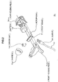
- FIG. 1 is an appearance view of the noise cancelling (NC) earphone device according to one embodiment of the invention.
- the NC earphone device is referred an earphone device with a noise cancelling function. Because the NC earphone device performs to process the noise cancelling by itself, the user may enjoy a noise cancelling effect even when the NC earphone device is connected to a normal audio player.
- the NC earphone device 1 is so-called an ear-hole insertion type of earphone device.
- the ear-hole insertion type of earphone device includes any earphone device of which sound output units are inserted into user's ear-holes so that the users may hear.
- the ear-hole insertion type of earphone device is an in-ear type of earphone device or a canal type of earphone device.
- the NC earphone device 1 shown in FIG. 1 is the canal type of NC earphone device.
- the NC earphone device 1 includes a plug unit 2, a left channel (Lch) output unit 3L, a right channel (Rch) output unit 3R, and a cord housing unit 4.
- the NC earphone device 1 includes an input cord Ci connecting the plug unit 2 to the cord housing unit 4, a left channel cord Cl connecting the Lch output unit 3L to the cord housing unit 4, and a right channel cord Cr connecting the Rch output unit 3R to the cord housing unit 4, as illustrated in FIG. 1 .
- the plug unit 2 is provided to enter sound signals output from an audio player which is connected to the NC earphone 1.
- the plug unit 2 includes three terminals of a left channel (Lch), a right channel (Rch), and a ground (GND), and the input cord Ci includes three wires corresponding to each terminal of the Lch, the Rch, and the GND.
- the Lch output unit 3L outputs sounds based on a left channel sound signal input from the plug unit 2, and the Rch output unit 3R outputs sounds based on a right channel sound signal input from the plug unit 2.
- the Lch output unit 3L includes a housing 3Lh as a case and an earpiece 3Lp detachably mounted to the housing 3Lh.
- the Rch output unit 3R includes a housing 3Rh as a case and an earpiece 3Rp detachably mounted to the housing 3Rh.
- the earpiece 3Lp of the Lch output unit 3L and the earpiece 3Rp of the Rch output unit 3R are inserted to a corresponding ear-hole, respectively, such that output sounds may be heard.
- the Lch output unit 3L and the Rch output unit 3R therefore, include microphones 111 and 11r recording the external sound, respectively.
- the cord housing unit 4 includes an operation unit enabling an on/off operation of the noise cancelling function, in other words a power on/off operation of the NC earphone device 1.
- a control button 4A is installed in the cord housing unit 4, as illustrated in FIG. 1 , and users may perform the on/off operation of the NC earphone device 1 by the control button 4A.
- the on/off operation may be achieved by pressing the control button 4A. Pressing the control button 4A in the off-state performs the on operation, and pressing the control button 4A in the on-state performs the off operation.
- wires are branched to the left channel and the right channel in the cord housing unit 4.
- the Lch, Rch, and GND wires of the input cord Ci are divided to a pair of Lch and GND and a pair of Rch and GND inside of the cord housing unit 4, and the pair of Lch and GND reaches the Lch output unit 3L through the Lch cord Cl and the pair of Rch and GND reaches the Rch output unit 3R through the Rch cord Cr.
- the detailed wiring contained in the Lch cord Cl and the Rch cord Cr will be described later.
- FIGS. 2 and 3 describe a housing of the Lch output unit 3L and the Rch output unit 3R according to the embodiment.
- FIG. 2 shows an exploded perspective view of the Lch output unit 3L.
- descriptions about the housing of the Rch output unit 3R is omitted because the Rch output unit 3R is a left and right reverse form of the Lch output unit 3L with an exception that an LED15 is provided to the Rch output unit 3R as illustrated in FIG. 4 .
- both the Lch output unit 3L and the Lch cord Cl are shown.
- the LED 15 as illustrated in FIG. 4 installed in the Rch output unit 3R is an indicator which represents a remaining amount of the battery and an on/off state of the NC earphone device 1.
- the Lch output unit 3L includes a front housing piece 3Lh-f and a rear housing piece 3Rh-r which make up the housing 3Lh shown in FIG. 1 , the earpiece 3Lp shown in FIG. 1 , and a sleeve 20 guiding the Lch cord Cl in the housing 3Lh.
- a microphone 11l, a driver unit 12l, a circuit board 21, and a battery 13l are accommodated inside of the housing 3Lh having the front housing piece 3Lh-f and the rear housing piece 3Rh-r.
- the microphone 111 is provided to record an external sound. Because a canal type of earphone device employs a feed forward (FF) method to cancel noises, a recording surface of the microphone 11l is looking to an opposite direction to an output direction of the driver unit 121, in order to record the external sound outside of the housing 3Lh.
- the microphone 111 is a Micro Electro Mechanical Systems (MEMS) microphone.
- MEMS Micro Electro Mechanical Systems
- the circuit board 21 includes an electric circuit to achieve the noise cancelling function and other various functions described below.
- a left channel micro-computer 10l or a right channel micro-computer 10r of the Rch output unit 3R is formed on the circuit board 21.
- the battery 13l is provided as part of operating a power source of the electrical circuit formed on the circuit board 21.
- a button-shaped secondary battery may be used.
- the driver unit 12l outputs or plays sounds based on sound signals.
- the driver unit 12l may be a type of Balanced Armature (BA).
- BA Balanced Armature
- a hole of the earpiece 3Lp fits a top tube, having an entrance of the sound emission, of the front housing piece 3Lh-f such that the earpiece 3LP is attached to the housing 3Lh.
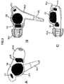
- FIG. 3 represents a positional relationship between the microphone 11l, the driver unit 12l, and the battery 13l which are accommodated in the housing 3Lh.
- FIGS. 3A, 3B, and 3C are perspective drawings of the Lch output unit 3L, and a perspective view, a front view, and a top view, respectively.
- the housing 3Lh is designed to have an approximately cylindrical space separated from a space in which the driver unit 121 is accommodated.
- the approximately cylindrical space is designed to accommodate the circuit board 21 and the button-shaped battery 13l.
- the battery 13l and other components are effectively accommodated in the housing 3Lh of the ear-hole insertion type of earphone device requesting that a housing of the sound output unit has a small size.
- the microphone 11l may be a MEMS microphone. Because the MEMS microphone is small, the microphone as well as the battery 13l and other components are easily accommodated in the housing 3Lh, thereby improving the efficiency of the design, or increasing the degree of freedom in design.
- the driver unit 12l is a BA type of the driver unit, and the BA type of the driver unit has a smaller size, compared to other types of the driver unit such as a dynamic type, such that the housing 3Lh accommodating the battery 13l and other components may be easily designed, thereby increasing the degree of freedom in design.
- the NC earphone device 1 since batteries 13 are accommodated to the housings 3Lh and 3Rh of the Lch output unit and the Rch output unit, the NC earphone device 1 is not used to have the battery box 103A of the cord housing unit 103 in the NC earphone device 100 in related art. Accordingly, the cord housing unit 4 in the present NC earphone device 1 may be significantly small and light so that the weight of the cord housing unit 4 may reduce the deterioration of the feeling of wearing of the Lch and Rch sound output units and the like.
- the NC earphone device 1 includes the Lch sound output unit and the Rch sound output unit which are symmetrical bilaterally except the LED 15.
- the earphone device that the left and right weights of the earphone device are balanced well and the feeling of wearing is excellent may be made.
- Lch and Rch output units are symmetrical bilaterally, empty spaces in the housings of the Lch and the Rch are the same as each other, so that acoustic characteristics of the Lch and the Rch are the same as each other, thereby achieving the natural feeling of hearing.
- the difference between acoustic properties based on whether the weight of the LED 15 is added or not is negligent.
- any one of the Lch and Rch sound output units is designed reversely when the other of the Lch and Rch sound output units is designed, thereby designing easily.
- the sizes of the Lch and Rch sound output units may be equal to each other.
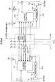
- FIG. 4 is a block diagram illustrating internal components of the NC earphone device according to one embodiment of the invention. Terminals Lch, Rch, and GND formed in the plug unit 2 are omitted in FIG. 4 .
- a left channel (Lch) signal and a right channel (Rch) signal input via the plug unit 2 is input inside of the housings 3Lh and 3Rh through the cord housing unit 4.
- the Lch signal is supplied to the left channel microcomputer 10l and a charging unit 14l.
- two kinds of signals which are a signal through a capacitor Ccl and a signal not through the capacitor Ccl are input the Lch micro-computer 10l as the Lch signal.
- the Rch signal is supplied to the right channel microcomputer 10r and a charging unit 14r.
- two kinds of signals which are a signal through a capacitor Ccr and a signal not through the capacitor Ccr are input the Rch micro-computer 10r as the Rch signal.
- the capacitor Ccl and Ccr are provided for the cut of the DC component.
- the Lch signal through the capacitor Ccl and the Rch signal through the capacitor Ccr may be used to process the noise cancelling by the microcomputers 10l and 10r, respectively, or to process to drive the driver units 12l and 12r, respectively, when the noise cancelling function is turned off.
- signals not through the capacitors Ccl and Ccr which are signals without cutting the DC component, are input to the micro-computers 101 and 10r, respectively, because it is assumed that batteries 131 and 13r are charged through Lch and Rch wirings.
- a direct current is supplied through the Lch and Rch wirings, and the micro-computers 10l and 10r monitor the signals not through the capacitors Ccl and Ccr and determine whether the direct current is supplied or not.
- the micro-computers 10l and 10r instruct the charging units 14l and 14r to charge the batteries 13l and 13r, respectively.
- the charging control unit Fn4 will be described later.
- the charging unit 141 supplies the direct current through the Lch wiring connected to the charging unit 14l to the battery 13l and charges the battery 131.
- the charging unit 14r supplies the direct current through the Rch wiring connected to the charging unit 14r to the battery 13r and charges the battery 13r.
- the micro-computers 10l and 10r executes processes by various units Fn, as illustrated in FIG. 7 , which will be described later.
- the noise cancelling function is performed by the noise cancelling processing unit Fn1 which will be described later.
- the Lch micro-computer 10l generates a noise cancelling signal to cancel external sounds or noises based on the Lch signal input from the capacitor Ccl and a recording signal from the microphone 111, and drives the driver unit 121 based on the noise cancelling signal. Accordingly, a user wearing the NC earphone device 1 may listen to an Lch sound that the external sounds are cancelled. In other words, a noise cancelling effect is obtained.
- a noise cancelling processing by the Rch micro-computer 10r is described in the same way as the Lch micro-computer 10l except the sign of L or R, so that detailed descriptions are omitted.
- the LED 15 is disposed in the housing 3Rh, so that the Rch micro-computer 10r controls to drive the emission of the LED 15.
- the indicator display control unit Fn6 will be described later.
- the Lch micro-computer 10l and the Rch micro-computer 10r are configured to communicate data with each other.
- the Lch micro-computer 101 and the Rch micro-computer 10r are configured to communicate data with each other by a wired connection.
- a serial communication method by Inter-Integrated Circuit (I2C) is employed, and the Lch micro-computer 101 and the Rch micro-computer 10r are connected to each other by wirings of data DATA, a clock CLK, and a ground GND.
- the wirings of data DATA, the clock CLK, and the ground GND connect the Lch micro-computer 10l to the Rch micro-computer 10r through the cord housing unit 4.
- the Lch cord Cl and the Rch cord Cr described above include the wirings of data DATA, the clock CLK, and the ground GND.
- the wiring of the ground is shared with a ground wiring of sound signals.
- the cord housing unit 4 includes the control button 4A and a switch SW.
- the switch SW is configured to inform the micro-computers 101 and 10r of whether the control button 4A is pressed or not.
- an on/off control line ON/OFF extended from the switch SW is connected to the micro-computers 10l and 10r, and the switch SW is configured to disconnect the on/off control line to the wiring of the ground GND based on whether the control button 4A is pressed or not.
- the on/off control line is connected to the Lch micro-computer 10l and the Rch micro-computer 10r through the Lch cord Cl and the Rch cord Cr, respectively.
- NC earphone devices are usually configured to adjust setting values for the noise cancelling processing based on an acoustic inspection, in order to absorb differences between NC earphone devices due to a predetermined timing such as a shipment timing of manufacturing.
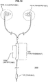
- the NC earphone device 1 includes a communication terminal to allow setting values to be input from the outside of the NC earphone device 1 in the cord housing unit 4.
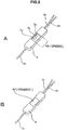
- FIG. 5 is a drawing illustrating a specific embodiment of the communication terminal.
- communication terminals T is exposed on an opposite surface to a surface of the cord housing unit 4 in which the control button 4A is formed.
- an opening 4B is formed in the opposite surface of the cord housing unit 4, and the communication terminals T is exposed within the opening 4B.
- a data terminal Td, a clock terminal Tc, and a ground terminal Tg as the communication terminals T are formed according to the I2C method as the data communication system of the micro-computers 10l and 10r described above.
- the data terminal Td, the clock terminal Tc, and the ground terminal Tg are connected to the data line DATA, the clock line CLK, and the ground line GND, respectively.
- the opening 4B is covered with an ornament 4C before the NC earphone device 1 is shipped.
- the communication terminals T are not exposed to the outside when end users purchase the NC earphone device 1.
- the micro-computers 10l and 10r for the noise cancelling processing are accommodated in the housings of the output unit 3L and 3R, respectively, and the communication terminals T to communicate data between the micro-computers 10l and 10r are disposed in the cord housing unit 4.
- the acoustic inspection is processed under the same condition as actual using when the communication terminals T are exposed in the acoustic inspection, because any part of the output units 3L and 3R is not dissembled.
- the setting value for the noise cancelling processing may be adjusted appropriately.
- the settings for the micro-computers 10l and 10r using the communication terminals T may be adjusted by users as well as at a factory.
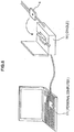
- a cradle 30 which is exclusively or generally accessible to predetermined information processing devices such as a personal computer 31 may be used.
- the cradle 30 includes a fitting portion to fit the cord housing unit 4, and terminals to be connected to the data terminal Td, the clock terminal Tc, and the ground terminal Tg, respectively, are formed in the fitting portion when the cord housing unit 4 is fitted.
- Users may operate the personal computer 31 connected to the cradle 30, so that users adjust various settings of the NC earphone device 1, for example the micro-computers 10l and 10r, where the cord housing unit 4 is fitted to the cradle 30.
- a firmware updates for the micro-computers 10l and 10r or a setting of the frequency characteristic of the equalizer may be also adjusted.
- FIG. 7 shows a block diagram for each function, the each function achieved by software processing of the Lch micro-computer 10l and the Rch micro-computer 10r.
- hardware such as function units Fn configured to process the various functions is described below.
- the Lch micro-computer 10l includes a noise cancelling processing unit Fn1, an NC mode determination processing unit Fn2, a battery level detection unit Fn3, a charging control unit Fn4, and an external input setting processing unit Fn5.
- a noise cancelling processing unit Fn1 an NC mode determination processing unit Fn2
- a battery level detection unit Fn3 a charging control unit Fn4
- an NC mode synchronization control unit Fn7 and an after-level-check simultaneous ON control unit Fn10 are described later.
- the noise cancelling processing unit Fn1 is described as illustrated in FIG. 4 .
- the noise cancelling processing unit Fn1 generates the noise cancelling signal based on the recording signal from the microphone 111 and the Lch signal input from the plug unit 2, and drives the driver unit 12l based on the noise cancelling signal.
- NC mode determination processing unit Fn2 determines an appropriate NC mode depending on a condition of external noises.
- NC modes as NC filter characteristics may be predetermined as A mode (airplane), B mode (bus or train), or C mode (office) such that the NC mode determination processing unit Fn2 determines an appropriate mode among the NC modes according the condition of external noises based on the recording signal from the microphone 11l.
- the battery level detection unit Fn 3 detects a remaining amount of the battery 131.
- the charging control unit Fn4 controls a charging operation of the charging unit 4 for the battery 13l based on a determination result of whether the direct current for charging by the Lch wiring is supplied or not.
- the external input setting processing unit Fn5 receives an input of settings from the external device connected to the communication terminals T and processes settings corresponding to the input. For example, when a filter coefficient of the NC filter is input as a setting value from the external device connected to the communication terminals T, a processing of setting the filter coefficient is executed
- the Rch micro-computer 10r includes four function units Fn among the noise cancelling processing unit Fn1 to the external input setting processing unit Fn5 of the Lch micro-computer 10l excluding the NC mode determination processing unit Fn2.
- the same reference numerals of the each function unit Fn with respect to the Lch micro-computer 10l and the Rch micro-computer 10r are represented, the function units Fn of the Rch micro-computer 10r are described in the same way as the Lch micro-computer 10l except the sign of L or R, so that detailed descriptions are omitted.
- the Rch micro-computer 10r includes an indicator display control unit Fn6 regarding the LED 15 in the housing 3Rh, as well as the four function units Fn1, Fn2, Fn3, and Fn4.
- the indicator display control function unit Fn6 verifies that the Rch micro-computer 10r has a control function of driving the emission of the LED 15.
- the NC mode synchronization control unit Fn7, the error detection control unit Fn8, the simultaneous LR OFF control unit Fn9, and the after-level-check simultaneous ON control unit Fn10 in the Lch micro-computer 10l are described below.
- the Lch micro-computer 10l of the Lch and Rch micro-computers 10l and 10r acts as a master computer.
- the NC mode synchronization control unit Fn7 executes a process for synchronizing on the NC mode of the Lch and Rch output units 3L and 3R.
- the same NC mode determined by the NC mode determination processing unit Fn2 are set in both the Lch and Rch output units 3L and 3R.
- the NC mode synchronization control unit Fn7 controls that switching timings of the NC modes are synchronized with the output units 3L and 3R in order to switch the NC modes simultaneously.
- the error detection control unit Fn8 detects errors of the Rch micro-computer 10r and performs a process corresponding to the errors. For example, in the embodiment, when a state that an operation of the Rch micro-computer 10r has stopped due to any errors, in order words an OFF state of the NC processing, is detected, the Lch micro-computer 101 is shut down or is turned off. In the embodiment, the determination of whether the Rch micro-computer 10r has been stopped or not is performed sequentially when communicating regularly with the Rch micro-computer 10l.
- the simultaneous LR OFF control unit Fn9 is configured to turn off both channels simultaneously when a remaining battery level of any one channel of the both channels is insufficient or less than a predetermined level, even if there is a sufficient remaining amount of the other channel. Accordingly, this configuration may avoid discomfort of users better than a configuration that the left and right of the NC earphone device 1 operate incoherently.
- the after-level-check simultaneous ON control unit Fn10 checks remaining battery levels of the batteries of the left and right channels in response to a power-on instruction from users by the control button 4A, and controls to operate the left and right channels simultaneously only when remaining battery levels of the both channels are sufficient or more than a predetermined level.
- any one channel when an operation is attempted in case that a remaining battery level of any one channel is insufficient, any one channel may be operated but the other channel may be not operated. Accordingly, discomfort of users may occur due to differences in hearing between the left and right channels. However, the discomfort of users may be avoided effectively when operations of both channels are attempted in case that the remaining battery levels of both channels are sufficient.
- the Rch micro-computer 10r includes the remaining level display control unit Fn11. In the embodiment, regarding the processing of the remaining level display control unit Fn11, the Rch micro-computer 10r acts as a master computer.
- the remaining level display control unit Fn11 is configured to display a remaining battery level of any one channel having a smaller remaining battery level than the other channel by the LED 15.
- only one light emitting part of the LED15 may be provided, so that the LED 15 may display the smaller remaining battery level as well as the ON/OFF state.
- these displays by the LED 15 may be configured based on a sequential timing. For example, the LED 15 may acts as an indicator for the display of the remaining battery level when the power is turned on, and then may acts as an indicator for the display of the ON/OFF state.
- the remaining level display control unit Fn11 is performed by the Rch micro-computer 10r, and checks the remaining battery levels of the right and left channels so that a light emission state of the LED 15 is controlled to display the smaller remaining battery level.
- an example of the display technique of the remaining battery level may be the emission brightness, a blink rate, or the like. After the remaining battery level is displayed, it is controlled that the light emission state of the LED 15 displays the ON state
- the both channels are compulsively turned off by the simultaneous LR OFF control unit Fn9 when a remaining battery level of any one channel is insufficient even if a remaining battery level of the other channel is sufficient.
- an appropriate remaining battery level is informed users of the remaining level display control unit Fn11.
- the LED 15 is used to display the remaining battery level when the power is turned on, so that the display of the ON/OFF state and the display of the remaining battery level are performed by one light emission part, or share the one light emission part.
- FIG. 8 is a flowchart illustrating a processing operation corresponding to the NC mode synchronization control unit.
- step S101 of "Lch” it is checked whether the NC mode is changed or not. In other words, it is waited until a new NC mode is determined by the NC mode determination processing unit Fn2.
- step S101 When the NC mode is changed in step S101, the Rch is notified of the NC mode in step S102. In other words, the Rch is notified of the newly determined NC mode.
- the Rch replies to the Lch in Step S201.
- the reply is for the confirmation of the notification.
- step S103 when there is a reply from the Rch, an instruction on switching a mode is executed to the Rch in step S104. Then, the NC mode is switched in step S105.
- the NC mode is a newly determined NC mode, for example a filter characteristic of the NC filter.
- step S202 the Rch is executed to switch to the notified NC mode based on the instruction on switching a mode in step S104. In other words, switching to the NC mode notified from step S104 is executed.
- the Lch waits for a reply from the Rch in response to the notification of the NC mode, and the Lch switches the NC mode of its own, so that the timing of switching the NC mode is synchronized.
- the synchronization of the NC modes in the left and right channels is performed in the timing of switching the NC mode, but also the Lch as a master notifies the Rch of the current NC mode on a regular basis so that the synchronization of the NC modes is performed.
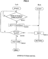
- FIG. 9 is a flowchart illustrating a processing operation corresponding to the error detection control unit. As illustrated in FIG. 9 , the Lch waits until there is a timing of the periodic communication in step S301. In other words, the Lch waits until the timing of the periodic communication with the Rch.
- a periodic notification is executed to the Rch in step S302.
- the Rch replies to the Lch in step S401.
- step S303 when there is the reply, the process returns to step S301. In other words, the process returns to step S301 when there is a reply thereby executing the loop process waiting until an operation stop state or an error state of the Rch is detected.
- step S303 a negative result is obtained when there is no reply from the Rch, shutting down is performed in step S304.
- the Lch may be configured to be an off-state when the Rch is the operation stop state.
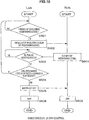
- FIG 10 is a flowchart illustrating a processing operation corresponding to the simultaneous LR OFF control unit Fn9.
- the Lch waits until there is a timing of checking a remaining level in step S501.
- the timing of checking a remaining level refers a predetermined timing of checking a remaining battery level.
- the timing may be a predetermined period of time.
- a request to notify the Rch of a remaining level is performed in step S502.
- the Rch is configured to notify the Lch of the remaining level of the battery 13r in step S601.
- the Lch is waiting for the notification of the remaining level according to step S601. Then, when there is the notification of the remaining level, it is determined whether remaining levels of the both batteries are sufficient or not in step S504. In other words, it is determined whether the remaining level of the battery 13l detected by the battery level detection unit Fn3 and the remaining level of the battery 13r notified from the Rch both are sufficient or more than a predetermined level or not.
- step S504 When the remaining levels of the both batteries 13l and 13r are sufficient to obtain a positive result in step S504, the process returns to step S501.
- the process returns to step S501 when the positive result is obtained in step S504, thereby executing the loop process waiting until a negative result is obtained in step S504 or the remaining levels of the both batteries 13l and 13r are insufficient.
- step S505 is processed to instruct on OFF or shutting down to the Rch. Then, the off state is performed in step S506.
- the Rch is the off state in step S602.
- both the Lch and the Rch is moved to the off-state at the same time.
- FIG. 11 is a flowchart illustrating a processing operation corresponding to the after-level-check simultaneous OFF control unit
- FIG. 12 is a flowchart illustrating a processing operation corresponding to the remaining level display control unit.
- the processing according to the remaining level display control unit Fn11 is performed in response to turning on of the power.
- the processing according to FIG. 12 is a consecutive process of the processing of FIG. 11 .
- the Lch waits until there is an ON operation in step S701. In other words, the Lch waits until a press of the control button 4A is detected.
- a remaining level of the battery 13l is detected as a remaining level detection processing of step S702, and then, the Lch is configured to request the notification of the remaining level to the Rch in step S703.
- the Rch performs to detect a remaining level of the battery 13r as the remaining level detection processing of step S801 according to the request for the remaining level notification of step S703, and after that, the Rch notifies the remaining level detected in step S802.
- the Lch starts to count time in step S704 after requesting the notification of the remaining level in step S703.
- the time count is performed to count the elapsed time since making the request in step S703.
- step S704 After starting the time count in step S704, the Lch waits until a condition of receiving the remaining level notification in step S705 or timing out in step S706 is satisfied. In other words, whether there is the remaining level notification or not is determined in step S705, and then, when a negative result is obtained due to no remaining level notification of the Rch, step S706 is going to determine whether time is out or not, or whether a time count value in step S704 reaches a predetermined value or not. Then, when a negative result is obtained due to no time-out in Step S706, the Lch goes back to step S705.
- step S706 when a positive result with a time-out is obtained in step S706, it may be supposed that the Rch is on any error state, for example, a state that the Rch is incapable of replying due to the depletion of the remaining level of battery 13r.
- step S707 goes to reset the time count, and then, the processing is finished. Accordingly, the Lch may not be solely operated when the Rch is supposed to be incapable of operating, so that operating states of the left and light are balanced.
- step S708 goes to determine whether remaining levels of both channels are sufficient.
- step S709 goes to notify the Rch of the end notification, and then, the processing is finished.
- the Rch finishes the processing according to the end notification from the Lch in step S709, as shown in FIGS. 11 and 12 .
- step S701 goes to perform the ON instruction or a start instruction, and then, the processing of switching to the ON state or starting is executed.
- the Rch executes the processing of switching to the ON state in step S803 based on the ON instruction of step S710.
- both channels are operated simultaneously only when remaining levels of both channels are sufficient.
- the Rch starts by step S803, and then, the Rch requests the notification of the remaining level to the Lch in step S804.
- the Lch is configured to notify the Rch of the remaining level according to the request for the notification of the remaining level from the Rch in step S712.
- step S805 the Rch waits for the notification of the remaining level from the Lch according to step S712.
- step S712 the remaining levels of both channels are compared to each other in step S806, and then, the processing of displaying the smaller remaining level of both channels is executed in step S807.
- a light emitting operation of the LED 15 is controlled to obtain a light emission state representing the smaller remaining level of the batteries 13l and 13r.
- the Lch may receives the remaining level from the Rch so that the Lch may select the smaller remaining level of both channel to transfer the result of the selection to the Rch, thereby controlling to display the remaining level.
- the batteries 13l and 13r to achieve the noise cancelling function are accommodated in the housings of the Lch and the Rch, so that a battery case 103A disposed in the cord housing unit 103 of the NC earphone device 100 is not used. Accordingly, the cord housing unit 4 is made significantly small and light, so that it may be prevented that the feeling of wearing of the Lch and Rch output units 3L and 3R is impaired by the weight of the cord housing unit 4.
- the NC earphone device of the embodiment since the Lch and Rch output units 3L and 3R are symmetrical bilaterally, the NC earphone device that weights of the left and right are balanced well and the feeling of wearing is excellent may be achieved.
- Lch and Rch output units 3L and 3R are symmetrical bilaterally, empty spaces in the housings of the Lch and the Rch are the same as each other, so that acoustic characteristics of the Lch and the Rch are the same as each other, thereby achieving the natural feeling of hearing.
- both the batteries 13l and 13r may be disposed in only one housing of both output units, but by this configuration, the housings of the Lch and the Rch are designed separately.
- the Lch and Rch output units 3L and 3R are symmetrical bilaterally, the ease of design may significantly increase because one output unit may be designed by reversing the design of the other output unit regarding the design of the Lch and Rch output units 3L and 3R.
- the circuit boards 21 or the micro-computers 10 are accommodated in the Lch and Rch output units 3L and 3R, respectively. Accordingly, the circuit boards 21 executing the noise cancelling processing are accommodated in the same housing as the microphones 11, so that a wiring distance between the microphones 11 and the circuit boards 21 may be significantly shorter than the configuration that a circuit board is disposed in the cord housing unit 103 as the earphone device in related art. As a result, the noise generated in the sound recording signal of the microphones 11 may be reduced. In addition, radiation arising from the wiring between the circuit boards 21 and the microphones 11 may be reduced.
- the power supply wiring to the cord housing unit from the battery accommodated in the output unit for the power supply to the circuit board is extended, and as such extent, the number of the wiring increases and a diameter of the cord also increases.
- the described above may be avoided effectively by accommodating the circuit boards 21 in the output units 3L and 3R according to the NC earphone device 1.
- the micro-computers 10 for the noise cancelling processing are accommodated in the housings of the output units 3L and 3R, respectively, and terminals T for the data communication between the micro-computers 10 are disposed in the cord housing unit 4.
- the acoustic inspection is processed under the same condition as actual using when the communication terminals T are exposed in the acoustic inspection, because any part of the output units 3L and 3R is not dissembled.
- the setting value for the noise cancelling processing may be adjusted appropriately.
- the Lch micro-computer 10l and the Rch micro-computer 10r are configured to communicate data from each other, so that one channel may check an operation status of the other channel. Accordingly, it may be avoided effectively that the discomfort for the incongruity of the left and right channel operation occurs because the Lch and the Rch fail to check the operation status of each other, and therefore, operations of both channels are balanced. As a result, it may be avoided effectively that users feel the discomfort for the incongruity of the left and right channel operation.
Description
- The present invention relates to a to an ear-hole insertion type earphone device having a noise cancelling function.
- Earphone devices with a noise cancelling function (hereinafter, also referred to as NC earphone devices) have come into wide use. Because an NC earphone device performs noise cancelling processing by itself, users may enjoy a noise cancelling effect even when the NC earphone device is connected to a normal audio player.
-
FIG. 13 is a diagram showing an appearance of a knownNC earphone device 100. The NCearphone device 100 shown inFIG. 13 is a so-called ear-hole insertion type of earphone device. Here, the ear-hole insertion type of earphone device includes any earphone device of which sound output units are inserted into user's ear-holes so that the users may hear. For example, the ear-hole insertion type of earphone device is an in-ear type of earphone device or a canal type of earphone device. The NCearphone device 100 shown inFIG. 13 is the canal type of NC earphone device. - As illustrated in
FIG. 13 , the NCdevice earphone 100 has a left channel (Lch)output unit 101 L, a right channel (Rch)output unit 101 R, aplug unit 102, and acord housing unit 103. A cord connects theplug unit 102 to thecord housing unit 103, and each cord connects theLch output unit 101 L and theRch output unit 101 R to thecord housing unit 103, as illustrated inFIG. 13 . - A driver unit outputting sounds corresponding to sound signals input from the
plug unit 102 and a microphone recording external sounds for the realization of the noise cancelling function are installed in theLch output unit 101 L and theRch output unit 101 R, respectively. - An electric circuit unit (a noise cancelling processing unit) to provide the noise cancelling function is installed inside of the
cord housing unit 103. The noise cancelling processing unit generates a noise cancelling signal of the left channel based on a Lch sound signal input from theplug unit 102 and a sound signal recorded from the microphone of theLch output unit 101 L and a noise cancelling signal of the right channel based on a Rch sound signal input from theplug unit 102 and a sound signal recorded from the microphone of theRch output unit 101 R. When the noise cancelling processing unit drives the driver unit of theLch output unit 101L according to the noise cancelling signal of the left channel and the driver unit of theRch output unit 101R according to the noise cancelling signal of the right channel, users wearing the NCearphone device 100 may hear noise-cancelled sounds. - Here, the NC earphone device requests to supply the power of its own that is used for the noise cancelling processing, in order to be suitable for an usual audio player, for example, having output terminals of Lch, Rch, and GND. In a known NC
earphone device 100, thebattery case 103A accommodating a battery for the power supply is formed in thecord housing unit 103, as illustrated inFigure 13 . - However, when the
battery case 103A is formed in thecord housing unit 103, as such an extent, thecord housing unit 103 becomes enlarged. For example, the size of thebattery case 103A is considerably large because NCearphone device 100 is considered to use a single AA-sized first battery or a single AAA-sized first battery. - In addition, when the
battery case 103A is provided, the weight of thecord housing unit 103 increases due to the accommodating of the battery, and accordingly, the feeling of wearing may be impaired because theLch output unit 101L and theRch output unit 101R are pulled down. In addition, in order to solve the problem in the past, providing a clip fixing thecord housing unit 103 in appropriate positions such as an edge of the breast pocket, the tension from thecord housing unit 103 due to the weight of the Lch andRch output units -
WO 2011/031910 discloses electroacoustical speaker devices that synchronously play audio received from a source. In one embodiment, one speaker acts as the master and the other speaker acts as the slave. The master speaker receives digital audio data from a source and, in addition to playing the digital audio received from the source, the master speaker retransmits the digital audio to the slave speaker. The master speaker additionally sends synchronization data to the slave speaker, such as data that indicates the buffer status or playback position of the master speaker. The slave speaker utilizes the synchronization data from the master speaker to adjust, for example, its buffer status or playback position, so that the two speakers play the audio synchronously (e.g., within thirty milliseconds). In one embodiment, the master speaker uses a connection-oriented protocol, such as TCP/IP, to transmit buffered audio data to the slave speaker and uses a connectionless protocol, such as UDP or ICMP, for the synchronization data. In addition, the speakers may transition roles as master and slave. Each earphone contains a battery, a DSP and, optionally, a microphone. The DSP may be used to perform noise cancellation. -
WO 2007/140403 discloses a receiver module for a personal listening device to be fitted in the ear, on the ear, near the ear, or behind the ear, the receiver module having a movable armature, the receiver module comprising a motor assembly and a housing defining a chamber, the housing being made from a material that is corrosion resistant and is biocompatible to human skin contact. The receiver module further comprises at least one motor assembly directly disposed in the chamber, and optionally a communication link adapted to couple or decouple with the motor assembly. At least a portion of the communication link is disposed in the housing. -
- Various respective aspects and features of the invention are defined in the appended claims. Combinations of features from the dependent claims may be combined with features of the independent claims as appropriate and not merely as explicitly set out in the claims.
- In order to help address the problems described above, ear hole insertion type earphone device described herein has a noise cancelling function. The ear hole insertion type earphone device described herein has a left channel housing unit accommodating a left channel driver unit outputting a left channel sound and a right channel housing unit accommodating a right channel driver unit outputting a right channel sound, and a microphone for the noise cancelling and a battery are accommodated in each of the left and right channel housing units.
- According to an embodiment of the invention, the batteries to achieve the noise cancelling function are accommodated in the housings of the Lch and the Rch, so that the battery case disposed in the cord housing unit of the NC earphone device in related art may not be used in the embodiment. Accordingly, the cord housing unit is made significantly small and light, so that it may be prevented that the feeling of wearing of the Lch and Rch output units or sound output units is impaired by the weight of the cord housing unit. In addition, an embodiment of the invention, since the Lch and Rch output units are symmetrical bilaterally, the earphone device that weights of the left and right are balanced well and the feeling of wearing is excellent may be achieved. In addition, when the Lch and Rch output units are symmetrical bilaterally, empty spaces in the housings of the Lch and the Rch are the same as each other, so that acoustic characteristics of the Lch and the Rch are the same as each other, thereby achieving the natural feeling of hearing. In addition, as the configuration that the batteries are not accomodated in the cord housing unit, both batteries may be disposed in one housing of both output units, but by this configuration, the housings of the Lch and the Rch are designed separately. However, when the Lch and Rch output units are symmetrical bilaterally, the ease of design may significantly increase because one output unit may be designed by reversing the design of the other output unit regarding the design of the Lch and Rch output units.
JP 2003-47083 - As described herein, a battery case may be omitted from a cord housing unit such that the earphone device with the excellent feeling of wearing may be achieved. As described herein, since the Lch and Rch output units are symmetrical bilaterally, the earphone device that weights of the left and right are balanced well and the feeling of wearing is excellent may be achieved. In addition, when the Lch and Rch output units are symmetrical bilaterally, acoustic characteristics of the Lch and the Rch are the same as each other, thereby achieving the natural feeling of hearing.
- Embodiments of the invention will now be described with reference to the accompanying drawings, throughout which like parts are referred to by like references, and in which:
-
FIG. 1 is an appearance diagram of the NC earphone device according to one embodiment of the invention; -
FIG. 2 is an exploded perspective view of the Lch output unit according to one embodiment of the invention; -
FIG. 3 is a drawing illustrating a position relationship of the microphone, the driver unit, and the battery accommodated in the housing; -
FIG. 4 is a block diagram illustrating internal components of the NC earphone device according to an embodiment of the invention; -
FIG. 5 is a drawing illustrating a specific embodiment of the communication terminal; -
FIG. 6 is a drawing illustrating a specific embodiment of the connection when users make various settings by using the communication terminal; -
FIG. 7 is a drawing illustrating various functions of the left channel micro-computer and the right channel micro-computer; -
FIG. 8 is a flowchart illustrating a processing operation corresponding to NC mode synchronization control function unit; -
FIG. 9 is a flowchart illustrating a processing operation corresponding to the error detection control unit; -
FIG. 10 is a flowchart illustrating a processing operation corresponding to the simultaneous LR OFF control unit; -
FIG. 11 is a flowchart illustrating a processing operation corresponding to the after-level-check simultaneous OFF control unit; -
FIG. 12 is a flowchart illustrating a processing operation corresponding to the remaining level display control unit; and -
FIG. 13 is an appearance diagram of a known NC earphone device. - Hereinafter, preferred embodiments of the present invention will be described in detail with reference to the appended drawings. Note that, in this specification and the appended drawings, structural elements that have substantially the same function and structure are denoted with the same reference numerals, and repeated explanation of these structural elements is omitted.
- Note that the description will be made in the following order:
- 1. Device structure according to one embodiment of the invention;
- 2. Device internal configuration according to one embodiment of the invention;
- 3. Communication with external devices;
- 4. Various functions;
- 5. Processing procedures;
- 6. Summary; and
- 7. Modified Examples.
-
FIG. 1 is an appearance view of the noise cancelling (NC) earphone device according to one embodiment of the invention. Here, the NC earphone device is referred an earphone device with a noise cancelling function. Because the NC earphone device performs to process the noise cancelling by itself, the user may enjoy a noise cancelling effect even when the NC earphone device is connected to a normal audio player. - The
NC earphone device 1 is so-called an ear-hole insertion type of earphone device. Here, the ear-hole insertion type of earphone device includes any earphone device of which sound output units are inserted into user's ear-holes so that the users may hear. For example, the ear-hole insertion type of earphone device is an in-ear type of earphone device or a canal type of earphone device. TheNC earphone device 1 shown inFIG. 1 is the canal type of NC earphone device. - As illustrated in
FIG. 1 , theNC earphone device 1 includes aplug unit 2, a left channel (Lch)output unit 3L, a right channel (Rch)output unit 3R, and acord housing unit 4. In addition, theNC earphone device 1 includes an input cord Ci connecting theplug unit 2 to thecord housing unit 4, a left channel cord Cl connecting theLch output unit 3L to thecord housing unit 4, and a right channel cord Cr connecting theRch output unit 3R to thecord housing unit 4, as illustrated inFIG. 1 . - The
plug unit 2 is provided to enter sound signals output from an audio player which is connected to theNC earphone 1. In the embodiment, theplug unit 2 includes three terminals of a left channel (Lch), a right channel (Rch), and a ground (GND), and the input cord Ci includes three wires corresponding to each terminal of the Lch, the Rch, and the GND. - The
Lch output unit 3L outputs sounds based on a left channel sound signal input from theplug unit 2, and theRch output unit 3R outputs sounds based on a right channel sound signal input from theplug unit 2. TheLch output unit 3L includes a housing 3Lh as a case and an earpiece 3Lp detachably mounted to the housing 3Lh. In similar, theRch output unit 3R includes a housing 3Rh as a case and an earpiece 3Rp detachably mounted to the housing 3Rh. The earpiece 3Lp of theLch output unit 3L and the earpiece 3Rp of theRch output unit 3R are inserted to a corresponding ear-hole, respectively, such that output sounds may be heard. - Here, in order to realize a noise cancelling function, it is provided to record an external sound (external noise). The
Lch output unit 3L and theRch output unit 3R, therefore, includemicrophones - The
cord housing unit 4 includes an operation unit enabling an on/off operation of the noise cancelling function, in other words a power on/off operation of theNC earphone device 1. In particular, acontrol button 4A is installed in thecord housing unit 4, as illustrated inFIG. 1 , and users may perform the on/off operation of theNC earphone device 1 by thecontrol button 4A. For example, the on/off operation may be achieved by pressing thecontrol button 4A. Pressing thecontrol button 4A in the off-state performs the on operation, and pressing thecontrol button 4A in the on-state performs the off operation. - In an embodiment, wires are branched to the left channel and the right channel in the
cord housing unit 4. In particular, the Lch, Rch, and GND wires of the input cord Ci are divided to a pair of Lch and GND and a pair of Rch and GND inside of thecord housing unit 4, and the pair of Lch and GND reaches theLch output unit 3L through the Lch cord Cl and the pair of Rch and GND reaches theRch output unit 3R through the Rch cord Cr. The detailed wiring contained in the Lch cord Cl and the Rch cord Cr will be described later. - Next,
FIGS. 2 and3 describe a housing of theLch output unit 3L and theRch output unit 3R according to the embodiment.FIG. 2 shows an exploded perspective view of theLch output unit 3L. Here, descriptions about the housing of theRch output unit 3R is omitted because theRch output unit 3R is a left and right reverse form of theLch output unit 3L with an exception that an LED15 is provided to theRch output unit 3R as illustrated inFIG. 4 . InFIG. 2 , both theLch output unit 3L and the Lch cord Cl are shown. In addition, theLED 15 as illustrated inFIG. 4 installed in theRch output unit 3R is an indicator which represents a remaining amount of the battery and an on/off state of theNC earphone device 1. - The
Lch output unit 3L includes a front housing piece 3Lh-f and a rear housing piece 3Rh-r which make up the housing 3Lh shown inFIG. 1 , the earpiece 3Lp shown inFIG. 1 , and asleeve 20 guiding the Lch cord Cl in the housing 3Lh. - In addition, in the embodiment, a microphone 11l, a driver unit 12l, a
circuit board 21, and a battery 13l are accommodated inside of the housing 3Lh having the front housing piece 3Lh-f and the rear housing piece 3Rh-r. - The
microphone 111 is provided to record an external sound. Because a canal type of earphone device employs a feed forward (FF) method to cancel noises, a recording surface of the microphone 11l is looking to an opposite direction to an output direction of thedriver unit 121, in order to record the external sound outside of the housing 3Lh. For example, themicrophone 111 is a Micro Electro Mechanical Systems (MEMS) microphone. - The
circuit board 21 includes an electric circuit to achieve the noise cancelling function and other various functions described below. A left channel micro-computer 10l or aright channel micro-computer 10r of theRch output unit 3R is formed on thecircuit board 21. - The battery 13l is provided as part of operating a power source of the electrical circuit formed on the
circuit board 21. In the embodiment, a button-shaped secondary battery may be used. - The driver unit 12l outputs or plays sounds based on sound signals. In the embodiment, the driver unit 12l may be a type of Balanced Armature (BA).
- In the embodiment, a hole of the earpiece 3Lp fits a top tube, having an entrance of the sound emission, of the front housing piece 3Lh-f such that the earpiece 3LP is attached to the housing 3Lh.
-
FIG. 3 represents a positional relationship between the microphone 11l, the driver unit 12l, and the battery 13l which are accommodated in the housing 3Lh.FIGS. 3A, 3B, and 3C are perspective drawings of theLch output unit 3L, and a perspective view, a front view, and a top view, respectively. - As illustrated in
FIG. 2 andFIG. 3 , the housing 3Lh is designed to have an approximately cylindrical space separated from a space in which thedriver unit 121 is accommodated. The approximately cylindrical space is designed to accommodate thecircuit board 21 and the button-shaped battery 13l. According to the design of the housing 3Lh, the battery 13l and other components are effectively accommodated in the housing 3Lh of the ear-hole insertion type of earphone device requesting that a housing of the sound output unit has a small size. - In the embodiment, the microphone 11l may be a MEMS microphone. Because the MEMS microphone is small, the microphone as well as the battery 13l and other components are easily accommodated in the housing 3Lh, thereby improving the efficiency of the design, or increasing the degree of freedom in design.
- In the embodiment, the driver unit 12l is a BA type of the driver unit, and the BA type of the driver unit has a smaller size, compared to other types of the driver unit such as a dynamic type, such that the housing 3Lh accommodating the battery 13l and other components may be easily designed, thereby increasing the degree of freedom in design.
- Here, according to the
NC earphone device 1, since batteries 13 are accommodated to the housings 3Lh and 3Rh of the Lch output unit and the Rch output unit, theNC earphone device 1 is not used to have thebattery box 103A of thecord housing unit 103 in theNC earphone device 100 in related art. Accordingly, thecord housing unit 4 in the presentNC earphone device 1 may be significantly small and light so that the weight of thecord housing unit 4 may reduce the deterioration of the feeling of wearing of the Lch and Rch sound output units and the like. - In addition, the
NC earphone device 1 according to the embodiment includes the Lch sound output unit and the Rch sound output unit which are symmetrical bilaterally except theLED 15. As a result, the earphone device that the left and right weights of the earphone device are balanced well and the feeling of wearing is excellent may be made. - In addition, when the Lch and Rch output units are symmetrical bilaterally, empty spaces in the housings of the Lch and the Rch are the same as each other, so that acoustic characteristics of the Lch and the Rch are the same as each other, thereby achieving the natural feeling of hearing.
- Because the
LED 15 is very compact and light, the difference between acoustic properties based on whether the weight of theLED 15 is added or not is negligent. - In addition, when the battery 13 is accommodated in any one of the Lch and Rch housings as the design that the battery 13 is disposed in another position than the
cord housing unit 4, the Lch and Rch housings are independently designed. In contrast, according to the embodiment with a symmetrical structure, with respect to designs of the Lch and Rch sound output units, any one of the Lch and Rch sound output units is designed reversely when the other of the Lch and Rch sound output units is designed, thereby designing easily. - In addition, when batteries are disposed in both sides of the Lch and Rch sound output units other than a single battery design, the sizes of the Lch and Rch sound output units may be equal to each other.
-
FIG. 4 is a block diagram illustrating internal components of the NC earphone device according to one embodiment of the invention. Terminals Lch, Rch, and GND formed in theplug unit 2 are omitted inFIG. 4 . - First, a left channel (Lch) signal and a right channel (Rch) signal input via the
plug unit 2 is input inside of the housings 3Lh and 3Rh through thecord housing unit 4. In the housing 3Lh, the Lch signal is supplied to the left channel microcomputer 10l and a charging unit 14l. In the embodiment, two kinds of signals which are a signal through a capacitor Ccl and a signal not through the capacitor Ccl are input the Lch micro-computer 10l as the Lch signal. Similarly, in the housing 3Rh, the Rch signal is supplied to theright channel microcomputer 10r and acharging unit 14r. In the embodiment, two kinds of signals which are a signal through a capacitor Ccr and a signal not through the capacitor Ccr are input theRch micro-computer 10r as the Rch signal. The capacitor Ccl and Ccr are provided for the cut of the DC component. The Lch signal through the capacitor Ccl and the Rch signal through the capacitor Ccr may be used to process the noise cancelling by themicrocomputers 10l and 10r, respectively, or to process to drive thedriver units 12l and 12r, respectively, when the noise cancelling function is turned off. - Here, in the embodiment, signals not through the capacitors Ccl and Ccr, which are signals without cutting the DC component, are input to the
micro-computers batteries micro-computers 10l and 10r monitor the signals not through the capacitors Ccl and Ccr and determine whether the direct current is supplied or not. When the direct current is supplied, themicro-computers 10l and 10r instruct the chargingunits 14l and 14r to charge thebatteries 13l and 13r, respectively. In this regard, the charging control unit Fn4 will be described later. In addition, as illustrated inFIG. 4 , the chargingunit 141 supplies the direct current through the Lch wiring connected to the charging unit 14l to the battery 13l and charges thebattery 131. In similar, thecharging unit 14r supplies the direct current through the Rch wiring connected to thecharging unit 14r to thebattery 13r and charges thebattery 13r. - The
micro-computers 10l and 10r executes processes by various units Fn, as illustrated inFIG. 7 , which will be described later. For example, the noise cancelling function is performed by the noise cancelling processing unit Fn1 which will be described later. Specifically, the Lch micro-computer 10l generates a noise cancelling signal to cancel external sounds or noises based on the Lch signal input from the capacitor Ccl and a recording signal from themicrophone 111, and drives thedriver unit 121 based on the noise cancelling signal. Accordingly, a user wearing theNC earphone device 1 may listen to an Lch sound that the external sounds are cancelled. In other words, a noise cancelling effect is obtained. In addition, a noise cancelling processing by theRch micro-computer 10r is described in the same way as the Lch micro-computer 10l except the sign of L or R, so that detailed descriptions are omitted. - In the embodiment, the
LED 15 is disposed in the housing 3Rh, so that theRch micro-computer 10r controls to drive the emission of theLED 15. In this regard, the indicator display control unit Fn6 will be described later. - In an embodiment, the Lch micro-computer 10l and the
Rch micro-computer 10r are configured to communicate data with each other. For example, theLch micro-computer 101 and theRch micro-computer 10r are configured to communicate data with each other by a wired connection. In this case, as the data communication system, a serial communication method by Inter-Integrated Circuit (I2C) is employed, and theLch micro-computer 101 and theRch micro-computer 10r are connected to each other by wirings of data DATA, a clock CLK, and a ground GND. - As illustrated in the
FIG. 4 , the wirings of data DATA, the clock CLK, and the ground GND connect the Lch micro-computer 10l to the Rch micro-computer 10r through thecord housing unit 4. The Lch cord Cl and the Rch cord Cr described above include the wirings of data DATA, the clock CLK, and the ground GND. In addition, in the embodiment, the wiring of the ground is shared with a ground wiring of sound signals. - The
cord housing unit 4 includes thecontrol button 4A and a switch SW. The switch SW is configured to inform themicro-computers control button 4A is pressed or not. In particular, an on/off control line ON/OFF extended from the switch SW is connected to themicro-computers 10l and 10r, and the switch SW is configured to disconnect the on/off control line to the wiring of the ground GND based on whether thecontrol button 4A is pressed or not. In addition, the on/off control line is connected to the Lch micro-computer 10l and the Rch micro-computer 10r through the Lch cord Cl and the Rch cord Cr, respectively. - Here, NC earphone devices are usually configured to adjust setting values for the noise cancelling processing based on an acoustic inspection, in order to absorb differences between NC earphone devices due to a predetermined timing such as a shipment timing of manufacturing.
- In an embodiment, the
NC earphone device 1 includes a communication terminal to allow setting values to be input from the outside of theNC earphone device 1 in thecord housing unit 4. -
FIG. 5 is a drawing illustrating a specific embodiment of the communication terminal. As shown inFIG. 5A , communication terminals T is exposed on an opposite surface to a surface of thecord housing unit 4 in which thecontrol button 4A is formed. In particular, anopening 4B is formed in the opposite surface of thecord housing unit 4, and the communication terminals T is exposed within theopening 4B. In the embodiment, a data terminal Td, a clock terminal Tc, and a ground terminal Tg as the communication terminals T are formed according to the I2C method as the data communication system of themicro-computers 10l and 10r described above. As shown inFIG. 4 , the data terminal Td, the clock terminal Tc, and the ground terminal Tg are connected to the data line DATA, the clock line CLK, and the ground line GND, respectively. - As illustrated in
FIG. 5B , theopening 4B is covered with anornament 4C before theNC earphone device 1 is shipped. In other words, the communication terminals T are not exposed to the outside when end users purchase theNC earphone device 1. - In the embodiment, the
micro-computers 10l and 10r for the noise cancelling processing are accommodated in the housings of theoutput unit micro-computers 10l and 10r are disposed in thecord housing unit 4. As such the configuration, the acoustic inspection is processed under the same condition as actual using when the communication terminals T are exposed in the acoustic inspection, because any part of theoutput units - Here, the settings for the
micro-computers 10l and 10r using the communication terminals T may be adjusted by users as well as at a factory. When users adjust various settings, as illustrated inFIG. 6 , acradle 30 which is exclusively or generally accessible to predetermined information processing devices such as apersonal computer 31 may be used. For example, an illustrated inFIG. 6 , thecradle 30 includes a fitting portion to fit thecord housing unit 4, and terminals to be connected to the data terminal Td, the clock terminal Tc, and the ground terminal Tg, respectively, are formed in the fitting portion when thecord housing unit 4 is fitted. - Users may operate the
personal computer 31 connected to thecradle 30, so that users adjust various settings of theNC earphone device 1, for example themicro-computers 10l and 10r, where thecord housing unit 4 is fitted to thecradle 30. - As an example setting, there may be a customizable filter characteristic setting of the NC filter or an optimal gain setting of the NC filter. A firmware updates for the
micro-computers 10l and 10r or a setting of the frequency characteristic of the equalizer may be also adjusted. - Here, various functions of the
Lch micro-computer 101 and theRch micro-computer 10r in theNC earphone device 1 are described below as shown inFIG. 7 . In addition,FIG. 7 shows a block diagram for each function, the each function achieved by software processing of the Lch micro-computer 10l and the Rch micro-computer 10r. Regarding various functions achieved by software processing, hardware such as function units Fn configured to process the various functions is described below. - As illustrated in
FIG. 7 , the Lch micro-computer 10l includes a noise cancelling processing unit Fn1, an NC mode determination processing unit Fn2, a battery level detection unit Fn3, a charging control unit Fn4, and an external input setting processing unit Fn5. In addition, an NC mode synchronization control unit Fn7 and an after-level-check simultaneous ON control unit Fn10 are described later. - The noise cancelling processing unit Fn1 is described as illustrated in
FIG. 4 . The noise cancelling processing unit Fn1 generates the noise cancelling signal based on the recording signal from themicrophone 111 and the Lch signal input from theplug unit 2, and drives the driver unit 12l based on the noise cancelling signal. - The NC mode determination processing unit Fn2 determines an appropriate NC mode depending on a condition of external noises. For example, in the embodiment, NC modes as NC filter characteristics may be predetermined as A mode (airplane), B mode (bus or train), or C mode (office) such that the NC mode determination processing unit Fn2 determines an appropriate mode among the NC modes according the condition of external noises based on the recording signal from the microphone 11l.
- In addition, the battery level
detection unit Fn 3 detects a remaining amount of thebattery 131. In addition, as described inFIG. 4 , the charging control unit Fn4 controls a charging operation of the chargingunit 4 for the battery 13l based on a determination result of whether the direct current for charging by the Lch wiring is supplied or not. - The external input setting processing unit Fn5 receives an input of settings from the external device connected to the communication terminals T and processes settings corresponding to the input. For example, when a filter coefficient of the NC filter is input as a setting value from the external device connected to the communication terminals T, a processing of setting the filter coefficient is executed
- On the other hand, the Rch micro-computer 10r includes four function units Fn among the noise cancelling processing unit Fn1 to the external input setting processing unit Fn5 of the Lch micro-computer 10l excluding the NC mode determination processing unit Fn2. Here, the same reference numerals of the each function unit Fn with respect to the Lch micro-computer 10l and the
Rch micro-computer 10r are represented, the function units Fn of theRch micro-computer 10r are described in the same way as the Lch micro-computer 10l except the sign of L or R, so that detailed descriptions are omitted. - In addition, the Rch micro-computer 10r includes an indicator display control unit Fn6 regarding the
LED 15 in the housing 3Rh, as well as the four function units Fn1, Fn2, Fn3, and Fn4. The indicator display control function unit Fn6 verifies that theRch micro-computer 10r has a control function of driving the emission of theLED 15. - The NC mode synchronization control unit Fn7, the error detection control unit Fn8, the simultaneous LR OFF control unit Fn9, and the after-level-check simultaneous ON control unit Fn10 in the Lch micro-computer 10l are described below. Here, regarding the processing of the NC mode synchronization control unit Fn7 and the after-level-check simultaneous ON control unit Fn10, the Lch micro-computer 10l of the Lch and
Rch micro-computers 10l and 10r acts as a master computer. - First, the NC mode synchronization control unit Fn7 executes a process for synchronizing on the NC mode of the Lch and
Rch output units Rch output units - Here, when the NC modes of the Lch and
Rch output units output units - The error detection control unit Fn8 detects errors of the
Rch micro-computer 10r and performs a process corresponding to the errors. For example, in the embodiment, when a state that an operation of theRch micro-computer 10r has stopped due to any errors, in order words an OFF state of the NC processing, is detected, theLch micro-computer 101 is shut down or is turned off. In the embodiment, the determination of whether theRch micro-computer 10r has been stopped or not is performed sequentially when communicating regularly with the Rch micro-computer 10l. - By the processing of the error detection control unit Fn8 like this, a situation that operating states become incoherent in the left and right of the
NC earphone device 1 may be avoided effectively. For example, discomfort of users due to differences in hearing between the left and right of theNC earphone device 1 when only the Lch micro-computer is turned on may be avoided effectively. In addition, it is noted that when themicro-computers 10l and 10r is turned off, only the noise cancelling function is turned off but the sound output itself based on sound signals is continued. - In addition, the simultaneous LR OFF control unit Fn9 is configured to turn off both channels simultaneously when a remaining battery level of any one channel of the both channels is insufficient or less than a predetermined level, even if there is a sufficient remaining amount of the other channel. Accordingly, this configuration may avoid discomfort of users better than a configuration that the left and right of the
NC earphone device 1 operate incoherently. - In addition, the after-level-check simultaneous ON control unit Fn10 checks remaining battery levels of the batteries of the left and right channels in response to a power-on instruction from users by the
control button 4A, and controls to operate the left and right channels simultaneously only when remaining battery levels of the both channels are sufficient or more than a predetermined level. - Here, when an operation is attempted in case that a remaining battery level of any one channel is insufficient, any one channel may be operated but the other channel may be not operated. Accordingly, discomfort of users may occur due to differences in hearing between the left and right channels. However, the discomfort of users may be avoided effectively when operations of both channels are attempted in case that the remaining battery levels of both channels are sufficient.
- In addition, the
Rch micro-computer 10r includes the remaining level display control unit Fn11. In the embodiment, regarding the processing of the remaining level display control unit Fn11, theRch micro-computer 10r acts as a master computer. - The remaining level display control unit Fn11 is configured to display a remaining battery level of any one channel having a smaller remaining battery level than the other channel by the
LED 15. Here, in the embodiment, only one light emitting part of the LED15 may be provided, so that theLED 15 may display the smaller remaining battery level as well as the ON/OFF state. In the embodiment, these displays by theLED 15 may be configured based on a sequential timing. For example, theLED 15 may acts as an indicator for the display of the remaining battery level when the power is turned on, and then may acts as an indicator for the display of the ON/OFF state. - In this regard, the remaining level display control unit Fn11 is performed by the Rch micro-computer 10r, and checks the remaining battery levels of the right and left channels so that a light emission state of the
LED 15 is controlled to display the smaller remaining battery level. Here, an example of the display technique of the remaining battery level may be the emission brightness, a blink rate, or the like. After the remaining battery level is displayed, it is controlled that the light emission state of theLED 15 displays the ON state - Here, in the embodiment, the both channels are compulsively turned off by the simultaneous LR OFF control unit Fn9 when a remaining battery level of any one channel is insufficient even if a remaining battery level of the other channel is sufficient. In this regard, an appropriate remaining battery level is informed users of the remaining level display control unit Fn11.
- In addition, in the embodiment, the
LED 15 is used to display the remaining battery level when the power is turned on, so that the display of the ON/OFF state and the display of the remaining battery level are performed by one light emission part, or share the one light emission part. - As illustrated in flowcharts of
FIG. 8 to FIG. 12 , detailed processing procedures that are executed to achieve various functions of the NC mode synchronization control unit Fn7 to the remaining level display control unit Fn11 are described below. With respect toFIGS. 8 to 12 , processes of "Lch" are executed by the Lch micro-computer 10l, and processes of "Rch" are executed by the Rch micro-computer 10r. -
FIG. 8 is a flowchart illustrating a processing operation corresponding to the NC mode synchronization control unit. First, in step S101 of "Lch", it is checked whether the NC mode is changed or not. In other words, it is waited until a new NC mode is determined by the NC mode determination processing unit Fn2. - When the NC mode is changed in step S101, the Rch is notified of the NC mode in step S102. In other words, the Rch is notified of the newly determined NC mode.
- According to the notification of the NC mode, the Rch replies to the Lch in Step S201. For example, the reply is for the confirmation of the notification.
- The Lch is waiting for a reply from the Rch in step S103. In step S103, when there is a reply from the Rch, an instruction on switching a mode is executed to the Rch in step S104. Then, the NC mode is switched in step S105. In other words, the NC mode is a newly determined NC mode, for example a filter characteristic of the NC filter.
- In step S202, the Rch is executed to switch to the notified NC mode based on the instruction on switching a mode in step S104. In other words, switching to the NC mode notified from step S104 is executed.
- As described above, the Lch waits for a reply from the Rch in response to the notification of the NC mode, and the Lch switches the NC mode of its own, so that the timing of switching the NC mode is synchronized.
- Further, the synchronization of the NC modes in the left and right channels is performed in the timing of switching the NC mode, but also the Lch as a master notifies the Rch of the current NC mode on a regular basis so that the synchronization of the NC modes is performed.
-
FIG. 9 is a flowchart illustrating a processing operation corresponding to the error detection control unit. As illustrated inFIG. 9 , the Lch waits until there is a timing of the periodic communication in step S301. In other words, the Lch waits until the timing of the periodic communication with the Rch. - Then, when the timing of the periodic communication comes, a periodic notification is executed to the Rch in step S302. According to the periodic notification, the Rch replies to the Lch in step S401.
- The Lch is determined whether there is the reply according to step S401 or not. In step S303, when there is the reply, the process returns to step S301. In other words, the process returns to step S301 when there is a reply thereby executing the loop process waiting until an operation stop state or an error state of the Rch is detected.
- In step S303, a negative result is obtained when there is no reply from the Rch, shutting down is performed in step S304. Accordingly, the Lch may be configured to be an off-state when the Rch is the operation stop state.
-
FIG 10 is a flowchart illustrating a processing operation corresponding to the simultaneous LR OFF control unit Fn9. As illustrated inFIG. 10 , the Lch waits until there is a timing of checking a remaining level in step S501. Here, the timing of checking a remaining level refers a predetermined timing of checking a remaining battery level. For example, the timing may be a predetermined period of time. - When there is the timing of checking a remaining level, a request to notify the Rch of a remaining level is performed in step S502. According to the request for the notification of the remaining level, the Rch is configured to notify the Lch of the remaining level of the
battery 13r in step S601. - The Lch is waiting for the notification of the remaining level according to step S601. Then, when there is the notification of the remaining level, it is determined whether remaining levels of the both batteries are sufficient or not in step S504. In other words, it is determined whether the remaining level of the battery 13l detected by the battery level detection unit Fn3 and the remaining level of the
battery 13r notified from the Rch both are sufficient or more than a predetermined level or not. - When the remaining levels of the both
batteries 13l and 13r are sufficient to obtain a positive result in step S504, the process returns to step S501. The process returns to step S501 when the positive result is obtained in step S504, thereby executing the loop process waiting until a negative result is obtained in step S504 or the remaining levels of the bothbatteries 13l and 13r are insufficient. - When the remaining levels of the both
batteries - According to the instruction on OFF in step S505, the Rch is the off state in step S602.
- According to a series of processing as described above, when the remaining level of at least one battery is insufficient, both the Lch and the Rch is moved to the off-state at the same time.
-
FIG. 11 is a flowchart illustrating a processing operation corresponding to the after-level-check simultaneous OFF control unit, andFIG. 12 is a flowchart illustrating a processing operation corresponding to the remaining level display control unit. As described above, in the embodiment, the processing according to the remaining level display control unit Fn11 is performed in response to turning on of the power. The processing according toFIG. 12 is a consecutive process of the processing ofFIG. 11 . - First, as illustrated in
FIG. 11 , the Lch waits until there is an ON operation in step S701. In other words, the Lch waits until a press of thecontrol button 4A is detected. When there is the ON operation in step S701 on the operation, a remaining level of the battery 13l is detected as a remaining level detection processing of step S702, and then, the Lch is configured to request the notification of the remaining level to the Rch in step S703. - The Rch performs to detect a remaining level of the
battery 13r as the remaining level detection processing of step S801 according to the request for the remaining level notification of step S703, and after that, the Rch notifies the remaining level detected in step S802. - Here, the Lch starts to count time in step S704 after requesting the notification of the remaining level in step S703. The time count is performed to count the elapsed time since making the request in step S703.
- After starting the time count in step S704, the Lch waits until a condition of receiving the remaining level notification in step S705 or timing out in step S706 is satisfied. In other words, whether there is the remaining level notification or not is determined in step S705, and then, when a negative result is obtained due to no remaining level notification of the Rch, step S706 is going to determine whether time is out or not, or whether a time count value in step S704 reaches a predetermined value or not. Then, when a negative result is obtained due to no time-out in Step S706, the Lch goes back to step S705.
- Here, when a positive result with a time-out is obtained in step S706, it may be supposed that the Rch is on any error state, for example, a state that the Rch is incapable of replying due to the depletion of the remaining level of
battery 13r. When the positive result is obtained in step S706, step S707 goes to reset the time count, and then, the processing is finished. Accordingly, the Lch may not be solely operated when the Rch is supposed to be incapable of operating, so that operating states of the left and light are balanced. - When a positive result with the remaining level notification of the Rch is obtained in step S705, step S708 goes to determine whether remaining levels of both channels are sufficient. When a negative result is obtained by unsatisfying that the remaining levels of both channels are sufficient in step S708, step S709 goes to notify the Rch of the end notification, and then, the processing is finished.
- The Rch finishes the processing according to the end notification from the Lch in step S709, as shown in
FIGS. 11 and12 . - In this regard, when a remaining level of one battery of both channels is insufficient, it is supposed that both channels are not operated. Accordingly, discomfort of users may not occur by differences in hearing between the left and right channels, because it is avoided effectively that any one channel may be operated but the other channel may be not operated.
- In addition, when a positive result with sufficient remaining levels of both channels is obtained in step S708, step S701 goes to perform the ON instruction or a start instruction, and then, the processing of switching to the ON state or starting is executed.
- The Rch executes the processing of switching to the ON state in step S803 based on the ON instruction of step S710.
- Accordingly, both channels are operated simultaneously only when remaining levels of both channels are sufficient.
- Next, processes represented by
FIG. 12 are described below. As illustrated inFIG. 12 , the Rch starts by step S803, and then, the Rch requests the notification of the remaining level to the Lch in step S804. - The Lch is configured to notify the Rch of the remaining level according to the request for the notification of the remaining level from the Rch in step S712.
- In step S805, the Rch waits for the notification of the remaining level from the Lch according to step S712. When there is a notification of the remaining level from the Lch, remaining levels of both channels are compared to each other in step S806, and then, the processing of displaying the smaller remaining level of both channels is executed in step S807. In other words, a light emitting operation of the
LED 15 is controlled to obtain a light emission state representing the smaller remaining level of thebatteries 13l and 13r. - In addition, regarding the control of displaying the remaining level, although the Lch notifies the Rch of the remaining level so that the Rch executes the control of displaying the smaller remaining level of both channel as described above, conversely the Lch may receives the remaining level from the Rch so that the Lch may select the smaller remaining level of both channel to transfer the result of the selection to the Rch, thereby controlling to display the remaining level.
- As described above, the
batteries 13l and 13r to achieve the noise cancelling function are accommodated in the housings of the Lch and the Rch, so that abattery case 103A disposed in thecord housing unit 103 of theNC earphone device 100 is not used. Accordingly, thecord housing unit 4 is made significantly small and light, so that it may be prevented that the feeling of wearing of the Lch andRch output units cord housing unit 4. - In addition, according to the NC earphone device of the embodiment, since the Lch and
Rch output units - In addition, when the Lch and
Rch output units - In addition, as the configuration that the
batteries cord housing unit 4, both thebatteries 13l and 13r may be disposed in only one housing of both output units, but by this configuration, the housings of the Lch and the Rch are designed separately. However, when the Lch andRch output units Rch output units - Further, in the embodiment, the
circuit boards 21 or the micro-computers 10 are accommodated in the Lch andRch output units circuit boards 21 executing the noise cancelling processing are accommodated in the same housing as the microphones 11, so that a wiring distance between the microphones 11 and thecircuit boards 21 may be significantly shorter than the configuration that a circuit board is disposed in thecord housing unit 103 as the earphone device in related art. As a result, the noise generated in the sound recording signal of the microphones 11 may be reduced. In addition, radiation arising from the wiring between thecircuit boards 21 and the microphones 11 may be reduced. - In addition, in the earphone device in related art, when a circuit board is disposed in the cord housing unit, the power supply wiring to the cord housing unit from the battery accommodated in the output unit for the power supply to the circuit board is extended, and as such extent, the number of the wiring increases and a diameter of the cord also increases. The described above may be avoided effectively by accommodating the
circuit boards 21 in theoutput units NC earphone device 1. - In addition, in the embodiment, the micro-computers 10 for the noise cancelling processing are accommodated in the housings of the
output units cord housing unit 4. As such the configuration, the acoustic inspection is processed under the same condition as actual using when the communication terminals T are exposed in the acoustic inspection, because any part of theoutput units - In addition, in the embodiment, the Lch micro-computer 10l and the
Rch micro-computer 10r are configured to communicate data from each other, so that one channel may check an operation status of the other channel. Accordingly, it may be avoided effectively that the discomfort for the incongruity of the left and right channel operation occurs because the Lch and the Rch fail to check the operation status of each other, and therefore, operations of both channels are balanced. As a result, it may be avoided effectively that users feel the discomfort for the incongruity of the left and right channel operation.
Claims (6)
- An earphone device (1) of an ear-hole insertion type having a noise cancelling function, the earphone device comprising:a left channel output unit (3L) comprising a left channel housing unit (3Lh) and a left earpiece (3Lp) detachably mounted onto the left channel housing unit, wherein the left earpiece in use is inserted into the left ear-hole of a user, and wherein the left channel housing unit accommodates a left channel driver unit (12L) for outputting a left channel sound; anda right channel output unit (3R) comprising a right channel housing unit (3Rh) and a right earpiece (3Rp) detachably mounted onto the right channel housing unit, wherein the right earpiece in use is inserted into the right ear-hole of a user, and wherein the right channel housing unit accommodates a right channel driver unit (12R) for outputting a right channel sound,wherein a microphone (11) to record external sound for noise cancelling and a battery (13) for supplying power for noise cancelling are accommodated in each of the left and right channel housing units, and wherein the microphone in the left channel housing unit is looking in an opposite direction to the output direction of the left channel driver unit and the microphone in the right channel housing unit is looking in an opposite direction to the output direction of the right channel driver unit;
wherein:the left channel output unit comprises circuitry configured to detect a remaining battery level of the battery accommodated in the left channel housing unit;the right channel output unit comprises circuitry configured to detect a remaining battery level of the battery accommodated in the right channel housing unit, the circuitry of the right channel output unit being configured to communicate data with the circuitry of the left channel output unit; characterised in thatthe circuitry of one of the left and right channel output units is configured to simultaneously turn off both the left and right channel output units when a remaining battery level of any one of the left and right channel output units is less than a predetermined level. - The earphone device of claim 1, wherein a circuit board (21) which includes a noise cancelling processing unit (Fnl) configured to execute processing of achieving the noise cancelling function is accommodated in each of the left and right channel housing units.
- The earphone device of claim 1 or 2, wherein the earphone device is a canal type earphone device.
- The earphone device of claim 3, wherein each of the left channel driver unit and the right channel driver unit is a balanced armature type driver unit.
- The earphone device of any preceding claim, wherein the microphone is a MEMS microphone.
- The earphone device of any preceding claim, wherein the battery is a button type secondary battery.
Applications Claiming Priority (1)
| Application Number | Priority Date | Filing Date | Title |
|---|---|---|---|
| JP2011189554A JP6019553B2 (en) | 2011-08-31 | 2011-08-31 | Earphone device |
Publications (3)
| Publication Number | Publication Date |
|---|---|
| EP2566186A2 EP2566186A2 (en) | 2013-03-06 |
| EP2566186A3 EP2566186A3 (en) | 2014-01-01 |
| EP2566186B1 true EP2566186B1 (en) | 2017-05-10 |
Family
ID=46679126
Family Applications (1)
| Application Number | Title | Priority Date | Filing Date |
|---|---|---|---|
| EP12177801.3A Not-in-force EP2566186B1 (en) | 2011-08-31 | 2012-07-25 | Earphone device |
Country Status (4)
| Country | Link |
|---|---|
| US (2) | US9451350B2 (en) |
| EP (1) | EP2566186B1 (en) |
| JP (1) | JP6019553B2 (en) |
| CN (1) | CN102970628B (en) |
Families Citing this family (22)
| Publication number | Priority date | Publication date | Assignee | Title |
|---|---|---|---|---|
| EP2104967B1 (en) | 2007-01-06 | 2012-04-18 | Apple Inc. | Headset connector for selectively routing signals depending on determined orientation of engaging connector |
| JP6019553B2 (en) | 2011-08-31 | 2016-11-02 | ソニー株式会社 | Earphone device |
| JP5919686B2 (en) | 2011-08-31 | 2016-05-18 | ソニー株式会社 | Sound playback device |
| US9578412B2 (en) * | 2014-06-27 | 2017-02-21 | Apple Inc. | Mass loaded earbud with vent chamber |
| KR102343269B1 (en) * | 2014-08-28 | 2021-12-27 | 삼성전자주식회사 | Wearable Electronic Device |
| JP6588098B2 (en) * | 2015-01-26 | 2019-10-09 | 深▲せん▼市冠旭電子股▲ふん▼有限公司Shenzhen Grandsun Electronic Co., Ltd. | Method and apparatus for controlling headset noise reduction |
| WO2016119106A1 (en) * | 2015-01-26 | 2016-08-04 | 深圳市冠旭电子有限公司 | Earphone noise reduction method and apparatus |
| KR102491941B1 (en) * | 2015-03-18 | 2023-01-27 | 삼성전자주식회사 | Electronic device and method for controlling power |
| US9942646B2 (en) * | 2015-07-16 | 2018-04-10 | Logitech Europe S.A. | Robust audio device design |
| US10582284B2 (en) * | 2015-09-30 | 2020-03-03 | Apple Inc. | In-ear headphone |
| KR102448786B1 (en) * | 2016-03-10 | 2022-09-30 | 삼성전자주식회사 | Electronic device and operating method thereof |
| CN106028204B (en) * | 2016-07-19 | 2021-11-30 | 郑期壮 | Intelligent noise reduction earphone |
| CN106170106B (en) * | 2016-07-19 | 2019-04-26 | 慈溪市双佳电器有限公司 | A kind of noise-reduction method of noise cancelling headphone |
| US10042595B2 (en) * | 2016-09-06 | 2018-08-07 | Apple Inc. | Devices, methods, and graphical user interfaces for wireless pairing with peripheral devices and displaying status information concerning the peripheral devices |
| CN106960670B (en) * | 2017-03-27 | 2020-06-23 | 联想(北京)有限公司 | Recording method and electronic equipment |
| JP7052711B2 (en) * | 2018-12-26 | 2022-04-12 | 株式会社Jvcケンウッド | Charge control device, charging case, charging system, charge control method and program |
| US10805707B2 (en) | 2019-01-04 | 2020-10-13 | Bose Corporation | Systems and methods for unconstrained battery spring tab assemblies for in-ear headphone |
| US11172298B2 (en) | 2019-07-08 | 2021-11-09 | Apple Inc. | Systems, methods, and user interfaces for headphone fit adjustment and audio output control |
| US11722178B2 (en) | 2020-06-01 | 2023-08-08 | Apple Inc. | Systems, methods, and graphical user interfaces for automatic audio routing |
| US11941319B2 (en) | 2020-07-20 | 2024-03-26 | Apple Inc. | Systems, methods, and graphical user interfaces for selecting audio output modes of wearable audio output devices |
| US11375314B2 (en) | 2020-07-20 | 2022-06-28 | Apple Inc. | Systems, methods, and graphical user interfaces for selecting audio output modes of wearable audio output devices |
| US11523243B2 (en) | 2020-09-25 | 2022-12-06 | Apple Inc. | Systems, methods, and graphical user interfaces for using spatialized audio during communication sessions |
Citations (2)
| Publication number | Priority date | Publication date | Assignee | Title |
|---|---|---|---|---|
| US20050147269A1 (en) * | 2004-01-07 | 2005-07-07 | Hearing Components, Inc., | Earbud adapter |
| WO2011061483A2 (en) * | 2009-11-23 | 2011-05-26 | Incus Laboratories Limited | Production of ambient noise-cancelling earphones |
Family Cites Families (59)
| Publication number | Priority date | Publication date | Assignee | Title |
|---|---|---|---|---|
| US5448646A (en) | 1993-11-01 | 1995-09-05 | Unex Corporation | Headset interface assembly |
| JP3513935B2 (en) | 1994-09-08 | 2004-03-31 | ソニー株式会社 | Communication terminal |
| JPH099382A (en) | 1995-06-21 | 1997-01-10 | Inter Wave:Kk | Radio earphone for battery-driven stereo acoustic reproducing device |
| FR2749453B1 (en) | 1996-05-31 | 1998-09-04 | Sgs Thomson Microelectronics | ANALOG AUDIO FILTER FOR ACUTE FREQUENCIES |
| US6449662B1 (en) | 1997-01-13 | 2002-09-10 | Micro Ear Technology, Inc. | System for programming hearing aids |
| JP4024932B2 (en) | 1998-07-31 | 2007-12-19 | ヤマハ発動機株式会社 | helmet |
| US6321278B1 (en) | 1998-09-14 | 2001-11-20 | Compaq Computer Corporation | Automatically detecting a connection into a computer system standardized connector for disabling a front speaker |
| JP2000261534A (en) | 1999-03-10 | 2000-09-22 | Nippon Telegr & Teleph Corp <Ntt> | Handset |
| JP4939722B2 (en) | 2000-07-14 | 2012-05-30 | ジーエヌ リザウンド エー/エス | Synchronous stereo auditory system |
| US7039195B1 (en) | 2000-09-01 | 2006-05-02 | Nacre As | Ear terminal |
| NO312570B1 (en) | 2000-09-01 | 2002-05-27 | Sintef | Noise protection with verification device |
| JP2002112383A (en) | 2000-10-02 | 2002-04-12 | Toshiba Corp | Music reproducing device and audio player and headphone |
| US7254246B2 (en) | 2001-03-13 | 2007-08-07 | Phonak Ag | Method for establishing a binaural communication link and binaural hearing devices |
| JP2003047083A (en) | 2001-08-02 | 2003-02-14 | Hosiden Corp | Head set with built-in battery |
| JP2003264883A (en) | 2002-03-08 | 2003-09-19 | Denso Corp | Voice processing apparatus and voice processing method |
| US7215766B2 (en) | 2002-07-22 | 2007-05-08 | Lightspeed Aviation, Inc. | Headset with auxiliary input jack(s) for cell phone and/or other devices |
| FR2861916A1 (en) | 2003-10-31 | 2005-05-06 | St Microelectronics Sa | CONTROLLING A MOS TRANSISTOR AS A RECOVERY ELEMENT |
| JP4352932B2 (en) | 2004-02-26 | 2009-10-28 | ソニー株式会社 | Microphone device |
| US8189803B2 (en) | 2004-06-15 | 2012-05-29 | Bose Corporation | Noise reduction headset |
| WO2006036262A2 (en) * | 2004-09-23 | 2006-04-06 | Thomson Licensing | Method and apparatus for controlling a headphone |
| DK1558059T3 (en) | 2005-04-18 | 2010-10-11 | Phonak Ag | Controlling a gain setting in a hearing aid |
| JP4458269B2 (en) | 2005-05-18 | 2010-04-28 | 株式会社オーディオテクニカ | Noise cancellation headphones |
| US20070177741A1 (en) | 2006-01-31 | 2007-08-02 | Williamson Matthew R | Batteryless noise canceling headphones, audio device and methods for use therewith |
| GB2479673B (en) | 2006-04-01 | 2011-11-30 | Wolfson Microelectronics Plc | Ambient noise-reduction control system |
| CN101401449A (en) * | 2006-04-04 | 2009-04-01 | 美商楼氏电子有限公司 | Monitor transducer system and manufacturing method thereof |
| US7680292B2 (en) * | 2006-05-30 | 2010-03-16 | Knowles Electronics, Llc | Personal listening device |
| WO2008006772A2 (en) | 2006-07-12 | 2008-01-17 | Phonak Ag | Method for operating a binaural hearing system as well as a binaural hearing system |
| US8335320B2 (en) | 2006-10-03 | 2012-12-18 | Sony Corporation | Audio apparatus |
| JP2008122729A (en) | 2006-11-14 | 2008-05-29 | Sony Corp | Noise reducing device, noise reducing method, noise reducing program, and noise reducing audio outputting device |
| JP4997962B2 (en) | 2006-12-27 | 2012-08-15 | ソニー株式会社 | Audio output device, audio output method, audio output processing program, and audio output system |
| US9118990B2 (en) * | 2007-01-06 | 2015-08-25 | Apple Inc. | Connectors designed for ease of use |
| JP2008197438A (en) * | 2007-02-14 | 2008-08-28 | Sony Corp | Signal processor and signal processing method |
| WO2008124786A2 (en) | 2007-04-09 | 2008-10-16 | Personics Holdings Inc. | Always on headwear recording system |
| EP2206358B1 (en) | 2007-09-24 | 2014-07-30 | Sound Innovations, LLC | In-ear digital electronic noise cancelling and communication device |
| JPWO2009047968A1 (en) | 2007-10-10 | 2011-02-17 | 株式会社オーディオテクニカ | Noise canceling headphones |
| JP2009141698A (en) | 2007-12-06 | 2009-06-25 | Rohm Co Ltd | Headset |
| US20090147982A1 (en) | 2007-12-06 | 2009-06-11 | Rohm Co., Ltd. | Headphone set and headphone cable |
| JP5353044B2 (en) | 2008-04-15 | 2013-11-27 | ソニー株式会社 | Signal processing apparatus and signal processing method |
| JP2010147982A (en) | 2008-12-22 | 2010-07-01 | Hosiden Corp | Stereo earphone microphone with remote control |
| JP4760903B2 (en) | 2008-12-26 | 2011-08-31 | ソニー株式会社 | Information processing apparatus and information processing method |
| JP4798219B2 (en) | 2008-12-26 | 2011-10-19 | ソニー株式会社 | Headphone device and playback device |
| SG163453A1 (en) | 2009-01-28 | 2010-08-30 | Creative Tech Ltd | An earphone set |
| JP5298951B2 (en) | 2009-02-27 | 2013-09-25 | ヤマハ株式会社 | hearing aid |
| JP2010213099A (en) | 2009-03-11 | 2010-09-24 | Sony Ericsson Mobile Communications Ab | Apparatus and method for processing sound signal |
| US8019096B2 (en) | 2009-04-10 | 2011-09-13 | Apple Inc. | Electronic device and external equipment with configurable audio path circuitry |
| JP4530109B1 (en) | 2009-05-25 | 2010-08-25 | パナソニック株式会社 | Hearing aid system |
| WO2010140087A1 (en) * | 2009-06-02 | 2010-12-09 | Koninklijke Philips Electronics N.V. | Earphone arrangement and method of operation therefor |
| US8416959B2 (en) | 2009-08-17 | 2013-04-09 | SPEAR Labs, LLC. | Hearing enhancement system and components thereof |
| UA105805C2 (en) * | 2009-09-10 | 2014-06-25 | Косс Корпорейшн | Synchronizing wireless earphones |
| CN202135319U (en) | 2009-10-13 | 2012-02-01 | 松下电器产业株式会社 | Hearing auxiliary device |
| US8498428B2 (en) | 2010-08-26 | 2013-07-30 | Plantronics, Inc. | Fully integrated small stereo headset having in-ear ear buds and wireless connectability to audio source |
| US8483401B2 (en) | 2010-10-08 | 2013-07-09 | Plantronics, Inc. | Wired noise cancelling stereo headset with separate control box |
| JP5671929B2 (en) | 2010-10-12 | 2015-02-18 | ソニー株式会社 | Earphone, acoustic converter |
| JP5817113B2 (en) | 2010-12-24 | 2015-11-18 | ソニー株式会社 | Audio signal output device, audio output system, and audio signal output method |
| JP6019553B2 (en) | 2011-08-31 | 2016-11-02 | ソニー株式会社 | Earphone device |
| JP5760867B2 (en) | 2011-08-31 | 2015-08-12 | ソニー株式会社 | Sound playback device |
| JP5919686B2 (en) | 2011-08-31 | 2016-05-18 | ソニー株式会社 | Sound playback device |
| JP6069829B2 (en) | 2011-12-08 | 2017-02-01 | ソニー株式会社 | Ear hole mounting type sound collecting device, signal processing device, and sound collecting method |
| JP6069830B2 (en) | 2011-12-08 | 2017-02-01 | ソニー株式会社 | Ear hole mounting type sound collecting device, signal processing device, and sound collecting method |
-
2011
- 2011-08-31 JP JP2011189554A patent/JP6019553B2/en not_active Expired - Fee Related
-
2012
- 2012-07-25 EP EP12177801.3A patent/EP2566186B1/en not_active Not-in-force
- 2012-08-02 US US13/565,160 patent/US9451350B2/en active Active
- 2012-08-24 CN CN201210308158.6A patent/CN102970628B/en not_active Expired - Fee Related
-
2016
- 2016-09-02 US US15/255,733 patent/US10212504B2/en not_active Expired - Fee Related
Patent Citations (2)
| Publication number | Priority date | Publication date | Assignee | Title |
|---|---|---|---|---|
| US20050147269A1 (en) * | 2004-01-07 | 2005-07-07 | Hearing Components, Inc., | Earbud adapter |
| WO2011061483A2 (en) * | 2009-11-23 | 2011-05-26 | Incus Laboratories Limited | Production of ambient noise-cancelling earphones |
Also Published As
| Publication number | Publication date |
|---|---|
| EP2566186A2 (en) | 2013-03-06 |
| US20130051589A1 (en) | 2013-02-28 |
| CN102970628A (en) | 2013-03-13 |
| US20160373853A1 (en) | 2016-12-22 |
| EP2566186A3 (en) | 2014-01-01 |
| JP2013051626A (en) | 2013-03-14 |
| JP6019553B2 (en) | 2016-11-02 |
| CN102970628B (en) | 2017-10-17 |
| US10212504B2 (en) | 2019-02-19 |
| US9451350B2 (en) | 2016-09-20 |
Similar Documents
| Publication | Publication Date | Title |
|---|---|---|
| EP2566186B1 (en) | Earphone device | |
| US9578410B2 (en) | Sound reproduction device | |
| US20170295421A1 (en) | Wireless earphone set | |
| US11736851B2 (en) | Wireless playback device, and playback control method and apparatus thereof | |
| JP5760867B2 (en) | Sound playback device | |
| KR20190027355A (en) | Audio system | |
| JP2010016792A (en) | Earphone | |
| JP6304336B2 (en) | Earphone device | |
| EP3352474B1 (en) | Microphone receiver and microphone receiver system | |
| EP3139627B1 (en) | Ear phone with multi-way speakers | |
| JP2022013747A (en) | Hearing device assembly | |
| KR101561782B1 (en) | Separated type docking speaker | |
| KR101928217B1 (en) | Headphone having detachable earphone | |
| CN215529276U (en) | Multifunctional wire control and earphone | |
| CN217388954U (en) | Wireless listening device | |
| CN107135440B (en) | Earphone with function of putting outward | |
| WO2022224467A1 (en) | Acoustic device and acoustic control method | |
| CN115297398A (en) | Accessory earphone and compound earphone | |
| KR20050073718A (en) | Earphone-cum-speaker system |
Legal Events
| Date | Code | Title | Description |
|---|---|---|---|
| PUAI | Public reference made under article 153(3) epc to a published international application that has entered the european phase |
Free format text: ORIGINAL CODE: 0009012 |
|
| 17P | Request for examination filed |
Effective date: 20120725 |
|
| AK | Designated contracting states |
Kind code of ref document: A2 Designated state(s): AL AT BE BG CH CY CZ DE DK EE ES FI FR GB GR HR HU IE IS IT LI LT LU LV MC MK MT NL NO PL PT RO RS SE SI SK SM TR |
|
| AX | Request for extension of the european patent |
Extension state: BA ME |
|
| PUAL | Search report despatched |
Free format text: ORIGINAL CODE: 0009013 |
|
| AK | Designated contracting states |
Kind code of ref document: A3 Designated state(s): AL AT BE BG CH CY CZ DE DK EE ES FI FR GB GR HR HU IE IS IT LI LT LU LV MC MK MT NL NO PL PT RO RS SE SI SK SM TR |
|
| AX | Request for extension of the european patent |
Extension state: BA ME |
|
| RIC1 | Information provided on ipc code assigned before grant |
Ipc: H04R 1/10 20060101AFI20131127BHEP Ipc: H04R 5/033 20060101ALI20131127BHEP |
|
| 17Q | First examination report despatched |
Effective date: 20150911 |
|
| GRAP | Despatch of communication of intention to grant a patent |
Free format text: ORIGINAL CODE: EPIDOSNIGR1 |
|
| STAA | Information on the status of an ep patent application or granted ep patent |
Free format text: STATUS: GRANT OF PATENT IS INTENDED |
|
| RIC1 | Information provided on ipc code assigned before grant |
Ipc: H04R 5/04 20060101ALI20161012BHEP Ipc: H04R 1/10 20060101AFI20161012BHEP |
|
| INTG | Intention to grant announced |
Effective date: 20161114 |
|
| GRAJ | Information related to disapproval of communication of intention to grant by the applicant or resumption of examination proceedings by the epo deleted |
Free format text: ORIGINAL CODE: EPIDOSDIGR1 |
|
| STAA | Information on the status of an ep patent application or granted ep patent |
Free format text: STATUS: EXAMINATION IS IN PROGRESS |
|
| GRAR | Information related to intention to grant a patent recorded |
Free format text: ORIGINAL CODE: EPIDOSNIGR71 |
|
| GRAS | Grant fee paid |
Free format text: ORIGINAL CODE: EPIDOSNIGR3 |
|
| STAA | Information on the status of an ep patent application or granted ep patent |
Free format text: STATUS: GRANT OF PATENT IS INTENDED |
|
| GRAA | (expected) grant |
Free format text: ORIGINAL CODE: 0009210 |
|
| STAA | Information on the status of an ep patent application or granted ep patent |
Free format text: STATUS: THE PATENT HAS BEEN GRANTED |
|
| INTC | Intention to grant announced (deleted) | ||
| INTG | Intention to grant announced |
Effective date: 20170330 |
|
| AK | Designated contracting states |
Kind code of ref document: B1 Designated state(s): AL AT BE BG CH CY CZ DE DK EE ES FI FR GB GR HR HU IE IS IT LI LT LU LV MC MK MT NL NO PL PT RO RS SE SI SK SM TR |
|
| REG | Reference to a national code |
Ref country code: GB Ref legal event code: FG4D |
|
| REG | Reference to a national code |
Ref country code: AT Ref legal event code: REF Ref document number: 893462 Country of ref document: AT Kind code of ref document: T Effective date: 20170515 Ref country code: CH Ref legal event code: EP |
|
| REG | Reference to a national code |
Ref country code: IE Ref legal event code: FG4D |
|
| REG | Reference to a national code |
Ref country code: DE Ref legal event code: R096 Ref document number: 602012032167 Country of ref document: DE |
|
| REG | Reference to a national code |
Ref country code: FR Ref legal event code: PLFP Year of fee payment: 6 |
|
| REG | Reference to a national code |
Ref country code: NL Ref legal event code: MP Effective date: 20170510 |
|
| REG | Reference to a national code |
Ref country code: LT Ref legal event code: MG4D |
|
| REG | Reference to a national code |
Ref country code: AT Ref legal event code: MK05 Ref document number: 893462 Country of ref document: AT Kind code of ref document: T Effective date: 20170510 |
|
| PG25 | Lapsed in a contracting state [announced via postgrant information from national office to epo] |
Ref country code: AT Free format text: LAPSE BECAUSE OF FAILURE TO SUBMIT A TRANSLATION OF THE DESCRIPTION OR TO PAY THE FEE WITHIN THE PRESCRIBED TIME-LIMIT Effective date: 20170510 Ref country code: ES Free format text: LAPSE BECAUSE OF FAILURE TO SUBMIT A TRANSLATION OF THE DESCRIPTION OR TO PAY THE FEE WITHIN THE PRESCRIBED TIME-LIMIT Effective date: 20170510 Ref country code: GR Free format text: LAPSE BECAUSE OF FAILURE TO SUBMIT A TRANSLATION OF THE DESCRIPTION OR TO PAY THE FEE WITHIN THE PRESCRIBED TIME-LIMIT Effective date: 20170811 Ref country code: NO Free format text: LAPSE BECAUSE OF FAILURE TO SUBMIT A TRANSLATION OF THE DESCRIPTION OR TO PAY THE FEE WITHIN THE PRESCRIBED TIME-LIMIT Effective date: 20170810 Ref country code: LT Free format text: LAPSE BECAUSE OF FAILURE TO SUBMIT A TRANSLATION OF THE DESCRIPTION OR TO PAY THE FEE WITHIN THE PRESCRIBED TIME-LIMIT Effective date: 20170510 Ref country code: HR Free format text: LAPSE BECAUSE OF FAILURE TO SUBMIT A TRANSLATION OF THE DESCRIPTION OR TO PAY THE FEE WITHIN THE PRESCRIBED TIME-LIMIT Effective date: 20170510 Ref country code: FI Free format text: LAPSE BECAUSE OF FAILURE TO SUBMIT A TRANSLATION OF THE DESCRIPTION OR TO PAY THE FEE WITHIN THE PRESCRIBED TIME-LIMIT Effective date: 20170510 |
|
| PG25 | Lapsed in a contracting state [announced via postgrant information from national office to epo] |
Ref country code: RS Free format text: LAPSE BECAUSE OF FAILURE TO SUBMIT A TRANSLATION OF THE DESCRIPTION OR TO PAY THE FEE WITHIN THE PRESCRIBED TIME-LIMIT Effective date: 20170510 Ref country code: LV Free format text: LAPSE BECAUSE OF FAILURE TO SUBMIT A TRANSLATION OF THE DESCRIPTION OR TO PAY THE FEE WITHIN THE PRESCRIBED TIME-LIMIT Effective date: 20170510 Ref country code: BG Free format text: LAPSE BECAUSE OF FAILURE TO SUBMIT A TRANSLATION OF THE DESCRIPTION OR TO PAY THE FEE WITHIN THE PRESCRIBED TIME-LIMIT Effective date: 20170810 Ref country code: PL Free format text: LAPSE BECAUSE OF FAILURE TO SUBMIT A TRANSLATION OF THE DESCRIPTION OR TO PAY THE FEE WITHIN THE PRESCRIBED TIME-LIMIT Effective date: 20170510 Ref country code: NL Free format text: LAPSE BECAUSE OF FAILURE TO SUBMIT A TRANSLATION OF THE DESCRIPTION OR TO PAY THE FEE WITHIN THE PRESCRIBED TIME-LIMIT Effective date: 20170510 Ref country code: IS Free format text: LAPSE BECAUSE OF FAILURE TO SUBMIT A TRANSLATION OF THE DESCRIPTION OR TO PAY THE FEE WITHIN THE PRESCRIBED TIME-LIMIT Effective date: 20170910 Ref country code: SE Free format text: LAPSE BECAUSE OF FAILURE TO SUBMIT A TRANSLATION OF THE DESCRIPTION OR TO PAY THE FEE WITHIN THE PRESCRIBED TIME-LIMIT Effective date: 20170510 |
|
| PG25 | Lapsed in a contracting state [announced via postgrant information from national office to epo] |
Ref country code: RO Free format text: LAPSE BECAUSE OF FAILURE TO SUBMIT A TRANSLATION OF THE DESCRIPTION OR TO PAY THE FEE WITHIN THE PRESCRIBED TIME-LIMIT Effective date: 20170510 Ref country code: SK Free format text: LAPSE BECAUSE OF FAILURE TO SUBMIT A TRANSLATION OF THE DESCRIPTION OR TO PAY THE FEE WITHIN THE PRESCRIBED TIME-LIMIT Effective date: 20170510 Ref country code: CZ Free format text: LAPSE BECAUSE OF FAILURE TO SUBMIT A TRANSLATION OF THE DESCRIPTION OR TO PAY THE FEE WITHIN THE PRESCRIBED TIME-LIMIT Effective date: 20170510 Ref country code: DK Free format text: LAPSE BECAUSE OF FAILURE TO SUBMIT A TRANSLATION OF THE DESCRIPTION OR TO PAY THE FEE WITHIN THE PRESCRIBED TIME-LIMIT Effective date: 20170510 Ref country code: EE Free format text: LAPSE BECAUSE OF FAILURE TO SUBMIT A TRANSLATION OF THE DESCRIPTION OR TO PAY THE FEE WITHIN THE PRESCRIBED TIME-LIMIT Effective date: 20170510 |
|
| REG | Reference to a national code |
Ref country code: DE Ref legal event code: R097 Ref document number: 602012032167 Country of ref document: DE |
|
| PG25 | Lapsed in a contracting state [announced via postgrant information from national office to epo] |
Ref country code: IT Free format text: LAPSE BECAUSE OF FAILURE TO SUBMIT A TRANSLATION OF THE DESCRIPTION OR TO PAY THE FEE WITHIN THE PRESCRIBED TIME-LIMIT Effective date: 20170510 Ref country code: SM Free format text: LAPSE BECAUSE OF FAILURE TO SUBMIT A TRANSLATION OF THE DESCRIPTION OR TO PAY THE FEE WITHIN THE PRESCRIBED TIME-LIMIT Effective date: 20170510 |
|
| REG | Reference to a national code |
Ref country code: CH Ref legal event code: PL |
|
| PLBE | No opposition filed within time limit |
Free format text: ORIGINAL CODE: 0009261 |
|
| STAA | Information on the status of an ep patent application or granted ep patent |
Free format text: STATUS: NO OPPOSITION FILED WITHIN TIME LIMIT |
|
| 26N | No opposition filed |
Effective date: 20180213 |
|
| REG | Reference to a national code |
Ref country code: IE Ref legal event code: MM4A |
|
| PG25 | Lapsed in a contracting state [announced via postgrant information from national office to epo] |
Ref country code: CH Free format text: LAPSE BECAUSE OF NON-PAYMENT OF DUE FEES Effective date: 20170731 Ref country code: LI Free format text: LAPSE BECAUSE OF NON-PAYMENT OF DUE FEES Effective date: 20170731 Ref country code: IE Free format text: LAPSE BECAUSE OF NON-PAYMENT OF DUE FEES Effective date: 20170725 |
|
| PG25 | Lapsed in a contracting state [announced via postgrant information from national office to epo] |
Ref country code: SI Free format text: LAPSE BECAUSE OF FAILURE TO SUBMIT A TRANSLATION OF THE DESCRIPTION OR TO PAY THE FEE WITHIN THE PRESCRIBED TIME-LIMIT Effective date: 20170510 |
|
| REG | Reference to a national code |
Ref country code: BE Ref legal event code: MM Effective date: 20170731 |
|
| PG25 | Lapsed in a contracting state [announced via postgrant information from national office to epo] |
Ref country code: LU Free format text: LAPSE BECAUSE OF NON-PAYMENT OF DUE FEES Effective date: 20170725 |
|
| REG | Reference to a national code |
Ref country code: FR Ref legal event code: PLFP Year of fee payment: 7 |
|
| PG25 | Lapsed in a contracting state [announced via postgrant information from national office to epo] |
Ref country code: BE Free format text: LAPSE BECAUSE OF NON-PAYMENT OF DUE FEES Effective date: 20170731 |
|
| PG25 | Lapsed in a contracting state [announced via postgrant information from national office to epo] |
Ref country code: MT Free format text: LAPSE BECAUSE OF NON-PAYMENT OF DUE FEES Effective date: 20170725 |
|
| PG25 | Lapsed in a contracting state [announced via postgrant information from national office to epo] |
Ref country code: HU Free format text: LAPSE BECAUSE OF FAILURE TO SUBMIT A TRANSLATION OF THE DESCRIPTION OR TO PAY THE FEE WITHIN THE PRESCRIBED TIME-LIMIT; INVALID AB INITIO Effective date: 20120725 Ref country code: MC Free format text: LAPSE BECAUSE OF FAILURE TO SUBMIT A TRANSLATION OF THE DESCRIPTION OR TO PAY THE FEE WITHIN THE PRESCRIBED TIME-LIMIT Effective date: 20170510 |
|
| PG25 | Lapsed in a contracting state [announced via postgrant information from national office to epo] |
Ref country code: CY Free format text: LAPSE BECAUSE OF NON-PAYMENT OF DUE FEES Effective date: 20170510 |
|
| PG25 | Lapsed in a contracting state [announced via postgrant information from national office to epo] |
Ref country code: MK Free format text: LAPSE BECAUSE OF FAILURE TO SUBMIT A TRANSLATION OF THE DESCRIPTION OR TO PAY THE FEE WITHIN THE PRESCRIBED TIME-LIMIT Effective date: 20170510 |
|
| PG25 | Lapsed in a contracting state [announced via postgrant information from national office to epo] |
Ref country code: TR Free format text: LAPSE BECAUSE OF FAILURE TO SUBMIT A TRANSLATION OF THE DESCRIPTION OR TO PAY THE FEE WITHIN THE PRESCRIBED TIME-LIMIT Effective date: 20170510 |
|
| PG25 | Lapsed in a contracting state [announced via postgrant information from national office to epo] |
Ref country code: PT Free format text: LAPSE BECAUSE OF FAILURE TO SUBMIT A TRANSLATION OF THE DESCRIPTION OR TO PAY THE FEE WITHIN THE PRESCRIBED TIME-LIMIT Effective date: 20170510 |
|
| PG25 | Lapsed in a contracting state [announced via postgrant information from national office to epo] |
Ref country code: AL Free format text: LAPSE BECAUSE OF FAILURE TO SUBMIT A TRANSLATION OF THE DESCRIPTION OR TO PAY THE FEE WITHIN THE PRESCRIBED TIME-LIMIT Effective date: 20170510 |
|
| PGFP | Annual fee paid to national office [announced via postgrant information from national office to epo] |
Ref country code: GB Payment date: 20200727 Year of fee payment: 9 Ref country code: FR Payment date: 20200723 Year of fee payment: 9 Ref country code: DE Payment date: 20200721 Year of fee payment: 9 |
|
| REG | Reference to a national code |
Ref country code: DE Ref legal event code: R119 Ref document number: 602012032167 Country of ref document: DE |
|
| GBPC | Gb: european patent ceased through non-payment of renewal fee |
Effective date: 20210725 |
|
| PG25 | Lapsed in a contracting state [announced via postgrant information from national office to epo] |
Ref country code: GB Free format text: LAPSE BECAUSE OF NON-PAYMENT OF DUE FEES Effective date: 20210725 Ref country code: DE Free format text: LAPSE BECAUSE OF NON-PAYMENT OF DUE FEES Effective date: 20220201 |
|
| PG25 | Lapsed in a contracting state [announced via postgrant information from national office to epo] |
Ref country code: FR Free format text: LAPSE BECAUSE OF NON-PAYMENT OF DUE FEES Effective date: 20210731 |