EP2566084A1 - Mobile terminal device and wireless base station device - Google Patents
Mobile terminal device and wireless base station device Download PDFInfo
- Publication number
- EP2566084A1 EP2566084A1 EP11775112A EP11775112A EP2566084A1 EP 2566084 A1 EP2566084 A1 EP 2566084A1 EP 11775112 A EP11775112 A EP 11775112A EP 11775112 A EP11775112 A EP 11775112A EP 2566084 A1 EP2566084 A1 EP 2566084A1
- Authority
- EP
- European Patent Office
- Prior art keywords
- pmi
- mobile terminal
- terminal device
- cqi
- codebook
- Prior art date
- Legal status (The legal status is an assumption and is not a legal conclusion. Google has not performed a legal analysis and makes no representation as to the accuracy of the status listed.)
- Withdrawn
Links
Images




Classifications
-
- H—ELECTRICITY
- H04—ELECTRIC COMMUNICATION TECHNIQUE
- H04B—TRANSMISSION
- H04B7/00—Radio transmission systems, i.e. using radiation field
- H04B7/02—Diversity systems; Multi-antenna system, i.e. transmission or reception using multiple antennas
- H04B7/04—Diversity systems; Multi-antenna system, i.e. transmission or reception using multiple antennas using two or more spaced independent antennas
- H04B7/06—Diversity systems; Multi-antenna system, i.e. transmission or reception using multiple antennas using two or more spaced independent antennas at the transmitting station
- H04B7/0613—Diversity systems; Multi-antenna system, i.e. transmission or reception using multiple antennas using two or more spaced independent antennas at the transmitting station using simultaneous transmission
- H04B7/0615—Diversity systems; Multi-antenna system, i.e. transmission or reception using multiple antennas using two or more spaced independent antennas at the transmitting station using simultaneous transmission of weighted versions of same signal
- H04B7/0619—Diversity systems; Multi-antenna system, i.e. transmission or reception using multiple antennas using two or more spaced independent antennas at the transmitting station using simultaneous transmission of weighted versions of same signal using feedback from receiving side
- H04B7/0636—Feedback format
- H04B7/0639—Using selective indices, e.g. of a codebook, e.g. pre-distortion matrix index [PMI] or for beam selection
-
- H—ELECTRICITY
- H04—ELECTRIC COMMUNICATION TECHNIQUE
- H04B—TRANSMISSION
- H04B7/00—Radio transmission systems, i.e. using radiation field
- H04B7/02—Diversity systems; Multi-antenna system, i.e. transmission or reception using multiple antennas
- H04B7/04—Diversity systems; Multi-antenna system, i.e. transmission or reception using multiple antennas using two or more spaced independent antennas
- H04B7/0413—MIMO systems
- H04B7/0456—Selection of precoding matrices or codebooks, e.g. using matrices antenna weighting
- H04B7/0478—Special codebook structures directed to feedback optimisation
-
- H—ELECTRICITY
- H04—ELECTRIC COMMUNICATION TECHNIQUE
- H04W—WIRELESS COMMUNICATION NETWORKS
- H04W72/00—Local resource management
- H04W72/04—Wireless resource allocation
- H04W72/044—Wireless resource allocation based on the type of the allocated resource
- H04W72/0466—Wireless resource allocation based on the type of the allocated resource the resource being a scrambling code
-
- H—ELECTRICITY
- H04—ELECTRIC COMMUNICATION TECHNIQUE
- H04B—TRANSMISSION
- H04B7/00—Radio transmission systems, i.e. using radiation field
- H04B7/02—Diversity systems; Multi-antenna system, i.e. transmission or reception using multiple antennas
- H04B7/04—Diversity systems; Multi-antenna system, i.e. transmission or reception using multiple antennas using two or more spaced independent antennas
- H04B7/06—Diversity systems; Multi-antenna system, i.e. transmission or reception using multiple antennas using two or more spaced independent antennas at the transmitting station
- H04B7/0613—Diversity systems; Multi-antenna system, i.e. transmission or reception using multiple antennas using two or more spaced independent antennas at the transmitting station using simultaneous transmission
- H04B7/0615—Diversity systems; Multi-antenna system, i.e. transmission or reception using multiple antennas using two or more spaced independent antennas at the transmitting station using simultaneous transmission of weighted versions of same signal
- H04B7/0619—Diversity systems; Multi-antenna system, i.e. transmission or reception using multiple antennas using two or more spaced independent antennas at the transmitting station using simultaneous transmission of weighted versions of same signal using feedback from receiving side
- H04B7/0621—Feedback content
- H04B7/0626—Channel coefficients, e.g. channel state information [CSI]
-
- H—ELECTRICITY
- H04—ELECTRIC COMMUNICATION TECHNIQUE
- H04B—TRANSMISSION
- H04B7/00—Radio transmission systems, i.e. using radiation field
- H04B7/02—Diversity systems; Multi-antenna system, i.e. transmission or reception using multiple antennas
- H04B7/04—Diversity systems; Multi-antenna system, i.e. transmission or reception using multiple antennas using two or more spaced independent antennas
- H04B7/06—Diversity systems; Multi-antenna system, i.e. transmission or reception using multiple antennas using two or more spaced independent antennas at the transmitting station
- H04B7/0613—Diversity systems; Multi-antenna system, i.e. transmission or reception using multiple antennas using two or more spaced independent antennas at the transmitting station using simultaneous transmission
- H04B7/0615—Diversity systems; Multi-antenna system, i.e. transmission or reception using multiple antennas using two or more spaced independent antennas at the transmitting station using simultaneous transmission of weighted versions of same signal
- H04B7/0619—Diversity systems; Multi-antenna system, i.e. transmission or reception using multiple antennas using two or more spaced independent antennas at the transmitting station using simultaneous transmission of weighted versions of same signal using feedback from receiving side
- H04B7/0621—Feedback content
- H04B7/063—Parameters other than those covered in groups H04B7/0623 - H04B7/0634, e.g. channel matrix rank or transmit mode selection
-
- H—ELECTRICITY
- H04—ELECTRIC COMMUNICATION TECHNIQUE
- H04B—TRANSMISSION
- H04B7/00—Radio transmission systems, i.e. using radiation field
- H04B7/02—Diversity systems; Multi-antenna system, i.e. transmission or reception using multiple antennas
- H04B7/04—Diversity systems; Multi-antenna system, i.e. transmission or reception using multiple antennas using two or more spaced independent antennas
- H04B7/06—Diversity systems; Multi-antenna system, i.e. transmission or reception using multiple antennas using two or more spaced independent antennas at the transmitting station
- H04B7/0613—Diversity systems; Multi-antenna system, i.e. transmission or reception using multiple antennas using two or more spaced independent antennas at the transmitting station using simultaneous transmission
- H04B7/0615—Diversity systems; Multi-antenna system, i.e. transmission or reception using multiple antennas using two or more spaced independent antennas at the transmitting station using simultaneous transmission of weighted versions of same signal
- H04B7/0619—Diversity systems; Multi-antenna system, i.e. transmission or reception using multiple antennas using two or more spaced independent antennas at the transmitting station using simultaneous transmission of weighted versions of same signal using feedback from receiving side
- H04B7/0621—Feedback content
- H04B7/0632—Channel quality parameters, e.g. channel quality indicator [CQI]
-
- H—ELECTRICITY
- H04—ELECTRIC COMMUNICATION TECHNIQUE
- H04B—TRANSMISSION
- H04B7/00—Radio transmission systems, i.e. using radiation field
- H04B7/02—Diversity systems; Multi-antenna system, i.e. transmission or reception using multiple antennas
- H04B7/04—Diversity systems; Multi-antenna system, i.e. transmission or reception using multiple antennas using two or more spaced independent antennas
- H04B7/06—Diversity systems; Multi-antenna system, i.e. transmission or reception using multiple antennas using two or more spaced independent antennas at the transmitting station
- H04B7/0613—Diversity systems; Multi-antenna system, i.e. transmission or reception using multiple antennas using two or more spaced independent antennas at the transmitting station using simultaneous transmission
- H04B7/0615—Diversity systems; Multi-antenna system, i.e. transmission or reception using multiple antennas using two or more spaced independent antennas at the transmitting station using simultaneous transmission of weighted versions of same signal
- H04B7/0619—Diversity systems; Multi-antenna system, i.e. transmission or reception using multiple antennas using two or more spaced independent antennas at the transmitting station using simultaneous transmission of weighted versions of same signal using feedback from receiving side
- H04B7/0636—Feedback format
- H04B7/0645—Variable feedback
- H04B7/065—Variable contents, e.g. long-term or short-short
-
- H—ELECTRICITY
- H04—ELECTRIC COMMUNICATION TECHNIQUE
- H04L—TRANSMISSION OF DIGITAL INFORMATION, e.g. TELEGRAPHIC COMMUNICATION
- H04L25/00—Baseband systems
- H04L25/02—Details ; arrangements for supplying electrical power along data transmission lines
- H04L25/0202—Channel estimation
- H04L25/0204—Channel estimation of multiple channels
-
- H—ELECTRICITY
- H04—ELECTRIC COMMUNICATION TECHNIQUE
- H04L—TRANSMISSION OF DIGITAL INFORMATION, e.g. TELEGRAPHIC COMMUNICATION
- H04L25/00—Baseband systems
- H04L25/02—Details ; arrangements for supplying electrical power along data transmission lines
- H04L25/03—Shaping networks in transmitter or receiver, e.g. adaptive shaping networks
- H04L25/03891—Spatial equalizers
- H04L25/03898—Spatial equalizers codebook-based design
-
- H—ELECTRICITY
- H04—ELECTRIC COMMUNICATION TECHNIQUE
- H04L—TRANSMISSION OF DIGITAL INFORMATION, e.g. TELEGRAPHIC COMMUNICATION
- H04L25/00—Baseband systems
- H04L25/02—Details ; arrangements for supplying electrical power along data transmission lines
- H04L25/03—Shaping networks in transmitter or receiver, e.g. adaptive shaping networks
- H04L25/03891—Spatial equalizers
- H04L25/03949—Spatial equalizers equalizer selection or adaptation based on feedback
-
- H—ELECTRICITY
- H04—ELECTRIC COMMUNICATION TECHNIQUE
- H04L—TRANSMISSION OF DIGITAL INFORMATION, e.g. TELEGRAPHIC COMMUNICATION
- H04L27/00—Modulated-carrier systems
- H04L27/26—Systems using multi-frequency codes
- H04L27/2601—Multicarrier modulation systems
- H04L27/2602—Signal structure
- H04L27/2605—Symbol extensions, e.g. Zero Tail, Unique Word [UW]
- H04L27/2607—Cyclic extensions
-
- H—ELECTRICITY
- H04—ELECTRIC COMMUNICATION TECHNIQUE
- H04W—WIRELESS COMMUNICATION NETWORKS
- H04W72/00—Local resource management
- H04W72/12—Wireless traffic scheduling
- H04W72/1263—Mapping of traffic onto schedule, e.g. scheduled allocation or multiplexing of flows
- H04W72/1268—Mapping of traffic onto schedule, e.g. scheduled allocation or multiplexing of flows of uplink data flows
-
- H—ELECTRICITY
- H04—ELECTRIC COMMUNICATION TECHNIQUE
- H04W—WIRELESS COMMUNICATION NETWORKS
- H04W72/00—Local resource management
- H04W72/20—Control channels or signalling for resource management
- H04W72/21—Control channels or signalling for resource management in the uplink direction of a wireless link, i.e. towards the network
-
- H—ELECTRICITY
- H04—ELECTRIC COMMUNICATION TECHNIQUE
- H04W—WIRELESS COMMUNICATION NETWORKS
- H04W72/00—Local resource management
- H04W72/20—Control channels or signalling for resource management
- H04W72/23—Control channels or signalling for resource management in the downlink direction of a wireless link, i.e. towards a terminal
-
- H—ELECTRICITY
- H04—ELECTRIC COMMUNICATION TECHNIQUE
- H04B—TRANSMISSION
- H04B7/00—Radio transmission systems, i.e. using radiation field
- H04B7/02—Diversity systems; Multi-antenna system, i.e. transmission or reception using multiple antennas
- H04B7/04—Diversity systems; Multi-antenna system, i.e. transmission or reception using multiple antennas using two or more spaced independent antennas
- H04B7/0413—MIMO systems
- H04B7/0452—Multi-user MIMO systems
-
- H—ELECTRICITY
- H04—ELECTRIC COMMUNICATION TECHNIQUE
- H04B—TRANSMISSION
- H04B7/00—Radio transmission systems, i.e. using radiation field
- H04B7/02—Diversity systems; Multi-antenna system, i.e. transmission or reception using multiple antennas
- H04B7/04—Diversity systems; Multi-antenna system, i.e. transmission or reception using multiple antennas using two or more spaced independent antennas
- H04B7/0413—MIMO systems
- H04B7/0456—Selection of precoding matrices or codebooks, e.g. using matrices antenna weighting
-
- H—ELECTRICITY
- H04—ELECTRIC COMMUNICATION TECHNIQUE
- H04B—TRANSMISSION
- H04B7/00—Radio transmission systems, i.e. using radiation field
- H04B7/02—Diversity systems; Multi-antenna system, i.e. transmission or reception using multiple antennas
- H04B7/04—Diversity systems; Multi-antenna system, i.e. transmission or reception using multiple antennas using two or more spaced independent antennas
- H04B7/0413—MIMO systems
- H04B7/0456—Selection of precoding matrices or codebooks, e.g. using matrices antenna weighting
- H04B7/0482—Adaptive codebooks
-
- H—ELECTRICITY
- H04—ELECTRIC COMMUNICATION TECHNIQUE
- H04L—TRANSMISSION OF DIGITAL INFORMATION, e.g. TELEGRAPHIC COMMUNICATION
- H04L25/00—Baseband systems
- H04L25/02—Details ; arrangements for supplying electrical power along data transmission lines
- H04L25/03—Shaping networks in transmitter or receiver, e.g. adaptive shaping networks
- H04L25/03891—Spatial equalizers
- H04L25/03898—Spatial equalizers codebook-based design
- H04L25/03942—Spatial equalizers codebook-based design switching between different codebooks
-
- H—ELECTRICITY
- H04—ELECTRIC COMMUNICATION TECHNIQUE
- H04L—TRANSMISSION OF DIGITAL INFORMATION, e.g. TELEGRAPHIC COMMUNICATION
- H04L5/00—Arrangements affording multiple use of the transmission path
- H04L5/0001—Arrangements for dividing the transmission path
- H04L5/0003—Two-dimensional division
- H04L5/0005—Time-frequency
- H04L5/0007—Time-frequency the frequencies being orthogonal, e.g. OFDM(A) or DMT
Definitions
- the present invention relates to a mobile terminal device and a radio base station apparatus, and more particularly, to a mobile terminal device and a radio base station apparatus employed in multiple antenna transmission.
- HSDPA high speed downlink packet access
- HSUPA high speed uplink packet access
- W-CDMA wideband code division multiple access
- LTE long term evolution
- LTE-A LTE-Advanced
- MIMO multiple input multiple output
- an optimal preceding matrix indicator is selected from a codebook in which a plurality of phase/amplitude control amounts (precoding matrix (precoding weight)) to be set for the antennas of the transmitter at the receiver side and a plurality of PMIs corresponding to the precoding matrix are defined for each rank, and the optimal PMI is fed back to the transmitter.
- a rank indicator (RI) indicating the optimal rank is selected and fed back to the transmitter.
- the precoding weights for each transmit antenna are specified based on the PMI and the RI fed back from the receiver, and the precoding is performed, so that the transmission information sequences are transmitted.
- Non-patent Literature 1 3GPP TR 25.913 "Requirements for Evolved UTRA and Evolved UTRAN"
- LTE-A it is determined that the mobile terminal device feeds back the PMI, and the precoder selected by the mobile terminal device is generated by selecting one of double codebooks W1 and W2. It is necessary to investigate how to feed back the precoder selected from the two codebooks W1 and W2.
- the present invention has been made in view of the aforementioned problems, and an aim thereof is to provide a mobile terminal device and a radio base station apparatus capable of effectively feeding back PMI by selecting the precoder using double codebooks W1 and W2 in downlink MIMO transmission.
- a mobile terminal device including: a feedback control signal generating section that individually performs channel coding for a first precoding matrix indicator (PMI) selected from a first codebook for wideband/long-period and a second PMI selected from a second codebook for subband/short-period; and a transmit section that transmits the individually channel-coded first and second PMIs to a radio base station apparatus on a physical uplink shared channel (PUSCH).
- PMI precoding matrix indicator
- PUSCH physical uplink shared channel
- a mobile terminal device including: a PMI selection section that selects the first PMI from a first codebook for wideband/long-period and selects the second PMI from a second codebook for subband/short-period in which a subband size is set to a relatively wider bandwidth; a multiplexing section that allocates the first and second PMIs to subframes; and a transmit section that transmits the first and second PMIs to the radio base station apparatus on a physical uplink control channel.
- a radio base station apparatus including: a control signal generating section that individually generates a first trigger signal for a first PMI selected from a first codebook for wideband/long-period and a second trigger signal for a second PMI selected from a second codebook for subband/short-period; and a transmit section that transmits the individually generated first and second trigger signals to a mobile terminal device on an uplink grant.
- the first PMI selected from the first codebook for wideband/long-period and the second PMI selected from the second codebook for subband/short-period are individually channel-coded, and the individually channel-coded first and second PMIs are transmitted to the radio base station apparatus on a physical uplink shared channel (PUSCH). Therefore, it is possible to effectively feed back the PMI by selecting a precoder using double codebooks W1 and W2 in downlink MIMO transmission.
- PUSCH physical uplink shared channel
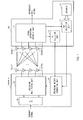
- FIG. 1 is a conceptual diagram illustrating a MIMO system applied to the communication control method according to the present invention.
- each of the base station apparatus eNodeB and the user equipment UE has eight antennas.
- the mobile terminal device UE measures a channel variation amount using the receive signals from each antenna and selects a precoding matrix indicator (PMI) and a rank indicator (RI) corresponding to the phase/amplitude control amount (precoding weight) exhibiting a maximum throughput (or maximum receive signal to interference and noise ratio (SINR)) after combining the transmit data from each transmit antenna of the radio base station apparatus eNodeB base on the measured channel variation amount.
- PMI precoding matrix indicator
- RI rank indicator
- the selected PMI and RI are fed back to the radio base station apparatus eNodeB along with the channel quality indicator (CQI) in uplink.
- CQI channel quality indicator
- the radio base station apparatus eNodeB performs precoding for the transmit data based on the PMI and the RI fed back from the mobile terminal device UE and transmits information from each antenna.
- a signal separation/decoding unit 11 separates and decodes the control channel signal and the data channel signal contained in the receive signal received through the receive antennas RX#1 to RX#8. As the signal separation/decoding unit 11 performs the decoding process, the data channel signal for the mobile terminal device UE is reproduced.
- the PMI selection unit 12 selects the PMI depending on the channel condition estimated by a channel estimation unit (not illustrated). In this case, the PMI selection unit 12 selects an optimal PMI from the codebook 13 including a plurality of N existing precoding weights defined for each rank in both the mobile terminal device UE and the radio base station apparatus eNodeB and the PMI corresponding to the precoding matrix.
- the RI selection unit 14 selects the RI depending on the channel condition estimated by the channel estimation unit. The PMI and the RI are transmitted to the radio base station apparatus eNodeB along with the channel quality indicator (CQI) as feedback information.
- CQI channel quality indicator
- the precoding weight generating unit 21 generates the precoding weight based on the PMI and the RI fed back from the mobile terminal device UE.
- the precoding multiplying unit 22 controls (shifts) the phase/amplitude for each transmit antenna TX#1 to TX#8 by multiplying the precoding weight by the transmit signal converted in parallel by the serial/parallel conversion unit (S/P) 23. As a result, the phase/amplitude-shifted transmit data are transmitted from eight transmit antennas TX#1 to TX#8.
- the upper limit of the number of overall streams (ranks) is set to 4, the maximum number of multiplexed streams per user equipment UE is set to 2, and the maximum number of multiplexed user equipments UE is set to 4 in downlink MU-MIMO transmission.
- the downlink MU-MIMO there may be a case where two SU-MIMO streams are transmitted to each of the mobile terminal devices UE#1 and UE#2 as illustrated in FIG. 2A or a case where a single stream is transmitted to each of the mobile terminal devices UE#1, UE#2, UE#3, and UE#4 as illustrated in FIG. 2B .
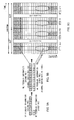
- FIGS. 3A and 3B are diagrams illustrating a feedback method of feedback information from the mobile terminal device UE to the radio base station apparatus eNodeB using physical uplink control channel (PUCCH) in downlink MIMO transmission.
- FIGS. 3A and 3B illustrate a case where the feedback information is fed back periodically (hereinafter, referred to as periodic feedback).
- the feedback information (such as PMI/CQI and RI) is fed back using PUCCH.
- WBPMI, WBCQI, and RI are fed back using different subframes (or different transmission time intervals (TTI)).
- TTI transmission time intervals
- a feedback mode of the channel information of PUCCH is set to mode 1-0(1-1), and the WBPMI/WBCQI period is set to 5 subframes.
- the RI period is set to twice the WBPMI/WBCQI period (10 subframes), and the subframe used to feed back the RI is offset from the subframe used to feed back the PMI/CQI by 2 subframes.
- PMI/CQI and RI are coded and fed back independently from each other.
- the feedback information (such as PMI/CQI and RI) is fed back using PUCCH.
- WBPMI, WBCQI, RI, and SBCQI are fed back using different subframes (TTI).
- a feedback mode of the channel information of PUCCH is set to mode 1-1(2-1), and the WBPMI/WBCQI period is set to 2 subframes.
- the RI period is set to five times the WBPMI/WBCQI period (10 subframes), and the subframe used to feed back the RI is offset from the subframe used to feed back the WBPMI/WBCQI by 1 subframe.
- the number of subbands (bandwidth part (BP) number) is set to 2
- the subframe used to feed back the subband CQI is offset from the subframe used to feed back WBPMI/WBCQI by 2 subframes, and the subband CQI of the same subband is fed back twice during the WBPMI/CQI feedback period.
- WBPMI/WBCQI, RI, and SBCQI are coded and fed back independently from each other.
- FIG. 4 illustrates a case where the feedback information is fed back aperiodically (hereinafter, referred to as "aperiodic feedback").
- the feedback information (such as PMI/CQI and RI) is fed back using the physical uplink shared channel (PUSCH) in response to an uplink-granted trigger signal coming from the base station apparatus eNodeB.
- PUSCH physical uplink shared channel
- PMI/CQI and RI are fed back using different resource elements (RE) within the same subframe (TTI).
- RE resource elements
- TTI subframe
- PMI/CQI and RI are coded and fed back independently from each other.
- the PMI/CQI and the RI are coded independently from each other because the RI requires a receive quality higher than that of the PMI/CQI. That is, the RI is used to determine the number of streams at the time of MIMO transmission and requires a receive quality higher than that of the PMI/CQI used to determine the modulation and coding scheme (MCS) or the precoding weight. For this reason, the RI is coded at a coding rate lower than that of the PMI/CQI.
- MCS modulation and coding scheme
- double codebooks two codebooks (hereinafter appropriately referred to as double codebooks) are provided in both the mobile terminal device UE and the radio base station apparatus eNodeB, and feedback information is fed back for a different period, as a technique for reducing a quantization error in the quantization process of the mobile terminal device UE at the time of MU-MIMO transmission and reducing a feedback information amount for the radio base station apparatus eNodeB.
- one of the codebooks is used as a wideband/long-period codebook, and the other codebook is used as a subband/short-period codebook.
- the double codebooks due to the double codebooks, it is possible to increase an effective size of the codebook. Therefore, it is anticipated that the quantization error in the quantization process of the mobile terminal device UE is reduced.
- the wideband/long-period codebook is not required to feed back the feedback information frequently, compared to the subband/short-period codebook. Therefore, it is anticipated that the feedback information is reduced.
- Each of the first PMI selected from the codebook W1 and the second PMI selected from the codebook W2 is fed back from the mobile terminal device to the radio base station apparatus.
- a precoder such as a precoder corresponding to the first PMI and a precoder corresponding to the second PMI is generated, and downlink MIMO transmission is performed using this precoder.
- the precoder for downlink MIMO transmission may be obtained through a Kronecker product between the precoder corresponding to the first PMI and the precoder corresponding to the second PMI.
- the inventors achieved the invention described below by making a diligent investigation on how to feed back the precoder selected from the double codebooks in a case where double codebooks are used for the downlink MIMO transmission in this manner.
- the precoder (first and second PMIs) selected from the double codebooks W1 and W2 is fed back on PUSCH.
- the first PMI selected from the first codebook for wideband/long-period and the second PMI selected from the second codebook for subband/short-period are individually channel-coded, and the individually channel-coded first and second PMIs are transmitted to the radio base station apparatus on PUSCH.
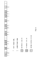
- the first PMI be channel-coded at a channel coding rate lower than that of the second PMI ( FIG. 5B ). Since the first PMI is selected from the first codebook for long-period, if the first PMI is erroneous, it is conceived that the erroneous state (error propagation) is maintained until the next first PMI is fed back (for a relatively long time). In this regard, an error in the first PMI is suppressed by channel-coding the first PMI at a channel coding rate lower than that of the second PMI, so that it is possible to prevent the first PMI from having an erroneous state for a long time.
- the second PMI be channel-coded at a channel coding rate lower than that of the first PMI.
- the second PMI selected from the codebook W2 for subband/short-period since the second PMI selected from the codebook W2 for subband/short-period is used, it is preferable that the second PMI be channel-coded at a low channel coding rate so as to prevent an error.
- the channel coding rates of the first and second PMIs be determined based on the RI. Since the RI is determined based on a spatial correlation, it is possible to optimize the feedback-amount/codebook for each rank depending on the spatial correlation by determining the channel coding rate based on the RI. For example, in the case of a low rank, the spatial correlation is high, so that the channel coding rate of the PMI (particularly, first PMI) is lowered.
- the first and second PMIs subjected to the channel coding are allocated to different positions in the resource block allocated to a user as illustrated in FIG. 5C .
- the first PMI is allocated to the vicinity of the RI
- the second PMI is allocated to the vicinity of the CQI. That is, since the first PMI has a long period, it is necessary to perform the feedback with high performance. For this reason, it is preferable that the first PMI be allocated to the vicinity of the reference signal (demodulation reference signal (DMRS)), that is, the vicinity of RI or ACK/NACK.
- DMRS demodulation reference signal
- the second PMI is allocated to the vicinity of CQI.
- the first PMI and the CQI may be joint-coded, or the second PMI and the CQI (SBCQI or WBCQI) may be joint-coded as illustrated in FIG. 5A .
- the first PMI and the CQI corresponding to the first PMI may be joint-coded, or the second PMI and the CQI corresponding to the second PMI may be joint-coded.
- the first PMI and the RI may be joint-coded.
- the trigger signal used to feed back the information of the codebook W1 and the trigger signal used to feed back the information of the codebook W2 are individually defined.
- the radio base station apparatus individually generates the first trigger signal for the first PMI selected from the first codebook for wideband/long-period and the second trigger signal for the second PMI selected from the second codebook for subband/short-period, and the individually generated first and second trigger signals are transmitted to the mobile terminal device on an uplink grant as illustrated in FIG. 6 .
- the first PMI selected from the first codebook and the second PMI selected from the second codebook based on the first and second trigger signals from the radio base station apparatus on PUSCH the first and second PMIs are allocated to subframes, and the first and second PMIs are transmitted to the radio base station apparatus on PUSCH.
- the first PMI and the CQI (SBCQI or WBCQI) corresponding to the first PMI be allocated to the same subframe
- the second PMI and the CQI (SBCQI or WBCQI) corresponding to the second PMI be allocated to the same subframe.
- the downlink MIMO transmission precoder is obtained from a product or a Kronecker product between the precoder corresponding to the first PMI and the precoder corresponding to the second PMI
- the first PMI and the CQI corresponding to the first PMI be allocated to the same subframe
- the second PMI and the CQI corresponding to the product or Kronecker product between the first and second PMIs be allocated to the same subframe.
- the second PMI is selected by assuming a particular first PMI, the CQI for the product or Kronecker product is fed back.
- it is possible to improve a resistance to a feedback error that is, alleviate influence of a throughput characteristic deterioration.
- the first and second PMIs are fed back using the same subframe (the first and second PMIs are allocated to the same subframe)
- the first PMI and the CQI corresponding to a product or a Kronecker product of the PMIs be allocated to subframes.
- the precoder selected from the double codebooks W1 and W2 (first and second PMIs) is fed back on PUCCH.
- the mobile terminal device selects the first PMI from the first codebook for wideband/long-period and selects the second PMI from the second codebook for subband/short-period having a subband size set to a relatively wide bandwidth.
- the first and second PMIs are allocated to subframes and are transmitted to the radio base station apparatus on PUCCH.
- the subband size of the codebook W2 is made to be equal to the entire system band (or component carrier bandwidth). That is, the codebook is set so as to support only the wideband.
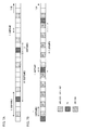
- the first and second PMIs and the wideband CQI be allocated to the same subframe.
- the second PMI and the wideband CQI be allocated to the same subframe, and the first PMI be allocated to subframes other than the aforementioned subframe. As a result, it is possible to suppress the feedback overhead in the vicinity of each subframe to the minimum.
- the subband size of the codebook W2 may be equal to the subband size of the CQI.
- the first PMI and the wideband CQI are allocated to the same subframe, and the second PMI and the subband CQI of the subband corresponding to the second PMI are allocated to the same subframe.
- FIG. 9 is a diagram illustrating a configuration of the mobile communication system 1 having the mobile terminal device 10 and the radio base station apparatus 20 according to an embodiment of the present invention.
- the mobile communication system 1 of FIG. 9 is, for example, an LTE system or a SUPER-3G system.
- the mobile communication system 1 may be called an IMT-Advanced or 4G.
- the mobile communication system 1 includes a radio base station apparatus 20 and a plurality of mobile terminal devices 10 (including 10 1 , 10 2 , 10 3 , ..., and 10 n , where n denotes an integer greater than 0) that communicate with the radio base station apparatus 20.
- the radio base station apparatus 20 is connected to an upper-layer station apparatus 30, which is connected to a core network 40.
- the mobile station apparatus 10 communicates with the base station apparatus 20 in a cell 50.
- the upper-layer station apparatus 30 may include, for example, but not limited to, an access gateway apparatus, a radio network controller (RNC), a mobility management entity (MME), and the like.
- RNC radio network controller
- MME mobility management entity
- each mobile terminal device 10 1 , 10 2 , 10 3 , ..., and 10 n have the same configuration, function and condition, the mobile terminal device will be denoted by reference numeral 10 in the following description unless specified otherwise.
- the mobile terminal device 10 wirelessly communicates with the radio base station apparatus 20.
- the mobile terminal device 10 may be called a user equipment UE, including both a mobile terminal device and a fixed terminal apparatus.
- orthogonal frequency division multiple access is employed in downlink
- SC-FDMA single carrier frequency division multiple access
- OFDMA orthogonal frequency division multiple access
- SC-FDMA single carrier frequency division multiple access
- OFDMA a multiple carrier transmission scheme is employed, in which a frequency band is divided into a plurality of narrow frequency bands (subcarriers), and communication is performed by mapping data to each subcarrier.
- SC-FDMA a single carrier transmission scheme is employed, in which interference between terminals is alleviated by dividing a system band into bands including a single or a series of resource blocks for each terminal and causing a plurality of terminals to use different bands.
- a communication channel in an LTE system In downlink, the PDSCH shared by each mobile station apparatus 10 and the downlink L1/L2 control channels (PDCCH, PCFICH, and PHICH) are used. Using this PDSCH, user data, that is, a typical data signal is transmitted. The transmit data are included in this user data. In addition, CC allocated to the mobile terminal device 10 from the radio base station apparatus 20 or scheduling information is notified to the mobile terminal device 10 through the L1/L2 control channel.
- PDCH downlink L1/L2 control channels
- the physical uplink shared channel (PUSCH) shared by each mobile terminal device 10 and the physical uplink control channel (PUCCH) as the uplink control channel are used.
- PUSCH physical uplink shared channel
- PUCCH physical uplink control channel
- user data are transmitted.
- PUCCH the downlink channel quality indicator (CQI) and the like are transmitted.
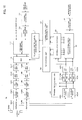
- FIG. 10 is a block diagram illustrating a configuration of the mobile terminal device 10 according to the present embodiment.
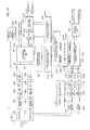
- FIG. 11 is a block diagram illustrating a configuration of the radio base station apparatus 20 according to the present embodiment.
- the configurations of the mobile terminal device 10 and the radio base station apparatus 20 of FIGS. 10 and 11 are simplified for description of the present invention, and it is assumed that they include elements of a typical radio base station apparatus and a typical mobile terminal device, respectively.
- the transmit signal transmitted from the radio base station apparatus 20 is received by the antennas 1 to N RX and is electrically divided by a duplexer 101#1 to 101#N into a transmit path and a receive path. Then, they are output to the RF receive circuits 102#1 to 102#N.
- the RF receive circuits 102#1 to 102#N perform a frequency conversion process for converting the radio frequency signal to a baseband signal, and then, they are output to the receive timing estimation unit 105 and the CP removal units 103#1 to 103#N.
- the receive timing estimation unit 105 estimates a receive timing using the receive signal subjected to the frequency conversion process and outputs the receive timing to the CP removal units 103# to 103#N.
- the CP removal units 103#1 to 103#N remove a cyclic prefix (CP), and the fast Fourier transform (FFT) units 104#1 to 104#N perform Fourier transform to transform a time series signal to a frequency domain signal.
- the receive signal transformed to the frequency domain signal is output to the channel estimation unit 106 and the data channel signal demodulation unit 107.
- the channel estimation unit 106 estimates the channel condition from the reference signal included in the receive signal output from the FFT units 104#1 to 104#N and notifies the data channel signal demodulation unit 107 of the estimated channel condition.
- the data channel signal demodulation unit 107 demodulates the data channel signal based on the notified channel condition.
- the demodulated data channel signal is channel-demodulated by the channel demodulation unit 108 and is reproduced by a user_#k signal.
- the channel quality (CQI) measurement unit 110 measures the channel quality from the channel condition notified from the channel estimation unit 106. Specifically, the channel quality measurement unit 110 measures the CQI based on the channel condition notified from the channel estimation unit 106 and notifies the feedback control signal generating unit 111 of the CQI. The channel quality measurement unit 110 selects the first PMI selected from the first codebook W1 for wideband/long-period, the second PMI selected from the second codebook W2 for subband/short-period, or the CQI corresponding to the Kronecker product between the first and second PMIs.
- the PMI selection unit 109 selects the PMI from the channel condition notified from the channel estimation unit 106.
- the PMI selection unit 109 has double codebooks, that is, including the first codebook for wideband/long-period and the second codebook for subband/short-period.
- the PMI selection unit 109 selects the first PMI from the first codebook and the second PMI from the second codebook.
- the PMI selection unit 109 notifies the feedback control signal generating unit 111 of the selected first and second PMIs.
- the RI is selected depending on the channel condition estimated by the channel estimation unit 106, and the selected RI is notified to the feedback control signal generating unit 111.
- the feedback control signal generating unit 111 serving as a control signal generating means generates a control signal (such as PUCCH signal) used to feed back the notified PMI, CQI, and RI to the base station apparatus 20.
- the feedback control signal generating unit 111 performs channel-coding and data-modulation of information of the PMI and the CQI of the first and second codebooks W1 and W2 for performing the feedback on PUCCH or PUSCH.
- This channel coding is performed according to the first aspect described above. That is, the first and second PMIs are channel-coded individually.
- the control signal generated by the feedback control signal generating unit 111 or the PMI or CQI subjected to the channel-coding is output to the multiplexer (MUX) 115.
- MUX multiplexer
- the transmit_data_#k for user_#k transmitted from the upper layer are channel-coded by the channel coding unit 112 and then, the coded data are modulated by the data modulation unit 113.
- a discrete Fourier transform unit (not illustrated) performs inverse Fourier transform for the transmit_data_#k modulated by the data modulation unit 113 to transform the time series signal to the frequency domain signal, and the transformed signal is output to the subcarrier mapping unit (not illustrated).
- the subcarrier mapping unit performs mapping of the transmit_data_#k to the subcarriers based on the schedule information instructed from the radio base station apparatus 20. In this case, the subcarrier mapping unit performs mapping (multiplexing) of the reference_signal_#k generated by a reference signal generating unit (not illustrated) along with the transmit_data_#k to the subcarriers. In this manner, the transmit_data_#k mapped to the subcarriers is output to the precoding multiplying unit 114.
- the precoding multiplying unit 114 shifts the phase and/or amplitude of the transmit_data_#k for each receive antenna 1 to N RX based on the precoding weight corresponding to the PMI.
- the transmit_data_#k of which the phase and/or amplitude have been shifted by the precoding multiplying unit 114 are output to the multiplexer (MUX) 115.
- the multiplexer (MUX) 115 combines the transmit_data_#k of which the phase and/or phase have been shifted and the control signal generated by the feedback control signal generating unit 111 to generate transmit signals for each receive antennas 1 to N RX .
- the first and second PMIs and the CQI are mapped to different positions within the allocation resource. This mapping (multiplexing) is performed according to the first aspect described above. On the contrary, in a case where the first and second PMIs are fed back on PUCCH, the first and second PMIs and the CQI are allocated to subframes. This mapping (multiplexing) is performed according to the third aspect described above.
- the transmit signal generated by the multiplexer (MUX) 115 is subjected to discrete Fourier transform (DFT) in discrete Fourier transform units 116#1 to 116#N to transform the time series signal to the frequency domain signal.
- DFT discrete Fourier transform
- the frequency domain signal is allocated to a frequency band orthogonal to those of other UEs through subcarrier mapping (not illustrated).
- IFFT inverse fast Fourier transform
- CP adding units 118#1 to 118#N add the CONVEX PORTION (CP) to the time domain signal and outputs the result to the RF transmit circuits 119#1 to 119#N.
- the RF transmit circuits 119#1 to 119#N perform the frequency conversion process for conversion to the radio frequency band, and the radio frequency signal is output to the antennas 1 to N RX through the duplexers 101#1 to 101#N and is transmitted to the radio base station apparatus 20 from the antennas 1 to N RX in uplink.
- the RF transmit circuits 119#1 to 119#N, the duplexers 101#1 to 101#N, and the antennas 1 to N RX constitute a transmission means for transmitting the control signal.
- the first PMI selected from the first codebook W1 for wideband/long-period and the second PMI selected from the second codebook W2 for subband/short-period are individually channel-coded, and the individually channel-coded first and second PMIs are transmitted to the radio base station apparatus on PUSCH or PUCCH. Therefore, it is possible to effectively feed back the PMI by selecting a precoder using double codebooks W1 and W2 in downlink MIMO transmission.
- the radio base station apparatus 20 of FIG. 11 transmits the transmit_data_#1 to the transmit_data_#k for user_#1 to user_#k to the corresponding channel coding units 201#1 to 201#k.
- the transmit_data_#1 to the transmit_data_#k are channel-coded using the channel coding units 201#1 to 201#k and are output to the data modulation units 202#1 to 202#k for data modulation.
- the transmit_data_#1 to the transmit_data_#k subjected to the data modulation in the data modulation units 202#1 to 202#k are subjected to inverse discrete Fourier transform in the discrete Fourier transform unit (not illustrated) for conversion from the time series signal to the frequency domain signal, and the frequency domain signal is output to the precoding multiplying units 203#1 to 203#k.
- the precoding multiplying units 203#1 to 203#k shift the phase and/or amplitude of the transmit_data_#1 to the transmit_data_#k for each antenna 1 to N TX (weighting of the antennas 1 to N TX through the precoding) based on the precoding weight provided from the precoding weight generating unit 220 described below.
- the transmit_data_#1 to the transmit_data_#k of which the phase and/or amplitude are shifted by the precoding multiplying units 203#1 to 203#k are output to the multiplexer (MUX) 205.
- MUX multiplexer
- the control signal generating units 204#1 to 204#k generates the control signal (PDCCH) based on the number of multiplexed users from the scheduler 201.
- the control signal generating units 204#1 to 204#k perform feedback control of the first and second PMIs using 2 bits of the trigger signal (first and second trigger signals) within the uplink grant. That is, the control signal generating units 204#1 to 204#k individually generate the first trigger signal for the first PMI selected from the first codebook W1 for wideband/long-period and the second trigger signal for the second PMI selected from the second codebook W2 for subband/short-period.
- the control signal generating units 204#1 to 204#k output each PDCCH and the first and second trigger signals to the multiplexer (MUX) 205.
- MUX multiplexer
- the multiplexer (MUX) 205 combines the transmit_data_#1 to the transmit_data_#k of which the phase and/or amplitude are shifted, each PDCCH generated by the control signal generating units 204#1 to 204#k, and the first and second trigger signals to generate transmit signals for each transmit antennas 1 to N TX .
- the transmit signal generated by the multiplexer (MUX) 205 is subjected to the discrete Fourier transform in the discrete Fourier transform (DFT) units 206#1 to 206#k to transform the time series signal to the frequency domain signal.
- the inverse fast Fourier transform (IFFT) units 207#1 to 207#k perform inverse fast Fourier transform to transform the frequency domain signal to the time domain signal.
- the CP adding units 208#1 to 208#k add the CP, and the resultant signal is output to the RF transmit circuits 209#1 to 209#k.
- the signal After the frequency conversion process for conversion to the radio frequency band in the RF transmit circuits 209#1 to 209#N, the signal is output to the antennas 1 to N TX through the duplexers 210#1 to 210#N. Then, the signal is transmitted from the antennas 1 to N TX to the mobile terminal device 10 in downlink.
- the RF transmit circuits 209#1 to 209#k, the duplexers 210#1 to 210#N, and the antennas 1 to N TX constitute a transmit means for transmitting the control signal.
- the transmit signal transmitted from the mobile terminal device 10 in uplink is received by the antennas 1 to N TX .
- the received signal is electrically divided by the duplexers 210#1 to 210#N into the transmit path and the receive path, and then, the divided signals are output to the RF receive circuits 211#1 to 211#N.
- the RF receive circuits 211#1 to 211#N perform a frequency conversion process for converting the radio frequency signal to the baseband signal.
- the signal is output to the receive timing estimation unit 221 and the CP removal units 212#1 o 212#N.
- the receive timing estimation unit 221 estimates the receive timing using the receive signal subjected to the frequency conversion process, and the receive timing is output to the CP removal units 212#1 to 212#N.
- the CP is removed by the CP removal units 212#1 to 212#N, and Fourier transform is performed by the fast Fourier transform (FFT) units 213#1 to 213#N so that the time series signal is transformed to the frequency domain signal.
- the inverse discrete Fourier transform IDFT) units 214#1 to 214#N perform the inverse discrete Fourier transform to transform the frequency domain signal to the time domain signal.
- the receive signal converted to the time domain signal is output to the channel estimation units 215#1 to 215#N and the data channel signal demodulation units 216#1 to 216#N.
- the channel estimation units 215#1 to 215#N estimate the channel condition from the reference signal contained in the receive signal output from the IDFT units 214#1 to 214#N, and the estimated channel condition is notified to the data channel signal demodulation units 216#1 to 216#N.
- the data channel signal demodulation units 216#1 to 216#N demodulate the data channel signal based on the notified channel condition.
- the demodulated data channel signal is channel-decoded by the channel decoding units 217#1 to 217#N and is reproduced to user signals user_#1 to user_#k.
- the antennas 1 to N TX , the duplexers 210#1 to 210#N, and the RF receive circuits 211#1 to 211#N constitute a receive means for receiving the control signal.
- the PMI/CQI/RI information demodulation units 218#1 to 218#N demodulate information regarding channels (channel information), for example, feedback information such as CQI, PMI, and RI notified using PDCCH from the information included in each control channel signal (e.g., PUCCH).
- the information demodulated by the PMI/CQI/RI information demodulation units 218#1 to 218#N is output to the CQI information extraction units 222#1 to 222#N and the PMI information extraction units 219#1 to 219#N, respectively.
- the CQI information extraction units 222#1 to 222#N extract the CQI information from the information demodulated by the PMI/CQI/RI information demodulation units 218#1 to 218#N.
- the extracted CQI is output to the data modulation units 202#1 to 202#k and the channel coding units 201#1 to 201#k, respectively.
- the PMI information extraction units 219#1 to 219#N extract the PMI information from the information demodulated by the PMI/CQI/RI information demodulation units 218#1 to 218#N.
- the PMI information refers to the first PMI selected from the first codebook W1 and the second PMI selected from the second codebook W2.
- the PMI-extracted first and second PMIs are output to the precoding weight generating unit 220.
- the precoding weight generating unit 220 serving as a weight generating means generates the precoding weight representing the phase and/or amplitude shift amount for the transmit_data#1 to the transmit_data_#k based on the first and second PMIs output from the PMI information extraction units 219#1 to 219#N and the RI. Each of the generated precoding weights is output to the precoding multiplying units 203#1 to 203#k and is used in the precoding of the transmit_data#1 to transmit_data_#k.
- the radio base station apparatus 20 individually generates the first trigger signal for the first PMI selected from the first codebook for wideband/long-period and the second trigger signal for the second PMI selected from the second codebook for subband/short-period and transmits the individually generated first and second trigger signals to the mobile terminal device on an uplink grant. Therefore, it is possible to effectively feedback the PMI by selecting the precoder using double codebooks W1 and W2 in downlink MIMO transmission.
Landscapes
- Engineering & Computer Science (AREA)
- Computer Networks & Wireless Communication (AREA)
- Signal Processing (AREA)
- Physics & Mathematics (AREA)
- Mathematical Physics (AREA)
- Power Engineering (AREA)
- Mobile Radio Communication Systems (AREA)
- Radio Transmission System (AREA)
Abstract
Description
- The present invention relates to a mobile terminal device and a radio base station apparatus, and more particularly, to a mobile terminal device and a radio base station apparatus employed in multiple antenna transmission.
- In a universal mobile telecommunications system (UMTS) network, high speed downlink packet access (HSDPA) or high speed uplink packet access (HSUPA) is employed in order to improve spectrum efficiency and a data rate so that characteristics of a wideband code division multiple access (W-CDMA) based system can be maximized. In such an UMTS network technology, long term evolution (LTE) has been discussed to obtain a higher data rate, a lower delay, and the like.
- In a 3GPP system, a fixed band of 5 MHz is used in general to implement a transmission rate of 2 Mbps at maximum in downlink. Meanwhile, in an LTE system, transmission rates of 300 Mbps in downlink and 75 Mbps in uplink at maximum can be implemented using variable bandwidth between 1.4 MHz and 20 MHz. In addition, in a UMTS network, in order to obtain a wider bandwidth and a faster transmission rate, a post-LTE system is also discussed (e.g., LTE-Advanced (LTE-A)). For example, in LTE-A, it is anticipated that the maximum system bandwidth of 20 MHz in the LTE specification is expanded to, approximately, 100 MHz. In addition, it is anticipated that the maximum number of transmit antennas set to 4 in the LTE specification is expanded to 8.
- In an LTE system, data are transmitted/received using a plurality of antennas, and a multiple input multiple output (MIMO) system has been proposed as a radio communication technique for improving a data rate (spectrum efficiency) (see e.g., Non-patent Literature 1). In the MIMO system, a plurality of transmit/receive antennas are provided in a transceiver, and different transmission information sequences are simultaneously transmitted from different transmit antennas. Meanwhile, at the receiver side, the information sequences transmitted simultaneously are separately detected in consideration of a fact that different fading variations are generated between transmit/receive antennas, so that it is possible to increase a data rate (spectrum efficiency) .
- In an LTE system, there are defined single-user MIMO (SU-MIMO) in which overall transmission information sequences simultaneously transmitted from different transmit antennas belong to the same user and multiple-user MIMO (MU-MIMO) in which transmission information sequences simultaneously transmitted from different transmit antennas belong to different users. In both the SU-MIMO transmission and the MU-MIMO transmission, an optimal preceding matrix indicator (PMI) is selected from a codebook in which a plurality of phase/amplitude control amounts (precoding matrix (precoding weight)) to be set for the antennas of the transmitter at the receiver side and a plurality of PMIs corresponding to the precoding matrix are defined for each rank, and the optimal PMI is fed back to the transmitter. In addition, a rank indicator (RI) indicating the optimal rank is selected and fed back to the transmitter. At the transmitter side, the precoding weights for each transmit antenna are specified based on the PMI and the RI fed back from the receiver, and the precoding is performed, so that the transmission information sequences are transmitted.
- [Non-patent Literature 1] 3GPP TR 25.913 "Requirements for Evolved UTRA and Evolved UTRAN"
- In LTE-A, it is determined that the mobile terminal device feeds back the PMI, and the precoder selected by the mobile terminal device is generated by selecting one of double codebooks W1 and W2. It is necessary to investigate how to feed back the precoder selected from the two codebooks W1 and W2.
- The present invention has been made in view of the aforementioned problems, and an aim thereof is to provide a mobile terminal device and a radio base station apparatus capable of effectively feeding back PMI by selecting the precoder using double codebooks W1 and W2 in downlink MIMO transmission.
- According to an aspect of the present invention, there is provided a mobile terminal device including: a feedback control signal generating section that individually performs channel coding for a first precoding matrix indicator (PMI) selected from a first codebook for wideband/long-period and a second PMI selected from a second codebook for subband/short-period; and a transmit section that transmits the individually channel-coded first and second PMIs to a radio base station apparatus on a physical uplink shared channel (PUSCH).
- According to an aspect of the present invention, there is provided a mobile terminal device including: a PMI selection section that selects the first PMI from a first codebook for wideband/long-period and selects the second PMI from a second codebook for subband/short-period in which a subband size is set to a relatively wider bandwidth; a multiplexing section that allocates the first and second PMIs to subframes; and a transmit section that transmits the first and second PMIs to the radio base station apparatus on a physical uplink control channel.
- According to another aspect of the present invention, there is provided a radio base station apparatus including: a control signal generating section that individually generates a first trigger signal for a first PMI selected from a first codebook for wideband/long-period and a second trigger signal for a second PMI selected from a second codebook for subband/short-period; and a transmit section that transmits the individually generated first and second trigger signals to a mobile terminal device on an uplink grant.
- According to the present invention, the first PMI selected from the first codebook for wideband/long-period and the second PMI selected from the second codebook for subband/short-period are individually channel-coded, and the individually channel-coded first and second PMIs are transmitted to the radio base station apparatus on a physical uplink shared channel (PUSCH). Therefore, it is possible to effectively feed back the PMI by selecting a precoder using double codebooks W1 and W2 in downlink MIMO transmission.
-
-
FIG. 1 is a conceptual diagram illustrating a MIMO system applied to a communication control method according to the present invention; -
FIGS. 2A and 2B are diagrams illustrating downlink MIMO transmission in LTE-A; -
FIGS. 3A and 3B are diagrams illustrating a PMI/CQI/RI feedback using PUCCH; -
FIG. 4 is a diagram illustrating a PMI/CQI/RI feedback using PUSCH; -
FIGS. 5A, 5B, and 5C are diagrams illustrating the mobile terminal device according to a first aspect of the present invention; -
FIG. 6 is a diagram illustrating the mobile terminal device according to a second aspect of the present invention; -
FIGS. 7A and 7B are diagrams illustrating the mobile terminal device according to a third aspect of the present invention; -
FIG. 8 is a diagram illustrating the mobile terminal device according to a third aspect of the present invention; - FIG. 9 is a diagram illustrating a configuration of the mobile communication system according to an embodiment of the present invention;
-
FIG. 10 is a block diagram illustrating a configuration of the mobile terminal device according to the embodiment described above; and -
FIG. 11 is a block diagram illustrating a configuration of the radio base station apparatus according to the embodiment described above. - Hereinafter, embodiments of the present invention will be described in detail with reference to the accompanying drawings. First, a precoding in downlink MIMO transmission performed in an LTE-A system will be described based on the MIMO system of
FIG. 1. FIG. 1 is a conceptual diagram illustrating a MIMO system applied to the communication control method according to the present invention. In addition, in the MIMO system ofFIG. 1 , each of the base station apparatus eNodeB and the user equipment UE has eight antennas. - In the precoding on downlink MIMO transmission in the MIMO system of
FIG. 1 , the mobile terminal device UE measures a channel variation amount using the receive signals from each antenna and selects a precoding matrix indicator (PMI) and a rank indicator (RI) corresponding to the phase/amplitude control amount (precoding weight) exhibiting a maximum throughput (or maximum receive signal to interference and noise ratio (SINR)) after combining the transmit data from each transmit antenna of the radio base station apparatus eNodeB base on the measured channel variation amount. In addition, the selected PMI and RI are fed back to the radio base station apparatus eNodeB along with the channel quality indicator (CQI) in uplink. The radio base station apparatus eNodeB performs precoding for the transmit data based on the PMI and the RI fed back from the mobile terminal device UE and transmits information from each antenna. - In the mobile terminal device UE of
FIG. 1 , a signal separation/decoding unit 11 separates and decodes the control channel signal and the data channel signal contained in the receive signal received through the receiveantennas RX# 1 toRX# 8. As the signal separation/decoding unit 11 performs the decoding process, the data channel signal for the mobile terminal device UE is reproduced. ThePMI selection unit 12 selects the PMI depending on the channel condition estimated by a channel estimation unit (not illustrated). In this case, thePMI selection unit 12 selects an optimal PMI from thecodebook 13 including a plurality of N existing precoding weights defined for each rank in both the mobile terminal device UE and the radio base station apparatus eNodeB and the PMI corresponding to the precoding matrix. The RIselection unit 14 selects the RI depending on the channel condition estimated by the channel estimation unit. The PMI and the RI are transmitted to the radio base station apparatus eNodeB along with the channel quality indicator (CQI) as feedback information. - Meanwhile, in the radio base station apparatus eNodeB of
FIG. 1 , the precodingweight generating unit 21 generates the precoding weight based on the PMI and the RI fed back from the mobile terminal device UE. Theprecoding multiplying unit 22 controls (shifts) the phase/amplitude for each transmitantenna TX# 1 toTX# 8 by multiplying the precoding weight by the transmit signal converted in parallel by the serial/parallel conversion unit (S/P) 23. As a result, the phase/amplitude-shifted transmit data are transmitted from eight transmitantennas TX# 1 to TX#8. - However, according to agreement of the LTE-A system, the upper limit of the number of overall streams (ranks) is set to 4, the maximum number of multiplexed streams per user equipment UE is set to 2, and the maximum number of multiplexed user equipments UE is set to 4 in downlink MU-MIMO transmission. For this reason, in the downlink MU-MIMO, there may be a case where two SU-MIMO streams are transmitted to each of the mobile terminal
devices UE# 1 andUE# 2 as illustrated inFIG. 2A or a case where a single stream is transmitted to each of the mobile terminaldevices UE# 1,UE# 2,UE# 3, andUE# 4 as illustrated inFIG. 2B . - Here, description will be made for a feedback method of feedback information including channel information (PMI/CQI/RI) from the mobile terminal device to the radio base station apparatus eNodeB in such downlink MIMO transmission.
FIGS. 3A and 3B are diagrams illustrating a feedback method of feedback information from the mobile terminal device UE to the radio base station apparatus eNodeB using physical uplink control channel (PUCCH) in downlink MIMO transmission.FIGS. 3A and 3B illustrate a case where the feedback information is fed back periodically (hereinafter, referred to as periodic feedback). - In the periodic feedback, there are a mode in which wideband (WB) CQI, WBPMI, and RI are fed back using separate subframes as illustrated in
FIG. 3A and a mode in which WBCQI, WBPMI, RI, and subband (SB) CQI are fed back using separate subframes as illustrated inFIG. 3B . - In the mode illustrated in
FIG. 3A , the feedback information (such as PMI/CQI and RI) is fed back using PUCCH. As illustrated inFIG. 3A , WBPMI, WBCQI, and RI are fed back using different subframes (or different transmission time intervals (TTI)). InFIG. 3A , a feedback mode of the channel information of PUCCH is set to mode 1-0(1-1), and the WBPMI/WBCQI period is set to 5 subframes. In addition, the RI period is set to twice the WBPMI/WBCQI period (10 subframes), and the subframe used to feed back the RI is offset from the subframe used to feed back the PMI/CQI by 2 subframes. In this case, PMI/CQI and RI are coded and fed back independently from each other. - Similarly, in the mode illustrated in
FIG. 3B , the feedback information (such as PMI/CQI and RI) is fed back using PUCCH. As illustrated inFIG. 3B , WBPMI, WBCQI, RI, and SBCQI are fed back using different subframes (TTI). InFIG. 3B , a feedback mode of the channel information of PUCCH is set to mode 1-1(2-1), and the WBPMI/WBCQI period is set to 2 subframes. In addition, the RI period is set to five times the WBPMI/WBCQI period (10 subframes), and the subframe used to feed back the RI is offset from the subframe used to feed back the WBPMI/WBCQI by 1 subframe. Furthermore, the number of subbands (bandwidth part (BP) number) is set to 2, the subframe used to feed back the subband CQI is offset from the subframe used to feed back WBPMI/WBCQI by 2 subframes, and the subband CQI of the same subband is fed back twice during the WBPMI/CQI feedback period. In this case, WBPMI/WBCQI, RI, and SBCQI are coded and fed back independently from each other. -
FIG. 4 illustrates a case where the feedback information is fed back aperiodically (hereinafter, referred to as "aperiodic feedback"). In the aperiodic feedback, the feedback information (such as PMI/CQI and RI) is fed back using the physical uplink shared channel (PUSCH) in response to an uplink-granted trigger signal coming from the base station apparatus eNodeB. As illustrated inFIG. 4 , PMI/CQI and RI are fed back using different resource elements (RE) within the same subframe (TTI). In this case, similar to the periodic feedback, PMI/CQI and RI are coded and fed back independently from each other. - The PMI/CQI and the RI are coded independently from each other because the RI requires a receive quality higher than that of the PMI/CQI. That is, the RI is used to determine the number of streams at the time of MIMO transmission and requires a receive quality higher than that of the PMI/CQI used to determine the modulation and coding scheme (MCS) or the precoding weight. For this reason, the RI is coded at a coding rate lower than that of the PMI/CQI.
- In the MIMO system of the LTE-A scheme, a method has been discussed, in which two codebooks (hereinafter appropriately referred to as double codebooks) are provided in both the mobile terminal device UE and the radio base station apparatus eNodeB, and feedback information is fed back for a different period, as a technique for reducing a quantization error in the quantization process of the mobile terminal device UE at the time of MU-MIMO transmission and reducing a feedback information amount for the radio base station apparatus eNodeB.
- In this double codebook MIMO system, one of the codebooks is used as a wideband/long-period codebook, and the other codebook is used as a subband/short-period codebook. In this MIMO system, due to the double codebooks, it is possible to increase an effective size of the codebook. Therefore, it is anticipated that the quantization error in the quantization process of the mobile terminal device UE is reduced. In addition, the wideband/long-period codebook is not required to feed back the feedback information frequently, compared to the subband/short-period codebook. Therefore, it is anticipated that the feedback information is reduced.
- Each of the first PMI selected from the codebook W1 and the second PMI selected from the codebook W2 is fed back from the mobile terminal device to the radio base station apparatus. In the radio base station apparatus, a precoder such as a precoder corresponding to the first PMI and a precoder corresponding to the second PMI is generated, and downlink MIMO transmission is performed using this precoder. In this case, the precoder for downlink MIMO transmission may be obtained through a Kronecker product between the precoder corresponding to the first PMI and the precoder corresponding to the second PMI.
- The inventors achieved the invention described below by making a diligent investigation on how to feed back the precoder selected from the double codebooks in a case where double codebooks are used for the downlink MIMO transmission in this manner.
- In this aspect, the precoder (first and second PMIs) selected from the double codebooks W1 and W2 is fed back on PUSCH. In this aspect, the first PMI selected from the first codebook for wideband/long-period and the second PMI selected from the second codebook for subband/short-period are individually channel-coded, and the individually channel-coded first and second PMIs are transmitted to the radio base station apparatus on PUSCH.
- In this case, it is preferable that the first PMI be channel-coded at a channel coding rate lower than that of the second PMI (
FIG. 5B ). Since the first PMI is selected from the first codebook for long-period, if the first PMI is erroneous, it is conceived that the erroneous state (error propagation) is maintained until the next first PMI is fed back (for a relatively long time). In this regard, an error in the first PMI is suppressed by channel-coding the first PMI at a channel coding rate lower than that of the second PMI, so that it is possible to prevent the first PMI from having an erroneous state for a long time. - In addition, in a case where an antenna correlation is low as in the SU-MIMO, it is preferable that the second PMI be channel-coded at a channel coding rate lower than that of the first PMI. In SU-MIMO transmission, since the second PMI selected from the codebook W2 for subband/short-period is used, it is preferable that the second PMI be channel-coded at a low channel coding rate so as to prevent an error.
- In addition, it is preferable that the channel coding rates of the first and second PMIs be determined based on the RI. Since the RI is determined based on a spatial correlation, it is possible to optimize the feedback-amount/codebook for each rank depending on the spatial correlation by determining the channel coding rate based on the RI. For example, in the case of a low rank, the spatial correlation is high, so that the channel coding rate of the PMI (particularly, first PMI) is lowered.
- The first and second PMIs subjected to the channel coding are allocated to different positions in the resource block allocated to a user as illustrated in
FIG. 5C . For example, the first PMI is allocated to the vicinity of the RI, and the second PMI is allocated to the vicinity of the CQI. That is, since the first PMI has a long period, it is necessary to perform the feedback with high performance. For this reason, it is preferable that the first PMI be allocated to the vicinity of the reference signal (demodulation reference signal (DMRS)), that is, the vicinity of RI or ACK/NACK. Meanwhile, as illustrated inFIG. 5C , the second PMI is allocated to the vicinity of CQI. - In a case where the first and second PMIs are channel-coded, the first PMI and the CQI (SBCQI or WBCQI) may be joint-coded, or the second PMI and the CQI (SBCQI or WBCQI) may be joint-coded as illustrated in
FIG. 5A . In addition, the first PMI and the CQI corresponding to the first PMI may be joint-coded, or the second PMI and the CQI corresponding to the second PMI may be joint-coded. In addition, the first PMI and the RI may be joint-coded. - In this aspect, when information (PMI) of the double codebooks W1 and W2 is fed back aperiodically on PUSCH using the trigger signal, the trigger signal used to feed back the information of the codebook W1 and the trigger signal used to feed back the information of the codebook W2 are individually defined.
- In this aspect, the radio base station apparatus individually generates the first trigger signal for the first PMI selected from the first codebook for wideband/long-period and the second trigger signal for the second PMI selected from the second codebook for subband/short-period, and the individually generated first and second trigger signals are transmitted to the mobile terminal device on an uplink grant as illustrated in
FIG. 6 . - In this manner, in the mobile terminal device which feeds back, to the radio base station apparatus, the first PMI selected from the first codebook and the second PMI selected from the second codebook based on the first and second trigger signals from the radio base station apparatus on PUSCH, the first and second PMIs are allocated to subframes, and the first and second PMIs are transmitted to the radio base station apparatus on PUSCH.
- In this case, in the mobile terminal device, when two types of CQIs (SBCQI and WBCQI) are used, it is preferable that the first PMI and the CQI (SBCQI or WBCQI) corresponding to the first PMI be allocated to the same subframe, and the second PMI and the CQI (SBCQI or WBCQI) corresponding to the second PMI be allocated to the same subframe. As a result, it is possible to improve a resistance to a feedback error, that is, alleviate influence of the throughput characteristic deterioration.
- In a case where the downlink MIMO transmission precoder is obtained from a product or a Kronecker product between the precoder corresponding to the first PMI and the precoder corresponding to the second PMI, it is preferable that the first PMI and the CQI corresponding to the first PMI be allocated to the same subframe, and the second PMI and the CQI corresponding to the product or Kronecker product between the first and second PMIs be allocated to the same subframe. In this case, since the second PMI is selected by assuming a particular first PMI, the CQI for the product or Kronecker product is fed back. As a result, it is possible to improve a resistance to a feedback error, that is, alleviate influence of a throughput characteristic deterioration.
- In addition, in a case where the first and second PMIs are fed back using the same subframe (the first and second PMIs are allocated to the same subframe), it is preferable that the first PMI and the CQI corresponding to a product or a Kronecker product of the PMIs be allocated to subframes. As a result, it is possible to improve a resistance to a feedback error, that is, alleviate influence of a throughput characteristic deterioration.
- In this aspect, the precoder selected from the double codebooks W1 and W2 (first and second PMIs) is fed back on PUCCH. In this aspect, the mobile terminal device selects the first PMI from the first codebook for wideband/long-period and selects the second PMI from the second codebook for subband/short-period having a subband size set to a relatively wide bandwidth. The first and second PMIs are allocated to subframes and are transmitted to the radio base station apparatus on PUCCH.
- Here, the subband size of the codebook W2 is made to be equal to the entire system band (or component carrier bandwidth). That is, the codebook is set so as to support only the wideband. In this case, as illustrated in
FIG. 7A , it is preferable that the first and second PMIs and the wideband CQI be allocated to the same subframe. As a result, it is possible to suppress increase of the feedback overhead in the vicinity of the subframe to the minimum without increasing the number of feedback subframes. In addition, as illustrated inFIG. 7B , it is preferable that the second PMI and the wideband CQI be allocated to the same subframe, and the first PMI be allocated to subframes other than the aforementioned subframe. As a result, it is possible to suppress the feedback overhead in the vicinity of each subframe to the minimum. - In the aspect in which the precoder (first and second PMIs) selected from the double codebooks W1 and W2 is fed back on PUCCH, the subband size of the codebook W2 may be equal to the subband size of the CQI. In this case, as illustrated in
FIG. 8 , the first PMI and the wideband CQI are allocated to the same subframe, and the second PMI and the subband CQI of the subband corresponding to the second PMI are allocated to the same subframe. As a result, it is possible to suppress increase of the feedback overhead in the vicinity of the subframe to the minimum without increasing the number of feedback subframes. - Hereinafter, embodiments of the present invention will be described in detail with reference to the accompanying drawings. Here, description will be made for a case where a radio base station apparatus and a mobile terminal device based on an LTE-A system are employed.
- Referring to FIG. 9, a
mobile communication system 1 having a mobile terminal device (UE) 10 and a radio base station apparatus (eNodeB) 20 according to an embodiment of the present invention will be described. FIG. 9 is a diagram illustrating a configuration of themobile communication system 1 having the mobileterminal device 10 and the radiobase station apparatus 20 according to an embodiment of the present invention. Themobile communication system 1 of FIG. 9 is, for example, an LTE system or a SUPER-3G system. In addition, themobile communication system 1 may be called an IMT-Advanced or 4G. - As illustrated in FIG. 9, the
mobile communication system 1 includes a radiobase station apparatus 20 and a plurality of mobile terminal devices 10 (including 101, 102, 103, ..., and 10n, where n denotes an integer greater than 0) that communicate with the radiobase station apparatus 20. The radiobase station apparatus 20 is connected to an upper-layer station apparatus 30, which is connected to acore network 40. Themobile station apparatus 10 communicates with thebase station apparatus 20 in acell 50. The upper-layer station apparatus 30 may include, for example, but not limited to, an access gateway apparatus, a radio network controller (RNC), a mobility management entity (MME), and the like. - Since each mobile
terminal devices reference numeral 10 in the following description unless specified otherwise. For convenient description purposes, it is assumed that the mobileterminal device 10 wirelessly communicates with the radiobase station apparatus 20. However, more generally, the mobileterminal device 10 may be called a user equipment UE, including both a mobile terminal device and a fixed terminal apparatus. - As a radio access scheme in the
mobile communication system 1, orthogonal frequency division multiple access (OFDMA) is employed in downlink, and single carrier frequency division multiple access (SC-FDMA) is employed in uplink. In OFDMA, a multiple carrier transmission scheme is employed, in which a frequency band is divided into a plurality of narrow frequency bands (subcarriers), and communication is performed by mapping data to each subcarrier. In SC-FDMA, a single carrier transmission scheme is employed, in which interference between terminals is alleviated by dividing a system band into bands including a single or a series of resource blocks for each terminal and causing a plurality of terminals to use different bands. - Here, description will be made for a communication channel in an LTE system. In downlink, the PDSCH shared by each
mobile station apparatus 10 and the downlink L1/L2 control channels (PDCCH, PCFICH, and PHICH) are used. Using this PDSCH, user data, that is, a typical data signal is transmitted. The transmit data are included in this user data. In addition, CC allocated to the mobileterminal device 10 from the radiobase station apparatus 20 or scheduling information is notified to the mobileterminal device 10 through the L1/L2 control channel. - In uplink, the physical uplink shared channel (PUSCH) shared by each mobile
terminal device 10 and the physical uplink control channel (PUCCH) as the uplink control channel are used. Using this PUSCH, user data are transmitted. In addition, using PUCCH, the downlink channel quality indicator (CQI) and the like are transmitted. -
FIG. 10 is a block diagram illustrating a configuration of the mobileterminal device 10 according to the present embodiment.FIG. 11 is a block diagram illustrating a configuration of the radiobase station apparatus 20 according to the present embodiment. The configurations of the mobileterminal device 10 and the radiobase station apparatus 20 ofFIGS. 10 and11 are simplified for description of the present invention, and it is assumed that they include elements of a typical radio base station apparatus and a typical mobile terminal device, respectively. - In the
mobile station apparatus 10 ofFIG. 10 , the transmit signal transmitted from the radiobase station apparatus 20 is received by theantennas 1 to NRX and is electrically divided by aduplexer 101#1 to 101#N into a transmit path and a receive path. Then, they are output to the RF receivecircuits 102#1 to 102#N. In addition, the RF receivecircuits 102#1 to 102#N perform a frequency conversion process for converting the radio frequency signal to a baseband signal, and then, they are output to the receivetiming estimation unit 105 and theCP removal units 103#1 to 103#N. The receivetiming estimation unit 105 estimates a receive timing using the receive signal subjected to the frequency conversion process and outputs the receive timing to theCP removal units 103# to 103#N. TheCP removal units 103#1 to 103#N remove a cyclic prefix (CP), and the fast Fourier transform (FFT)units 104#1 to 104#N perform Fourier transform to transform a time series signal to a frequency domain signal. The receive signal transformed to the frequency domain signal is output to thechannel estimation unit 106 and the data channelsignal demodulation unit 107. - The
channel estimation unit 106 estimates the channel condition from the reference signal included in the receive signal output from theFFT units 104#1 to 104#N and notifies the data channelsignal demodulation unit 107 of the estimated channel condition. The data channelsignal demodulation unit 107 demodulates the data channel signal based on the notified channel condition. The demodulated data channel signal is channel-demodulated by thechannel demodulation unit 108 and is reproduced by a user_#k signal. - The channel quality (CQI)
measurement unit 110 measures the channel quality from the channel condition notified from thechannel estimation unit 106. Specifically, the channelquality measurement unit 110 measures the CQI based on the channel condition notified from thechannel estimation unit 106 and notifies the feedback controlsignal generating unit 111 of the CQI. The channelquality measurement unit 110 selects the first PMI selected from the first codebook W1 for wideband/long-period, the second PMI selected from the second codebook W2 for subband/short-period, or the CQI corresponding to the Kronecker product between the first and second PMIs. - The
PMI selection unit 109 selects the PMI from the channel condition notified from thechannel estimation unit 106. Here, thePMI selection unit 109 has double codebooks, that is, including the first codebook for wideband/long-period and the second codebook for subband/short-period. In addition, thePMI selection unit 109 selects the first PMI from the first codebook and the second PMI from the second codebook. ThePMI selection unit 109 notifies the feedback controlsignal generating unit 111 of the selected first and second PMIs. - In addition, the RI is selected depending on the channel condition estimated by the
channel estimation unit 106, and the selected RI is notified to the feedback controlsignal generating unit 111. - The feedback control
signal generating unit 111 serving as a control signal generating means generates a control signal (such as PUCCH signal) used to feed back the notified PMI, CQI, and RI to thebase station apparatus 20. In addition, the feedback controlsignal generating unit 111 performs channel-coding and data-modulation of information of the PMI and the CQI of the first and second codebooks W1 and W2 for performing the feedback on PUCCH or PUSCH. This channel coding is performed according to the first aspect described above. That is, the first and second PMIs are channel-coded individually. The control signal generated by the feedback controlsignal generating unit 111 or the PMI or CQI subjected to the channel-coding is output to the multiplexer (MUX) 115. - Meanwhile, the transmit_data_#k for user_#k transmitted from the upper layer are channel-coded by the
channel coding unit 112 and then, the coded data are modulated by thedata modulation unit 113. A discrete Fourier transform unit (not illustrated) performs inverse Fourier transform for the transmit_data_#k modulated by thedata modulation unit 113 to transform the time series signal to the frequency domain signal, and the transformed signal is output to the subcarrier mapping unit (not illustrated). - The subcarrier mapping unit performs mapping of the transmit_data_#k to the subcarriers based on the schedule information instructed from the radio
base station apparatus 20. In this case, the subcarrier mapping unit performs mapping (multiplexing) of the reference_signal_#k generated by a reference signal generating unit (not illustrated) along with the transmit_data_#k to the subcarriers. In this manner, the transmit_data_#k mapped to the subcarriers is output to theprecoding multiplying unit 114. - The
precoding multiplying unit 114 shifts the phase and/or amplitude of the transmit_data_#k for each receiveantenna 1 to NRX based on the precoding weight corresponding to the PMI. The transmit_data_#k of which the phase and/or amplitude have been shifted by theprecoding multiplying unit 114 are output to the multiplexer (MUX) 115. - The multiplexer (MUX) 115 combines the transmit_data_#k of which the phase and/or phase have been shifted and the control signal generated by the feedback control
signal generating unit 111 to generate transmit signals for each receiveantennas 1 to NRX. In addition, in a case where the first and second PMIs are fed back on PUSCH, the first and second PMIs and the CQI are mapped to different positions within the allocation resource. This mapping (multiplexing) is performed according to the first aspect described above. On the contrary, in a case where the first and second PMIs are fed back on PUCCH, the first and second PMIs and the CQI are allocated to subframes. This mapping (multiplexing) is performed according to the third aspect described above. - The transmit signal generated by the multiplexer (MUX) 115 is subjected to discrete Fourier transform (DFT) in discrete
Fourier transform units 116#1 to 116#N to transform the time series signal to the frequency domain signal. The frequency domain signal is allocated to a frequency band orthogonal to those of other UEs through subcarrier mapping (not illustrated). Then, inverse fast Fourier transform (IFFT)units 117#1 to 117#N perform inverse fast Fourier transform to transform the frequency domain signal to the time domain signal. Then, theCP adding units 118#1 to 118#N add the CONVEX PORTION (CP) to the time domain signal and outputs the result to the RF transmitcircuits 119#1 to 119#N. - The RF transmit
circuits 119#1 to 119#N perform the frequency conversion process for conversion to the radio frequency band, and the radio frequency signal is output to theantennas 1 to NRX through theduplexers 101#1 to 101#N and is transmitted to the radiobase station apparatus 20 from theantennas 1 to NRX in uplink. The RF transmitcircuits 119#1 to 119#N, theduplexers 101#1 to 101#N, and theantennas 1 to NRX constitute a transmission means for transmitting the control signal. - In this manner, in the
mobile station apparatus 10 according to the present embodiment, the first PMI selected from the first codebook W1 for wideband/long-period and the second PMI selected from the second codebook W2 for subband/short-period are individually channel-coded, and the individually channel-coded first and second PMIs are transmitted to the radio base station apparatus on PUSCH or PUCCH. Therefore, it is possible to effectively feed back the PMI by selecting a precoder using double codebooks W1 and W2 in downlink MIMO transmission. - Meanwhile, the radio
base station apparatus 20 ofFIG. 11 transmits thetransmit_data_# 1 to the transmit_data_#k foruser_# 1 to user_#k to the correspondingchannel coding units 201#1 to 201#k. Thetransmit_data_# 1 to the transmit_data_#k are channel-coded using thechannel coding units 201#1 to 201#k and are output to thedata modulation units 202#1 to 202#k for data modulation. Thetransmit_data_# 1 to the transmit_data_#k subjected to the data modulation in thedata modulation units 202#1 to 202#k are subjected to inverse discrete Fourier transform in the discrete Fourier transform unit (not illustrated) for conversion from the time series signal to the frequency domain signal, and the frequency domain signal is output to theprecoding multiplying units 203#1 to 203#k. - The
precoding multiplying units 203#1 to 203#k shift the phase and/or amplitude of thetransmit_data_# 1 to the transmit_data_#k for eachantenna 1 to NTX (weighting of theantennas 1 to NTX through the precoding) based on the precoding weight provided from the precodingweight generating unit 220 described below. Thetransmit_data_# 1 to the transmit_data_#k of which the phase and/or amplitude are shifted by theprecoding multiplying units 203#1 to 203#k are output to the multiplexer (MUX) 205. - The control
signal generating units 204#1 to 204#k generates the control signal (PDCCH) based on the number of multiplexed users from thescheduler 201. In addition, the controlsignal generating units 204#1 to 204#k perform feedback control of the first and second PMIs using 2 bits of the trigger signal (first and second trigger signals) within the uplink grant. That is, the controlsignal generating units 204#1 to 204#k individually generate the first trigger signal for the first PMI selected from the first codebook W1 for wideband/long-period and the second trigger signal for the second PMI selected from the second codebook W2 for subband/short-period. The controlsignal generating units 204#1 to 204#k output each PDCCH and the first and second trigger signals to the multiplexer (MUX) 205. - The multiplexer (MUX) 205 combines the
transmit_data_# 1 to the transmit_data_#k of which the phase and/or amplitude are shifted, each PDCCH generated by the controlsignal generating units 204#1 to 204#k, and the first and second trigger signals to generate transmit signals for each transmitantennas 1 to NTX. The transmit signal generated by the multiplexer (MUX) 205 is subjected to the discrete Fourier transform in the discrete Fourier transform (DFT)units 206#1 to 206#k to transform the time series signal to the frequency domain signal. Then, the inverse fast Fourier transform (IFFT)units 207#1 to 207#k perform inverse fast Fourier transform to transform the frequency domain signal to the time domain signal. Then, theCP adding units 208#1 to 208#k add the CP, and the resultant signal is output to the RF transmitcircuits 209#1 to 209#k. - After the frequency conversion process for conversion to the radio frequency band in the RF transmit
circuits 209#1 to 209#N, the signal is output to theantennas 1 to NTX through theduplexers 210#1 to 210#N. Then, the signal is transmitted from theantennas 1 to NTX to the mobileterminal device 10 in downlink. The RF transmitcircuits 209#1 to 209#k, theduplexers 210#1 to 210#N, and theantennas 1 to NTX constitute a transmit means for transmitting the control signal. - The transmit signal transmitted from the mobile
terminal device 10 in uplink is received by theantennas 1 to NTX. The received signal is electrically divided by theduplexers 210#1 to 210#N into the transmit path and the receive path, and then, the divided signals are output to the RF receivecircuits 211#1 to 211#N. In addition, the RF receivecircuits 211#1 to 211#N perform a frequency conversion process for converting the radio frequency signal to the baseband signal. Then, the signal is output to the receivetiming estimation unit 221 and theCP removal units 212#1o 212#N. The receivetiming estimation unit 221 estimates the receive timing using the receive signal subjected to the frequency conversion process, and the receive timing is output to theCP removal units 212#1 to 212#N. - The CP is removed by the
CP removal units 212#1 to 212#N, and Fourier transform is performed by the fast Fourier transform (FFT)units 213#1 to 213#N so that the time series signal is transformed to the frequency domain signal. Then, the inverse discrete Fourier transform IDFT)units 214#1 to 214#N perform the inverse discrete Fourier transform to transform the frequency domain signal to the time domain signal. The receive signal converted to the time domain signal is output to thechannel estimation units 215#1 to 215#N and the data channelsignal demodulation units 216#1 to 216#N. - The
channel estimation units 215#1 to 215#N estimate the channel condition from the reference signal contained in the receive signal output from theIDFT units 214#1 to 214#N, and the estimated channel condition is notified to the data channelsignal demodulation units 216#1 to 216#N. The data channelsignal demodulation units 216#1 to 216#N demodulate the data channel signal based on the notified channel condition. The demodulated data channel signal is channel-decoded by thechannel decoding units 217#1 to 217#N and is reproduced to usersignals user_# 1 to user_#k. Theantennas 1 to NTX, theduplexers 210#1 to 210#N, and the RF receivecircuits 211#1 to 211#N constitute a receive means for receiving the control signal. - The PMI/CQI/RI
information demodulation units 218#1 to 218#N demodulate information regarding channels (channel information), for example, feedback information such as CQI, PMI, and RI notified using PDCCH from the information included in each control channel signal (e.g., PUCCH). The information demodulated by the PMI/CQI/RIinformation demodulation units 218#1 to 218#N is output to the CQIinformation extraction units 222#1 to 222#N and the PMIinformation extraction units 219#1 to 219#N, respectively. - The CQI
information extraction units 222#1 to 222#N extract the CQI information from the information demodulated by the PMI/CQI/RIinformation demodulation units 218#1 to 218#N. The extracted CQI is output to thedata modulation units 202#1 to 202#k and thechannel coding units 201#1 to 201#k, respectively. - The PMI
information extraction units 219#1 to 219#N extract the PMI information from the information demodulated by the PMI/CQI/RIinformation demodulation units 218#1 to 218#N. Here, the PMI information refers to the first PMI selected from the first codebook W1 and the second PMI selected from the second codebook W2. The PMI-extracted first and second PMIs are output to the precodingweight generating unit 220. - The precoding
weight generating unit 220 serving as a weight generating means generates the precoding weight representing the phase and/or amplitude shift amount for thetransmit_data# 1 to the transmit_data_#k based on the first and second PMIs output from the PMIinformation extraction units 219#1 to 219#N and the RI. Each of the generated precoding weights is output to theprecoding multiplying units 203#1 to 203#k and is used in the precoding of thetransmit_data# 1 to transmit_data_#k. - In this manner, the radio
base station apparatus 20 according to the present embodiment individually generates the first trigger signal for the first PMI selected from the first codebook for wideband/long-period and the second trigger signal for the second PMI selected from the second codebook for subband/short-period and transmits the individually generated first and second trigger signals to the mobile terminal device on an uplink grant. Therefore, it is possible to effectively feedback the PMI by selecting the precoder using double codebooks W1 and W2 in downlink MIMO transmission. - While the present invention has been described in detail in conjunction with the aforementioned embodiments, those skilled in the art would appreciate that the embodiments described in this specification are not intended to limit the scope of the invention. The embodiments may be modified or changed without departing from the scope or spirit of the invention, as set forth in claims. Accordingly, description of this specification is provided for just exemplification purposes and is not intended to limit the invention.
- This application is based on and claims priority to
Japanese Unexamined Patent Application No. 2010-104838
Claims (20)
- A mobile terminal device comprising:a feedback control signal generating section that individually performs channel coding for a first precoding matrix indicator (PMI) selected from a first codebook for wideband/long-period and a second PMI selected from a second codebook for subband/short-period; anda transmit section that transmits the individually channel-coded first and second PMIs to a radio base station apparatus on a physical uplink shared channel (PUSCH).
- The mobile terminal device according to claim 1, wherein the feedback control signal generating section performs channel coding for the first PMI at a channel coding rate lower than that of the second PMI.
- The mobile terminal device according to claim 1, wherein the feedback control signal generating section performs channel coding for the second PMI at a channel coding rate lower than that of the first PMI.
- The mobile terminal device according to claim 1, wherein the channel coding rates of the first and second PMIs are determined based on a rank indicator (RI).
- The mobile terminal device according to claim 1, further comprising a multiplexing section that allocates the first and second PMIs subjected to the channel coding to different positions of a resource block allocated to a user.
- The mobile terminal device according to claim 5, wherein the multiplexing section allocates the first PMI to a vicinity of RI and multiplexes the second PMI to a vicinity of a channel quality indicator (CQI).
- The mobile terminal device according to claim 1, wherein the feedback control signal generating section performs joint-coding between the first PMI and CQI.
- The mobile terminal device according to claim 1, wherein the feedback control signal generating section performs joint-coding between the second PMI and CQI.
- The mobile terminal device according to claim 1, wherein the feedback control signal generating section performs joint-coding between the first PMI and CQI corresponding to the first PMI and performs joint-coding between the second PMI and CQI corresponding to the second PMI.
- The mobile terminal device according to claim 1, wherein the feedback control signal generating section performs joint-coding between the first PMI and RI.
- The mobile terminal device comprising:a PMI selection section that selects the first PMI from a first codebook for wideband/long-period and selects the second PMI from a second codebook for subband/short-period in which a subband size is set to a relatively wider bandwidth;a multiplexing section that allocates the first and second PMIs to subframes; anda transmit section that transmits the first and second PMIs to the radio base station apparatus on a physical uplink control channel.
- The mobile terminal device according to claim 11, wherein the multiplexing section allocates the first and second PMIs and wideband CQI to an identical subframe.
- The mobile terminal device according to claim 11, wherein the multiplexing section allocates the second PMI and wideband CQI to an identical subframe and allocates the first PMI to subframes other than the identical subframe.
- The mobile terminal device according to claim 13, wherein a subband size of the second codebook is set to a subband size of the CQI.
- The mobile terminal device according to claim 14, wherein the multiplexing section allocates the first PMI and wideband CQI to an identical subframe and allocates the second PMI and a subband CQI of a subband corresponding to the second PMI to an identical subframe.
- A radio base station apparatus comprising:a control signal generating section that individually generates a first trigger signal for a first PMI selected from a first codebook for wideband/long-period and a second trigger signal for a second PMI selected from a second codebook for subband/short-period; anda transmit section that transmits the individually generated first and second trigger signals to a mobile terminal device on an uplink grant.
- A mobile terminal device in which the first PMI selected from the first codebook and the second PMI selected from the second codebook are fed back to a radio base station apparatus on a physical uplink shared channel (PUSCH) based on the first and second trigger signals from the radio base station apparatus according to claim 16, the mobile terminal device comprising:a multiplexing section that allocates the first and second PMIs to subframes; anda transmit section that transmits the first and second PMIs to the radio base station apparatus on PUSCH.
- The mobile terminal device according to claim 17, wherein the multiplexing section allocates the first PMI and CQI corresponding to the first PMI to an identical subframe and allocates the second PMI and CQI corresponding to the second PMI to an identical subframe.
- The mobile terminal device according to claim 17, wherein the multiplexing section allocates the first PMI and CQI corresponding to the first PMI to an identical subframe and allocates the second PMI and CQI corresponding to a Kronecker product between the first and second PMIs to an identical subframe.
- The mobile terminal device according to claim 17, wherein the multiplexing section allocates the first and second PMIs to an identical subframe and allocates the first PMI and CQI corresponding to a Kronecker product between the first and second PMIs to subframes.
Applications Claiming Priority (2)
| Application Number | Priority Date | Filing Date | Title |
|---|---|---|---|
| JP2010104838A JP5276047B2 (en) | 2010-04-30 | 2010-04-30 | Mobile terminal device |
| PCT/JP2011/060375 WO2011136331A1 (en) | 2010-04-30 | 2011-04-28 | Mobile terminal device and wireless base station device |
Publications (1)
| Publication Number | Publication Date |
|---|---|
| EP2566084A1 true EP2566084A1 (en) | 2013-03-06 |
Family
ID=44861625
Family Applications (1)
| Application Number | Title | Priority Date | Filing Date |
|---|---|---|---|
| EP11775112A Withdrawn EP2566084A1 (en) | 2010-04-30 | 2011-04-28 | Mobile terminal device and wireless base station device |
Country Status (7)
| Country | Link |
|---|---|
| US (1) | US9398590B2 (en) |
| EP (1) | EP2566084A1 (en) |
| JP (1) | JP5276047B2 (en) |
| KR (1) | KR20130103332A (en) |
| CN (1) | CN102870360A (en) |
| CA (1) | CA2797552A1 (en) |
| WO (1) | WO2011136331A1 (en) |
Cited By (3)
| Publication number | Priority date | Publication date | Assignee | Title |
|---|---|---|---|---|
| EP2773051A2 (en) * | 2013-02-28 | 2014-09-03 | Samsung Electronics Co., Ltd. | Method and apparatus for transmitting and receiving feedback information in mobile communication system using multiple antennas |
| EP3512039A1 (en) * | 2018-01-11 | 2019-07-17 | Deutsche Telekom AG | A beamforming antenna system comprising a cylindrical beamforming antenna |
| EP3544205A4 (en) * | 2016-11-15 | 2019-11-20 | China Academy of Telecommunications Technology | METHOD FOR INDICATING PRECODING INFORMATION, USER EQUIPMENT, AND ACCESS NETWORK ENTITY |
Families Citing this family (29)
| Publication number | Priority date | Publication date | Assignee | Title |
|---|---|---|---|---|
| US7006810B1 (en) * | 2002-12-19 | 2006-02-28 | At&T Corp. | Method of selecting receive antennas for MIMO systems |
| KR101843019B1 (en) * | 2010-04-30 | 2018-03-29 | 삼성전자주식회사 | Multiple-input multiple-output communication system of supporting several reporting modes |
| JP4890631B2 (en) * | 2010-06-14 | 2012-03-07 | シャープ株式会社 | Terminal apparatus, base station apparatus, communication system, and communication method |
| US8693421B2 (en) | 2010-09-02 | 2014-04-08 | Texas Instruments Incorporated | Downlink 8 TX codebook sub-sampling for CSI feedback |
| US20120314590A1 (en) * | 2011-06-10 | 2012-12-13 | Sharp Laboratories Of America, Inc. | Enhanced precoding feedback for multiple-user multiple-input and multiple-output (mimo) |
| US8923224B2 (en) * | 2011-08-12 | 2014-12-30 | Sharp Laboratories Of America, Inc. | Quantizing relative phase and relative amplitude for coordinated multipoint (CoMP) transmissions |
| US9184818B2 (en) * | 2011-10-07 | 2015-11-10 | Lg Electronics Inc. | Method and apparatus for transreceiving channel state information in cooperative multipoint communication system |
| JP2013118567A (en) * | 2011-12-05 | 2013-06-13 | Ntt Docomo Inc | Radio base station device, radio communication system, and radio communication method |
| JP5878406B2 (en) * | 2012-03-23 | 2016-03-08 | 株式会社Nttドコモ | Radio communication system, user terminal, radio base station apparatus, and radio communication method |
| JP6072258B2 (en) * | 2012-08-28 | 2017-02-01 | エルジー エレクトロニクス インコーポレイティド | Method and apparatus for feeding back channel state information in a wireless communication system |
| KR101971079B1 (en) * | 2012-09-20 | 2019-08-13 | 삼성전자 주식회사 | Method and apparatus for transmitting and receivintg feedback information in mobile communication system based on full dimension mimo |
| JP6127146B2 (en) * | 2012-09-28 | 2017-05-10 | インターデイジタル パテント ホールディングス インコーポレイテッド | Wireless communication using multidimensional antenna configurations |
| CN103780332B (en) * | 2012-10-19 | 2017-03-29 | 电信科学技术研究院 | Transmission coding indication information and the method, system and the equipment that determine pre-coding matrix |
| US9503924B2 (en) * | 2013-01-18 | 2016-11-22 | Qualcomm Incorporated | Interpolation-based channel state information (CSI) enhancements in long-term evolution (LTE) |
| RU2630378C2 (en) * | 2013-04-28 | 2017-09-07 | Хуавей Текнолоджиз Ко., Лтд. | Method of feedback by indicator of preliminary coding matrix, side entry, and transfer party |
| US9344167B2 (en) * | 2013-06-06 | 2016-05-17 | Broadcom Corporation | Codebook subsampling for multi-antenna transmit precoder codebook |
| CN104243003B (en) * | 2013-06-06 | 2017-10-27 | 电信科学技术研究院 | A method and device for transmitting channel state information based on a codebook |
| CN110266353B (en) * | 2013-07-05 | 2022-03-22 | 株式会社Ntt都科摩 | Terminal, base station, sending method and method for determining precoding matrix |
| WO2015096143A1 (en) * | 2013-12-27 | 2015-07-02 | 华为技术有限公司 | Transmission method and device for transmitting channel state information |
| US9800314B2 (en) | 2014-03-05 | 2017-10-24 | Lg Electronics Inc. | Method and apparatus for measuring channel variation for massive antenna array based beamforming in wireless communication system |
| CN104980198B (en) * | 2014-04-03 | 2018-09-11 | 北京信威通信技术股份有限公司 | A kind of double method for generating codebooks for mimo system |
| CN106302269B (en) * | 2015-06-04 | 2020-06-23 | 电信科学技术研究院 | Feedback of channel state information and control method and device thereof |
| WO2017051724A1 (en) * | 2015-09-24 | 2017-03-30 | 株式会社Nttドコモ | User terminal, wireless base station, and wireless communication method |
| US10993255B2 (en) | 2017-01-31 | 2021-04-27 | Lg Electronics Inc. | Method for performing sub-band unit downlink scheduling in next generation wireless communication system and apparatus for same |
| JP2017153084A (en) * | 2017-03-02 | 2017-08-31 | 富士通株式会社 | Codebook determination method, information feedback method and apparatus |
| US10742290B2 (en) | 2017-04-13 | 2020-08-11 | Samsung Electronics Co., Ltd. | High-resolution CSI reporting based on unequal bit allocation in advanced wireless communication systems |
| EP3697128B1 (en) * | 2017-11-17 | 2024-04-03 | Huawei Technologies Co., Ltd. | Channel state information feedback method, communication device, and system |
| CN111342872B (en) * | 2018-12-18 | 2023-01-10 | 深圳市中兴微电子技术有限公司 | Codebook Information Processing Method, Terminal, and Computer-Readable Storage Medium |
| CN113405976B (en) * | 2021-06-07 | 2023-06-02 | 北京轩宇空间科技有限公司 | Main control polling acquisition and transmission method and device for on-orbit irradiation test |
Family Cites Families (19)
| Publication number | Priority date | Publication date | Assignee | Title |
|---|---|---|---|---|
| US6182030B1 (en) * | 1998-12-18 | 2001-01-30 | Telefonaktiebolaget Lm Ericsson (Publ) | Enhanced coding to improve coded communication signals |
| CN101425830B (en) * | 2007-11-01 | 2012-07-25 | 鼎桥通信技术有限公司 | Pre-encoding codeword determining method, system and apparatus |
| KR101476202B1 (en) * | 2008-01-08 | 2014-12-24 | 엘지전자 주식회사 | Method for transmitting / receiving periodic / aperiodic channel status information |
| EP2232726B1 (en) * | 2008-01-14 | 2017-02-08 | Telefonaktiebolaget LM Ericsson (publ) | Open loop precoder cycling in mimo communications |
| KR101373951B1 (en) * | 2008-01-30 | 2014-03-13 | 엘지전자 주식회사 | Method for transmitting precoding information in multiple antenna system |
| KR101108750B1 (en) * | 2008-02-05 | 2012-02-24 | 엘지전자 주식회사 | Method of transmitting control information in wireless communication system |
| KR101481583B1 (en) * | 2008-04-18 | 2015-01-13 | 엘지전자 주식회사 | Method of transmitting and receiving downlink control information |
| US8199836B2 (en) * | 2008-05-02 | 2012-06-12 | Nec Laboratories America, Inc. | Multi-resolution precoding codebook |
| KR100925444B1 (en) * | 2008-05-27 | 2009-11-06 | 엘지전자 주식회사 | Method of transmitting an uplink signal including data and control information through an uplink channel |
| JP5213044B2 (en) * | 2008-11-11 | 2013-06-19 | 日本電気株式会社 | Communication apparatus, radio communication system, estimation information feedback method, and program |
| KR101271266B1 (en) * | 2008-12-18 | 2013-06-07 | 엔이씨 래버러터리즈 아메리카 인코포레이티드 | Methods and systems for conveying scheduling information of overlapping co-scheduled users in an ofdma-mu-mimo system |
| KR101635883B1 (en) * | 2009-02-03 | 2016-07-20 | 엘지전자 주식회사 | Technique for Transmitting and Receiving Downlink Reference Signals |
| KR101068741B1 (en) * | 2009-02-13 | 2011-09-28 | 엘지전자 주식회사 | Method and device for data transmission in multi-antenna system |
| US20100238984A1 (en) * | 2009-03-19 | 2010-09-23 | Motorola, Inc. | Spatial Information Feedback in Wireless Communication Systems |
| WO2010116273A1 (en) * | 2009-04-06 | 2010-10-14 | Marvell World Trade Ltd | Improved feedback strategies for multi-user mimo communication systems |
| US8792469B2 (en) * | 2009-10-02 | 2014-07-29 | Sharp Laboratories Of America, Inc. | Coding a control message with determined data code block repetition |
| US8270990B2 (en) * | 2009-12-18 | 2012-09-18 | Hewlett-Packard Development Company, L.P. | Techniques to provide enhanced message management services |
| US8406332B2 (en) * | 2010-01-18 | 2013-03-26 | Research In Motion Limited | Downlink transmission in a multiple-user multiple-input multiple-output (“MU-MIMO”) wireless communication system |
| JP4850295B2 (en) | 2010-02-15 | 2012-01-11 | 株式会社三共 | Slot machine |
-
2010
- 2010-04-30 JP JP2010104838A patent/JP5276047B2/en not_active Expired - Fee Related
-
2011
- 2011-04-28 WO PCT/JP2011/060375 patent/WO2011136331A1/en not_active Ceased
- 2011-04-28 CN CN2011800217785A patent/CN102870360A/en active Pending
- 2011-04-28 CA CA2797552A patent/CA2797552A1/en not_active Abandoned
- 2011-04-28 US US13/643,566 patent/US9398590B2/en not_active Expired - Fee Related
- 2011-04-28 EP EP11775112A patent/EP2566084A1/en not_active Withdrawn
- 2011-04-28 KR KR1020127030559A patent/KR20130103332A/en not_active Ceased
Non-Patent Citations (1)
| Title |
|---|
| See references of WO2011136331A1 * |
Cited By (3)
| Publication number | Priority date | Publication date | Assignee | Title |
|---|---|---|---|---|
| EP2773051A2 (en) * | 2013-02-28 | 2014-09-03 | Samsung Electronics Co., Ltd. | Method and apparatus for transmitting and receiving feedback information in mobile communication system using multiple antennas |
| EP3544205A4 (en) * | 2016-11-15 | 2019-11-20 | China Academy of Telecommunications Technology | METHOD FOR INDICATING PRECODING INFORMATION, USER EQUIPMENT, AND ACCESS NETWORK ENTITY |
| EP3512039A1 (en) * | 2018-01-11 | 2019-07-17 | Deutsche Telekom AG | A beamforming antenna system comprising a cylindrical beamforming antenna |
Also Published As
| Publication number | Publication date |
|---|---|
| WO2011136331A1 (en) | 2011-11-03 |
| KR20130103332A (en) | 2013-09-23 |
| JP5276047B2 (en) | 2013-08-28 |
| CA2797552A1 (en) | 2011-11-03 |
| CN102870360A (en) | 2013-01-09 |
| US20130195035A1 (en) | 2013-08-01 |
| JP2011234265A (en) | 2011-11-17 |
| US9398590B2 (en) | 2016-07-19 |
Similar Documents
| Publication | Publication Date | Title |
|---|---|---|
| US9398590B2 (en) | Mobile terminal device and radio base station apparatus | |
| US8891478B2 (en) | Mobile terminal apparatus and radio communication method | |
| US9124320B2 (en) | Mobile terminal apparatus, radio base station apparatus and radio communication method | |
| US9136922B2 (en) | Feedback method and mobile terminal apparatus | |
| US8705472B2 (en) | Communication control method, mobile station apparatus, and base station apparatus | |
| EP2487953A1 (en) | Wireless base station device, mobile terminal device and wireless communication method | |
| US9001874B2 (en) | Feedback method, mobile terminal apparatus and radio base station apparatus | |
| JP2012080584A (en) | Feedback method and mobile terminal device |
Legal Events
| Date | Code | Title | Description |
|---|---|---|---|
| PUAI | Public reference made under article 153(3) epc to a published international application that has entered the european phase |
Free format text: ORIGINAL CODE: 0009012 |
|
| 17P | Request for examination filed |
Effective date: 20121126 |
|
| AK | Designated contracting states |
Kind code of ref document: A1 Designated state(s): AL AT BE BG CH CY CZ DE DK EE ES FI FR GB GR HR HU IE IS IT LI LT LU LV MC MK MT NL NO PL PT RO RS SE SI SK SM TR |
|
| DAX | Request for extension of the european patent (deleted) | ||
| RIC1 | Information provided on ipc code assigned before grant |
Ipc: H04L 25/03 20060101ALI20160523BHEP Ipc: H04B 7/04 20060101ALI20160523BHEP Ipc: H04W 16/28 20090101ALI20160523BHEP Ipc: H04J 99/00 20090101AFI20160523BHEP Ipc: H04B 7/06 20060101ALI20160523BHEP Ipc: H04J 11/00 20060101ALI20160523BHEP |
|
| STAA | Information on the status of an ep patent application or granted ep patent |
Free format text: STATUS: THE APPLICATION HAS BEEN WITHDRAWN |
|
| 18W | Application withdrawn |
Effective date: 20160630 |