EP2566014A1 - Electric motor, motor with decelerator, and sunroof drive device - Google Patents
Electric motor, motor with decelerator, and sunroof drive device Download PDFInfo
- Publication number
- EP2566014A1 EP2566014A1 EP11774884A EP11774884A EP2566014A1 EP 2566014 A1 EP2566014 A1 EP 2566014A1 EP 11774884 A EP11774884 A EP 11774884A EP 11774884 A EP11774884 A EP 11774884A EP 2566014 A1 EP2566014 A1 EP 2566014A1
- Authority
- EP
- European Patent Office
- Prior art keywords
- holder
- brush
- section
- motor
- gear casing
- Prior art date
- Legal status (The legal status is an assumption and is not a legal conclusion. Google has not performed a legal analysis and makes no representation as to the accuracy of the status listed.)
- Granted
Links
Images




Classifications
-
- H—ELECTRICITY
- H02—GENERATION; CONVERSION OR DISTRIBUTION OF ELECTRIC POWER
- H02K—DYNAMO-ELECTRIC MACHINES
- H02K5/00—Casings; Enclosures; Supports
- H02K5/04—Casings or enclosures characterised by the shape, form or construction thereof
- H02K5/14—Means for supporting or protecting brushes or brush holders
- H02K5/143—Means for supporting or protecting brushes or brush holders for cooperation with commutators
- H02K5/148—Slidably supported brushes
-
- H—ELECTRICITY
- H02—GENERATION; CONVERSION OR DISTRIBUTION OF ELECTRIC POWER
- H02K—DYNAMO-ELECTRIC MACHINES
- H02K11/00—Structural association of dynamo-electric machines with electric components or with devices for shielding, monitoring or protection
- H02K11/02—Structural association of dynamo-electric machines with electric components or with devices for shielding, monitoring or protection for suppression of electromagnetic interference
- H02K11/026—Suppressors associated with brushes, brush holders or their supports
-
- H—ELECTRICITY
- H02—GENERATION; CONVERSION OR DISTRIBUTION OF ELECTRIC POWER
- H02K—DYNAMO-ELECTRIC MACHINES
- H02K5/00—Casings; Enclosures; Supports
- H02K5/04—Casings or enclosures characterised by the shape, form or construction thereof
- H02K5/10—Casings or enclosures characterised by the shape, form or construction thereof with arrangements for protection from ingress, e.g. water or fingers
-
- H—ELECTRICITY
- H02—GENERATION; CONVERSION OR DISTRIBUTION OF ELECTRIC POWER
- H02K—DYNAMO-ELECTRIC MACHINES
- H02K7/00—Arrangements for handling mechanical energy structurally associated with dynamo-electric machines, e.g. structural association with mechanical driving motors or auxiliary dynamo-electric machines
- H02K7/10—Structural association with clutches, brakes, gears, pulleys or mechanical starters
- H02K7/116—Structural association with clutches, brakes, gears, pulleys or mechanical starters with gears
- H02K7/1163—Structural association with clutches, brakes, gears, pulleys or mechanical starters with gears where at least two gears have non-parallel axes without having orbital motion
- H02K7/1166—Structural association with clutches, brakes, gears, pulleys or mechanical starters with gears where at least two gears have non-parallel axes without having orbital motion comprising worm and worm-wheel
Definitions
- the present invention relates to an electric motor, a motor with decelerator, and a sunroof drive device using the same.
- a motor with decelerator in which an electric motor and a gear casing configured to accommodate a deceleration connected to a rotary shaft of the electric motor are integrated with each other is well known.
- Such an electric motor is, for example, a brushed motor including an armature and a pair of brushes configured to slidably contact a commutator of the armature.
- the pair of brushes are attached to the gear casing and accommodated in brush holders thereof.
- the brush holders are formed of resin, and two brush holders are installed to correspond to the brushes.
- the pair of brush holders are configured to be detachable with respect to the gear casing (for example, see Patent Document 1).
- the present invention provides an electric motor, a motor with decelerator, and a sunroof drive device capable of improving assembly workability of a brush holder and increasing assembly precision of the brush holder.
- an electric motor includes an armature; a pair of brushes disposed at both sides with a commutator, which is installed in the armature, sandwiched therebetween and in sliding contact with the commutator to feed power; a pair of brush holders configured to accommodate the pair of brushes to advance and retreat with respect to the commutator; and holder stays configured to support the brush holders.
- the brush holders and the holder stays are integrally formed with each other by resin, and the holder stays are divided and disposed to correspond to the brush holders.
- the holder stays are integrated with the brush holders, like the related art, in comparison with the case in which only the brush holder is assembled with respect to the gear casing, assembly workability of the brush holder can be improved. That is, parts configured to assemble the brush can be increased in size without increasing the size of the entire motor. In addition, the holder stays are separately configured to correspond to the brush holders. For this reason, assembly workability of the brush holder can be improved. In addition, as the parts are increased in size, dimension management of the parts becomes easy, and assembly precision of the brush holder can be increased.
- a motor with decelerator includes the electric motor, a gear casing integrally attached to the electric motor; and a deceleration mechanism accommodated in the gear casing and connected to a rotary shaft of the electric motor.
- an accommodating concave section configured to accommodate the holder stay and the brush holder is formed at the gear casing, and the holder stay and the brush holder are attached to the accommodating concave section.
- a labyrinth section is formed between a circumferential edge of the accommodating concave section and an area of the holder stay corresponding to the circumferential edge.
- electromagnetic shields configured to suppress the influence of electromagnetic noise may be installed at the outsides of the holder stays, respectively.
- a surge voltage is generated by self induction when the brush steps over an adjacent segment of the commutator in a power-on state, and the electromagnetic noise is radiated from an area at which the brush and the commutator are in sliding contact with each other by the surge voltage. For this reason, for example, when the motor with decelerator is mounted on a vehicle, the influence of the electromagnetic noise may be applied to the other electrical components or the like. However, as the electromagnetic shield is installed at the outside of the holder stay, the influence of the electromagnetic noise can be suppressed.
- the holder stay, the brush holder, and the electromagnetic shield may be attached to the gear casing.
- the brush, the brush holder, the holder stay, and the electromagnetic shield can be integrated and assembled to the gear casing. For this reason, assembly workability can be further improved.
- the electromagnetic shield may be divided to correspond to the holder stays, and the electromagnetic shields may be attached to the gear casing by a fastening unit configured to attach the electric motor and the gear casing.
- the electromagnetic shield when the electric motor and the gear casing are attached, the electromagnetic shield can be simultaneously attached to the gear casing, and an assembly task becomes easy. Further, since the electromagnetic shield and a yoke housing of the electric motor are electrically connected via a fastening unit, the electromagnetic noise generated from the electric motor can be suppressed.
- a sunroof drive device is a sunroof drive device in which the motor with decelerator is installed on a roof of a vehicle, and a roof panel installed on the roof is driven using the motor with decelerator. In this state, the motor with decelerator is disposed in a state in which the electromagnetic shield is directed toward the roof.
- the influence of the electromagnetic noise on an antenna or the like installed on the roof of the vehicle can be prevented.
- the sunroof drive device having high reliability can be provided.
- the brush holders are integrated with the holder stays, assembly workability of the brush holders can be improved in comparison with the case in which only the brush holders are assembled with respect to the gear casing. That is, components assembled to the gear casing can be increased in size without an increase in size of the motor as a whole.
- the holder stays are separately configured to correspond to the brush holders. For this reason, assembly workability of the brush holders can be improved.
- the components are increased in size, dimension management of the components becomes easy, and assembly precision of the brush holders can be increased.
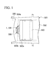
- FIG. 1 is a schematic view of a sunroof drive device 500.
- the sunroof drive device 500 is attached to a roof 502 of a vehicle 501, and drives a roof panel 503 installed on the roof 502.
- the sunroof drive device 500 includes a motor with decelerator 1.
- An opening 502a is formed in the roof 502, and the roof panel 503 is formed to open and close the opening 502a.
- One ends of cables 504a and 504b are connected to the roof panel 503.
- the other ends of the cables 504a and 504b are connected to the motor with decelerator 1, and the roof panel 503 opens and closes the opening 502a when the motor with decelerator 1 is driven.
- the motor with decelerator 1 is disposed between the opening 502a of the roof 502 and a front glass 505.
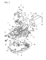
- FIG. 2 is a perspective view of the motor with decelerator 1.
- FIG. 3 is an exploded perspective view of the motor with decelerator 1.
- the motor with decelerator 1 includes an electric motor 2 and a gear casing 3 in which a deceleration mechanism 20 is accommodated and a brush unit 4 is attached to the gear casing 3.
- the deceleration mechanism 20 is constituted by a worm shaft configured to transmit power of the electric motor 2, a worm wheel meshed with the worm shaft (neither of which is shown), and an output shaft 20a connected to the worm wheel.
- the other ends of the cables 504a and 504b are connected to the output shaft 20a.
- the gear casing 3 configured to accommodate the deceleration mechanism 20 is formed of resin, can be divided into an upper case 31 and a lower case 32, and is configured such that the deceleration mechanism 20 can be accommodated in the upper case 31.
- the motor with decelerator 1 is attached to a vehicle interior side of the roof 502 in a state in which the upper case 31 is directed to the roof 502 side and the output shaft 20a is directed to the roof 502 side.
- a circuit board 33 configured to drive the electric motor 2 is accommodated in the lower case 32.
- a female terminal 35a connectable to the brush unit 4 is mounted in the circuit board 33.
- a connector section 34 connectable to an outer connector (not shown) is installed at the lower case 32. The connector section 34 and the circuit board 33 are electrically connected to each other.
- an electric motor accommodating section 36 configured to accommodate a portion of the electric motor 2 is formed at the upper case 31 at a place at which the electric motor 2 is attached.
- An outer flange section 37 configured to attach the electric motor 2 is integrally formed with an outer circumferential portion of the electric motor accommodating section 36.
- the brush unit 4 is attached to the upper case 31 opposite to the electric motor 2 with the outer flange section 37 sandwiched therebetween.
- the electric motor 2 is a so-called brushed motor configured to feed power using a brush 5.
- the electric motor 2 includes a cylindrical yoke housing 6 having an opening 6a and a bottom wall 6b, and an armature 7 rotatably installed in the yoke housing 6.
- the yoke housing 6 is attached to the gear casing 3 in a state in which the opening 6a is directed to the gear casing 3 side.
- Two slits 9 into which nuts 8 can be inserted are formed at areas of the circumferential wall 6b of the yoke housing 6 close to the opening 6a.
- Insertion holes 27 into which bolts 10 can be inserted as a fastening unit are formed at the outer flange section 37 of the gear casing 3 at areas corresponding to the nuts 8 inserted into the slits 9 of the yoke housing 6.
- a permanent magnet 13 is installed at an inner surface of the circumferential wall 6b of the yoke housing 6.
- a bearing 12 configured to rotatably support one end of a rotary shaft 11 of the armature 7 is installed at a bottom wall 6c of the yoke housing 6. The bearing 12 protrudes from the bottom wall 6c toward the outside of the yoke housing 6 in an axial direction of the rotary shaft 11.
- the armature 7 includes the rotary shaft 11, an armature core 14, and a commutator 15.
- the armature core 14 is fitted and fixed to an area of the outer circumferential portion of the rotary shaft 11 corresponding to the permanent magnet 13.
- the commutator 15 is fitted and fixed to an area of the outer circumferential portion of the rotary shaft 11 close to the gear casing 3.
- a winding 16 is wound and mounted on the armature core 14, and a terminal section of the winding 16 is connected to the commutator 15.
- the commutator 15 having a columnar shape is disposed to face an inner wall of the electric motor accommodating section 36 of the gear casing 3.
- a plurality of segments (not shown) having a plate shape are installed in parallel at the outer circumferential surface.
- the terminal section of the winding 16 is connected to these segments.
- a pair of brushes 5 and 5 disposed at both sides with the commutator 15 sandwiched therebetween and constituting the brush unit 4 come in slidable contact with the commutator 15.
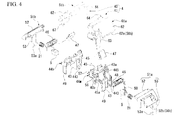
- FIG. 4 is an exploded perspective view of the brush unit 4.
- FIG. 5 is a longitudinal cross-sectional view of a first unit 41 constituting the brush unit 4.
- the brush unit 4 is constituted by two units 41 and 42 including the first unit 41 and a second unit 42, which correspond to the pair of brushes 5 and 5.
- the first unit 41 is installed to be detachable from an upper surface 31 a of the upper case 31 constituting the gear casing 3 (an upper side of FIGS. 3 to 5 , hereinafter, simply referred to as an upper side) opposite to the lower case 32.
- An outer surface side of the first unit 41 is covered by a GN D terminal 61 a. That is, the GND terminal 61a is installed at a side at which the output shaft 20a of the deceleration mechanism 20 is disposed with respect to an upper case 3. Accordingly, the motor with decelerator 1 is disposed in a state in which the GND terminal 61 a and the output shaft 20a are directed to the roof 502 side.
- the first unit 41 has a holder stay 44a with which a brush holder 43 configured to accommodate the brush 5 is integrally formed.
- the second unit 42 also has a holder stay 44b having the same shape. That is, in the embodiment, the holder stays 44a and 44b are divided and disposed to correspond to the brush holders 43 of the first unit 41 and second unit 42, respectively.
- the brush 5 is configured to supply current to the winding 16 via the commutator 15, and has a quadrangular cross-sectional shape.
- One end of a pigtail 50 is connected to the base end side of the brush 5.
- the brush holder 43 is formed of resin.
- the brush holder 43 has a quadrangular cylindrical shape to correspond to the cross-sectional shape of the brush 5, and openings 443 formed at both ends thereof as small openings.
- the brush 5 is accommodated in the brush holder 43 to advance and retreat with respect to the commutator 15. That is, the pair of brush holders 43 have the openings 443 formed at both ends in advancing and retreating directions of the brush 5, and accommodate the pair of brushes 5 to enable advance and retreat with respect to the commutator 15.
- the brush holders 43 are accommodated in the gear casing 3 when the brush unit 4 is attached to the gear casing 3.
- a concave section (an accommodating concave section) 38 configured to allow insertion of the first unit 41 and the second unit 42 from the outside is formed in the gear casing 3.
- An accommodating section 38a configured to accommodate the brush holder 43 is formed at an area of the concave section 38 corresponding to the brush holder 43.
- An opening (not shown) is formed at an area of the accommodating section 38a corresponding to the brush 5.
- a front end of the brush 5 slidably contacts a segment (not shown) of the commutator 15 via the opening.
- FIG. 6 is a perspective view of the holder stay 44a.
- the holder stay 44a which is formed of resin, is integrally formed with an upper surface 43a of the brush holder 43 to be disposed at an outer surface of the gear casing 3. Then, the holder stay 44a is configured to protrude from the brush holder 43 toward the second unit 42 side (a left side of FIG. 4 ) along the concave section 38 of the upper case 31.
- a box-shaped device accommodating section 45 having an opening 445 formed at the outside as a large opening is formed at an area thereof protruding toward the second unit 42 side.
- the device accommodating section 45 is configured by integrally forming an accommodating section main body 40a configured to accommodate a choke coil 46 and a condenser 47 as a noise prevention device and a pigtail accommodating section 40b configured to accommodate the pigtail 50 of the brush 5 with each other.
- the accommodating section main body 40a is in communication with the pigtail accommodating section 40b.
- a male terminal 49 is installed at a bottom wall 45a of the accommodating section main body 40a in the vicinity of the pigtail accommodating section 40b.
- the male terminal 49 is configured to extend from the bottom wall 45a in an attachment/detachment direction (a vertical direction of FIGS. 4 and 5 ) of the first unit 41.
- the male terminal 49 is connected to the female terminal 35a of the circuit board 33 accommodated in the lower case 32 in a state in which the first unit 41 is attached to the upper case 31.
- the choke coil 46 is accommodated in the device accommodating section 45 at a position closer to the second unit 42.
- the other end of the pigtail 50 is connected to one end of the choke coil 46.
- the choke coil 46 is wound about an axle 48.
- a winding direction of the choke coil 46 is set to a left rotation direction (see an arrow Y1 of FIG. 6 ) from one end side of the choke coil 46, that is, one end side of the axle 48 (an end portion close to the pigtail accommodating section 40b in FIG. 6 ) toward the other end side (an end portion far from the pigtail accommodating section 40b in FIG. 6 ).
- the other end of the choke coil 46 is connected to the male terminal 49. Accordingly, current is supplied to the brush 5 via the female terminal 35a of the circuit board 33, the male terminal 49 of the first unit 41, the choke coil 46, and the pigtail 50.
- one end of the condenser 47 is connected to the male terminal 49.
- the condenser 47 is accommodated in the device accommodating section 45 opposite to the second unit 42 (a right side of FIGS. 4 and 6 ), that is, the outside of the choke coil 46. Further, the other end of the condenser 47 is connected to the GND terminal 61a. Accordingly, the choke coil 46 is serially connected to a power feeding line between the brush 5 and the male terminal 49. Meanwhile, the condenser 47 is installed in parallel with the choke coil 46. As a result, a cover 51 a configured to close the outside of the holder stay 44a is attached to the holder stay 44a in which the choke coil 46 and the condenser 47 are accommodated.
- the cover 51a is constituted by a cover main body 52 and a spring stopper 53, which are integrally formed with each other.
- the cover main body 52 closes the opening of the accommodating section main body 40a of the holder stay 44a and the opening 445 of the device accommodating section 45, which is a portion of the opening of the pigtail accommodating section 40b.
- the spring stopper 53 closes a portion of the opening of the pigtail accommodating section 40b and the opening 443 of the base end side of the brush holder 43.
- a claw section 53a bent and extending to turn toward a lower surface 43b of the brush holder 43 is formed at a front end of the spring stopper 53.
- the cover 51a is attached to the holder stay 44a.
- the spring stopper 53 is accommodated in the accommodating section 38a formed in the concave section 38 of the gear casing 3 with portions of the brush holder 43 and the holder stay 44a.
- a coil spring 21 configured to bias the brush 5 toward the commutator 15 is accommodated in the brush holder 43.
- the cover 51a is attached to the brush holder 43, one end of the coil spring 21 is supported by the spring stopper 53 of the cover 51 a. Accordingly, the other end of the coil spring 21 securely biases the brush 5 toward the commutator 15.
- a hook section 54 having an L-shaped cross section is formed at a side edge 52a of the electric motor 2 side (a left side in FIG 5 ) of the cover main body 52 to extend toward the electric motor 2.
- the hook section 54 is formed to surround a circumferential edge of the outer flange section 37 of the gear casing 3.
- a convex section 55 disposed to face the inside of the hook section 54 is formed at the circumferential edge of the outer flange section 37.
- the convex section 55 is continuously formed along the circumferential edge of the outer flange section 37.
- the convex section 55 of the embodiment has an arc shape along the circumferential edge of the arc-shaped outer flange section 37.
- a side edge 52b of the spring stopper 53 side of the cover main body 52 is formed to protrude toward the outside of the gear casing 3 more than the circumferential edge of the concave section 38, that is, toward an opposite side of the second unit 42.
- the labyrinth sections 56a and 56b are formed in the gap between the cover main body 52 and the gear casing 3 by the side edge 52b of the cover main body 52, the circumferential edge of the concave section 38 of the gear casing 3, and the GND terminal 61a.
- the circumferential edge of the cover main body 52 is disposed between the concave section 38 and the circumferential edge of the holder stay 44a. That is, the labyrinth sections 56a and 56b are formed between the circumferential edge of the concave section 38 and the circumferential edge of the holder stay 44a corresponding to the circumferential edge of the concave section 38.
- a cutout portion 58 is formed in a sidewall 57 of the cover main body 52 at an opposite side (a left side in FIG. 5 ) of the outer flange section 37 of the gear casing 3.
- the cutout portion 58 integrates with the holder stay 44a and the GND terminal 61a as the cutout portion 58 is engaged with a convex section 65 (to be described later) formed in the GND terminal 61a.
- the GND terminal 61 a is formed by performing press processing on a metal plate formed of, for example, brass, or the like.
- the GND terminal 61 a is configured by integrally forming a terminal main body 62 configured to cover the cover main body 52 of the cover 51a from the outside thereof and a GND terminal 63 extending from the circumferential edge of the terminal main body 62 to the lower case 32 side (a lower side of FIGS. 3 to 5 , hereinafter, simply referred to as a lower side).
- a Y terminal section 64 is integrally formed with the terminal main body 62 adjacent to the outer flange section 37 of the gear casing 3 at an area corresponding to the insertion hole 27. That is, the respective GND terminals 61a and 61 b of the two units 41 and 42 have the Y terminal sections 64, which are disposed to oppose each other.
- the Y terminal sections 64 are fastened by the bolt 10 and the nut 8 with the outer flange section 37 of the gear casing 3 and the yoke housing 6 of the electric motor 2. Accordingly, the GND terminal 61 a is fastened and fixed to the gear casing 3, and movement in a removal direction of the holder stay 44a is restricted by the GND terminal 61a.
- the Y terminal section 64 is electrically connected to the Y terminal section 64 formed at a GND terminal 61b of the second unit 42 and the yoke housing 6 via the bolt 10 configured to fasten and fix the gear casing 3 and the yoke housing 6. That is, the GND terminals 61a and 61b are divided such that the GND terminals, which were an integrated member in the related art, correspond to the pair of brushes 5 and 5.
- a gap S as shown in FIG 2 is formed between the Y terminal sections 64 and 64.
- the convex section 65 is formed in a sidewall 66 overlapping the sidewall 57 of the holder stay 44a to protrude toward the sidewall 57 of the holder stay 44a.
- the convex section 65 is disposed at a position corresponding to the cutout portion 58 formed in the holder stay 44a, and engaged with the cutout portion 58. Accordingly, the holder stay 44a, the cover 51 a, and the GND terminal 61a are integrated with each other.
- a side edge 62a of the terminal main body 62 opposite to the second unit 42 is formed to extend from the side edge 52b toward the lower side to cover the side edge 52b of the cover main body 52.
- the extended portion constitutes a portion of a labyrinth section 56b.
- the GND terminal of the GND terminal 61a extends to arrive at the circuit board 33 passing through the upper case 31 and accommodated in the lower case 32.
- a female terminal 35b connectable to the GND terminal 63 is mounted in the circuit board 33. As the GND terminal 63 is connected to the female terminal 35b, the GND terminals 61a and 61b are grounded to the GND.
- the male terminal 49 is installed in a standing state in the vicinity of the pigtail accommodating section 40b in the bottom wall 45a of the accommodating section main body 40a.
- the male terminal 49 is installed in a standing state at the bottom wall 45a of the accommodating section main body 40a opposite to the pigtail accommodating section 40b.
- the GND terminal 63 is installed at the GND terminal 61a of the first unit 41, the GND terminal 63 is not installed at the GND terminal 61 b of the second unit 42. This is because the GND terminal 61 a of the first unit 41 and the GND terminal 61b of the second unit 42 are electrically connected to each other via the bolt 10.
- a tongue-shaped section 67 is bent downward at the GND terminal 61b of the second unit 42 opposite to the Y terminal section 64 of the terminal main body 62. Meanwhile, a slit 29 is formed in an area of the upper case 31 of the gear casing 3 corresponding to the tongue-shaped section 67. As the tongue-shaped section 67 enters the slit 29, looseness of the GND terminal 61b of the second unit 42 is prevented.
- the first unit 41 and the second unit 42 constituting the brush unit 4 are assembled to the gear casing 3 through the same assembly method. For this reason, in the following description, the assembly method of the first unit 41 will be described, and the assembly method of the second unit 42 will be omitted.
- the male terminal 49 is assembled to the holder stay 44a.
- the other end of the pigtail 50 is connected to one end of the choke coil 46 through spot welding or the like. After that, the choke coil 46 is accommodated in the device accommodating section 45, and the brush 5 is accommodated in the brush holder 43.
- the condenser 47 is accommodated in the device accommodating section 45.
- the coil spring 21 is accommodated from the base end side (a rear side in a direction in which the brush 5 is biased) of the brush 5 of the brush holder 43.
- the cover 51a is attached to the holder stay 44a.
- the other end of the choke coil 46 and one end of the condenser 47 are connected to the male terminal 49 through soldering or the like.
- the GND terminal 61a is attached from above the cover 51a.
- the convex section 65 of the GND terminal 61a is engaged with the cutout portion 58 of the holder stay 44a. Accordingly, the GND terminal 61a is prevented from being easily dropped from the holder stay 44a.
- the other end of the condenser 47 is connected to the GND terminal 61 a through spot welding or the like. Accordingly, assembly of the first unit 41 is completed.
- the first unit 41 and the second unit 42 are attached to the concave section 38 of the gear casing 3.
- the brush holders 43 and 43 of the units 41 and 42 are directed toward the concave section 38 to assemble the units 41 and 42 from above the upper case 31.
- a front end of the brush 5 is pressed using a jig (not shown) such that a front end of the brush 5 accommodated in the brush holder 43 does not protrude.
- the jig is removed while the brush holders 43 and 43 are inserted into the accommodating section 38a of the concave section 38.
- the first unit 41 and the second unit 42 can be separately assembled to the gear casing 3. For this reason, the units 41 and 42 can be smoothly assembled regardless of manufacturing precision of the gear casing 3.
- the first unit 41 and the second unit 42 are separately assembled to the gear casing 3.
- the gap S is formed between the Y terminal sections 64 and 64 as shown in FIG 2 .
- the labyrinth sections 56a and 56b are formed at a gap between the circumferential edge of the concave section 38 formed at the upper case 31 of the gear casing 3 and the circumferential edge of the cover main body 52 of the units 41 and 42. That is, the labyrinth sections 56a and 56b are installed between the circumferential edge of the concave section 38 and the circumferential edge of the holder stay 44a corresponding to the circumferential edge of the concave section 38. For this reason, infiltration of dust into the gear casing 3 can be prevented without maintaining high precision of a dimensional relation between the upper case 31 and the units 41 and 42.
- a surge voltage is generated by self induction when the brush 5 in a power-on state covers the segment (not shown) of the commutator 15. Electromagnetic noise is radiated from the sliding contact section between the brush 5 and the commutator 15 by the surge voltage.
- the GN D terminals 61 a and 61b are installed at the first unit 41 and the second unit 42 constituting the brush unit 4, influence of the electromagnetic noise can be suppressed.
- an antenna may be installed on the roof 502, to which the motor with decelerator 1 is attached, as an information transmission reception unit of a communication instrument, for example, a car navigation system or the like.
- the electromagnetic noise due to the motor with decelerator 1 may exert an influence on the communication instrument.
- the motor with decelerator 1 is disposed in a state in which the GND terminals 61 a and 61 b are directed toward the roof 502. That is, the GND terminals 61a and 61b are disposed between the information transmission reception unit of communication instrument and the brush 5. Accordingly, influence of the electromagnetic noise on the antenna can be prevented.
- the choke coil 46 is wound leftward when the choke coil 46 is wound from one end side close to the pigtail accommodating section 40b of the axle 48 toward the other end side separated from the pigtail accommodating section 40b.
- the condenser 47 is accommodated in the device accommodating section 45 at an opposite side (a right side of FIGS. 4 and 6 ) of the second unit 42, that is, the outside of the choke coil 46. For this reason, an electromagnetic noise at a specified frequency range is reduced.
- FIGS. 7A and 7B are graphs of electromagnetic noise upon driving of a motor, with a vertical axis representing a strength in "dB ⁇ V" of the electromagnetic noise and a horizontal axis representing a frequency in "Hz.”
- FIG. 7A shows a case in which the choke coil 46 is wound as in the first embodiment.
- FIG. 7B shows a case in which the choke coil 46 is wound in a direction opposite to that of FIG 7A .
- the electromagnetic noise at the radio frequency range is reduced (see a portion A of FIG. 7A ).
- the electromagnetic noise at the intermediate frequency range is slightly increased (see a portion B of FIG. 7A ).
- the brush holders 43 are integrally formed with the holder stays 44a and 44b corresponding to the brush holders 43. Accordingly, according to the above-mentioned first embodiment, in comparison with the case in which only the brush holder 43 is assembled with respect to the gear casing 3 as in the related art, assembly workability of the brush holders 43 can be improved. That is, as functions of the holder stays 44a and 44b are provided to the brush holder 43 side rather than the gear casing 3 side, parts configured to assemble the brush 5 can be increased in size without increasing the entire size of the motor with decelerator 1. In addition, the holder stays 44a and 44b are separately formed such that the holder stays 44a and 44b correspond to the pair of brushes 5. For this reason, assembly workability of the brush holders 43 can be improved.
- the holder stays 44a and 44b are integrated with the brush holders 43 to increase the size of the parts in comparison with a single body brush holder 43, dimension management of the parts becomes easy, and assembly workability of the brush holder 43 can be improved.
- the labyrinth sections 56a and 56b are formed in a gap between the circumferential edge of the concave section 38 formed at the upper case 31 of the gear casing 3 and the circumferential edge of the cover main body 52 of the units 41 and 42. That is, the labyrinth section 56a is installed between the circumferential edge of the concave section 38 and the circumferential edge of the holder stay 44a corresponding to the circumferential edge of the concave section 38.
- the looseness can be maintained between the upper case 31 and the units 41 and 42. That is, processing precision of the concave section 38 of the upper case 31 and the cover main body 52 of the units 41 and 42 can be relaxed, manufacturing cost can be reduced, and infiltration of dust into the gear casing 3 can be prevented.
- the brush 5, the brush holder 43, the holder stays 44a and 44b, and the electromagnetic shields 61a and 61b are assembled to the gear casing 3 and integrated with each of the pair of brushes 5. For this reason, the brush 5, the brush holder 43, the holder stays 44a and 44b, and the electromagnetic shields 61 a and 61 b can be collectively assembled, and the assembly workability can be further improved.
- the GND terminals 61 a and 61b are electrically connected to the yoke housing 6 via the bolt 10 configured to fasten and fix the gear casing 3 and the yoke housing 6 in a state in which the Y terminal sections 64 are disposed to oppose each other. For this reason, when the yoke housing 6 is attached to the gear casing 3, the GND terminals 61a and 61b can be simultaneously attached to the gear casing 3, an assembly task can be easily performed, and the electromagnetic noise generated from the electric motor 2 can be suppressed.
- the sunroof drive device 500 having high reliability can be provided.
- FIG. 8 is a perspective view of a motor with decelerator 100 according to the second embodiment.
- FIG. 9 is an exploded perspective view of a brush unit 104 according to the second embodiment.
- a basic configuration of the motor with decelerator 100 is the same as the above-mentioned first embodiment as follows.
- the motor with decelerator 100 is attached to the roof 502 of the vehicle 501 using the sunroof drive device 500.
- the motor with decelerator 100 includes the electric motor 2, and the gear casing 3 in which the deceleration mechanism 20 is accommodated, and the brush unit 104 is attached to the upper case 31 of the gear casing 3.
- the electric motor 2 is a so-called brushed motor configured to supply power using the brush 5.
- a difference between the second embodiment and the first embodiment is as follows. While the choke coil 46 and the condenser 47 are installed at the brush unit 4 of the first embodiment, the choke coil 46 and the condenser 47 are not installed at the brush unit 104 of the second embodiment.
- the brush unit 104 is constituted by two units 141 and 142, that is, a first unit 141 and a second unit 142, which correspond to the pair of brushes 5 and 5.
- basic configurations of the two units 141 and 142 are the same, and the respective components are formed substantially symmetrically with respect to the commutator 15.
- first unit 141 will be described in detail.
- second unit 142 parts having different shapes from the first unit 141 will be described, common configurations to the first unit 141 are designated by the same reference numerals as those of the first unit 141 and description thereof will be omitted.
- the first unit 141 is detachably installed at the upper surface 31a of the upper case 31 constituting the gear casing 3, and an outer surface side thereof is covered by a GND terminal 161a. That is, the motor with decelerator 100 is disposed in a state in which the GND terminals 161 a and 161b are directed toward the roof 502. Accordingly, the GND terminals 161 a and 161 b are disposed between the roof 502 and the brush 5.
- the first unit 141 has a holder stay 144a with which a brush holder 143 is integrally formed to accommodate the brush 5.
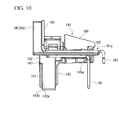
- FIG. 10 is a side view of the first unit 141.
- FIG. 11 is a front view of the first unit 141.
- the holder stay 144a of the first unit 141 is formed of resin.
- the holder stay 144a is integrally formed with an upper portion of the brush holder 143 to be disposed on an outer surface of the gear casing 3.
- the holder stay 144a has a base section 145a formed along the concave section 38 of the upper case 31.
- a front wall 146 standing up to correspond to the outer flange section 37 of the gear casing 3 is integrally formed at the electric motor 2 side (a left side of FIG. 10 ) of the base section 145a.
- the hook section 54 having an L-shaped cross-section is formed at the circumferential edge of the front wall 146 to extend toward the electric motor 2.
- the hook section 54 is formed to surround the circumferential edge of the outer flange section 37 of the gear casing 3.
- the labyrinth section 56a is formed at a gap between the holder stay 144a and the gear casing 3 by the hook section 54 and the convex section 55 formed in the outer flange section 37.
- a side edge 145c of the base section 145a opposite to the second unit 142 is formed to protrude toward the outside more than the circumferential edge of the concave section 38 of the gear casing 3.
- the labyrinth section 56b is formed at the gap between the holder stay 144a and the gear casing 3 by the side edge 145c of the base section 145a, the circumferential edge of the concave section 38 of the gear casing 3, and the GND terminal 161 a (to be described later).
- an engaging section 130 configured to attach the GND terminal 161a is integrally formed with an upper surface of the base section 145a.
- a spring stopper 151 configured to close an opening 143a of a base end side (a front side of FIG. 10 ) of the brush 5 is formed at the brush holder 143.
- the spring stopper 151 is formed of a resin plate member and has a rectangular shape to correspond to the opening 143a of the brush holder 143 when seen in a plan view.
- a claw section 153 bent and extending to surround a lower surface 143b of the brush holder 143 is formed at a lower end of the spring stopper 151.
- a tongue-shaped section 152 extending toward the electric motor 2 of FIG. 8 is formed at an upper end of the spring stopper 151.
- a cutout portion 147 configured to receive the tongue-shaped section 152 is formed at an area of the brush holder 143 corresponding to the tongue-shaped section 152. As the cutout portion 147 is engaged with the tongue-shaped section 152 and the claw section 153 is engaged with the lower surface 143b of the brush holder 143, the spring stopper 151 is attached to the opening 143a of the brush holder 143.
- the cutout portion 147 formed in the brush holder 143 is opened at the outside thereof with respect to the commutator 15.
- the base section 145a is slightly cut such that the upper end of the cutout portion 147 is disposed above the upper end of the opening.
- a length L1 in a longitudinal direction of the cutout portion 147 is set to be greater than a length L2 in a longitudinal direction of the tongue-shaped section 152 of the spring stopper 151. Accordingly, the tongue-shaped section 152 can be slightly slidably moved toward the base section 145a in the longitudinal direction of the brush holder 143.
- the coil spring 21 configured to bias the brush 5 toward the commutator 15 is accommodated in the brush holder 143. As the spring stopper 151 is attached to the brush holder 143, the coil spring 21 securely biases the brush 5 toward the commutator 15.
- the GND terminal 161 a is formed by perfomring press processing or the like on a metal plate formed of, for example, brass or the like.
- the GND terminal 161a has a terminal base 162 configured to cover the base section 145a of the spring stopper 151.
- a front wall shield section 163 configured to cover one surface of the front wall 146 integrally formed with the holder stay 144a is bent and formed at the terminal base 162.
- the Y terminal section 64 is integrally formed with the front wall shield section 163. Even in the Y terminal section 64 of the second embodiment, similar to the first embodiment, a gap S is formed between the Y terminal sections 64 and 64 as shown in FIG. 8 in a state in which the units 141 and 142 are attached to the gear casing 3.
- a side edge 162a of the terminal base 162 opposite to the second unit 142 extends toward the outside more than the base section 145a of the spring stopper 151.
- the extended portion constitutes a portion of the labyrinth section 56b.
- an auxiliary shield section 164 extending to bend toward the second unit 142 is integrally formed with the terminal base 162 opposite to the front wall shield section 163.
- a claw section 168 engageable with the engaging section 130 is formed between the front wall shield section 163 and the auxiliary shield section 164 and at an area thereof corresponding to the engaging section 130 of the holder stay 144a.
- a hole 130a into which the claw section 168 of the GN D terminal 161a can be inserted is formed in the engaging section 130 of the holder stay 144a.
- a GND terminal 63 extends to be bent downward at a GND terminal 161b of the second unit 142 opposite to the front wall shield section 163 of the terminal base 162b. Accordingly, when the two GND terminals 161a and 161b are fastened and fixed to the gear casing 3 by the bolt 10, both of the GND terminals 161 a and 161 b are electrically connected, and influence of the electromagnetic noise can be suppressed.
- a tongue-shaped section 167 is formed to bend downward at the GND terminal 161 a of the first unit 141 opposite to the front wall shield section 163 of the terminal base 162.
- a slit 129 is formed at an area of the upper case 31 of the gear casing 3 corresponding to the tongue-shaped section 167, and the tongue-shaped section 167 is inserted thereinto. Accordingly, the looseness of the GND terminal 161 a of the first unit 141 is prevented.
- FIG. 11 is a view for explaining the assembly method of the brush unit 104.
- Both assembly methods of the first unit 141 and the second unit 142 constituting the brush unit 104 are the same. Accordingly, in the following description, only the assembly method of the first unit 141 will be described, and description of the assembly method of the second unit 142 will be omitted.
- the male terminal 49 is attached to the holder stay 144a, the brush 5 is accommodated in the brush holder 143, and the pigtail 50 of the brush 5 (not shown in the second embodiment) is connected to the male terminal 49 through soldering or the like.
- the coil spring 21 (not shown in the second embodiment) is accommodated from the base end side (a right side of FIG. 11 ) of the brush 5 of the brush holder 143 to attach the spring stopper 151.
- the GND terminal 161 a is attached to the holder stay 144a.
- the first unit 141 and the second unit 142 are attached to the concave section 38 of the gear casing 3.
- the brush holders 143 and 143 of the units 141 and 142 are directed toward the concave section 38, and the units 141 and 142 are assembled from above the upper case 31 (see an arrow Y2 of FIG. 11 ).
- a front end of the brush 5 is pushed to assemble the units 141 and 142 using a jig (not shown) such that the front end of the brush 5 accommodated in the brush holder 43 does not protrude.
- the jig is removed while inserting the brush holders 143 and 143 into the accommodating section 38a of the concave section 38.
- the claw section 153 of the spring stopper 151 may collide with a circumferential wall 3a of the gear casing 3.
- an upward force is applied to the claw section 153 as shown by an arrow Y3 of FIG. 11 .
- an upward force is applied to the tongue-shaped section 152 as shown by an arrow Y4 of FIG. 11 .
- a length L1 in a longitudinal direction of the cutout portion 147 formed in the brush holder 143 is set to be greater than a length L2 in a longitudinal direction of the tongue-shaped section 152 of the spring stopper 151.
- the tongue-shaped section 152 when an upward force is applied to the tongue-shaped section 152, the tongue-shaped section 152 slightly slidably moves toward the base section 145a in the longitudinal direction of the brush holder 143. For this reason, the spring stopper 151 can be prevented from being dropped from the brush holder 143.
- the GND terminals 161a and 161b are fastened and fixed to the gear casing 3 by the bolt 10. Accordingly, assembly of the first unit 141 and the second unit 142 is completed.
- the same effects as in the above-mentioned first embodiment can be obtained.
- variation of the motor with decelerator can be increased. For this reason, the motor with decelerator can be appropriately provided according to a demand of a user.
- the present invention is not limited to the embodiments. Additions, omissions, substitutions and the other modifications of components are possible without departing from the scope of the spirit of the present invention.
- the present invention is not limited to the above description but limited only by the accompanying claims.
- the motor with decelerator 1 or 100 includes the electric motor 2 and the gear casing 3 in which the deceleration mechanism 20 is accommodated, and the brush unit 4 or 104 is attached to the upper case 31 of the gear casing 3 has been described.
- the present invention is not limited thereto, and the brush unit 4 or 104 may be attached to the electric motor 2 only.
- assembly workability of the brush holder can be improved and assembly precision of the brush holder can be increased.
Landscapes
- Engineering & Computer Science (AREA)
- Power Engineering (AREA)
- Physics & Mathematics (AREA)
- Electromagnetism (AREA)
- Motor Or Generator Frames (AREA)
- Connection Of Motors, Electrical Generators, Mechanical Devices, And The Like (AREA)
Abstract
Description
- The present invention relates to an electric motor, a motor with decelerator, and a sunroof drive device using the same.
This application claims priority to and the benefit of Japanese Patent Application No.2010-102140 filed on April 27, 2010 - In the related art, a motor with decelerator in which an electric motor and a gear casing configured to accommodate a deceleration connected to a rotary shaft of the electric motor are integrated with each other is well known. Such an electric motor is, for example, a brushed motor including an armature and a pair of brushes configured to slidably contact a commutator of the armature.
The pair of brushes are attached to the gear casing and accommodated in brush holders thereof. The brush holders are formed of resin, and two brush holders are installed to correspond to the brushes. The pair of brush holders are configured to be detachable with respect to the gear casing (for example, see Patent Document 1). -
- [Patent Document 1] Japanese Patent Application, First Publication No.
2006-211857 - However, in the above-mentioned related art, since only small parts such as brush holders are mounted on the gear casing, the brush holders cannot be easily assembled, and assembly precision of the brush holders cannot be easily increased.
- Here, in consideration of the above-mentioned problems, the present invention provides an electric motor, a motor with decelerator, and a sunroof drive device capable of improving assembly workability of a brush holder and increasing assembly precision of the brush holder.
- In order to solve the problems, an electric motor according to a first aspect of the present invention includes an armature; a pair of brushes disposed at both sides with a commutator, which is installed in the armature, sandwiched therebetween and in sliding contact with the commutator to feed power; a pair of brush holders configured to accommodate the pair of brushes to advance and retreat with respect to the commutator; and holder stays configured to support the brush holders. The brush holders and the holder stays are integrally formed with each other by resin, and the holder stays are divided and disposed to correspond to the brush holders.
- As described above, since the holder stays are integrated with the brush holders, like the related art, in comparison with the case in which only the brush holder is assembled with respect to the gear casing, assembly workability of the brush holder can be improved.
That is, parts configured to assemble the brush can be increased in size without increasing the size of the entire motor. In addition, the holder stays are separately configured to correspond to the brush holders.
For this reason, assembly workability of the brush holder can be improved.
In addition, as the parts are increased in size, dimension management of the parts becomes easy, and assembly precision of the brush holder can be increased. - A motor with decelerator according to a second aspect of the present invention includes the electric motor, a gear casing integrally attached to the electric motor; and a deceleration mechanism accommodated in the gear casing and connected to a rotary shaft of the electric motor. In addition, an accommodating concave section configured to accommodate the holder stay and the brush holder is formed at the gear casing, and the holder stay and the brush holder are attached to the accommodating concave section. Further, a labyrinth section is formed between a circumferential edge of the accommodating concave section and an area of the holder stay corresponding to the circumferential edge.
- According to the above-mentioned configuration, even when processing precision of the accommodating concave section, the holder stay, and the brush holder is relaxed, infiltration of dust into a gap between the accommodating concave section and the holder stay and a gap between the accommodating concave section and the brush holder can be prevented. For this reason, manufacturing cost can be reduced, and the influence dust infiltration can be suppressed.
- In the motor with decelerator, electromagnetic shields configured to suppress the influence of electromagnetic noise may be installed at the outsides of the holder stays, respectively.
- A surge voltage is generated by self induction when the brush steps over an adjacent segment of the commutator in a power-on state, and the electromagnetic noise is radiated from an area at which the brush and the commutator are in sliding contact with each other by the surge voltage. For this reason, for example, when the motor with decelerator is mounted on a vehicle, the influence of the electromagnetic noise may be applied to the other electrical components or the like.
However, as the electromagnetic shield is installed at the outside of the holder stay, the influence of the electromagnetic noise can be suppressed. - In the motor with decelerator, in a state in which the electromagnetic shields are attached to the holder stays and the holder stay, the brush holder, and the electromagnetic shield are integrated, the holder stay, the brush holder, and the electromagnetic shield may be attached to the gear casing.
- According to the above-mentioned configuration, the brush, the brush holder, the holder stay, and the electromagnetic shield can be integrated and assembled to the gear casing. For this reason, assembly workability can be further improved.
- In the motor with decelerator, the electromagnetic shield may be divided to correspond to the holder stays, and the electromagnetic shields may be attached to the gear casing by a fastening unit configured to attach the electric motor and the gear casing.
- According to the above-mentioned configuration, when the electric motor and the gear casing are attached, the electromagnetic shield can be simultaneously attached to the gear casing, and an assembly task becomes easy. Further, since the electromagnetic shield and a yoke housing of the electric motor are electrically connected via a fastening unit, the electromagnetic noise generated from the electric motor can be suppressed.
- A sunroof drive device according to a third aspect of the present invention is a sunroof drive device in which the motor with decelerator is installed on a roof of a vehicle, and a roof panel installed on the roof is driven using the motor with decelerator. In this state, the motor with decelerator is disposed in a state in which the electromagnetic shield is directed toward the roof.
- According to the above-mentioned configuration, the influence of the electromagnetic noise on an antenna or the like installed on the roof of the vehicle can be prevented. For this reason, the sunroof drive device having high reliability can be provided.
- According to the present invention, since the brush holders are integrated with the holder stays, assembly workability of the brush holders can be improved in comparison with the case in which only the brush holders are assembled with respect to the gear casing.
That is, components assembled to the gear casing can be increased in size without an increase in size of the motor as a whole. In addition to this, the holder stays are separately configured to correspond to the brush holders.
For this reason, assembly workability of the brush holders can be improved.
In addition, as the components are increased in size, dimension management of the components becomes easy, and assembly precision of the brush holders can be increased. -
-
FIG. 1 is a schematic configuration view of a sunroof drive device according to a first embodiment of the present invention. -
FIG. 2 is a perspective view of a motor with decelerator according to the first embodiment of the present invention. -
FIG. 3 is an exploded perspective view of the motor with decelerator according to the first embodiment of the present invention. -
FIG. 4 is an exploded perspective view of a brush unit of the first embodiment of the present invention. -
FIG. 5 is a longitudinal cross-sectional view of a first unit constituting the brush unit of the first embodiment of the present invention. -
FIG. 6 is a perspective view of a holder stay according to the first embodiment of the present invention. -
FIG. 7A is a graph of variation in electromagnetic noise in the first embodiment of the present invention, showing the case in which a choke coil is wound left-handed. -
FIG. 7B is a graph of variation in electromagnetic noise in the first embodiment of the present invention, showing the case in which a choke coil is wound in a direction opposite to that ofFIG. 7A . -
FIG. 8 is a perspective view of a motor with decelerator according to a second embodiment of the present invention. -
FIG. 9 is an exploded perspective view of a brush unit of the second embodiment of the present invention. -
FIG. 10 is a side view of a first unit of the second embodiment of the present invention. -
FIG. 11 is a front view of the first unit of the second embodiment of the present invention. - Next, a first embodiment of the present invention will be described with reference to
FIGS. 1 to 7 .
FIG. 1 is a schematic view of asunroof drive device 500.
As shown inFIG. 1 , thesunroof drive device 500 is attached to aroof 502 of avehicle 501, and drives aroof panel 503 installed on theroof 502. Thesunroof drive device 500 includes a motor with decelerator 1. Anopening 502a is formed in theroof 502, and theroof panel 503 is formed to open and close theopening 502a. One ends ofcables roof panel 503. The other ends of thecables roof panel 503 opens and closes theopening 502a when the motor with decelerator 1 is driven. The motor with decelerator 1 is disposed between theopening 502a of theroof 502 and afront glass 505. -
FIG. 2 is a perspective view of the motor with decelerator 1.FIG. 3 is an exploded perspective view of the motor with decelerator 1.
As shown inFIGS. 2 and3 , the motor with decelerator 1 includes anelectric motor 2 and agear casing 3 in which adeceleration mechanism 20 is accommodated and abrush unit 4 is attached to thegear casing 3.
Thedeceleration mechanism 20 is constituted by a worm shaft configured to transmit power of theelectric motor 2, a worm wheel meshed with the worm shaft (neither of which is shown), and anoutput shaft 20a connected to the worm wheel. The other ends of thecables output shaft 20a. - The
gear casing 3 configured to accommodate thedeceleration mechanism 20 is formed of resin, can be divided into anupper case 31 and alower case 32, and is configured such that thedeceleration mechanism 20 can be accommodated in theupper case 31. The motor with decelerator 1 is attached to a vehicle interior side of theroof 502 in a state in which theupper case 31 is directed to theroof 502 side and theoutput shaft 20a is directed to theroof 502 side.
Acircuit board 33 configured to drive theelectric motor 2 is accommodated in thelower case 32. Afemale terminal 35a connectable to thebrush unit 4 is mounted in thecircuit board 33.
Aconnector section 34 connectable to an outer connector (not shown) is installed at thelower case 32. Theconnector section 34 and thecircuit board 33 are electrically connected to each other. - Here, an electric
motor accommodating section 36 configured to accommodate a portion of theelectric motor 2 is formed at theupper case 31 at a place at which theelectric motor 2 is attached. Anouter flange section 37 configured to attach theelectric motor 2 is integrally formed with an outer circumferential portion of the electricmotor accommodating section 36. Thebrush unit 4 is attached to theupper case 31 opposite to theelectric motor 2 with theouter flange section 37 sandwiched therebetween. - The
electric motor 2 is a so-called brushed motor configured to feed power using abrush 5. Theelectric motor 2 includes acylindrical yoke housing 6 having anopening 6a and abottom wall 6b, and anarmature 7 rotatably installed in theyoke housing 6.
Theyoke housing 6 is attached to thegear casing 3 in a state in which theopening 6a is directed to thegear casing 3 side. Twoslits 9 into whichnuts 8 can be inserted are formed at areas of thecircumferential wall 6b of theyoke housing 6 close to theopening 6a. - Insertion holes 27 into which
bolts 10 can be inserted as a fastening unit are formed at theouter flange section 37 of thegear casing 3 at areas corresponding to thenuts 8 inserted into theslits 9 of theyoke housing 6. As thebolts 10 are inserted into the insertion holes 27 and thebolts 10 are threaded into thenuts 8, theyoke housing 6 is fastened and fixed to thegear casing 3.
In addition, apermanent magnet 13 is installed at an inner surface of thecircumferential wall 6b of theyoke housing 6.
Further, a bearing 12 configured to rotatably support one end of a rotary shaft 11 of thearmature 7 is installed at abottom wall 6c of theyoke housing 6. The bearing 12 protrudes from thebottom wall 6c toward the outside of theyoke housing 6 in an axial direction of the rotary shaft 11. - The
armature 7 includes the rotary shaft 11, anarmature core 14, and acommutator 15. Thearmature core 14 is fitted and fixed to an area of the outer circumferential portion of the rotary shaft 11 corresponding to thepermanent magnet 13. Thecommutator 15 is fitted and fixed to an area of the outer circumferential portion of the rotary shaft 11 close to thegear casing 3. A winding 16 is wound and mounted on thearmature core 14, and a terminal section of the winding 16 is connected to thecommutator 15. - The
commutator 15 having a columnar shape is disposed to face an inner wall of the electricmotor accommodating section 36 of thegear casing 3. In thecommutator 15, a plurality of segments (not shown) having a plate shape are installed in parallel at the outer circumferential surface. The terminal section of the winding 16 is connected to these segments. In addition, a pair ofbrushes commutator 15 sandwiched therebetween and constituting thebrush unit 4 come in slidable contact with thecommutator 15. -
FIG. 4 is an exploded perspective view of thebrush unit 4.FIG. 5 is a longitudinal cross-sectional view of afirst unit 41 constituting thebrush unit 4.
As shown inFIGS. 3 to 5 , thebrush unit 4 is constituted by twounits first unit 41 and asecond unit 42, which correspond to the pair ofbrushes - Here, specific configurations of the two
units commutator 15. For this reason, in the following description, only thefirst unit 41 will be described in detail. For thesecond unit 42, only areas having different shapes from thefirst unit 41 will be described, common elements to thefirst unit 41 are designated by the same reference numerals as those of thefirst unit 41, and description thereof will be omitted. - The
first unit 41 is installed to be detachable from anupper surface 31 a of theupper case 31 constituting the gear casing 3 (an upper side ofFIGS. 3 to 5 , hereinafter, simply referred to as an upper side) opposite to thelower case 32. An outer surface side of thefirst unit 41 is covered by a GN D terminal 61 a. That is, theGND terminal 61a is installed at a side at which theoutput shaft 20a of thedeceleration mechanism 20 is disposed with respect to anupper case 3. Accordingly, the motor with decelerator 1 is disposed in a state in which theGND terminal 61 a and theoutput shaft 20a are directed to theroof 502 side.
Thefirst unit 41 has aholder stay 44a with which abrush holder 43 configured to accommodate thebrush 5 is integrally formed. Thesecond unit 42 also has aholder stay 44b having the same shape. That is, in the embodiment, the holder stays 44a and 44b are divided and disposed to correspond to thebrush holders 43 of thefirst unit 41 andsecond unit 42, respectively. - The
brush 5 is configured to supply current to the winding 16 via thecommutator 15, and has a quadrangular cross-sectional shape. One end of apigtail 50 is connected to the base end side of thebrush 5.
Thebrush holder 43 is formed of resin. Thebrush holder 43 has a quadrangular cylindrical shape to correspond to the cross-sectional shape of thebrush 5, andopenings 443 formed at both ends thereof as small openings. Thebrush 5 is accommodated in thebrush holder 43 to advance and retreat with respect to thecommutator 15. That is, the pair ofbrush holders 43 have theopenings 443 formed at both ends in advancing and retreating directions of thebrush 5, and accommodate the pair ofbrushes 5 to enable advance and retreat with respect to thecommutator 15. Thebrush holders 43 are accommodated in thegear casing 3 when thebrush unit 4 is attached to thegear casing 3. - That is, a concave section (an accommodating concave section) 38 configured to allow insertion of the
first unit 41 and thesecond unit 42 from the outside is formed in thegear casing 3. Anaccommodating section 38a configured to accommodate thebrush holder 43 is formed at an area of theconcave section 38 corresponding to thebrush holder 43. An opening (not shown) is formed at an area of theaccommodating section 38a corresponding to thebrush 5. A front end of thebrush 5 slidably contacts a segment (not shown) of thecommutator 15 via the opening. -
FIG. 6 is a perspective view of theholder stay 44a.
As shown inFIGS. 4 to 6 , theholder stay 44a, which is formed of resin, is integrally formed with anupper surface 43a of thebrush holder 43 to be disposed at an outer surface of thegear casing 3. Then, theholder stay 44a is configured to protrude from thebrush holder 43 toward thesecond unit 42 side (a left side ofFIG. 4 ) along theconcave section 38 of theupper case 31. A box-shapeddevice accommodating section 45 having anopening 445 formed at the outside as a large opening is formed at an area thereof protruding toward thesecond unit 42 side. - The
device accommodating section 45 is configured by integrally forming an accommodating sectionmain body 40a configured to accommodate achoke coil 46 and acondenser 47 as a noise prevention device and apigtail accommodating section 40b configured to accommodate thepigtail 50 of thebrush 5 with each other. The accommodating sectionmain body 40a is in communication with thepigtail accommodating section 40b. Amale terminal 49 is installed at abottom wall 45a of the accommodating sectionmain body 40a in the vicinity of thepigtail accommodating section 40b. - The
male terminal 49 is configured to extend from thebottom wall 45a in an attachment/detachment direction (a vertical direction ofFIGS. 4 and5 ) of thefirst unit 41. Themale terminal 49 is connected to thefemale terminal 35a of thecircuit board 33 accommodated in thelower case 32 in a state in which thefirst unit 41 is attached to theupper case 31. - The
choke coil 46 is accommodated in thedevice accommodating section 45 at a position closer to thesecond unit 42.
The other end of thepigtail 50 is connected to one end of thechoke coil 46. In addition, thechoke coil 46 is wound about anaxle 48.
A winding direction of thechoke coil 46 is set to a left rotation direction (see an arrow Y1 ofFIG. 6 ) from one end side of thechoke coil 46, that is, one end side of the axle 48 (an end portion close to thepigtail accommodating section 40b inFIG. 6 ) toward the other end side (an end portion far from thepigtail accommodating section 40b inFIG. 6 ). - The other end of the
choke coil 46 is connected to themale terminal 49. Accordingly, current is supplied to thebrush 5 via thefemale terminal 35a of thecircuit board 33, themale terminal 49 of thefirst unit 41, thechoke coil 46, and thepigtail 50. - In addition, one end of the
condenser 47 is connected to themale terminal 49. Thecondenser 47 is accommodated in thedevice accommodating section 45 opposite to the second unit 42 (a right side ofFIGS. 4 and6 ), that is, the outside of thechoke coil 46.
Further, the other end of thecondenser 47 is connected to theGND terminal 61a. Accordingly, thechoke coil 46 is serially connected to a power feeding line between thebrush 5 and themale terminal 49. Meanwhile, thecondenser 47 is installed in parallel with thechoke coil 46. As a result, acover 51 a configured to close the outside of theholder stay 44a is attached to theholder stay 44a in which thechoke coil 46 and thecondenser 47 are accommodated. - As shown in
FIGS. 3 to 5 , thecover 51a is constituted by a covermain body 52 and aspring stopper 53, which are integrally formed with each other. The covermain body 52 closes the opening of the accommodating sectionmain body 40a of theholder stay 44a and theopening 445 of thedevice accommodating section 45, which is a portion of the opening of thepigtail accommodating section 40b. Thespring stopper 53 closes a portion of the opening of thepigtail accommodating section 40b and theopening 443 of the base end side of thebrush holder 43. - A
claw section 53a bent and extending to turn toward alower surface 43b of thebrush holder 43 is formed at a front end of thespring stopper 53. As thebrush holder 43 and theholder stay 44a are sandwiched and held by theclaw section 53a and the covermain body 52, thecover 51a is attached to theholder stay 44a. Thespring stopper 53 is accommodated in theaccommodating section 38a formed in theconcave section 38 of thegear casing 3 with portions of thebrush holder 43 and theholder stay 44a. - Here, a
coil spring 21 configured to bias thebrush 5 toward thecommutator 15 is accommodated in thebrush holder 43. When thecover 51a is attached to thebrush holder 43, one end of thecoil spring 21 is supported by thespring stopper 53 of thecover 51 a. Accordingly, the other end of thecoil spring 21 securely biases thebrush 5 toward thecommutator 15. - Meanwhile, a
hook section 54 having an L-shaped cross section is formed at aside edge 52a of theelectric motor 2 side (a left side inFIG 5 ) of the covermain body 52 to extend toward theelectric motor 2. In addition, thehook section 54 is formed to surround a circumferential edge of theouter flange section 37 of thegear casing 3.
Meanwhile, aconvex section 55 disposed to face the inside of thehook section 54 is formed at the circumferential edge of theouter flange section 37. Theconvex section 55 is continuously formed along the circumferential edge of theouter flange section 37. Theconvex section 55 of the embodiment has an arc shape along the circumferential edge of the arc-shapedouter flange section 37.
In a state in which thebrush unit 4 is attached to thegear casing 3, alabyrinth section 56a is formed at a gap between the covermain body 52 and thegear casing 3 by thehook section 54 and theconvex section 55. - In a state in which the
brush unit 4 is attached to thegear casing 3, aside edge 52b of thespring stopper 53 side of the covermain body 52 is formed to protrude toward the outside of thegear casing 3 more than the circumferential edge of theconcave section 38, that is, toward an opposite side of thesecond unit 42. Then, thelabyrinth sections main body 52 and thegear casing 3 by theside edge 52b of the covermain body 52, the circumferential edge of theconcave section 38 of thegear casing 3, and theGND terminal 61a. Here, the circumferential edge of the covermain body 52 is disposed between theconcave section 38 and the circumferential edge of theholder stay 44a. That is, thelabyrinth sections concave section 38 and the circumferential edge of theholder stay 44a corresponding to the circumferential edge of theconcave section 38. - A
cutout portion 58 is formed in asidewall 57 of the covermain body 52 at an opposite side (a left side inFIG. 5 ) of theouter flange section 37 of thegear casing 3. Thecutout portion 58 integrates with theholder stay 44a and theGND terminal 61a as thecutout portion 58 is engaged with a convex section 65 (to be described later) formed in theGND terminal 61a. - The
GND terminal 61 a is formed by performing press processing on a metal plate formed of, for example, brass, or the like. TheGND terminal 61 a is configured by integrally forming a terminalmain body 62 configured to cover the covermain body 52 of thecover 51a from the outside thereof and aGND terminal 63 extending from the circumferential edge of the terminalmain body 62 to thelower case 32 side (a lower side ofFIGS. 3 to 5 , hereinafter, simply referred to as a lower side). -
A Y terminal section 64 is integrally formed with the terminalmain body 62 adjacent to theouter flange section 37 of thegear casing 3 at an area corresponding to the insertion hole 27. That is, therespective GND terminals units Y terminal sections 64, which are disposed to oppose each other. TheY terminal sections 64 are fastened by thebolt 10 and thenut 8 with theouter flange section 37 of thegear casing 3 and theyoke housing 6 of theelectric motor 2. Accordingly, theGND terminal 61 a is fastened and fixed to thegear casing 3, and movement in a removal direction of theholder stay 44a is restricted by theGND terminal 61a. - In addition, the
Y terminal section 64 is electrically connected to theY terminal section 64 formed at a GND terminal 61b of thesecond unit 42 and theyoke housing 6 via thebolt 10 configured to fasten and fix thegear casing 3 and theyoke housing 6. That is, theGND terminals brushes
In a state in which theY terminal section 64 of thefirst unit 41 and theY terminal section 64 of thesecond unit 42 are attached to thegear casing 3, a gap S as shown inFIG 2 is formed between theY terminal sections - In addition, in the terminal
main body 62, theconvex section 65 is formed in asidewall 66 overlapping thesidewall 57 of theholder stay 44a to protrude toward thesidewall 57 of theholder stay 44a. Theconvex section 65 is disposed at a position corresponding to thecutout portion 58 formed in theholder stay 44a, and engaged with thecutout portion 58. Accordingly, theholder stay 44a, thecover 51 a, and theGND terminal 61a are integrated with each other.
Further, aside edge 62a of the terminalmain body 62 opposite to thesecond unit 42 is formed to extend from theside edge 52b toward the lower side to cover theside edge 52b of the covermain body 52. The extended portion constitutes a portion of alabyrinth section 56b. - The GND terminal of the
GND terminal 61a extends to arrive at thecircuit board 33 passing through theupper case 31 and accommodated in thelower case 32. Afemale terminal 35b connectable to theGND terminal 63 is mounted in thecircuit board 33. As theGND terminal 63 is connected to thefemale terminal 35b, theGND terminals - Here, differences in shapes of the
holder stay 44b constituting thesecond unit 42 and the GND terminal 61b with respect to shapes of theholder stay 44a and theGND terminal 61a constituting thefirst unit 41 will be described based onFIG 4 .
First, in theholder stay 44a of thefirst unit 41, themale terminal 49 is installed in a standing state in the vicinity of thepigtail accommodating section 40b in thebottom wall 45a of the accommodating sectionmain body 40a. On the other hand, in theholder stay 44b of thesecond unit 42, themale terminal 49 is installed in a standing state at thebottom wall 45a of the accommodating sectionmain body 40a opposite to thepigtail accommodating section 40b. - In addition, while the
GND terminal 63 is installed at theGND terminal 61a of thefirst unit 41, theGND terminal 63 is not installed at theGND terminal 61 b of thesecond unit 42. This is because theGND terminal 61 a of thefirst unit 41 and the GND terminal 61b of thesecond unit 42 are electrically connected to each other via thebolt 10. - Then, instead of the
GND terminal 63, a tongue-shapedsection 67 is bent downward at the GND terminal 61b of thesecond unit 42 opposite to theY terminal section 64 of the terminalmain body 62. Meanwhile, aslit 29 is formed in an area of theupper case 31 of thegear casing 3 corresponding to the tongue-shapedsection 67. As the tongue-shapedsection 67 enters theslit 29, looseness of the GND terminal 61b of thesecond unit 42 is prevented. - Next, an assembly method of the
brush unit 4 will be described based onFIGS. 3 to 6 . Thefirst unit 41 and thesecond unit 42 constituting thebrush unit 4 are assembled to thegear casing 3 through the same assembly method. For this reason, in the following description, the assembly method of thefirst unit 41 will be described, and the assembly method of thesecond unit 42 will be omitted.
First, themale terminal 49 is assembled to theholder stay 44a. Then, the other end of thepigtail 50 is connected to one end of thechoke coil 46 through spot welding or the like. After that, thechoke coil 46 is accommodated in thedevice accommodating section 45, and thebrush 5 is accommodated in thebrush holder 43. - Next, the
condenser 47 is accommodated in thedevice accommodating section 45. After thechoke coil 46 and thecondenser 47 are accommodated in thedevice accommodating section 45, thecoil spring 21 is accommodated from the base end side (a rear side in a direction in which thebrush 5 is biased) of thebrush 5 of thebrush holder 43. After that, thecover 51a is attached to theholder stay 44a. Then, the other end of thechoke coil 46 and one end of thecondenser 47 are connected to themale terminal 49 through soldering or the like. - Next, the
GND terminal 61a is attached from above thecover 51a. Here, theconvex section 65 of theGND terminal 61a is engaged with thecutout portion 58 of theholder stay 44a. Accordingly, theGND terminal 61a is prevented from being easily dropped from theholder stay 44a. In this state, the other end of thecondenser 47 is connected to theGND terminal 61 a through spot welding or the like. Accordingly, assembly of thefirst unit 41 is completed. - Next, the
first unit 41 and thesecond unit 42 are attached to theconcave section 38 of thegear casing 3. Here, thebrush holders units concave section 38 to assemble theunits upper case 31. In addition, when theunits brush 5 is pressed using a jig (not shown) such that a front end of thebrush 5 accommodated in thebrush holder 43 does not protrude. Then, the jig is removed while thebrush holders accommodating section 38a of theconcave section 38.
Here, thefirst unit 41 and thesecond unit 42 can be separately assembled to thegear casing 3. For this reason, theunits gear casing 3. - That is, for example, when the
units units brush holders accommodating sections gear casing 3 is generated.
However, in the first embodiment, thefirst unit 41 and thesecond unit 42 are separately assembled to thegear casing 3. In addition, in a state in which theY terminal section 64 of thefirst unit 41 and theY terminal section 64 of thesecond unit 42 are attached to thegear casing 3, the gap S is formed between theY terminal sections FIG 2 . For this reason, a dimensional error of theunits Y terminal sections 64. - In addition, the
labyrinth sections concave section 38 formed at theupper case 31 of thegear casing 3 and the circumferential edge of the covermain body 52 of theunits labyrinth sections concave section 38 and the circumferential edge of theholder stay 44a corresponding to the circumferential edge of theconcave section 38. For this reason, infiltration of dust into thegear casing 3 can be prevented without maintaining high precision of a dimensional relation between theupper case 31 and theunits labyrinth sections upper case 31 and theunits gear casing 3 and theunits - Next, after the
units gear casing 3, theGND terminals gear casing 3 by thebolt 10. Accordingly, assembly of thefirst unit 41 and thesecond unit 42 to thegear casing 3 is completed. - When the motor with decelerator 1 to which the
units connector section 34 installed at thegear casing 3. Then, current is supplied to thebrush 5 via thecircuit board 33, and current is further supplied to the winding 16 of thearmature 7 via thecommutator 15 in sliding contact with thebrush 5.
When the current is supplied to the winding 16, a magnetic field is generated from thearmature core 14, and magnetic attraction or repulsion is generated between thepermanent magnets 13 installed at theyoke housing 6. Accordingly, thearmature 7 is rotated. - Here, according to rotation of the
armature 7, a surge voltage is generated by self induction when thebrush 5 in a power-on state covers the segment (not shown) of thecommutator 15. Electromagnetic noise is radiated from the sliding contact section between thebrush 5 and thecommutator 15 by the surge voltage. However, since theGN D terminals first unit 41 and thesecond unit 42 constituting thebrush unit 4, influence of the electromagnetic noise can be suppressed. - Here, an antenna may be installed on the
roof 502, to which the motor with decelerator 1 is attached, as an information transmission reception unit of a communication instrument, for example, a car navigation system or the like. In this case, the electromagnetic noise due to the motor with decelerator 1 may exert an influence on the communication instrument. However, the motor with decelerator 1 is disposed in a state in which theGND terminals roof 502. That is, theGND terminals brush 5. Accordingly, influence of the electromagnetic noise on the antenna can be prevented. - In addition, as shown in
FIG. 6 , thechoke coil 46 is wound leftward when thechoke coil 46 is wound from one end side close to thepigtail accommodating section 40b of theaxle 48 toward the other end side separated from thepigtail accommodating section 40b. Further, thecondenser 47 is accommodated in thedevice accommodating section 45 at an opposite side (a right side ofFIGS. 4 and6 ) of thesecond unit 42, that is, the outside of thechoke coil 46. For this reason, an electromagnetic noise at a specified frequency range is reduced. - This will be described in more detail based on
FIGS. 7A and 7B .
FIGS. 7A and 7B are graphs of electromagnetic noise upon driving of a motor, with a vertical axis representing a strength in "dBµV" of the electromagnetic noise and a horizontal axis representing a frequency in "Hz."FIG. 7A shows a case in which thechoke coil 46 is wound as in the first embodiment.FIG. 7B shows a case in which thechoke coil 46 is wound in a direction opposite to that ofFIG 7A .
As shown inFIG. 7A , when thechoke coil 46 is wound as in the first embodiment, the electromagnetic noise at the radio frequency range is reduced (see a portion A ofFIG. 7A ). Meanwhile, the electromagnetic noise at the intermediate frequency range is slightly increased (see a portion B ofFIG. 7A ). - On the other hand, as shown in
FIG. 7B , when thechoke coil 46 is wound in a direction opposite to that of the first embodiment, the electromagnetic noise at the radio frequency range is increased (see a portion C ofFIG 7B ). Meanwhile, the electromagnetic noise at the intermediate frequency range is reduced (see a portion D ofFIG. 7B ).
As a result, a direction in which thechoke coil 46 is wound can also be varied according to circumstances in which the motor with decelerator 1 is used. - In the above-mentioned first embodiment, the
brush holders 43 are integrally formed with the holder stays 44a and 44b corresponding to thebrush holders 43. Accordingly, according to the above-mentioned first embodiment, in comparison with the case in which only thebrush holder 43 is assembled with respect to thegear casing 3 as in the related art, assembly workability of thebrush holders 43 can be improved.
That is, as functions of the holder stays 44a and 44b are provided to thebrush holder 43 side rather than thegear casing 3 side, parts configured to assemble thebrush 5 can be increased in size without increasing the entire size of the motor with decelerator 1. In addition, the holder stays 44a and 44b are separately formed such that the holder stays 44a and 44b correspond to the pair ofbrushes 5. For this reason, assembly workability of thebrush holders 43 can be improved. - In addition, since the holder stays 44a and 44b are integrated with the
brush holders 43 to increase the size of the parts in comparison with a singlebody brush holder 43, dimension management of the parts becomes easy, and assembly workability of thebrush holder 43 can be improved.
Further, thelabyrinth sections concave section 38 formed at theupper case 31 of thegear casing 3 and the circumferential edge of the covermain body 52 of theunits labyrinth section 56a is installed between the circumferential edge of theconcave section 38 and the circumferential edge of theholder stay 44a corresponding to the circumferential edge of theconcave section 38. Accordingly, the looseness can be maintained between theupper case 31 and theunits concave section 38 of theupper case 31 and the covermain body 52 of theunits gear casing 3 can be prevented. - Then, since the
GND terminals units units
In addition, thebrush 5, thebrush holder 43, the holder stays 44a and 44b, and theelectromagnetic shields gear casing 3 and integrated with each of the pair ofbrushes 5. For this reason, thebrush 5, thebrush holder 43, the holder stays 44a and 44b, and theelectromagnetic shields - Further, the
GND terminals yoke housing 6 via thebolt 10 configured to fasten and fix thegear casing 3 and theyoke housing 6 in a state in which theY terminal sections 64 are disposed to oppose each other. For this reason, when theyoke housing 6 is attached to thegear casing 3, theGND terminals gear casing 3, an assembly task can be easily performed, and the electromagnetic noise generated from theelectric motor 2 can be suppressed. - Then, since the motor with decelerator 1 is disposed in a state in which the
GND terminal 61a and theoutput shaft 20a are directed toward theroof 502, influence of the electromagnetic noise on the antenna installed on theroof 502 of thevehicle 501 can be prevented. For this reason, thesunroof drive device 500 having high reliability can be provided. - Next, a second embodiment of the present invention will be described based on
FIGS. 8 to 11 with reference toFIG. 1 .
In addition, aspects that are the same as in the first embodiment will be described with the same reference numerals.
FIG. 8 is a perspective view of a motor withdecelerator 100 according to the second embodiment.FIG. 9 is an exploded perspective view of abrush unit 104 according to the second embodiment. - In the second embodiment, a basic configuration of the motor with
decelerator 100 is the same as the above-mentioned first embodiment as follows. The motor withdecelerator 100 is attached to theroof 502 of thevehicle 501 using thesunroof drive device 500. The motor withdecelerator 100 includes theelectric motor 2, and thegear casing 3 in which thedeceleration mechanism 20 is accommodated, and thebrush unit 104 is attached to theupper case 31 of thegear casing 3. Theelectric motor 2 is a so-called brushed motor configured to supply power using thebrush 5.
Here, a difference between the second embodiment and the first embodiment is as follows. While thechoke coil 46 and thecondenser 47 are installed at thebrush unit 4 of the first embodiment, thechoke coil 46 and thecondenser 47 are not installed at thebrush unit 104 of the second embodiment. - As shown in
FIGS. 8 and9 , thebrush unit 104 is constituted by twounits first unit 141 and asecond unit 142, which correspond to the pair ofbrushes
Here, basic configurations of the twounits commutator 15. For this reason, in the following description, only thefirst unit 141 will be described in detail. For thesecond unit 142, parts having different shapes from thefirst unit 141 will be described, common configurations to thefirst unit 141 are designated by the same reference numerals as those of thefirst unit 141 and description thereof will be omitted. - The
first unit 141 is detachably installed at theupper surface 31a of theupper case 31 constituting thegear casing 3, and an outer surface side thereof is covered by aGND terminal 161a. That is, the motor withdecelerator 100 is disposed in a state in which theGND terminals roof 502. Accordingly, theGND terminals roof 502 and thebrush 5. Thefirst unit 141 has aholder stay 144a with which abrush holder 143 is integrally formed to accommodate thebrush 5. -
FIG. 10 is a side view of thefirst unit 141.FIG. 11 is a front view of thefirst unit 141.
As shown inFIGS. 8 to 11 , theholder stay 144a of thefirst unit 141 is formed of resin. Theholder stay 144a is integrally formed with an upper portion of thebrush holder 143 to be disposed on an outer surface of thegear casing 3. Then, theholder stay 144a has abase section 145a formed along theconcave section 38 of theupper case 31. - A
front wall 146 standing up to correspond to theouter flange section 37 of thegear casing 3 is integrally formed at theelectric motor 2 side (a left side ofFIG. 10 ) of thebase section 145a.
Thehook section 54 having an L-shaped cross-section is formed at the circumferential edge of thefront wall 146 to extend toward theelectric motor 2. In addition, thehook section 54 is formed to surround the circumferential edge of theouter flange section 37 of thegear casing 3. Then, thelabyrinth section 56a is formed at a gap between theholder stay 144a and thegear casing 3 by thehook section 54 and theconvex section 55 formed in theouter flange section 37. - In addition, in a state in which the
brush unit 104 is attached to thegear casing 3, aside edge 145c of thebase section 145a opposite to thesecond unit 142 is formed to protrude toward the outside more than the circumferential edge of theconcave section 38 of thegear casing 3. Then, thelabyrinth section 56b is formed at the gap between theholder stay 144a and thegear casing 3 by theside edge 145c of thebase section 145a, the circumferential edge of theconcave section 38 of thegear casing 3, and the GND terminal 161 a (to be described later).
Further, an engagingsection 130 configured to attach theGND terminal 161a is integrally formed with an upper surface of thebase section 145a. - Here, a
spring stopper 151 configured to close anopening 143a of a base end side (a front side ofFIG. 10 ) of thebrush 5 is formed at thebrush holder 143. Thespring stopper 151 is formed of a resin plate member and has a rectangular shape to correspond to theopening 143a of thebrush holder 143 when seen in a plan view. - A
claw section 153 bent and extending to surround alower surface 143b of thebrush holder 143 is formed at a lower end of thespring stopper 151. Meanwhile, a tongue-shapedsection 152 extending toward theelectric motor 2 ofFIG. 8 is formed at an upper end of thespring stopper 151.
In addition, acutout portion 147 configured to receive the tongue-shapedsection 152 is formed at an area of thebrush holder 143 corresponding to the tongue-shapedsection 152. As thecutout portion 147 is engaged with the tongue-shapedsection 152 and theclaw section 153 is engaged with thelower surface 143b of thebrush holder 143, thespring stopper 151 is attached to theopening 143a of thebrush holder 143. - As shown in
FIG. 11 , thecutout portion 147 formed in thebrush holder 143 is opened at the outside thereof with respect to thecommutator 15. Thebase section 145a is slightly cut such that the upper end of thecutout portion 147 is disposed above the upper end of the opening. For this reason, a length L1 in a longitudinal direction of thecutout portion 147 is set to be greater than a length L2 in a longitudinal direction of the tongue-shapedsection 152 of thespring stopper 151. Accordingly, the tongue-shapedsection 152 can be slightly slidably moved toward thebase section 145a in the longitudinal direction of thebrush holder 143. - In addition, the
coil spring 21 configured to bias thebrush 5 toward thecommutator 15 is accommodated in thebrush holder 143. As thespring stopper 151 is attached to thebrush holder 143, thecoil spring 21 securely biases thebrush 5 toward thecommutator 15. - The GND terminal 161 a is formed by perfomring press processing or the like on a metal plate formed of, for example, brass or the like. The
GND terminal 161a has aterminal base 162 configured to cover thebase section 145a of thespring stopper 151. A frontwall shield section 163 configured to cover one surface of thefront wall 146 integrally formed with theholder stay 144a is bent and formed at theterminal base 162.
TheY terminal section 64 is integrally formed with the frontwall shield section 163. Even in theY terminal section 64 of the second embodiment, similar to the first embodiment, a gap S is formed between theY terminal sections FIG. 8 in a state in which theunits gear casing 3. - In addition, a
side edge 162a of theterminal base 162 opposite to thesecond unit 142 extends toward the outside more than thebase section 145a of thespring stopper 151. The extended portion constitutes a portion of thelabyrinth section 56b.
Further, anauxiliary shield section 164 extending to bend toward thesecond unit 142 is integrally formed with theterminal base 162 opposite to the frontwall shield section 163. - Furthermore, in the
terminal base 162, aclaw section 168 engageable with the engagingsection 130 is formed between the frontwall shield section 163 and theauxiliary shield section 164 and at an area thereof corresponding to the engagingsection 130 of theholder stay 144a. Ahole 130a into which theclaw section 168 of theGN D terminal 161a can be inserted is formed in the engagingsection 130 of theholder stay 144a. As theclaw section 168 is press-fitted into thehole 130a, theholder stay 144a and the GND terminal 161 a are integrated with each other. - In addition, a
GND terminal 63 extends to be bent downward at a GND terminal 161b of thesecond unit 142 opposite to the frontwall shield section 163 of the terminal base 162b. Accordingly, when the twoGND terminals gear casing 3 by thebolt 10, both of theGND terminals - Meanwhile, instead of the
GND terminal 63, a tongue-shapedsection 167 is formed to bend downward at the GND terminal 161 a of thefirst unit 141 opposite to the frontwall shield section 163 of theterminal base 162. Aslit 129 is formed at an area of theupper case 31 of thegear casing 3 corresponding to the tongue-shapedsection 167, and the tongue-shapedsection 167 is inserted thereinto. Accordingly, the looseness of the GND terminal 161 a of thefirst unit 141 is prevented. - Next, an assembly method of the
brush unit 104 of the second embodiment will be described based onFIG. 11 .
FIG. 11 is a view for explaining the assembly method of thebrush unit 104. Both assembly methods of thefirst unit 141 and thesecond unit 142 constituting thebrush unit 104 are the same. Accordingly, in the following description, only the assembly method of thefirst unit 141 will be described, and description of the assembly method of thesecond unit 142 will be omitted. - First, the
male terminal 49 is attached to theholder stay 144a, thebrush 5 is accommodated in thebrush holder 143, and thepigtail 50 of the brush 5 (not shown in the second embodiment) is connected to themale terminal 49 through soldering or the like.
Next, the coil spring 21 (not shown in the second embodiment) is accommodated from the base end side (a right side ofFIG. 11 ) of thebrush 5 of thebrush holder 143 to attach thespring stopper 151. After that, the GND terminal 161 a is attached to theholder stay 144a. - Next, the
first unit 141 and thesecond unit 142 are attached to theconcave section 38 of thegear casing 3. Here, thebrush holders units concave section 38, and theunits FIG. 11 ). In addition, a front end of thebrush 5 is pushed to assemble theunits brush 5 accommodated in thebrush holder 43 does not protrude. Then, the jig is removed while inserting thebrush holders accommodating section 38a of theconcave section 38. - Here, when the
brush holder 143 is accommodated in theaccommodating section 38a of theconcave section 38, theclaw section 153 of thespring stopper 151 may collide with acircumferential wall 3a of thegear casing 3. In this case, an upward force is applied to theclaw section 153 as shown by an arrow Y3 ofFIG. 11 . Then, according to the above, an upward force is applied to the tongue-shapedsection 152 as shown by an arrow Y4 ofFIG. 11 .
A length L1 in a longitudinal direction of thecutout portion 147 formed in thebrush holder 143 is set to be greater than a length L2 in a longitudinal direction of the tongue-shapedsection 152 of thespring stopper 151. For this reason, when an upward force is applied to the tongue-shapedsection 152, the tongue-shapedsection 152 slightly slidably moves toward thebase section 145a in the longitudinal direction of thebrush holder 143. For this reason, thespring stopper 151 can be prevented from being dropped from thebrush holder 143. - After the
units gear casing 3, theGND terminals gear casing 3 by thebolt 10. Accordingly, assembly of thefirst unit 141 and thesecond unit 142 is completed. - According to the above-mentioned second embodiment, the same effects as in the above-mentioned first embodiment can be obtained.
In addition, as described in the above-mentioned first embodiment, as the motor withdecelerator 100 in which thechoke coil 46 or thecondenser 47 is not installed is provided, variation of the motor with decelerator can be increased. For this reason, the motor with decelerator can be appropriately provided according to a demand of a user. - Hereinabove, while exemplary embodiments of the present invention have been described, the present invention is not limited to the embodiments. Additions, omissions, substitutions and the other modifications of components are possible without departing from the scope of the spirit of the present invention. The present invention is not limited to the above description but limited only by the accompanying claims.
For example, in the above-mentioned embodiments, the case in which the motor withdecelerator 1 or 100 includes theelectric motor 2 and thegear casing 3 in which thedeceleration mechanism 20 is accommodated, and thebrush unit upper case 31 of thegear casing 3 has been described. However, the present invention is not limited thereto, and thebrush unit electric motor 2 only. - According to the electric motor, the motor with decelerator, and the sunroof drive device, assembly workability of the brush holder can be improved and assembly precision of the brush holder can be increased.
-
- 1, 100
- motor with decelerator
- 2
- electric motor
- 3
- gear casing
- 4, 104
- brush unit
- 7
- armature
- 10
- bolt (fastening unit)
- 11
- rotary shaft
- 15
- commutator
- 20
- deceleration mechanism
- 38
- concave section (accommodating concave section)
- 38a
- accommodating section
- 43
- brush holder
- 44a, 44b
- holder stay
- 56a, 56b
- labyrinth section
- 61a, 61b, 161a, 161b
- GND terminal (electromagnetic shield)
- 500
- sunroof drive device
- 501
- vehicle
- 502
- roof
- 503
- roof panel
Claims (6)
- An electric motor comprising:an armature;a pair of brushes disposed at both sides with a commutator, which is installed in the armature, sandwiched therebetween and in sliding contact with the commutator to feed power;a pair of brush holders configured to accommodate the pair of brushes to advance and retreat with respect to the_commutator; andholder stays configured to support the brush holders,wherein the brush holders and the holder stays are integrally formed with each other by resin, andthe holder stays are divided and disposed to correspond to the brush holders.
- A motor with decelerator comprising:an electric motor according to Claim 1;a gear casing integrally attached to the electric motor; anda deceleration mechanism accommodated in the gear casing and connected to a rotary shaft of the electric motor,wherein an accommodating section configured to accommodate the holder stay and the brush holder is formed at the gear casing,the accommodating concave section is configured to attach the holder stay and the brush holder, anda labyrinth section is formed between a circumferential edge of the accommodating concave section and an area of the holder stay corresponding to the circumferential edge.
- The motor with decelerator according to claim 2, wherein electromagnetic shields configured to suppress influence of electromagnetic noise are installed at the outsides of the holder stays.
- The motor with decelerator according to claim 3, wherein, in a state in which the electromagnetic shields are attached to the holder stays and the holder stay, the brush holder, and the electromagnetic shield are integrated, the holder stay, the brush holder, and the electromagnetic shield are capable of being attached to the gear casing.
- The motor with decelerator according to claim 4, wherein the electromagnetic shield is divided to correspond to the holder stays, and the electromagnetic shields is attached to the gear casing by a fastening unit configured to attach the electric motor and the gear casing.
- A sunroof drive device comprising the motor with decelerator according to any one of claims 3 to 5,
wherein the motor with decelerator is disposed in a state in which the electromagnetic shield is directed toward a roof of a vehicle, and a roof panel installed on the roof is driven using the motor with decelerator.
Applications Claiming Priority (2)
| Application Number | Priority Date | Filing Date | Title |
|---|---|---|---|
| JP2010102140A JP5634109B2 (en) | 2010-04-27 | 2010-04-27 | Reducer motor and sunroof drive |
| PCT/JP2011/059702 WO2011136101A1 (en) | 2010-04-27 | 2011-04-20 | Electric motor, motor with decelerator, and sunroof drive device |
Publications (3)
| Publication Number | Publication Date |
|---|---|
| EP2566014A1 true EP2566014A1 (en) | 2013-03-06 |
| EP2566014A4 EP2566014A4 (en) | 2015-11-25 |
| EP2566014B1 EP2566014B1 (en) | 2020-08-05 |
Family
ID=44861407
Family Applications (1)
| Application Number | Title | Priority Date | Filing Date |
|---|---|---|---|
| EP11774884.8A Not-in-force EP2566014B1 (en) | 2010-04-27 | 2011-04-20 | Motor with decelerator and sunroof drive device |
Country Status (4)
| Country | Link |
|---|---|
| EP (1) | EP2566014B1 (en) |
| JP (1) | JP5634109B2 (en) |
| CN (1) | CN103098347B (en) |
| WO (1) | WO2011136101A1 (en) |
Cited By (1)
| Publication number | Priority date | Publication date | Assignee | Title |
|---|---|---|---|---|
| EP3823140A4 (en) * | 2018-07-11 | 2022-06-01 | DewertOkin Technology Group Co., Ltd. | DRIVE DEVICE BOX STRUCTURE |
Families Citing this family (5)
| Publication number | Priority date | Publication date | Assignee | Title |
|---|---|---|---|---|
| KR20130032757A (en) * | 2011-09-23 | 2013-04-02 | 현대자동차주식회사 | Single motor structure for operation of panorama sunroof glass and roll blind at the same time |
| JP6536249B2 (en) * | 2015-07-21 | 2019-07-03 | 株式会社デンソー | Electric rotating machine |
| KR102187915B1 (en) | 2019-11-19 | 2020-12-09 | 계양전기 주식회사 | Electric actuator assembly |
| EP4019307B1 (en) * | 2020-12-24 | 2024-05-01 | Inalfa Roof Systems Group B.V. | Central pop-up gearbox on standard platform motor |
| JP7779785B2 (en) * | 2022-03-29 | 2025-12-03 | 株式会社ミツバ | Motor device |
Family Cites Families (12)
| Publication number | Priority date | Publication date | Assignee | Title |
|---|---|---|---|---|
| CN1288321C (en) * | 1999-05-13 | 2006-12-06 | 松下电器产业株式会社 | Pressure-sensitive sensor and object detecting device |
| JP4490030B2 (en) * | 2002-07-18 | 2010-06-23 | 株式会社ミツバ | Electric motor |
| WO2004040734A1 (en) * | 2002-10-31 | 2004-05-13 | Nsk Ltd. | Electric power steering device |
| JP4465284B2 (en) * | 2005-01-31 | 2010-05-19 | 株式会社ミツバ | Small motor |
| DE502005004626D1 (en) * | 2005-04-06 | 2008-08-21 | Siemens Ag | Brush system for an electromotive actuator |
| JP4697018B2 (en) * | 2006-04-14 | 2011-06-08 | 株式会社デンソー | AC generator for tandem vehicles |
| DE102007007248A1 (en) * | 2007-02-14 | 2008-08-21 | Wabco Gmbh | Brush commutated electric motor |
| JP5006714B2 (en) * | 2007-06-28 | 2012-08-22 | 株式会社ミツバ | Brushed electric motor |
| JP5185676B2 (en) * | 2008-03-28 | 2013-04-17 | アスモ株式会社 | Brush holder and method for manufacturing brush holder |
| DE102008000887A1 (en) * | 2008-03-31 | 2009-10-01 | Robert Bosch Gmbh | Suppression device for the commutation of a DC motor |
| EP2138273B1 (en) * | 2008-06-25 | 2012-02-15 | Robert Bosch GmbH | Rotary tool having a manual ratchet mechanism |
| JP2010102140A (en) | 2008-10-24 | 2010-05-06 | Kyocera Mita Corp | Image forming apparatus |
-
2010
- 2010-04-27 JP JP2010102140A patent/JP5634109B2/en not_active Expired - Fee Related
-
2011
- 2011-04-20 CN CN201180030302.8A patent/CN103098347B/en active Active
- 2011-04-20 EP EP11774884.8A patent/EP2566014B1/en not_active Not-in-force
- 2011-04-20 WO PCT/JP2011/059702 patent/WO2011136101A1/en not_active Ceased
Cited By (1)
| Publication number | Priority date | Publication date | Assignee | Title |
|---|---|---|---|---|
| EP3823140A4 (en) * | 2018-07-11 | 2022-06-01 | DewertOkin Technology Group Co., Ltd. | DRIVE DEVICE BOX STRUCTURE |
Also Published As
| Publication number | Publication date |
|---|---|
| CN103098347B (en) | 2016-01-27 |
| EP2566014A4 (en) | 2015-11-25 |
| EP2566014B1 (en) | 2020-08-05 |
| JP2011234490A (en) | 2011-11-17 |
| WO2011136101A1 (en) | 2011-11-03 |
| CN103098347A (en) | 2013-05-08 |
| JP5634109B2 (en) | 2014-12-03 |
Similar Documents
| Publication | Publication Date | Title |
|---|---|---|
| EP2566014B1 (en) | Motor with decelerator and sunroof drive device | |
| US9837776B2 (en) | Electric motor | |
| US6975059B2 (en) | Electric motor | |
| JP4886431B2 (en) | Electric motor and opening / closing device for vehicle opening / closing body using the same | |
| EP2009771B1 (en) | Electric motor with brush holder | |
| EP3471243B1 (en) | Ground terminal, cover assembly and motor comprising same | |
| US20120161560A1 (en) | Motor | |
| KR102101713B1 (en) | Brush fixing device for motor | |
| JP2009201277A (en) | Electric motor with speed reduction mechanism | |
| EP3021462A1 (en) | Motor device | |
| EP3493376B1 (en) | Rear holder and motor comprising same | |
| US20070103013A1 (en) | Motor and manufacturing method thereof | |
| JP5523188B2 (en) | Electric motor, motor with reduction gear, and sunroof drive device | |
| CN103210568B (en) | Shielding construction and the localizer with motor for brush-commutated motor | |
| JP2011250659A (en) | Electric motor with brush | |
| US7626293B2 (en) | Motor having control circuit member | |
| JP3840098B2 (en) | motor | |
| JP5188930B2 (en) | Electric motor | |
| JP5030509B2 (en) | Manufacturing method of brush holder | |
| JP4943781B2 (en) | Electric motor brush holder and electric motor | |
| CN220358924U (en) | Brush holder for an electric motor, electric motor and motor apparatus | |
| JP2008061429A (en) | Feeding device of electric motor, electric motor and process for manufacturing feeding device and electric circuit device | |
| JP2008061428A (en) | Electric motor power feeding device, electric motor, and method of manufacturing power feeding device | |
| CN122029949A (en) | Magnetic busbar assembly | |
| JP2008061427A (en) | Electric motor power feeding device, electric motor, and method of manufacturing power feeding device |
Legal Events
| Date | Code | Title | Description |
|---|---|---|---|
| PUAI | Public reference made under article 153(3) epc to a published international application that has entered the european phase |
Free format text: ORIGINAL CODE: 0009012 |
|
| 17P | Request for examination filed |
Effective date: 20121127 |
|
| AK | Designated contracting states |
Kind code of ref document: A1 Designated state(s): AL AT BE BG CH CY CZ DE DK EE ES FI FR GB GR HR HU IE IS IT LI LT LU LV MC MK MT NL NO PL PT RO RS SE SI SK SM TR |
|
| DAX | Request for extension of the european patent (deleted) | ||
| RA4 | Supplementary search report drawn up and despatched (corrected) |
Effective date: 20151026 |
|
| RIC1 | Information provided on ipc code assigned before grant |
Ipc: B60J 7/057 20060101ALI20151020BHEP Ipc: H02K 7/116 20060101ALI20151020BHEP Ipc: H02K 5/14 20060101AFI20151020BHEP |
|
| STAA | Information on the status of an ep patent application or granted ep patent |
Free format text: STATUS: EXAMINATION IS IN PROGRESS |
|
| 17Q | First examination report despatched |
Effective date: 20190516 |
|
| GRAP | Despatch of communication of intention to grant a patent |
Free format text: ORIGINAL CODE: EPIDOSNIGR1 |
|
| STAA | Information on the status of an ep patent application or granted ep patent |
Free format text: STATUS: GRANT OF PATENT IS INTENDED |
|
| INTG | Intention to grant announced |
Effective date: 20200219 |
|
| GRAS | Grant fee paid |
Free format text: ORIGINAL CODE: EPIDOSNIGR3 |
|
| GRAA | (expected) grant |
Free format text: ORIGINAL CODE: 0009210 |
|
| STAA | Information on the status of an ep patent application or granted ep patent |
Free format text: STATUS: THE PATENT HAS BEEN GRANTED |
|
| RAP1 | Party data changed (applicant data changed or rights of an application transferred) |
Owner name: MITSUBA CORPORATION |
|
| AK | Designated contracting states |
Kind code of ref document: B1 Designated state(s): AL AT BE BG CH CY CZ DE DK EE ES FI FR GB GR HR HU IE IS IT LI LT LU LV MC MK MT NL NO PL PT RO RS SE SI SK SM TR |
|
| REG | Reference to a national code |
Ref country code: GB Ref legal event code: FG4D |
|
| REG | Reference to a national code |
Ref country code: CH Ref legal event code: EP |
|
| REG | Reference to a national code |
Ref country code: AT Ref legal event code: REF Ref document number: 1300105 Country of ref document: AT Kind code of ref document: T Effective date: 20200815 |
|
| REG | Reference to a national code |
Ref country code: DE Ref legal event code: R096 Ref document number: 602011068090 Country of ref document: DE |
|
| REG | Reference to a national code |
Ref country code: IE Ref legal event code: FG4D |
|
| REG | Reference to a national code |
Ref country code: LT Ref legal event code: MG4D |
|
| REG | Reference to a national code |
Ref country code: NL Ref legal event code: MP Effective date: 20200805 |
|
| REG | Reference to a national code |
Ref country code: AT Ref legal event code: MK05 Ref document number: 1300105 Country of ref document: AT Kind code of ref document: T Effective date: 20200805 |
|
| PG25 | Lapsed in a contracting state [announced via postgrant information from national office to epo] |
Ref country code: BG Free format text: LAPSE BECAUSE OF FAILURE TO SUBMIT A TRANSLATION OF THE DESCRIPTION OR TO PAY THE FEE WITHIN THE PRESCRIBED TIME-LIMIT Effective date: 20201105 Ref country code: NO Free format text: LAPSE BECAUSE OF FAILURE TO SUBMIT A TRANSLATION OF THE DESCRIPTION OR TO PAY THE FEE WITHIN THE PRESCRIBED TIME-LIMIT Effective date: 20201105 Ref country code: GR Free format text: LAPSE BECAUSE OF FAILURE TO SUBMIT A TRANSLATION OF THE DESCRIPTION OR TO PAY THE FEE WITHIN THE PRESCRIBED TIME-LIMIT Effective date: 20201106 Ref country code: SE Free format text: LAPSE BECAUSE OF FAILURE TO SUBMIT A TRANSLATION OF THE DESCRIPTION OR TO PAY THE FEE WITHIN THE PRESCRIBED TIME-LIMIT Effective date: 20200805 Ref country code: ES Free format text: LAPSE BECAUSE OF FAILURE TO SUBMIT A TRANSLATION OF THE DESCRIPTION OR TO PAY THE FEE WITHIN THE PRESCRIBED TIME-LIMIT Effective date: 20200805 Ref country code: LT Free format text: LAPSE BECAUSE OF FAILURE TO SUBMIT A TRANSLATION OF THE DESCRIPTION OR TO PAY THE FEE WITHIN THE PRESCRIBED TIME-LIMIT Effective date: 20200805 Ref country code: AT Free format text: LAPSE BECAUSE OF FAILURE TO SUBMIT A TRANSLATION OF THE DESCRIPTION OR TO PAY THE FEE WITHIN THE PRESCRIBED TIME-LIMIT Effective date: 20200805 Ref country code: FI Free format text: LAPSE BECAUSE OF FAILURE TO SUBMIT A TRANSLATION OF THE DESCRIPTION OR TO PAY THE FEE WITHIN THE PRESCRIBED TIME-LIMIT Effective date: 20200805 Ref country code: PT Free format text: LAPSE BECAUSE OF FAILURE TO SUBMIT A TRANSLATION OF THE DESCRIPTION OR TO PAY THE FEE WITHIN THE PRESCRIBED TIME-LIMIT Effective date: 20201207 Ref country code: HR Free format text: LAPSE BECAUSE OF FAILURE TO SUBMIT A TRANSLATION OF THE DESCRIPTION OR TO PAY THE FEE WITHIN THE PRESCRIBED TIME-LIMIT Effective date: 20200805 |
|
| PG25 | Lapsed in a contracting state [announced via postgrant information from national office to epo] |
Ref country code: RS Free format text: LAPSE BECAUSE OF FAILURE TO SUBMIT A TRANSLATION OF THE DESCRIPTION OR TO PAY THE FEE WITHIN THE PRESCRIBED TIME-LIMIT Effective date: 20200805 Ref country code: PL Free format text: LAPSE BECAUSE OF FAILURE TO SUBMIT A TRANSLATION OF THE DESCRIPTION OR TO PAY THE FEE WITHIN THE PRESCRIBED TIME-LIMIT Effective date: 20200805 Ref country code: LV Free format text: LAPSE BECAUSE OF FAILURE TO SUBMIT A TRANSLATION OF THE DESCRIPTION OR TO PAY THE FEE WITHIN THE PRESCRIBED TIME-LIMIT Effective date: 20200805 Ref country code: NL Free format text: LAPSE BECAUSE OF FAILURE TO SUBMIT A TRANSLATION OF THE DESCRIPTION OR TO PAY THE FEE WITHIN THE PRESCRIBED TIME-LIMIT Effective date: 20200805 Ref country code: IS Free format text: LAPSE BECAUSE OF FAILURE TO SUBMIT A TRANSLATION OF THE DESCRIPTION OR TO PAY THE FEE WITHIN THE PRESCRIBED TIME-LIMIT Effective date: 20201205 |
|
| PG25 | Lapsed in a contracting state [announced via postgrant information from national office to epo] |
Ref country code: CZ Free format text: LAPSE BECAUSE OF FAILURE TO SUBMIT A TRANSLATION OF THE DESCRIPTION OR TO PAY THE FEE WITHIN THE PRESCRIBED TIME-LIMIT Effective date: 20200805 Ref country code: DK Free format text: LAPSE BECAUSE OF FAILURE TO SUBMIT A TRANSLATION OF THE DESCRIPTION OR TO PAY THE FEE WITHIN THE PRESCRIBED TIME-LIMIT Effective date: 20200805 Ref country code: EE Free format text: LAPSE BECAUSE OF FAILURE TO SUBMIT A TRANSLATION OF THE DESCRIPTION OR TO PAY THE FEE WITHIN THE PRESCRIBED TIME-LIMIT Effective date: 20200805 Ref country code: RO Free format text: LAPSE BECAUSE OF FAILURE TO SUBMIT A TRANSLATION OF THE DESCRIPTION OR TO PAY THE FEE WITHIN THE PRESCRIBED TIME-LIMIT Effective date: 20200805 Ref country code: SM Free format text: LAPSE BECAUSE OF FAILURE TO SUBMIT A TRANSLATION OF THE DESCRIPTION OR TO PAY THE FEE WITHIN THE PRESCRIBED TIME-LIMIT Effective date: 20200805 |
|
| REG | Reference to a national code |
Ref country code: DE Ref legal event code: R097 Ref document number: 602011068090 Country of ref document: DE |
|
| PG25 | Lapsed in a contracting state [announced via postgrant information from national office to epo] |
Ref country code: AL Free format text: LAPSE BECAUSE OF FAILURE TO SUBMIT A TRANSLATION OF THE DESCRIPTION OR TO PAY THE FEE WITHIN THE PRESCRIBED TIME-LIMIT Effective date: 20200805 |
|
| PLBE | No opposition filed within time limit |
Free format text: ORIGINAL CODE: 0009261 |
|
| STAA | Information on the status of an ep patent application or granted ep patent |
Free format text: STATUS: NO OPPOSITION FILED WITHIN TIME LIMIT |
|
| PG25 | Lapsed in a contracting state [announced via postgrant information from national office to epo] |
Ref country code: SK Free format text: LAPSE BECAUSE OF FAILURE TO SUBMIT A TRANSLATION OF THE DESCRIPTION OR TO PAY THE FEE WITHIN THE PRESCRIBED TIME-LIMIT Effective date: 20200805 |
|
| 26N | No opposition filed |
Effective date: 20210507 |
|
| PG25 | Lapsed in a contracting state [announced via postgrant information from national office to epo] |
Ref country code: IT Free format text: LAPSE BECAUSE OF FAILURE TO SUBMIT A TRANSLATION OF THE DESCRIPTION OR TO PAY THE FEE WITHIN THE PRESCRIBED TIME-LIMIT Effective date: 20200805 |
|
| PG25 | Lapsed in a contracting state [announced via postgrant information from national office to epo] |
Ref country code: SI Free format text: LAPSE BECAUSE OF FAILURE TO SUBMIT A TRANSLATION OF THE DESCRIPTION OR TO PAY THE FEE WITHIN THE PRESCRIBED TIME-LIMIT Effective date: 20200805 |
|
| PG25 | Lapsed in a contracting state [announced via postgrant information from national office to epo] |
Ref country code: MC Free format text: LAPSE BECAUSE OF FAILURE TO SUBMIT A TRANSLATION OF THE DESCRIPTION OR TO PAY THE FEE WITHIN THE PRESCRIBED TIME-LIMIT Effective date: 20200805 |
|
| GBPC | Gb: european patent ceased through non-payment of renewal fee |
Effective date: 20210420 |
|
| PG25 | Lapsed in a contracting state [announced via postgrant information from national office to epo] |
Ref country code: LU Free format text: LAPSE BECAUSE OF NON-PAYMENT OF DUE FEES Effective date: 20210420 |
|
| REG | Reference to a national code |
Ref country code: BE Ref legal event code: MM Effective date: 20210430 |
|
| PG25 | Lapsed in a contracting state [announced via postgrant information from national office to epo] |
Ref country code: LI Free format text: LAPSE BECAUSE OF NON-PAYMENT OF DUE FEES Effective date: 20210430 Ref country code: CH Free format text: LAPSE BECAUSE OF NON-PAYMENT OF DUE FEES Effective date: 20210430 Ref country code: FR Free format text: LAPSE BECAUSE OF NON-PAYMENT OF DUE FEES Effective date: 20210430 Ref country code: GB Free format text: LAPSE BECAUSE OF NON-PAYMENT OF DUE FEES Effective date: 20210420 |
|
| PG25 | Lapsed in a contracting state [announced via postgrant information from national office to epo] |
Ref country code: IE Free format text: LAPSE BECAUSE OF NON-PAYMENT OF DUE FEES Effective date: 20210420 |
|
| PG25 | Lapsed in a contracting state [announced via postgrant information from national office to epo] |
Ref country code: IS Free format text: LAPSE BECAUSE OF FAILURE TO SUBMIT A TRANSLATION OF THE DESCRIPTION OR TO PAY THE FEE WITHIN THE PRESCRIBED TIME-LIMIT Effective date: 20201205 |
|
| PG25 | Lapsed in a contracting state [announced via postgrant information from national office to epo] |
Ref country code: BE Free format text: LAPSE BECAUSE OF NON-PAYMENT OF DUE FEES Effective date: 20210430 |
|
| PGFP | Annual fee paid to national office [announced via postgrant information from national office to epo] |
Ref country code: DE Payment date: 20220302 Year of fee payment: 12 |
|
| PG25 | Lapsed in a contracting state [announced via postgrant information from national office to epo] |
Ref country code: HU Free format text: LAPSE BECAUSE OF FAILURE TO SUBMIT A TRANSLATION OF THE DESCRIPTION OR TO PAY THE FEE WITHIN THE PRESCRIBED TIME-LIMIT; INVALID AB INITIO Effective date: 20110420 Ref country code: CY Free format text: LAPSE BECAUSE OF FAILURE TO SUBMIT A TRANSLATION OF THE DESCRIPTION OR TO PAY THE FEE WITHIN THE PRESCRIBED TIME-LIMIT Effective date: 20200805 |
|
| REG | Reference to a national code |
Ref country code: DE Ref legal event code: R119 Ref document number: 602011068090 Country of ref document: DE |
|
| PG25 | Lapsed in a contracting state [announced via postgrant information from national office to epo] |
Ref country code: DE Free format text: LAPSE BECAUSE OF NON-PAYMENT OF DUE FEES Effective date: 20231103 |
|
| PG25 | Lapsed in a contracting state [announced via postgrant information from national office to epo] |
Ref country code: MK Free format text: LAPSE BECAUSE OF FAILURE TO SUBMIT A TRANSLATION OF THE DESCRIPTION OR TO PAY THE FEE WITHIN THE PRESCRIBED TIME-LIMIT Effective date: 20200805 |
|
| PG25 | Lapsed in a contracting state [announced via postgrant information from national office to epo] |
Ref country code: MT Free format text: LAPSE BECAUSE OF FAILURE TO SUBMIT A TRANSLATION OF THE DESCRIPTION OR TO PAY THE FEE WITHIN THE PRESCRIBED TIME-LIMIT Effective date: 20200805 |
|
| PG25 | Lapsed in a contracting state [announced via postgrant information from national office to epo] |
Ref country code: TR Free format text: LAPSE BECAUSE OF FAILURE TO SUBMIT A TRANSLATION OF THE DESCRIPTION OR TO PAY THE FEE WITHIN THE PRESCRIBED TIME-LIMIT Effective date: 20200805 |