EP2566011A1 - Power receiving device and power receiving method - Google Patents
Power receiving device and power receiving method Download PDFInfo
- Publication number
- EP2566011A1 EP2566011A1 EP10850737A EP10850737A EP2566011A1 EP 2566011 A1 EP2566011 A1 EP 2566011A1 EP 10850737 A EP10850737 A EP 10850737A EP 10850737 A EP10850737 A EP 10850737A EP 2566011 A1 EP2566011 A1 EP 2566011A1
- Authority
- EP
- European Patent Office
- Prior art keywords
- power
- coil
- battery
- extraction
- power supply
- Prior art date
- Legal status (The legal status is an assumption and is not a legal conclusion. Google has not performed a legal analysis and makes no representation as to the accuracy of the status listed.)
- Withdrawn
Links
Images




Classifications
-
- H—ELECTRICITY
- H02—GENERATION; CONVERSION OR DISTRIBUTION OF ELECTRIC POWER
- H02J—ELECTRIC POWER NETWORKS; CIRCUIT ARRANGEMENTS OR SYSTEMS FOR SUPPLYING OR DISTRIBUTING ELECTRIC POWER; SYSTEMS FOR STORING ELECTRIC ENERGY
- H02J50/00—Circuit arrangements or systems for wireless supply or distribution of electric power
- H02J50/005—Mechanical details of housing or structure aiming to accommodate the power transfer means, e.g. mechanical integration of coils, antennas or transducers into emitting or receiving devices
-
- H—ELECTRICITY
- H02—GENERATION; CONVERSION OR DISTRIBUTION OF ELECTRIC POWER
- H02J—ELECTRIC POWER NETWORKS; CIRCUIT ARRANGEMENTS OR SYSTEMS FOR SUPPLYING OR DISTRIBUTING ELECTRIC POWER; SYSTEMS FOR STORING ELECTRIC ENERGY
- H02J7/00—Circuit arrangements for charging or discharging batteries or for supplying loads from batteries
- H02J7/90—Regulation of charging or discharging current or voltage
- H02J7/933—Regulation of charging or discharging current or voltage the cycle being controlled or terminated in response to electric parameters
-
- B—PERFORMING OPERATIONS; TRANSPORTING
- B60—VEHICLES IN GENERAL
- B60L—PROPULSION OF ELECTRICALLY-PROPELLED VEHICLES; SUPPLYING ELECTRIC POWER FOR AUXILIARY EQUIPMENT OF ELECTRICALLY-PROPELLED VEHICLES; ELECTRODYNAMIC BRAKE SYSTEMS FOR VEHICLES IN GENERAL; MAGNETIC SUSPENSION OR LEVITATION FOR VEHICLES; MONITORING OPERATING VARIABLES OF ELECTRICALLY-PROPELLED VEHICLES; ELECTRIC SAFETY DEVICES FOR ELECTRICALLY-PROPELLED VEHICLES
- B60L50/00—Electric propulsion with power supplied within the vehicle
- B60L50/50—Electric propulsion with power supplied within the vehicle using propulsion power supplied by batteries or fuel cells
- B60L50/60—Electric propulsion with power supplied within the vehicle using propulsion power supplied by batteries or fuel cells using power supplied by batteries
-
- B—PERFORMING OPERATIONS; TRANSPORTING
- B60—VEHICLES IN GENERAL
- B60L—PROPULSION OF ELECTRICALLY-PROPELLED VEHICLES; SUPPLYING ELECTRIC POWER FOR AUXILIARY EQUIPMENT OF ELECTRICALLY-PROPELLED VEHICLES; ELECTRODYNAMIC BRAKE SYSTEMS FOR VEHICLES IN GENERAL; MAGNETIC SUSPENSION OR LEVITATION FOR VEHICLES; MONITORING OPERATING VARIABLES OF ELECTRICALLY-PROPELLED VEHICLES; ELECTRIC SAFETY DEVICES FOR ELECTRICALLY-PROPELLED VEHICLES
- B60L53/00—Methods of charging batteries, specially adapted for electric vehicles; Charging stations or on-board charging equipment therefor; Exchange of energy storage elements in electric vehicles
- B60L53/10—Methods of charging batteries, specially adapted for electric vehicles; Charging stations or on-board charging equipment therefor; Exchange of energy storage elements in electric vehicles characterised by the energy transfer between the charging station and the vehicle
- B60L53/12—Inductive energy transfer
- B60L53/126—Methods for pairing a vehicle and a charging station, e.g. establishing a one-to-one relation between a wireless power transmitter and a wireless power receiver
-
- B—PERFORMING OPERATIONS; TRANSPORTING
- B60—VEHICLES IN GENERAL
- B60L—PROPULSION OF ELECTRICALLY-PROPELLED VEHICLES; SUPPLYING ELECTRIC POWER FOR AUXILIARY EQUIPMENT OF ELECTRICALLY-PROPELLED VEHICLES; ELECTRODYNAMIC BRAKE SYSTEMS FOR VEHICLES IN GENERAL; MAGNETIC SUSPENSION OR LEVITATION FOR VEHICLES; MONITORING OPERATING VARIABLES OF ELECTRICALLY-PROPELLED VEHICLES; ELECTRIC SAFETY DEVICES FOR ELECTRICALLY-PROPELLED VEHICLES
- B60L53/00—Methods of charging batteries, specially adapted for electric vehicles; Charging stations or on-board charging equipment therefor; Exchange of energy storage elements in electric vehicles
- B60L53/30—Constructional details of charging stations
- B60L53/35—Means for automatic or assisted adjustment of the relative position of charging devices and vehicles
- B60L53/36—Means for automatic or assisted adjustment of the relative position of charging devices and vehicles by positioning the vehicle
-
- B—PERFORMING OPERATIONS; TRANSPORTING
- B60—VEHICLES IN GENERAL
- B60L—PROPULSION OF ELECTRICALLY-PROPELLED VEHICLES; SUPPLYING ELECTRIC POWER FOR AUXILIARY EQUIPMENT OF ELECTRICALLY-PROPELLED VEHICLES; ELECTRODYNAMIC BRAKE SYSTEMS FOR VEHICLES IN GENERAL; MAGNETIC SUSPENSION OR LEVITATION FOR VEHICLES; MONITORING OPERATING VARIABLES OF ELECTRICALLY-PROPELLED VEHICLES; ELECTRIC SAFETY DEVICES FOR ELECTRICALLY-PROPELLED VEHICLES
- B60L58/00—Methods or circuit arrangements for monitoring or controlling batteries or fuel cells, specially adapted for electric vehicles
- B60L58/10—Methods or circuit arrangements for monitoring or controlling batteries or fuel cells, specially adapted for electric vehicles for monitoring or controlling batteries
- B60L58/12—Methods or circuit arrangements for monitoring or controlling batteries or fuel cells, specially adapted for electric vehicles for monitoring or controlling batteries responding to state of charge [SoC]
-
- H—ELECTRICITY
- H01—ELECTRIC ELEMENTS
- H01F—MAGNETS; INDUCTANCES; TRANSFORMERS; SELECTION OF MATERIALS FOR THEIR MAGNETIC PROPERTIES
- H01F38/00—Adaptations of transformers or inductances for specific applications or functions
- H01F38/14—Inductive couplings
-
- H—ELECTRICITY
- H02—GENERATION; CONVERSION OR DISTRIBUTION OF ELECTRIC POWER
- H02J—ELECTRIC POWER NETWORKS; CIRCUIT ARRANGEMENTS OR SYSTEMS FOR SUPPLYING OR DISTRIBUTING ELECTRIC POWER; SYSTEMS FOR STORING ELECTRIC ENERGY
- H02J50/00—Circuit arrangements or systems for wireless supply or distribution of electric power
- H02J50/10—Circuit arrangements or systems for wireless supply or distribution of electric power using inductive coupling
-
- H—ELECTRICITY
- H02—GENERATION; CONVERSION OR DISTRIBUTION OF ELECTRIC POWER
- H02J—ELECTRIC POWER NETWORKS; CIRCUIT ARRANGEMENTS OR SYSTEMS FOR SUPPLYING OR DISTRIBUTING ELECTRIC POWER; SYSTEMS FOR STORING ELECTRIC ENERGY
- H02J50/00—Circuit arrangements or systems for wireless supply or distribution of electric power
- H02J50/10—Circuit arrangements or systems for wireless supply or distribution of electric power using inductive coupling
- H02J50/12—Circuit arrangements or systems for wireless supply or distribution of electric power using inductive coupling of the resonant type
-
- H—ELECTRICITY
- H02—GENERATION; CONVERSION OR DISTRIBUTION OF ELECTRIC POWER
- H02J—ELECTRIC POWER NETWORKS; CIRCUIT ARRANGEMENTS OR SYSTEMS FOR SUPPLYING OR DISTRIBUTING ELECTRIC POWER; SYSTEMS FOR STORING ELECTRIC ENERGY
- H02J50/00—Circuit arrangements or systems for wireless supply or distribution of electric power
- H02J50/40—Circuit arrangements or systems for wireless supply or distribution of electric power using two or more transmitting or receiving devices
-
- H—ELECTRICITY
- H02—GENERATION; CONVERSION OR DISTRIBUTION OF ELECTRIC POWER
- H02J—ELECTRIC POWER NETWORKS; CIRCUIT ARRANGEMENTS OR SYSTEMS FOR SUPPLYING OR DISTRIBUTING ELECTRIC POWER; SYSTEMS FOR STORING ELECTRIC ENERGY
- H02J50/00—Circuit arrangements or systems for wireless supply or distribution of electric power
- H02J50/90—Circuit arrangements or systems for wireless supply or distribution of electric power involving detection or optimisation of position, e.g. alignment
-
- B—PERFORMING OPERATIONS; TRANSPORTING
- B60—VEHICLES IN GENERAL
- B60L—PROPULSION OF ELECTRICALLY-PROPELLED VEHICLES; SUPPLYING ELECTRIC POWER FOR AUXILIARY EQUIPMENT OF ELECTRICALLY-PROPELLED VEHICLES; ELECTRODYNAMIC BRAKE SYSTEMS FOR VEHICLES IN GENERAL; MAGNETIC SUSPENSION OR LEVITATION FOR VEHICLES; MONITORING OPERATING VARIABLES OF ELECTRICALLY-PROPELLED VEHICLES; ELECTRIC SAFETY DEVICES FOR ELECTRICALLY-PROPELLED VEHICLES
- B60L2210/00—Converter types
- B60L2210/10—DC to DC converters
-
- B—PERFORMING OPERATIONS; TRANSPORTING
- B60—VEHICLES IN GENERAL
- B60L—PROPULSION OF ELECTRICALLY-PROPELLED VEHICLES; SUPPLYING ELECTRIC POWER FOR AUXILIARY EQUIPMENT OF ELECTRICALLY-PROPELLED VEHICLES; ELECTRODYNAMIC BRAKE SYSTEMS FOR VEHICLES IN GENERAL; MAGNETIC SUSPENSION OR LEVITATION FOR VEHICLES; MONITORING OPERATING VARIABLES OF ELECTRICALLY-PROPELLED VEHICLES; ELECTRIC SAFETY DEVICES FOR ELECTRICALLY-PROPELLED VEHICLES
- B60L2210/00—Converter types
- B60L2210/30—AC to DC converters
-
- B—PERFORMING OPERATIONS; TRANSPORTING
- B60—VEHICLES IN GENERAL
- B60L—PROPULSION OF ELECTRICALLY-PROPELLED VEHICLES; SUPPLYING ELECTRIC POWER FOR AUXILIARY EQUIPMENT OF ELECTRICALLY-PROPELLED VEHICLES; ELECTRODYNAMIC BRAKE SYSTEMS FOR VEHICLES IN GENERAL; MAGNETIC SUSPENSION OR LEVITATION FOR VEHICLES; MONITORING OPERATING VARIABLES OF ELECTRICALLY-PROPELLED VEHICLES; ELECTRIC SAFETY DEVICES FOR ELECTRICALLY-PROPELLED VEHICLES
- B60L2210/00—Converter types
- B60L2210/40—DC to AC converters
-
- Y—GENERAL TAGGING OF NEW TECHNOLOGICAL DEVELOPMENTS; GENERAL TAGGING OF CROSS-SECTIONAL TECHNOLOGIES SPANNING OVER SEVERAL SECTIONS OF THE IPC; TECHNICAL SUBJECTS COVERED BY FORMER USPC CROSS-REFERENCE ART COLLECTIONS [XRACs] AND DIGESTS
- Y02—TECHNOLOGIES OR APPLICATIONS FOR MITIGATION OR ADAPTATION AGAINST CLIMATE CHANGE
- Y02T—CLIMATE CHANGE MITIGATION TECHNOLOGIES RELATED TO TRANSPORTATION
- Y02T10/00—Road transport of goods or passengers
- Y02T10/60—Other road transportation technologies with climate change mitigation effect
- Y02T10/70—Energy storage systems for electromobility, e.g. batteries
-
- Y—GENERAL TAGGING OF NEW TECHNOLOGICAL DEVELOPMENTS; GENERAL TAGGING OF CROSS-SECTIONAL TECHNOLOGIES SPANNING OVER SEVERAL SECTIONS OF THE IPC; TECHNICAL SUBJECTS COVERED BY FORMER USPC CROSS-REFERENCE ART COLLECTIONS [XRACs] AND DIGESTS
- Y02—TECHNOLOGIES OR APPLICATIONS FOR MITIGATION OR ADAPTATION AGAINST CLIMATE CHANGE
- Y02T—CLIMATE CHANGE MITIGATION TECHNOLOGIES RELATED TO TRANSPORTATION
- Y02T10/00—Road transport of goods or passengers
- Y02T10/60—Other road transportation technologies with climate change mitigation effect
- Y02T10/7072—Electromobility specific charging systems or methods for batteries, ultracapacitors, supercapacitors or double-layer capacitors
-
- Y—GENERAL TAGGING OF NEW TECHNOLOGICAL DEVELOPMENTS; GENERAL TAGGING OF CROSS-SECTIONAL TECHNOLOGIES SPANNING OVER SEVERAL SECTIONS OF THE IPC; TECHNICAL SUBJECTS COVERED BY FORMER USPC CROSS-REFERENCE ART COLLECTIONS [XRACs] AND DIGESTS
- Y02—TECHNOLOGIES OR APPLICATIONS FOR MITIGATION OR ADAPTATION AGAINST CLIMATE CHANGE
- Y02T—CLIMATE CHANGE MITIGATION TECHNOLOGIES RELATED TO TRANSPORTATION
- Y02T10/00—Road transport of goods or passengers
- Y02T10/60—Other road transportation technologies with climate change mitigation effect
- Y02T10/72—Electric energy management in electromobility
-
- Y—GENERAL TAGGING OF NEW TECHNOLOGICAL DEVELOPMENTS; GENERAL TAGGING OF CROSS-SECTIONAL TECHNOLOGIES SPANNING OVER SEVERAL SECTIONS OF THE IPC; TECHNICAL SUBJECTS COVERED BY FORMER USPC CROSS-REFERENCE ART COLLECTIONS [XRACs] AND DIGESTS
- Y02—TECHNOLOGIES OR APPLICATIONS FOR MITIGATION OR ADAPTATION AGAINST CLIMATE CHANGE
- Y02T—CLIMATE CHANGE MITIGATION TECHNOLOGIES RELATED TO TRANSPORTATION
- Y02T90/00—Enabling technologies or technologies with a potential or indirect contribution to GHG emissions mitigation
- Y02T90/10—Technologies relating to charging of electric vehicles
- Y02T90/12—Electric charging stations
-
- Y—GENERAL TAGGING OF NEW TECHNOLOGICAL DEVELOPMENTS; GENERAL TAGGING OF CROSS-SECTIONAL TECHNOLOGIES SPANNING OVER SEVERAL SECTIONS OF THE IPC; TECHNICAL SUBJECTS COVERED BY FORMER USPC CROSS-REFERENCE ART COLLECTIONS [XRACs] AND DIGESTS
- Y02—TECHNOLOGIES OR APPLICATIONS FOR MITIGATION OR ADAPTATION AGAINST CLIMATE CHANGE
- Y02T—CLIMATE CHANGE MITIGATION TECHNOLOGIES RELATED TO TRANSPORTATION
- Y02T90/00—Enabling technologies or technologies with a potential or indirect contribution to GHG emissions mitigation
- Y02T90/10—Technologies relating to charging of electric vehicles
- Y02T90/14—Plug-in electric vehicles
Definitions
- the present invention relates to a power reception apparatus and a power receiving method.
- the magnetic field resonance is a phenomenon where two resonating coils are coupled with each other through a magnetic field, so that energy transfer occurs.
- the magnetic field resonance is referred to as the resonance of a magnetic field.
- Energy is transferred between coils, and a load is connected to the coil at an energy extraction side, so that power can be supplied to the load. Power supply efficiency depends on impedance of the load.
- the technique disclosed in the present application is contrived by taking into consideration the above situation, and it is an object of the technique disclosed to provide a power reception apparatus and power receiving method capable of improving power supply efficiency with respect to a battery.
- the power reception apparatus includes a plurality of power extraction coils which extract power from a coil which is a power supply source and allows a switch to select one of the plurality of the power extraction coils and to connect the selected power extraction coil to a battery.
- the plurality of the power extraction coils are different from each other in terms of a diameter, a distance from the power extraction coil, or the number of turns (the number of windings).
- a charging state of the battery is sensed, so that the switch is changed over.
- the power reception apparatus includes: a power extraction coil which extracts power from a coil which is a power supply source and charges a battery; and a position control mechanism which controls a positional relation between the coil which is the power supply source and the power extraction coil.
- a charging state of the battery is sensed, so that the position control mechanism is controlled.
- FIG. 1 is a diagram illustrating a configuration of a power reception/transmission system including a power reception apparatus according to an embodiment.
- FIG. 2 is an equivalent circuit diagram illustrating a magnetic field resonance type power reception/transmission system including four coils illustrated in FIG. 1 .
- the power reception/transmission system 1 illustrated in FIG. 1 includes a power transmission apparatus 2 and a power reception apparatus 3.
- the power transmission apparatus 2 includes an AC power supply 21, a power supply coil 11, and a power transmission coil 12 in an inner portion of the power transmission apparatus 2.
- the power reception apparatus 3 includes a power reception coil 13, four power extraction coils 14-1 to 14-4, a switch 31, a rectification circuit 32, a DC-to-DC (DD) converter 33, a battery (rechargeable battery) 34, and a control circuit 35.
- DD DC-to-DC
- a battery rechargeable battery
- the power transmission coil 12 and the power reception coil 13 form an LC resonance circuit.
- a condenser component of the LC resonance circuit may be implemented with an element. Otherwise, the condenser component may be implemented with floating capacitance formed by opening the two ends of the coil.
- magnetic field energy may be transferred from the power transmission coil 12 to the power reception coil 13.
- magnetic field resonance type there are advantages in that large power can be transmitted in comparison with the case using electromagnetic wave and a long transfer distance can be obtained in comparison with the electromagnetic induction type.
- the power supply coil 11 supplies the power, which is acquired from the AC power supply 21, to the power transmission coil 12 according to electromagnetic induction.
- the distance and arrangement are configured so that the electromagnetic induction can occur. Since the power transmission coil 12 is allowed to resonate through the power supply coil 11 according to the electromagnetic induction, there is no need to electrically connect the power transmission coil 12 and other circuits. Therefore, the resonance frequency of the power transmission coil 12 can be designed to be an arbitrary value with high accuracy.
- the power extraction coils 14-1 to 14-4 are disposed at positions where electromagnetic induction occurs with respect to the power reception coil 13.
- the switch 31 selects one of the power extraction coils 14-1 to 14-4 and connects the selected power extraction coil to the rectification circuit 32.
- the power reception coil 13 resonates according to the magnetic field resonance, energy is transferred due to the electromagnetic induction from the power reception coil 13 to the power extraction coil selected by the switch 31 among the power extraction coils 14-1 to 14-4.
- the energy transferred to the power extraction coil selected by the switch 31 is extracted as power, and the power is supplied through the switch 31, the rectification circuit 32, and the DD converter 33 to the battery 34.
- the resonance frequency of the power reception coil 13 can be designed to be an arbitrary value at high accuracy.
- the AC power supply 21 outputs an AC current having a predetermined frequency and amplitude.
- the frequency of the AC power supply 21 is referred to as a driving frequency.
- a power supply coil 11 electrically connected to the AC power supply 21 is allowed to vibrate at the driving frequency. Therefore, the power transmission coil 12 is allowed to resonate at the driving frequency. Similarly, the power reception coil 13 is also allowed to resonate at the driving frequency.
- the power of the AC power supply 21 is extracted as power according to the electromagnetic induction between the power supply coil 11 and the power transmission coil 12, the magnetic field resonance between the power transmission coil 12 and the power reception coil 13, and the electromagnetic induction between the power reception coil 13 and the power extraction coils 14-1 to 14-4.
- the extracted power is converted into DC power by the rectification circuit 32 and converted into a voltage by the DD converter 33 to be used for charging the battery 34.
- the power transmission efficiency is defined as a ratio of power consumed by a load resistor connected to a power extraction coil 14 to an effective power input to a power supply coil 11.
- a load resistor portion is configured to include a rectification circuit 32, a DD converter 33, and a battery 34.
- a rectification circuit 32 In the case where power is supplied to a mobile apparatus such as a mobile phone or an electric vehicle (EV), a load resistor portion is configured to include a rectification circuit 32, a DD converter 33, and a battery 34.
- constant-current charging is performed when the battery is close to a discharged state
- constant-voltage charging is performed when a charged amount reaches a certain amount.
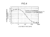
- the impedance of the load portion is sequentially changed. Therefore, in the configuration that a single power extraction coil is fixed, it is difficult to always accomplish good power transmission efficiency as illustrated in FIG. 4 .
- the load resistance is about 10 ohm, it is possible to obtain good power transmission efficiency of 0.8 or more. However, if the load resistance is 100 ohm, the power transmission efficiency becomes about 0.55; and if the load resistance is 1000 ohm, the power transmission efficiency becomes about 0.1.
- the power extraction coils 14-1 to 14-4 correspond to a change in load impedance and are different in terms of a diameter. For example, if the power extraction coils 14-1 to 14-4 are arrayed in a concentric shape, there is no need to newly secure additional space.
- the switch 31 installed between the power extraction coils 14-1 to 14-4 and the rectification circuit 32 selectively changes over the connection therebetween according to a command from the control circuit 35.
- Information used for sensing the load impedance seen from the magnetic field resonance system such as a voltage or a charging current of the battery 34 is input to the control circuit 35.
- the control circuit 35 selects a coil which is optimized with respect to the load impedance and stored in advance from the power extraction coils 14-1 to 14-4 based on the aforementioned information and issues a changing-over signal to the switch 31. According to the operations hereinbefore, even in the case where the load impedance is greatly changed as the charging of the battery 34 proceeds, it is possible to suppress deterioration or variation of the power transmission efficiency.
- FIG. 5 is a diagram for explaining power transmission efficiency with respect to the power reception apparatus 3.
- the power transmission efficiency E1 is higher than 0.8 at the load resistance of 10 ohm, and the power transmission efficiency E1 is lower than 0.6 from a load resistance higher than 100 ohm.
- the power transmission efficiency E2 is higher than 0.8 at the load resistance of 10 ohm, and the power transmission efficiency E2 is lower than 0.8 from a load resistance higher than 100 ohm.
- the power transmission efficiency E3 is higher than 0.8 at the load resistance of 100 ohm, and the power transmission efficiency E3 is lower than 0.5 from a load resistance higher than 1000 ohm.
- the power transmission efficiency E4 is about 0.8 at the load resistance of 100 ohm, and the power transmission efficiency E4 is maintained to be equal to or higher than 0.7 in a load resistance from 100 ohm to 1000 ohm.
- the power transmission efficiency E5 can be maintained to be equal to or higher than 0.7 in the range of a load resistance up to 1000 ohm.
- FIGS. 6 and 7 are diagrams for explaining specified examples of the power extraction coil.
- FIGS. 6 and 7 in order to simplify the description, three power extraction coils 14-1 to 14-3 are illustrated.
- a coil substrate 14a illustrated in FIG. 6 rectangular wire lines having the same center and different sizes are disposed on the first layer which is one surface of the substrate, so that the power extraction coils 14-1 to 14-3 are formed.
- the wire line is disconnected at one of the four corners, and the end portion is connected to the through-hole.
- a through-hole H11 is provided at the one end of the wire line corresponding to the power extraction coil 14-3.
- a wire line connected from the through-hole to an outer portion of the substrate is disposed on the other surface of the substrate, that is, the rear surface thereof.
- the wire line is a connection wire line used for connection to a load side.
- the one end portion of the two end portions of each of the three rectangular wire lines is connected to the same connection wire line. In this manner, the connection wire line shared by the three rectangular wire lines is always connected to the load side, and one of the remaining three wire lines is selected, so that the changing-over of the power extraction coils 14-1 to 14-3 is performed.
- a spiral rectangular wire line is disposed on the first layer which is one surface of the substrate.
- Two end portions of the spiral wire line are connected to through-holes.
- the end portion of the outer circumference side is the through-hole H12.
- two through-holes are disposed at two end portions in the path of the spiral wire line.
- a wire line connected from the through-hole to an outer portion of the substrate is disposed on the other surface of the substrate, that is, the rear surface thereof.
- the wire line is a connection wire line used for connection to a load side.
- the connection wire line connected to the through-hole H12 is always connected to the load side, and one of the remaining three through-holes is selected, so that the power extraction coils 14-1 to 14-3 are changed over. Therefore, the number of turns of the power extraction coil is changed.
- FIG. 8 is a diagram illustrating a circuit configuration of the power reception apparatus 3.
- FIG. 8 illustrates a circuit diagram in the case where the coil substrate 14a is used.
- the connection wire line shared by the three rectangular wire lines is connected to the rectification circuit 32.
- the remaining three connection wire lines are connected to the switch 31.
- the switch 31 changes over three connection wire lines in response to a command of the control circuit 35.
- the output of the rectification circuit 32 is input to the DD converter 33.
- a resistor (sense resistor) Rs for current detection is installed to one of two wire lines between the DD converter 33 and the battery 34.
- the control circuit 35 acquires a voltage which is to be supplied to the battery 34 and acquires voltages before and after the sense resistor Rs to calculate a current value. In addition, the control circuit 35 acquires a remaining amount from the battery 34. The control circuit 35 selects the to-be-used power extraction coil based on the supplied voltage, the current, and the remaining amount of the battery and outputs a change-over command to the switch 31, if necessary.
- FIG. 9 is a flowchart for explaining a process operation of the control circuit 35.
- the control circuit 35 detects a supply voltage, a current, and a remaining amount of a battery as a charging state (S101).
- the control circuit 35 selects a to-be-used power extraction coil based on the charging state (S102). If necessary, the control circuit 35 outputs a change-over command of the power extraction coil to the switch 31 (S103), and the process ends.
- the process operations are repetitively performed by the control circuit 35 during the charging of the battery 34.
- FIG. 10 is a diagram for explaining a modified example of the power reception/transmission system.
- a power reception apparatus 3a includes a power reception coil 13, one power extraction coil 15, a rectification circuit 32, a DD converter 33, a battery 34, a control circuit 35a, and a position control mechanism 36.
- the power reception apparatus 3a can adjust a distance between the power reception coil 13 and the power extraction coil 15 by changing the position of the power extraction coil 15 through the position control mechanism 36.
- the control circuit 35a controls the position control mechanism 36 based on the charging state of the battery 34, so that the power transmission efficiency can be maintained according to a change in load resistance.
- Other configurations and operations are similar to those of the power reception/transmission system 1 illustrated in FIG. 1 .
- the same components are denoted by the same reference numerals, and the description thereof is not provided.
- FIG. 11 is a diagram for explaining a modified example of the power reception/transmission system.
- a power reception/transmission system 1b illustrated in FIG. 11 includes a power transmission apparatus 2b and a power reception apparatus 3b.
- the power transmission apparatus 2b includes an AC power supply 21b and a power supply coil 16 in an inner portion thereof the power transmission apparatus 2b.
- the power reception apparatus 3 includes a power extraction coil 17, four power extraction coils 17, a switch 31, a rectification circuit 32, a DD converter 33, a battery 34, and a control circuit 35b.
- the control circuit 35b controls the switch 31 based on the charging state of the battery 34 to select one of the power extraction coils 17 so that energy transfer using electromagnetic induction is efficiently performed.
- the disclosed technique can be also applied to wireless power transmission using electromagnetic induction.
- Other configurations and operations are similar to those of the power reception/transmission system 1 illustrated in FIG. 1 .
- the same components are denoted by the same reference numerals, and the description thereof is not provided.
- the power reception apparatus 3 controls a diameter or position of the power extraction coil according to the charging state of the battery 34, so that it is possible to improve power supply efficiency in wireless power transmission using magnetic field resonance or electromagnetic induction.
- the embodiment is exemplary one, and thus, the configurations and operations may be appropriately modified.
- the battery 34 may be disposed outside the power reception apparatus 3.
- the battery 34 may be detachable.
- a plurality of power extraction coils having the same diameter and different distances from the power reception coil 13 or the power supply coil 16 may be disposed, and the power extraction coil is changed over according to the charging state.
- a plurality of the power extraction coils having different diameters and different distances may be disposed.
- the position of the power extraction coil is fixed, and the position of the power reception coil is controlled, so that the distance between the power extraction coil and the power reception coil is changed.
Landscapes
- Engineering & Computer Science (AREA)
- Power Engineering (AREA)
- Computer Networks & Wireless Communication (AREA)
- Transportation (AREA)
- Mechanical Engineering (AREA)
- Life Sciences & Earth Sciences (AREA)
- Sustainable Development (AREA)
- Sustainable Energy (AREA)
- Charge And Discharge Circuits For Batteries Or The Like (AREA)
- Secondary Cells (AREA)
Abstract
Description
- The present invention relates to a power reception apparatus and a power receiving method.
- In the related art, techniques of supplying power in a wireless manner by using electromagnetic induction or electromagnetic wave have been considered. Recently, techniques of supplying power in a wireless manner by using magnetic field resonance have been considered. The magnetic field resonance is a phenomenon where two resonating coils are coupled with each other through a magnetic field, so that energy transfer occurs. The magnetic field resonance is referred to as the resonance of a magnetic field.
-
- Patent Document 1: Japanese Laid-open Patent Publication No.
2009-106136 - Patent Document 2: Japanese National Publication of International Patent Application No.
2009-501510 - Patent Document 3: Japanese National Publication of International Patent Application No.
2002-544756 - Patent Document 4: Japanese Laid-open Patent Publication No.
2008-301918 - Patent Document 5: Japanese Laid-open Patent Publication No.
2008-160312 - Patent Document 6: Japanese Laid-open Patent Publication No.
2006-230129 - Energy is transferred between coils, and a load is connected to the coil at an energy extraction side, so that power can be supplied to the load. Power supply efficiency depends on impedance of the load.
- In the case where a battery is connected as the load, the impedance of the load is sequentially changed according to a charging state of the battery. Therefore, in the related art, there is a situation that the power supply efficiency is deteriorated in the period from the discharged state of the battery to the fully-charged state thereof.
- The technique disclosed in the present application is contrived by taking into consideration the above situation, and it is an object of the technique disclosed to provide a power reception apparatus and power receiving method capable of improving power supply efficiency with respect to a battery.
- According to a power reception apparatus and a power receiving method disclosed in the present application, the power reception apparatus includes a plurality of power extraction coils which extract power from a coil which is a power supply source and allows a switch to select one of the plurality of the power extraction coils and to connect the selected power extraction coil to a battery. The plurality of the power extraction coils are different from each other in terms of a diameter, a distance from the power extraction coil, or the number of turns (the number of windings). In the power reception apparatus and the power receiving method disclosed in the present application, a charging state of the battery is sensed, so that the switch is changed over.
- According to a power reception apparatus and a power receiving method disclosed in the present application, the power reception apparatus includes: a power extraction coil which extracts power from a coil which is a power supply source and charges a battery; and a position control mechanism which controls a positional relation between the coil which is the power supply source and the power extraction coil. In the power reception apparatus and power receiving method disclosed in the present application, a charging state of the battery is sensed, so that the position control mechanism is controlled.
- According to the power reception apparatus and the power receiving method disclosed in the present application, it is possible to improve power supply efficiency with respect to a battery.
-
-
FIG. 1 is a diagram illustrating a configuration of a power reception/transmission system including a power reception apparatus according to an embodiment. -
FIG. 2 is an equivalent circuit diagram illustrating a magnetic field resonance type power reception/transmission system including four coils illustrated inFIG. 1 . -
FIG. 3 is a diagram for explaining a sequence of charging a lithium ion battery. -
FIG. 4 is a diagram for explaining deterioration in power transmission efficiency according to variation of load. -
FIG. 5 is a diagram for explaining power transmission efficiency with respect to apower reception apparatus 3. -
FIG. 6 is a diagram for explaining a specified example of a power extraction coil (first example thereof). -
FIG. 7 is a diagram for explaining a specified example of a power extraction coil (second example thereof). -
FIG. 8 is a diagram illustrating a circuit configuration of apower reception apparatus 3. -
FIG. 9 is a flowchart for explaining a process operation of acontrol circuit 35. -
FIG. 10 is a diagram for explaining a modified example of a power reception/transmission system (first example thereof). -
FIG. 11 is a diagram for explaining a modified example of a power reception/transmission system (second example thereof). - Preferred embodiments of the present invention will be explained with reference to accompanying drawings. In addition, the embodiments do not limit the technique disclosed herein.
-
FIG. 1 is a diagram illustrating a configuration of a power reception/transmission system including a power reception apparatus according to an embodiment.FIG. 2 is an equivalent circuit diagram illustrating a magnetic field resonance type power reception/transmission system including four coils illustrated inFIG. 1 . The power reception/transmission system 1 illustrated inFIG. 1 includes apower transmission apparatus 2 and apower reception apparatus 3. Thepower transmission apparatus 2 includes anAC power supply 21, apower supply coil 11, and apower transmission coil 12 in an inner portion of thepower transmission apparatus 2. In addition, thepower reception apparatus 3 includes apower reception coil 13, four power extraction coils 14-1 to 14-4, aswitch 31, arectification circuit 32, a DC-to-DC (DD)converter 33, a battery (rechargeable battery) 34, and acontrol circuit 35. - The
power transmission coil 12 and the power reception coil 13 form an LC resonance circuit. A condenser component of the LC resonance circuit may be implemented with an element. Otherwise, the condenser component may be implemented with floating capacitance formed by opening the two ends of the coil. In the LC resonance circuit, when inductance and condenser capacitance are denoted by L and C, respectively, a resonance frequency f is defined as follows.
- In the case where the resonance frequency of the
power transmission coil 12 and the resonance frequency of thepower reception coil 13 are sufficiently close to each other and a distance between thepower transmission coil 12 and thepower reception coil 13 is sufficiently small, magnetic field resonance may occur between thepower transmission coil 12 and thepower reception coil 13. - Therefore, when the magnetic field resonance occurs in the state where the
power transmission coil 12 is resonating, magnetic field energy may be transferred from thepower transmission coil 12 to thepower reception coil 13. In the magnetic field resonance type, there are advantages in that large power can be transmitted in comparison with the case using electromagnetic wave and a long transfer distance can be obtained in comparison with the electromagnetic induction type. - The
power supply coil 11 supplies the power, which is acquired from theAC power supply 21, to thepower transmission coil 12 according to electromagnetic induction. In the arrangement of thepower supply coil 11 and thepower transmission coil 12, the distance and arrangement are configured so that the electromagnetic induction can occur. Since thepower transmission coil 12 is allowed to resonate through thepower supply coil 11 according to the electromagnetic induction, there is no need to electrically connect thepower transmission coil 12 and other circuits. Therefore, the resonance frequency of thepower transmission coil 12 can be designed to be an arbitrary value with high accuracy. - The power extraction coils 14-1 to 14-4 are disposed at positions where electromagnetic induction occurs with respect to the
power reception coil 13. Theswitch 31 selects one of the power extraction coils 14-1 to 14-4 and connects the selected power extraction coil to therectification circuit 32. When thepower reception coil 13 resonates according to the magnetic field resonance, energy is transferred due to the electromagnetic induction from thepower reception coil 13 to the power extraction coil selected by theswitch 31 among the power extraction coils 14-1 to 14-4. The energy transferred to the power extraction coil selected by theswitch 31 is extracted as power, and the power is supplied through theswitch 31, therectification circuit 32, and theDD converter 33 to thebattery 34. - In this manner, since the power is extracted from the
power reception coil 13 through the power extraction coils 14-1 to 14-4 according to the electromagnetic induction, there is no need to electrically connect thepower reception coil 13 and other circuits. Therefore, the resonance frequency of thepower reception coil 13 can be designed to be an arbitrary value at high accuracy. - The
AC power supply 21 outputs an AC current having a predetermined frequency and amplitude. Hereinafter, the frequency of theAC power supply 21 is referred to as a driving frequency. Apower supply coil 11 electrically connected to theAC power supply 21 is allowed to vibrate at the driving frequency. Therefore, thepower transmission coil 12 is allowed to resonate at the driving frequency. Similarly, thepower reception coil 13 is also allowed to resonate at the driving frequency. - In this manner, in the power reception/
transmission system 1, the power of theAC power supply 21 is extracted as power according to the electromagnetic induction between thepower supply coil 11 and thepower transmission coil 12, the magnetic field resonance between thepower transmission coil 12 and thepower reception coil 13, and the electromagnetic induction between thepower reception coil 13 and the power extraction coils 14-1 to 14-4. The extracted power is converted into DC power by therectification circuit 32 and converted into a voltage by theDD converter 33 to be used for charging thebattery 34. - As performance required for wireless power transmission, there is power transmission efficiency from a power transmission portion to a power reception portion. In the example illustrated in
FIGS. 1 and2 , the power transmission efficiency is defined as a ratio of power consumed by a load resistor connected to apower extraction coil 14 to an effective power input to apower supply coil 11. - In the case where power is supplied to a mobile apparatus such as a mobile phone or an electric vehicle (EV), a load resistor portion is configured to include a
rectification circuit 32, aDD converter 33, and abattery 34. In general, as illustrated inFIG. 3 , in a sequence of charging a lithium ion battery, constant-current charging is performed when the battery is close to a discharged state, and constant-voltage charging is performed when a charged amount reaches a certain amount. In this case, as seen from a magnetic field resonance type wireless power transmission system, the impedance of the load portion is sequentially changed. Therefore, in the configuration that a single power extraction coil is fixed, it is difficult to always accomplish good power transmission efficiency as illustrated inFIG. 4 . - In the example illustrated in
FIG. 4 , if the load resistance is about 10 ohm, it is possible to obtain good power transmission efficiency of 0.8 or more. However, if the load resistance is 100 ohm, the power transmission efficiency becomes about 0.55; and if the load resistance is 1000 ohm, the power transmission efficiency becomes about 0.1. - Therefore, in the
power reception apparatus 3 illustrated inFig. 1 , in order to suppress deterioration or variation in power transmission efficiency according to a change in charged amount of thebattery 34, that is, a change in load impedance, changing-over of the power extraction coils 14-1 to 14-4 is controlled according to the charging state of thebattery 34. - The power extraction coils 14-1 to 14-4 correspond to a change in load impedance and are different in terms of a diameter. For example, if the power extraction coils 14-1 to 14-4 are arrayed in a concentric shape, there is no need to newly secure additional space.
- The
switch 31 installed between the power extraction coils 14-1 to 14-4 and therectification circuit 32 selectively changes over the connection therebetween according to a command from thecontrol circuit 35. Information used for sensing the load impedance seen from the magnetic field resonance system such as a voltage or a charging current of thebattery 34 is input to thecontrol circuit 35. Thecontrol circuit 35 selects a coil which is optimized with respect to the load impedance and stored in advance from the power extraction coils 14-1 to 14-4 based on the aforementioned information and issues a changing-over signal to theswitch 31. According to the operations hereinbefore, even in the case where the load impedance is greatly changed as the charging of thebattery 34 proceeds, it is possible to suppress deterioration or variation of the power transmission efficiency. -
FIG. 5 is a diagram for explaining power transmission efficiency with respect to thepower reception apparatus 3. In the case where the power extraction coil 14-1 having the smallest diameter is used, the power transmission efficiency E1 is higher than 0.8 at the load resistance of 10 ohm, and the power transmission efficiency E1 is lower than 0.6 from a load resistance higher than 100 ohm. Next, in the case where the power extraction coil 14-2 having a second smallest diameter is used, the power transmission efficiency E2 is higher than 0.8 at the load resistance of 10 ohm, and the power transmission efficiency E2 is lower than 0.8 from a load resistance higher than 100 ohm. Next, in the case where the power extraction coil 14-3 having a third smallest diameter is used, the power transmission efficiency E3 is higher than 0.8 at the load resistance of 100 ohm, and the power transmission efficiency E3 is lower than 0.5 from a load resistance higher than 1000 ohm. In the case where the power extraction coil 14-4 having the largest diameter is used, the power transmission efficiency E4 is about 0.8 at the load resistance of 100 ohm, and the power transmission efficiency E4 is maintained to be equal to or higher than 0.7 in a load resistance from 100 ohm to 1000 ohm. - Therefore, in the case where the power extraction coils 14-1 to 14-4 are changed over according to the load resistance, the power transmission efficiency E5 can be maintained to be equal to or higher than 0.7 in the range of a load resistance up to 1000 ohm.
-
FIGS. 6 and 7 are diagrams for explaining specified examples of the power extraction coil. InFIGS. 6 and 7 , in order to simplify the description, three power extraction coils 14-1 to 14-3 are illustrated. - In a
coil substrate 14a illustrated inFIG. 6 , rectangular wire lines having the same center and different sizes are disposed on the first layer which is one surface of the substrate, so that the power extraction coils 14-1 to 14-3 are formed. In each rectangle, the wire line is disconnected at one of the four corners, and the end portion is connected to the through-hole. In the example illustrated inFIG. 6 , among the through-holes, a through-hole H11 is provided at the one end of the wire line corresponding to the power extraction coil 14-3. - In the
coil substrate 14a, a wire line connected from the through-hole to an outer portion of the substrate is disposed on the other surface of the substrate, that is, the rear surface thereof. The wire line is a connection wire line used for connection to a load side. In addition, on the rear surface of thecoil substrate 14a, the one end portion of the two end portions of each of the three rectangular wire lines is connected to the same connection wire line. In this manner, the connection wire line shared by the three rectangular wire lines is always connected to the load side, and one of the remaining three wire lines is selected, so that the changing-over of the power extraction coils 14-1 to 14-3 is performed. - In a coil substrate 14b illustrated in
FIG. 7 , a spiral rectangular wire line is disposed on the first layer which is one surface of the substrate. Two end portions of the spiral wire line are connected to through-holes. Among the through-holes, the end portion of the outer circumference side is the through-hole H12. In addition, on the coil substrate 14b, two through-holes are disposed at two end portions in the path of the spiral wire line. - In addition, in the coil substrate 14b, a wire line connected from the through-hole to an outer portion of the substrate is disposed on the other surface of the substrate, that is, the rear surface thereof. The wire line is a connection wire line used for connection to a load side. On the coil substrate 14b, the connection wire line connected to the through-hole H12 is always connected to the load side, and one of the remaining three through-holes is selected, so that the power extraction coils 14-1 to 14-3 are changed over. Therefore, the number of turns of the power extraction coil is changed.
-
FIG. 8 is a diagram illustrating a circuit configuration of thepower reception apparatus 3.FIG. 8 illustrates a circuit diagram in the case where thecoil substrate 14a is used. The connection wire line shared by the three rectangular wire lines is connected to therectification circuit 32. The remaining three connection wire lines are connected to theswitch 31. - The
switch 31 changes over three connection wire lines in response to a command of thecontrol circuit 35. The output of therectification circuit 32 is input to theDD converter 33. A resistor (sense resistor) Rs for current detection is installed to one of two wire lines between theDD converter 33 and thebattery 34. - The
control circuit 35 acquires a voltage which is to be supplied to thebattery 34 and acquires voltages before and after the sense resistor Rs to calculate a current value. In addition, thecontrol circuit 35 acquires a remaining amount from thebattery 34. Thecontrol circuit 35 selects the to-be-used power extraction coil based on the supplied voltage, the current, and the remaining amount of the battery and outputs a change-over command to theswitch 31, if necessary. -
FIG. 9 is a flowchart for explaining a process operation of thecontrol circuit 35. In the process starts, thecontrol circuit 35 detects a supply voltage, a current, and a remaining amount of a battery as a charging state (S101). Next, thecontrol circuit 35 selects a to-be-used power extraction coil based on the charging state (S102).
If necessary, thecontrol circuit 35 outputs a change-over command of the power extraction coil to the switch 31 (S103), and the process ends. In addition, the process operations are repetitively performed by thecontrol circuit 35 during the charging of thebattery 34. -
FIG. 10 is a diagram for explaining a modified example of the power reception/transmission system. In a power reception/transmission system 1a illustrated inFIG. 10 , apower reception apparatus 3a includes apower reception coil 13, onepower extraction coil 15, arectification circuit 32, aDD converter 33, abattery 34, acontrol circuit 35a, and aposition control mechanism 36. - The
power reception apparatus 3a can adjust a distance between thepower reception coil 13 and thepower extraction coil 15 by changing the position of thepower extraction coil 15 through theposition control mechanism 36. Thecontrol circuit 35a controls theposition control mechanism 36 based on the charging state of thebattery 34, so that the power transmission efficiency can be maintained according to a change in load resistance. Other configurations and operations are similar to those of the power reception/transmission system 1 illustrated inFIG. 1 . The same components are denoted by the same reference numerals, and the description thereof is not provided. -
FIG. 11 is a diagram for explaining a modified example of the power reception/transmission system. A power reception/transmission system 1b illustrated inFIG. 11 includes apower transmission apparatus 2b and apower reception apparatus 3b. Thepower transmission apparatus 2b includes anAC power supply 21b and apower supply coil 16 in an inner portion thereof thepower transmission apparatus 2b. In addition, thepower reception apparatus 3 includes apower extraction coil 17, four power extraction coils 17, aswitch 31, arectification circuit 32, aDD converter 33, abattery 34, and acontrol circuit 35b. - In the power reception/
transmission system 1b, energy transfer using electromagnetic induction is performed from thepower supply coil 16 of thepower transmission apparatus 2b to the power extraction coils 17 of thepower reception apparatus 3b. Therefore, thecontrol circuit 35b controls theswitch 31 based on the charging state of thebattery 34 to select one of the power extraction coils 17 so that energy transfer using electromagnetic induction is efficiently performed. In this manner, the disclosed technique can be also applied to wireless power transmission using electromagnetic induction. Other configurations and operations are similar to those of the power reception/transmission system 1 illustrated inFIG. 1 . The same components are denoted by the same reference numerals, and the description thereof is not provided. - As described above, in the power reception/
transmission system 1 according to the embodiment, since thepower reception apparatus 3 controls a diameter or position of the power extraction coil according to the charging state of thebattery 34, so that it is possible to improve power supply efficiency in wireless power transmission using magnetic field resonance or electromagnetic induction. - In addition, the embodiment is exemplary one, and thus, the configurations and operations may be appropriately modified. For example, the
battery 34 may be disposed outside thepower reception apparatus 3. In addition, thebattery 34 may be detachable. - In addition, in a configuration, a plurality of power extraction coils having the same diameter and different distances from the
power reception coil 13 or thepower supply coil 16 may be disposed, and the power extraction coil is changed over according to the charging state. In addition, in another configuration, a plurality of the power extraction coils having different diameters and different distances may be disposed. In addition, in still another configuration, the position of the power extraction coil is fixed, and the position of the power reception coil is controlled, so that the distance between the power extraction coil and the power reception coil is changed. -
- 1, 1a:
- power reception/transmission system
- 2, 2b:
- power transmission apparatus
- 3, 3b:
- power reception apparatus
- 11, 16:
- power supply coil
- 12:
- power transmission coil
- 13:
- power reception coil
- 14_1 to 14_4, 15, 17:
- power extraction coil
- 14a, 14b:
- coil substrate
- 21, 21b:
- AC power supply
- 31:
- switch
- 32:
- rectification circuit
- 33:
- DD converter
- 34:
- battery
- 35, 35a, 35b:
- control circuit
- 36:
- position control mechanism
Claims (5)
- A power reception apparatus comprising:a plurality of power extraction coils that extract power from a coil being a power supply source;a switch that selects one of the plurality of the power extraction coils and connects the selected power extraction coil to a battery; anda controller that senses a charging state of the battery and changes over the switch,wherein the plurality of the power extraction coils are different from each other in terms of a diameter, the number of turns, or a distance from the power extraction coil.
- A power reception apparatus comprising:a power extraction coil that extracts power from a coil being a power supply source and charges a battery;a position control mechanism that controls a positional relation between the coil being the power supply source and the power extraction coil; anda controller that senses a charging state of the battery and controls the position control mechanism.
- The power reception apparatus according to claim 1 or 2, wherein the coil being the power supply source is installed in an inner portion of the power reception apparatus, and the coil being the power supply source receives power from a coil outside the power reception apparatus using magnetic field resonance.
- A power receiving method comprising the steps of:sensing a charging state of a battery connected to one of a plurality of power extraction coils that extract power from a coil being a power supply source;selecting one of the plurality of the power extraction coils based on the charging state of the battery; andchanging over a connection relation between the plurality of the power extraction coils and the battery based on a result of the selecting.
- A power receiving method comprising the steps of:sensing a charging state of a battery connected to a power extraction coil that extracts power from a coil being a power supply source;determining a distance between the coil being the power supply source and the power extraction coil based on the charging state of the battery; andcontrolling a positional relation between the coil being the power supply source and the power extraction coil based on the determined distance.
Applications Claiming Priority (1)
| Application Number | Priority Date | Filing Date | Title |
|---|---|---|---|
| PCT/JP2010/057702 WO2011135722A1 (en) | 2010-04-30 | 2010-04-30 | Power receiving device and power receiving method |
Publications (2)
| Publication Number | Publication Date |
|---|---|
| EP2566011A1 true EP2566011A1 (en) | 2013-03-06 |
| EP2566011A4 EP2566011A4 (en) | 2015-06-10 |
Family
ID=44861061
Family Applications (1)
| Application Number | Title | Priority Date | Filing Date |
|---|---|---|---|
| EP10850737.7A Withdrawn EP2566011A4 (en) | 2010-04-30 | 2010-04-30 | ELECTRIC POWER RECEIVING DEVICE AND ELECTRIC POWER RECEIVING METHOD |
Country Status (8)
| Country | Link |
|---|---|
| US (1) | US9831681B2 (en) |
| EP (1) | EP2566011A4 (en) |
| JP (1) | JP5527407B2 (en) |
| KR (1) | KR101391487B1 (en) |
| CN (1) | CN102870315B (en) |
| BR (1) | BR112012027696A2 (en) |
| MX (1) | MX2012012609A (en) |
| WO (1) | WO2011135722A1 (en) |
Cited By (2)
| Publication number | Priority date | Publication date | Assignee | Title |
|---|---|---|---|---|
| WO2016094023A1 (en) * | 2014-12-12 | 2016-06-16 | Qualcomm Incorporated | Wearable devices for wireless power transfer and communication |
| EP3442107A4 (en) * | 2016-04-06 | 2019-12-04 | Hitachi, Ltd. | WIRELESS CURRENT TRANSMISSION AND RECEPTION SYSTEM, CURRENT CONVERTING APPARATUS HAVING THE SAME, AND CURRENT CONVERTING METHOD |
Families Citing this family (20)
| Publication number | Priority date | Publication date | Assignee | Title |
|---|---|---|---|---|
| WO2011135722A1 (en) * | 2010-04-30 | 2011-11-03 | 富士通株式会社 | Power receiving device and power receiving method |
| US8725330B2 (en) | 2010-06-02 | 2014-05-13 | Bryan Marc Failing | Increasing vehicle security |
| US20130127406A1 (en) * | 2011-11-18 | 2013-05-23 | Research In Motion Limited | Method and system for inductively charging an electronic device |
| KR20130081620A (en) | 2012-01-09 | 2013-07-17 | 주식회사 케이더파워 | The reciving set for the wireless charging system |
| WO2013114576A1 (en) | 2012-01-31 | 2013-08-08 | 富士通株式会社 | Power transmission device, power transmission system, and power transmission method |
| JPWO2013136409A1 (en) * | 2012-03-12 | 2015-07-30 | パイオニア株式会社 | Power receiving device, power receiving device control method, and computer program |
| US9362776B2 (en) * | 2012-11-27 | 2016-06-07 | Qualcomm Incorporated | Wireless charging systems and methods |
| KR101462138B1 (en) * | 2013-05-16 | 2014-11-21 | 재단법인 포항산업과학연구원 | Underwater wireless power transmission system using the electromagnetic coupled resonance method |
| JP6111160B2 (en) * | 2013-07-18 | 2017-04-05 | 本田技研工業株式会社 | Electric vehicle |
| KR20150050142A (en) * | 2013-10-31 | 2015-05-08 | 삼성전기주식회사 | Electronic device |
| US10004913B2 (en) * | 2014-03-03 | 2018-06-26 | The Board Of Trustees Of The Leland Stanford Junior University | Methods and apparatus for power conversion and data transmission in implantable sensors, stimulators, and actuators |
| US9673658B2 (en) * | 2014-03-06 | 2017-06-06 | Samsung Electro-Mechanics Co., Ltd. | Non-contact capacitive coupling type power charging apparatus and non-contact capacitive coupling type battery apparatus |
| US10434329B2 (en) | 2014-05-09 | 2019-10-08 | The Board Of Trustees Of The Leland Stanford Junior University | Autofocus wireless power transfer to implantable devices in freely moving animals |
| CN106471707B (en) | 2014-05-15 | 2018-04-03 | 日产自动车株式会社 | Contactless power supply device |
| US9852843B2 (en) | 2014-07-14 | 2017-12-26 | Qualcomm Incorporated | Method and apparatus for adjustable coupling for improved wireless high Q resonant power transfer |
| GB2531505A (en) | 2014-10-09 | 2016-04-27 | Bombardier Transp Gmbh | A method of operating an inductive power transfer system and an inductive power transfer system |
| KR102154251B1 (en) * | 2016-10-11 | 2020-09-09 | 주식회사 아모센스 | Electromagnetic inductive power supply apparatus |
| CN107093929B (en) * | 2017-03-24 | 2021-10-22 | 哈尔滨工业大学深圳研究生院 | Coupled resonance underwater wireless charging device and method |
| JP6855878B2 (en) | 2017-03-29 | 2021-04-07 | 富士通株式会社 | Power receiver, power transmission system, and power receiver control method |
| CN111416447A (en) * | 2019-01-04 | 2020-07-14 | 上海卡珀林智能科技有限公司 | Dual resonance wireless power transmission system and method with adjustable receiver coil |
Family Cites Families (28)
| Publication number | Priority date | Publication date | Assignee | Title |
|---|---|---|---|---|
| JP3747677B2 (en) * | 1998-03-03 | 2006-02-22 | セイコーエプソン株式会社 | Electronics |
| US6316909B1 (en) | 1998-03-24 | 2001-11-13 | Seiko Epson Corporation | Electronic device, control method for electronic device, recharge-rate estimating method for secondary battery, and charging control method for secondary battery |
| US6163242A (en) * | 1999-05-07 | 2000-12-19 | Scanditronix Medical Ab | Rotationally symmetrical high-voltage pulse transformer with tesla resonance and energy recovery |
| JP2003168088A (en) * | 2001-11-29 | 2003-06-13 | Matsushita Electric Ind Co Ltd | Non-contact IC card |
| US7256695B2 (en) * | 2002-09-23 | 2007-08-14 | Microstrain, Inc. | Remotely powered and remotely interrogated wireless digital sensor telemetry system |
| US6917182B2 (en) * | 2003-07-24 | 2005-07-12 | Motorola, Inc. | Method and system for providing induction charging having improved efficiency |
| JP2005057270A (en) * | 2003-08-01 | 2005-03-03 | Stmicroelectronics Sa | Switchable inductance |
| JP4036813B2 (en) * | 2003-09-30 | 2008-01-23 | シャープ株式会社 | Non-contact power supply system |
| JP4639773B2 (en) * | 2004-11-24 | 2011-02-23 | 富士電機ホールディングス株式会社 | Non-contact power feeding device |
| JP2006230129A (en) * | 2005-02-18 | 2006-08-31 | Nanao Corp | Noncontact power supply |
| JP4318044B2 (en) * | 2005-03-03 | 2009-08-19 | ソニー株式会社 | Power supply system, power supply apparatus and method, power reception apparatus and method, recording medium, and program |
| KR101118710B1 (en) | 2005-07-12 | 2012-03-13 | 메사추세츠 인스티튜트 오브 테크놀로지 | Wireless non-radiative energy transfer |
| US8633577B2 (en) | 2006-01-24 | 2014-01-21 | Renesas Electronics Corporation | Integrated circuit device |
| US8169185B2 (en) * | 2006-01-31 | 2012-05-01 | Mojo Mobility, Inc. | System and method for inductive charging of portable devices |
| JP2008160312A (en) * | 2006-12-21 | 2008-07-10 | Toshiba Corp | Wireless communication device |
| JP2008301645A (en) * | 2007-06-01 | 2008-12-11 | Sanyo Electric Co Ltd | Non-contact power receiving apparatus and electronic apparatus therewith |
| JP5118895B2 (en) * | 2007-06-06 | 2013-01-16 | 株式会社根本杏林堂 | Electric medical system, power receiving medical unit and power transmission unit |
| GB0716679D0 (en) * | 2007-08-28 | 2007-10-03 | Fells J | Inductive power supply |
| JP4453741B2 (en) * | 2007-10-25 | 2010-04-21 | トヨタ自動車株式会社 | Electric vehicle and vehicle power supply device |
| US8244367B2 (en) * | 2007-10-26 | 2012-08-14 | Medtronic, Inc. | Closed loop long range recharging |
| WO2009114671A1 (en) * | 2008-03-13 | 2009-09-17 | Access Business Group International Llc | Inductive power supply system with multiple coil primary |
| US20110050164A1 (en) * | 2008-05-07 | 2011-03-03 | Afshin Partovi | System and methods for inductive charging, and improvements and uses thereof |
| JP2009273327A (en) * | 2008-05-10 | 2009-11-19 | Sanyo Electric Co Ltd | Battery built-in apparatus and charging cradle |
| US8278784B2 (en) * | 2008-07-28 | 2012-10-02 | Qualcomm Incorporated | Wireless power transmission for electronic devices |
| JP4911148B2 (en) * | 2008-09-02 | 2012-04-04 | ソニー株式会社 | Contactless power supply |
| WO2010036980A1 (en) * | 2008-09-27 | 2010-04-01 | Witricity Corporation | Wireless energy transfer systems |
| CN102449711A (en) | 2009-07-02 | 2012-05-09 | 丰田自动车株式会社 | Coil unit, noncontact power receiving device, noncontact power feeding device, noncontact power feeding system, and vehicle |
| WO2011135722A1 (en) * | 2010-04-30 | 2011-11-03 | 富士通株式会社 | Power receiving device and power receiving method |
-
2010
- 2010-04-30 WO PCT/JP2010/057702 patent/WO2011135722A1/en not_active Ceased
- 2010-04-30 EP EP10850737.7A patent/EP2566011A4/en not_active Withdrawn
- 2010-04-30 BR BR112012027696A patent/BR112012027696A2/en not_active Application Discontinuation
- 2010-04-30 JP JP2012512610A patent/JP5527407B2/en not_active Expired - Fee Related
- 2010-04-30 CN CN201080066538.2A patent/CN102870315B/en not_active Expired - Fee Related
- 2010-04-30 KR KR1020127026826A patent/KR101391487B1/en not_active Expired - Fee Related
- 2010-04-30 MX MX2012012609A patent/MX2012012609A/en active IP Right Grant
-
2012
- 2012-10-15 US US13/651,831 patent/US9831681B2/en not_active Expired - Fee Related
Non-Patent Citations (1)
| Title |
|---|
| See references of WO2011135722A1 * |
Cited By (4)
| Publication number | Priority date | Publication date | Assignee | Title |
|---|---|---|---|---|
| WO2016094023A1 (en) * | 2014-12-12 | 2016-06-16 | Qualcomm Incorporated | Wearable devices for wireless power transfer and communication |
| US9882413B2 (en) | 2014-12-12 | 2018-01-30 | Qualcomm Incorporated | Wearable devices for wireless power transfer and communication |
| EP3442107A4 (en) * | 2016-04-06 | 2019-12-04 | Hitachi, Ltd. | WIRELESS CURRENT TRANSMISSION AND RECEPTION SYSTEM, CURRENT CONVERTING APPARATUS HAVING THE SAME, AND CURRENT CONVERTING METHOD |
| US11018528B2 (en) | 2016-04-06 | 2021-05-25 | Hitachi, Ltd. | Wireless power transmission/reception system, power conversion device including the same, and power conversion method |
Also Published As
| Publication number | Publication date |
|---|---|
| US20130038282A1 (en) | 2013-02-14 |
| KR20120135519A (en) | 2012-12-14 |
| BR112012027696A2 (en) | 2016-08-16 |
| KR101391487B1 (en) | 2014-05-07 |
| CN102870315A (en) | 2013-01-09 |
| EP2566011A4 (en) | 2015-06-10 |
| JP5527407B2 (en) | 2014-06-18 |
| MX2012012609A (en) | 2012-12-17 |
| CN102870315B (en) | 2016-06-01 |
| JPWO2011135722A1 (en) | 2013-07-18 |
| WO2011135722A1 (en) | 2011-11-03 |
| US9831681B2 (en) | 2017-11-28 |
Similar Documents
| Publication | Publication Date | Title |
|---|---|---|
| EP2566011A1 (en) | Power receiving device and power receiving method | |
| US8222860B2 (en) | Power transmission control device, power transmission device, power receiving control device, power receiving device, and electronic apparatus | |
| US8274254B2 (en) | Power transmission control device, power transmission device, power receiving control device, power receiving device, electronic apparatus, method for controlling power transmission, and method for controlling power receiving | |
| JP5826547B2 (en) | Power supply side equipment and resonance type non-contact power supply system | |
| EP2587613B1 (en) | Wireless power receiver for adjusting magnitude of wireless power | |
| US10833538B2 (en) | Electronic unit and power feeding system | |
| US8369905B2 (en) | Power transmission control device, power transmission device, power receiving control device, power receiving device, and electronic apparatus | |
| CN104253491B (en) | Power transmission device, non-contact power supply system, and control method | |
| EP2736148B1 (en) | Non-contact power supply system | |
| JP6001355B2 (en) | Non-contact power feeding device | |
| CN104247205B (en) | Power supply device and power supply receiving system | |
| US20130225082A1 (en) | Apparatus and method for wireless power transmission | |
| US20130257167A1 (en) | Apparatuses, systems, and methods for power transfer adjustment in wireless power transfer systems | |
| EP3229343A1 (en) | Contactless power supply system | |
| JP2010183812A (en) | Resonance type non-contact charging system | |
| EP3054559A1 (en) | Power transmission apparatus | |
| US9148024B2 (en) | Apparatuses, systems, and methods for a monotonic transfer function in wireless power transfer systems | |
| JP2012138976A (en) | Power transmission system | |
| WO2013094463A1 (en) | Power supply device, power supply system, and electronic apparatus | |
| KR20170109299A (en) | Resonance apparatus and apparatus for transmitting power wirelessly using the same | |
| US10923273B2 (en) | Coil design for wireless power transfer | |
| JP2013021887A (en) | Electric power transmission system | |
| WO2014030689A1 (en) | Non-contact power transmission device and power-receiving apparatus | |
| KR20150057057A (en) | Ac cable for wireless charging and method for wireless charging with ac cable |
Legal Events
| Date | Code | Title | Description |
|---|---|---|---|
| PUAI | Public reference made under article 153(3) epc to a published international application that has entered the european phase |
Free format text: ORIGINAL CODE: 0009012 |
|
| 17P | Request for examination filed |
Effective date: 20121126 |
|
| AK | Designated contracting states |
Kind code of ref document: A1 Designated state(s): AT BE BG CH CY CZ DE DK EE ES FI FR GB GR HR HU IE IS IT LI LT LU LV MC MK MT NL NO PL PT RO SE SI SK SM TR |
|
| DAX | Request for extension of the european patent (deleted) | ||
| RA4 | Supplementary search report drawn up and despatched (corrected) |
Effective date: 20150511 |
|
| RIC1 | Information provided on ipc code assigned before grant |
Ipc: H01F 38/14 20060101ALI20150504BHEP Ipc: B60L 11/18 20060101ALI20150504BHEP Ipc: H02J 5/00 20060101ALI20150504BHEP Ipc: H02J 17/00 20060101AFI20150504BHEP Ipc: H02J 7/02 20060101ALI20150504BHEP Ipc: H02J 7/00 20060101ALI20150504BHEP |
|
| 17Q | First examination report despatched |
Effective date: 20160923 |
|
| STAA | Information on the status of an ep patent application or granted ep patent |
Free format text: STATUS: EXAMINATION IS IN PROGRESS |
|
| STAA | Information on the status of an ep patent application or granted ep patent |
Free format text: STATUS: THE APPLICATION IS DEEMED TO BE WITHDRAWN |
|
| 18D | Application deemed to be withdrawn |
Effective date: 20190226 |