EP2565888A1 - Contact member and switch device using contact member - Google Patents
Contact member and switch device using contact member Download PDFInfo
- Publication number
- EP2565888A1 EP2565888A1 EP11774790A EP11774790A EP2565888A1 EP 2565888 A1 EP2565888 A1 EP 2565888A1 EP 11774790 A EP11774790 A EP 11774790A EP 11774790 A EP11774790 A EP 11774790A EP 2565888 A1 EP2565888 A1 EP 2565888A1
- Authority
- EP
- European Patent Office
- Prior art keywords
- curved portion
- center
- contact member
- protrusions
- member according
- Prior art date
- Legal status (The legal status is an assumption and is not a legal conclusion. Google has not performed a legal analysis and makes no representation as to the accuracy of the status listed.)
- Granted
Links
Images




Classifications
-
- H—ELECTRICITY
- H01—ELECTRIC ELEMENTS
- H01H—ELECTRIC SWITCHES; RELAYS; SELECTORS; EMERGENCY PROTECTIVE DEVICES
- H01H13/00—Switches having rectilinearly-movable operating part or parts adapted for pushing or pulling in one direction only, e.g. push-button switch
- H01H13/70—Switches having rectilinearly-movable operating part or parts adapted for pushing or pulling in one direction only, e.g. push-button switch having a plurality of operating members associated with different sets of contacts, e.g. keyboard
- H01H13/84—Switches having rectilinearly-movable operating part or parts adapted for pushing or pulling in one direction only, e.g. push-button switch having a plurality of operating members associated with different sets of contacts, e.g. keyboard characterised by ergonomic functions, e.g. for miniature keyboards; characterised by operational sensory functions, e.g. sound feedback
- H01H13/85—Switches having rectilinearly-movable operating part or parts adapted for pushing or pulling in one direction only, e.g. push-button switch having a plurality of operating members associated with different sets of contacts, e.g. keyboard characterised by ergonomic functions, e.g. for miniature keyboards; characterised by operational sensory functions, e.g. sound feedback characterised by tactile feedback features
-
- H—ELECTRICITY
- H01—ELECTRIC ELEMENTS
- H01H—ELECTRIC SWITCHES; RELAYS; SELECTORS; EMERGENCY PROTECTIVE DEVICES
- H01H13/00—Switches having rectilinearly-movable operating part or parts adapted for pushing or pulling in one direction only, e.g. push-button switch
- H01H13/02—Details
- H01H13/26—Snap-action arrangements depending upon deformation of elastic members
- H01H13/48—Snap-action arrangements depending upon deformation of elastic members using buckling of disc springs
-
- H—ELECTRICITY
- H01—ELECTRIC ELEMENTS
- H01H—ELECTRIC SWITCHES; RELAYS; SELECTORS; EMERGENCY PROTECTIVE DEVICES
- H01H2203/00—Form of contacts
- H01H2203/012—Microprotrusions
-
- H—ELECTRICITY
- H01—ELECTRIC ELEMENTS
- H01H—ELECTRIC SWITCHES; RELAYS; SELECTORS; EMERGENCY PROTECTIVE DEVICES
- H01H2215/00—Tactile feedback
- H01H2215/004—Collapsible dome or bubble
- H01H2215/006—Only mechanical function
-
- H—ELECTRICITY
- H01—ELECTRIC ELEMENTS
- H01H—ELECTRIC SWITCHES; RELAYS; SELECTORS; EMERGENCY PROTECTIVE DEVICES
- H01H2215/00—Tactile feedback
- H01H2215/004—Collapsible dome or bubble
- H01H2215/022—Asymmetric; Elliptic; Square
-
- H—ELECTRICITY
- H01—ELECTRIC ELEMENTS
- H01H—ELECTRIC SWITCHES; RELAYS; SELECTORS; EMERGENCY PROTECTIVE DEVICES
- H01H2227/00—Dimensions; Characteristics
- H01H2227/026—Separate dome contact
Definitions
- the present invention relates to a contact member having a curved portion which is formed of a metal plate and is elastically deformed, and more particularly, to a contact member provided with a plurality of protrusions on a concave surface side of a curved portion and a switch device using the contact member.
- an inversion leaf spring which is a contact member having a dome-shaped curved portion is disclosed.
- the convex side of the curved portion is fixed to a flexible sheet via an adhesive.
- a peripheral fixed contact and a center fixed contact are provided on the base, and when the flexible sheet is fixed to the surface of the base, the peripheral edge portion of the inversion leaf spring abuts on the peripheral fixed contact and the concave side of the curved portion of the inversion leaf spring opposes the center fixed contact.
- the inversion leaf spring is pressed by a stem or the like of the switch mechanism, the inversion leaf spring is inverted toward the base and comes in contact with the fixed contact.
- the inversion leaf spring disclosed in PTL 1 is provided with three movable contact portions protruding toward the base from the concave side of the curved portion, and the three movable contacts are disposed at equal distances from the center of the curved portion and at intervals of equal angles of 120 degrees with respect to the center.
- the movable contact portions When the curved portion is inverted toward the substrate, the movable contact portions come in contact with the center fixed contact. As the movable contact portions, which are small protrusions, come in contact with the center fixed contacts, a contact area between the inversion leaf spring and the center fixed contact may be reduced, resulting in an increase in contact reliability. In addition, even though an insulating material such as dust is present on the surface of the center fixed contact, when the curved portion is inverted, the movable contact portion is operated so as to exclude the insulating portion on the surface of the center fixed contact, and thus it becomes possible to enhance the contact reliability.
- an object of the invention is to provide a contact member capable of preventing extreme deterioration of an operating sensation even though a pressing position is deviated in any direction with respect to the center of a curved portion, and a switch device using the contact member.
- a contact member includes: a curved portion which is formed of a rolled conductive metal plate and protrudes toward a first side, the curved portion being elastically deformable toward a second side; and a plurality of protrusions formed to protrude toward the second side from the curved portion, wherein all the protrusions are formed at positions that do not overlap with a vertical center line extending in parallel to a rolling direction through a center of the curved portion.
- the invention is made in consideration that deterioration of an operating sensation when a pressing position is deviated from the center of a curved portion is dependent on the positional relationship between a rolling direction of a metal plate and protrusions.
- bending rigidity and bending elastic modulus thereof in the pressing direction are lower than those in a direction orthogonal to the pressing direction.
- appropriate elastic reaction may be present when the curved portion is pressed in the peripheries of the protrusions, so that extreme deterioration of the operating sensation may be prevented.
- contours of all the protrusions when viewed from the second side are positioned to be distant from the center line.
- the protrusions be positioned at equal distances from the center of the curved portion, and it is preferable that center points of the plurality of protrusions are disposed at equal angles with respect to the center of the curved portion.
- the number of the protrusions is 3, and a center point of one of the protrusions is positioned on a horizontal center line orthogonal to the vertical center line through the center of the curved portion.
- a raised portion is formed to protrude toward the first side from the curved portion, wherein the raised portion is provided at a position farther from the center of the curved portion than the protrusions, and the raised portion is formed continuously or intermittently along an arc with a predetermined radius from the center.
- an appropriate elastic reaction may be obtained when the curved portion is elastically deformed, so that the operating sensation may be enhanced.
- the first side of a plurality of the metal plates having the curved portion is fixed to a flexible synthetic resin sheet.
- a switch device includes: a substrate having a plurality of fixed contacts on a surface, the contact member of which the second side is installed so as to face the surface of the substrate, wherein a peripheral part of the curved portion of the metal plate comes in contact with any of the fixed contacts, and the protrusions oppose the other fixed contacts.
- contact reliability between the contact member and the fixed contact may be enhanced when the curved portion is inverted.
- contact reliability when an insulating material such as dust is present on the surface of the fixed contact may be enhanced.
- a plurality of switch devices 1 are arranged to be lined up on a substrate 2, and only the single switch device 1 is illustrated in Fig. 1 .
- an outside fixed contact 3 and a center fixed contact 4 are formed of a low-resistance conductive material such as gold or silver.
- a contact member 10 has a first side 10a and a second side 10b, and the first side 10a is fixed to a flexible sheet 5.
- the flexible sheet 5 is a synthetic resin sheet with insulating properties, and on a rear surface 5a thereof, an adhesive layer is formed, such that the contact member 10 is fixed to the rear surface 5a of the flexible sheet 5 by the adhesive layer. In a part where the contact member 10 is not provided, the rear surface 5a of the flexible sheet 5 is fixed to the surface2a of the substrate 2 via the adhesive layer.
- the outer peripheral edge 11 of the contact member 10 is circular, and in the switch device 1 illustrated in Fig. 1 , the outer peripheral edge 11 comes in contact with the outside fixed contact 3.
- substantially the entire region of the inside of the outer peripheral edge 11 is a curved portion 12, and the curved portion 12 is formed in a dome shape so that the convex side thereof faces the first side 10a.
- the contact member 10 is formed of a leaf spring material made of a rolled stainless steel.
- the rolling direction of the leaf spring material is the X direction illustrated in Fig. 2 .
- the vertical center line extending in the X direction parallel to the rolling direction through the center (center of gravity: centroid) O1 of the curved portion 12 is represented by Ox.
- the horizontal center line extending in the Y direction orthogonal to the rolling direction through the center O1 is represented by Oy.
- the contact member 10 illustrated in Figs. 1 and 2 is cut from a hoop material 20 illustrated in Fig. 3 .
- the rolling direction of the stainless steel is directed to the longitudinal direction (the X direction).
- the hoop material 20 has feeding holes 23 provided at a predetermined pitch and is intermittently sent in the X direction while the feeding holes 23 are held by a traverse apparatus.
- Semicircular arc holes 21 are opened by a press apparatus, and inside the semicircular arc holes 21 and 21 which oppose each other, the contact member 10 is connected by connection pieces 22 and 22 so as to be formed.
- connection pieces 22 and 22 are cut, such that the individual contact members 10 are separated from the hoop material 20.
- the rolling direction of the contact members 10 cut from the hoop material 20 is the X direction.
- protrusions 13a, 13b, and 13c are formed which protrude from a rear surface 12a thereof toward the second side 10b (a direction to the substrate 2).
- the protrusions 13a, 13b, and 13c are processed by the press apparatus in the state of the hoop material 20 illustrated in Fig. 3 .
- Fig. 2 although the protrusions 13a, 13b, and 13c are illustrated as circles with the same diameters, the contours of the circles when the protrusions 13a, 13b, and 13c are seen from the second side 10b (the substrate 2 side) are illustrated by being seen through the first side 10a. That is, the contours of the circles illustrated in Fig. 2 are boundary lines between the protrusions 13a, 13b, and 13c and the rear surface 12a of the curved portion 12.
- the center point Oa of the protrusion 13a, the center point Ob of the protrusion 13b, and the center point Oc of the protrusion 13c are positioned on the virtual circle C. That is, the center points Oa, Ob, and Oc thereof are positioned at positions of equal distances r from the center O1 of the curved portion 12.
- the radius r is equal to or smaller than 0.5 mm and is, for example, 0.3 mm.
- the center points Oa, Ob, and Oc of the protrusions 13a, 13b, and 13c are disposed at equal angles with respect to the center O1 of the curved portion 12, and the disposition angle intervals of the center points Oa, Ob, and OC are 120 degrees.
- the contours (the contours when viewed from the second side 10b) thereof are distant from the vertical center line Ox extending in the rolling direction of the metal plate.
- the protrusions 13a, 13b, and 13c are arranged so that the contours of both the two protrusions 13b and 13c are most distant from the vertical center line Ox.
- the center point Oa of the protrusion 13a is positioned on the horizontal center line Oy
- an angle ⁇ between a virtual line Lb connecting the center point Ob of the protrusion 13b and the center O1 and the vertical center line Ox is 30 degrees
- an angle ⁇ between a virtual line Lc connecting the center point Oc of the protrusion 13c and the center O1 and the vertical center line Ox is 30 degrees.
- a raised portion 15 raised from a surface 12b toward the first side 10a is formed.
- the raised portion 15 is processed by the press apparatus in the state of the hoop material 20 illustrated in Fig. 3 .
- the raised portion 15 is formed so as to be raised from the surface 12b between an inner peripheral contour 15a and an outer peripheral contour 15b.
- the inside contour 15a is positioned outside the protrusions 13a, 13b, and 13c and is formed along a circle with a constant radius from the center 01.
- the raised portion 15 is formed in a 360-degree continuous ring shape.
- the raised portion 15 may be formed in an intermittent ring shape which is separated at each of the predetermined angles.
- the radius of the outer peripheral contour 15b of the raised portion 15 from the center O1 is in a range of 0.5 to 1.0 mm, and is, for example, 0.75 mm.
- an operating body 8 is provided in the switch device 1.
- the operation body 8 is provided so as to be elevated in the case of an electronic device and is pressed and operated as an operating portion 8a is pressed by a finger.
- a stem 8b is provided at the lower portion of the operating body 8, and the stem 8b opposes the raised portion 15 of the contact member 10 via the flexible sheet 5.
- the lower surface of the stem 8b is circular, and the diameter thereof is slightly greater than the diameter of the outer peripheral contour 15b of the raised portion 15.
- the switch device 1 when the operating body 8 is pressed, the raised portion 15 of the contact member 10 is pressed down by the stem 8b via the flexible sheet 5.
- the curved portion 12 When the raised portion 15 is pressed, the curved portion 12 is elastically deformed toward the substrate 2.
- the curved portion 12 is deformed halfway, the curved portion 12 is inverted toward the substrate 2, and the protrusions 13a, 13b, and 13c come in contact with the center fixed contact 4, so that the outside fixed contact 3 and the center fixed contact 4 are electrically connected to each other with the contact member 10.
- the protrusions 13a, 13b, and 13c come in contact with the center fixed contact 4, so that the outside fixed contact 3 and the center fixed contact 4 are electrically connected to each other with the contact member 10.
- the curved portion 12 has an elastic restoring force in a direction away from the substrate 2. Therefore, when the pressing force against the operating body 8 is released, the contact member 10 is returned to a non-contact state illustrated in Fig. 1A .
- the ring-shaped raised portion 15 is formed in the contact member 10 and the raised portion 15 is pressed by the stem 8b, unnecessary deformation is less likely to occur at the center portion of the contact member 10, and thus the center portion thereof having the raised portion 15 and the protrusions 13a, 13b, and 13c is more likely to be elastically deformed toward the substrate 2 in a stable posture. Since the protrusions 13a, 13b, and 13c come in contact with the center fixed contact 4 in small areas, reliability of contact is enhanced.
- Fig. 4A illustrates an operation when the curved portion 12 is pressed while the center of the stem 8b is aligned with the center O1 of the curved portion 12, and Fig. 4B illustrates a change in elastic reaction imparted to the operating body 8 from the contact member 10 at this time.
- the horizontal axis of Fig. 4B represents a pressing stroke (a displacement of the curved portion 12) of the operating body 8, and the vertical axis thereof represents a load needed to deform the curved portion 12, that is, a reaction exerted on the operating body 8.
- the reaction is gradually increased and reaches the maximum value W1
- the curved portion 12 is thereafter inverted toward the substrate 2, and the reaction becomes the minimum value W2.
- the pressing force against the operating body 8 is released, the curved portion 12 is returned to its base curved state.
- Fig. 5A illustrates an operation when the curved portion 12 is pressed while the center of the stem 8b is deviated from the center O1 of the curved portion 12, and Fig. 5B illustrates a change in elastic reaction exerted on the operating body 8 at this time.
- W3 denotes the maximum value of the load, and W4 denotes the minimum value.
- a difference ⁇ W1 between the maximum value W1 and the minimum value W2 of the reaction is high, and the value of ⁇ W1/W1 is increased. This means that the operating sensation (a so-called clicking sensation) in the finger pressing the operating body 8 is good.
- a difference ⁇ W2 between the maximum value W3 and the minimum value W4 of the reaction is relatively small, and the value of ⁇ W2/W3 is smaller than that of Fig. 4 . This means that the operating sensation (the so-called clicking sensation) in the finger pressing the operating body 8 is slightly deteriorated compared to that of Fig. 4 .
- the ring-shaped raised portion 15 is formed in the curved portion 12, and the raised portion 15 is pressed by the stem 8b.
- the entirety of the ring-shaped raised portion 15 of which the rigidity is increased is more likely to move toward the substrate 2. Therefore, even though the center of the stem 8b is deviated from the center O1 of the curved portion 12, a structure in which extreme deterioration of the operating sensation is less likely to occur.
- the part thereof where the protrusions 13a, 13b, and 13c are formed is a substantially rigid body and may not have a sufficient elastic function. Therefore, when the vicinity of the protrusion is pressed, it becomes difficult for the curved portion 12 to be inverted. Therefore, as illustrated in Figs. 5A and 5B , it is difficult to avoid degradation of a contact sensation.
- the three protrusions 13a, 13b, and 13c are disposed in different directions from those according to the related art. Therefore, even though a force pressing the curved portion 12 is exerted while being deviated from the center O1 in any direction, excessive degradation of the operating sensation is less likely to occur.
- Fig. 7A shows simulation results of calculation of ⁇ W2/W3 of Fig. 5B by moving the center of the stem 8b from the center 01 of the curved portion 12 by a distance of 0.1 mm so as to be distant in both the X and Y directions.
- the diameter of the virtual circle C on which the protrusions 13a, 13b, and 13c are arranged was set to 0.3 mm
- the diameter of the outer peripheral contour 15b of the raised portion 15 was set to 1.5 mm
- the diameter of the stem 8b was set to 1.7 mm.
- ⁇ shown in Fig. 7A represents an area where ⁇ W2/W3 ⁇ 100 is equal to or greater than 45% when the curved portion 12 is pressed while the center of the stem 8b is placed in the area
- ⁇ represents an area where ⁇ W2/W3 ⁇ 100 is less than 45% when the curved portion 12 is pressed while the center of the stem 8b is placed in the area
- ⁇ represents an area where ⁇ W2/W3 ⁇ 100 is less than 35%.
- Fig. 6 illustrates a contact member 110 of a comparative example.
- the shape and the diameter of an outer peripheral edge 11 of the contact member 110 and the curvature of a curved portion 12 are the same as those of the contact member 10 of the embodiment.
- the shape and the size of a raised portion 15 of the contact member 110 are also the same as those of the contact member 10.
- Protrusions 13d, 13e, and 13f are formed in the contact member 110 toward a second side 10b.
- the shapes of the protrusions 13d, 13e, and 13f and the sizes of the contours thereof viewed from the substrate 2 side are the same as those of the protrusions 13a, 13b, and 13c of the contact member 10.
- the radius r of a virtual circle C where the center points Od, Oe, and Of the protrusions 13d, 13e, and 13f is also the same as that of the contact member 10.
- the center point Od of the protrusion 13d is positioned on the vertical center line Ox extending in the rolling direction of a metal plate.
- a change in the operating sensation when the center of a stem 8b with a diameter of 1.7 mm is pressed against the curved portion 12 while being displaced from the center O1 of the curved portion 12 in the X and Y directions is shown in Fig. 7B .
- ⁇ , ⁇ , and y of Fig. 7B represent areas where ⁇ W2/W3 ⁇ 100 determined when the center of a stem 8b is placed in the areas is equal to or greater than 45%, less than 45%, and less than 35%, respectively, as in Fig. 7A .
- the contact member 110 of the comparative example illustrated in Fig. 6 the protrusion 13d is positioned immediately on the vertical center line Ox. Therefore, when the center of the stem 8b is positioned in the vicinity of the protrusion 13d and the curved portion 12 is pressed, the operating sensation in this part is locally deteriorated.
- Figs. 8 and 9 are explanatory views for explaining the reason.
- Fig. 8A is a diagram for explaining the operating sensation of the curved portion 12 where the protrusions 13a, 13b, and 13c are not present and only the raised portion 15 is provided.
- the rolling direction of the metal leaf spring material from which the contact member 10 is made is the X direction
- bending rigidity and bending elastic modulus when the leaf spring material is bent in the X direction are low, and compared to this, bending rigidity and bending elastic modulus when the leaf spring material is bent in the Y direction (bent around the axis extending in the X direction) are increased.
- the inversing operation of the curved portion 12 being pressed is influenced by the bending rigidity and the bending elastic modulus in a direction along the line connecting the pressing point and the center 01.
- the center O1 of the curved portion 12 is more likely to be inversed toward the substrate 2, the difference between the maximum value W3 and the minimum value W4 of the reaction is increased, and thus the operating sensation (the so-called clicking sensation) is enhanced.
- an area A where the operating sensation is not significantly changed when the pressing point is displaced from the center O1 is short in the X direction and is lengthened in the Y direction.
- reference numeral A1 on the vertical center line Ox, an area where the operating sensation is deteriorated when the pressing point is displaced approaches the center O1.
- anisotropy of the operating sensation caused by the rolling direction illustrated in Fig. 8A is also the same in a contact member where the raised portion 15 is not provided.
- Fig. 8B is a diagram for explaining the relationship between the arrangement direction of the protrusions 13a, 13b, and 13c formed in the curved portion 12 and the operating sensation.
- the parts where the protrusions 13a, 13b, and 13c are formed are in a state in which the rigidity of the metal plate is locally high and is close to a rigid body. Therefore, when the pressing point pressing the curved portion 12 is set to the vicinities of the protrusions 13a, 13b, and 13c, the curved portion 12 is less likely to be elastically deformed, and the ratio of ⁇ W2/W3 when the curved portion 12 is inverted is reduced. Conversely, an area between the adjacent protrusions 13a and 13b is less likely to be influenced by the protrusions, and thus a good operating sensation may be maintained when the area is pressed at a position distant from the center 01. This is similar to an area between the adjacent protrusions 13b and 13c and an area between the protrusions 13c and 13a.
- an area B where the operating sensation is high and is not deteriorated becomes a substantially triangular area.
- a part B1 (the center portion of the side of the triangular area B) in the area B where the operating sensation is more likely to be degraded is distant from a part A1 where the operating sensation is more likely to be degraded due to the rolling direction illustrated in Fig. 8B .
- Fig. 7A in a wide range from the center O1 in each of the X and Y directions, even though the center of the stem 8b is deviated, deterioration of the operating sensation is less likely to occur.
- the direction of a triangular area E where the operating sensation is high and is not deteriorated becomes different from that of Fig. 8B .
- the periphery of the protrusion 13d positioned on the vertical center line Ox is a part E1 where the operating sensation is degraded when the position of the periphery is pressed.
- the part E1 overlaps with the part A1 where the operating sensation is degraded due to the extension direction of the metal plate, as illustrated in Fig. 7B , the operating sensation of the periphery of the protrusion 13d when the curved portion 12 is pressed at the position of the periphery is locally degraded.
- Fig. 10 illustrates a contact member 30 of another embodiment of the invention.
- the shape and the size of a raised portion 15 formed in a curved portion 12 are the same as those of the contact member 10 illustrated in Figs. 1 and 2 .
- Protrusions 13g, 13h, and 13i are formed at equal distances from the center O1, and the radius r of a virtual circle C on which the center points thereof are positioned is the same as that of the contact member 10. Opening angles between virtual lines Lg, Lh, and Li passing through the center O1 and the center points of the respective protrusions are 120 degrees.
- an angle ⁇ 1 between the virtual line Lg and the vertical center line Ox is less than 30 degrees, and an angle ⁇ 2 between the virtual line Lh and the vertical center line Ox exceeds 30 degrees. Therefore, the protrusion 13g approaches the vertical center line Ox.
- the circular contour of the protrusion 13g viewed from the substrate 2 side is distant from the vertical center line Ox. Therefore, the part E1 where the operating sensation is deteriorated due to the presence of the protrusion illustrated in Figs. 9A and 9B may be prevented from overlapping with or approaching the part A1 where the operating sensation is deteriorated due to the influence of the extension direction. Therefore, unlike the contact member 110 of the comparative example, an area where the operating contact is deteriorated may be prevented from being locally generated.
- the invention is not limited to the embodiments.
- the number of protrusions may be equal to or greater than 4, and the contours of the individual protrusions viewed from the substrate side may not be circular.
Landscapes
- Push-Button Switches (AREA)
Abstract
Description
- The present invention relates to a contact member having a curved portion which is formed of a metal plate and is elastically deformed, and more particularly, to a contact member provided with a plurality of protrusions on a concave surface side of a curved portion and a switch device using the contact member.
- In PTL 1 described below, an inversion leaf spring which is a contact member having a dome-shaped curved portion is disclosed. In the inversion leaf spring, the convex side of the curved portion is fixed to a flexible sheet via an adhesive. A peripheral fixed contact and a center fixed contact are provided on the base, and when the flexible sheet is fixed to the surface of the base, the peripheral edge portion of the inversion leaf spring abuts on the peripheral fixed contact and the concave side of the curved portion of the inversion leaf spring opposes the center fixed contact. When the inversion leaf spring is pressed by a stem or the like of the switch mechanism, the inversion leaf spring is inverted toward the base and comes in contact with the fixed contact.
- The inversion leaf spring disclosed in PTL 1 is provided with three movable contact portions protruding toward the base from the concave side of the curved portion, and the three movable contacts are disposed at equal distances from the center of the curved portion and at intervals of equal angles of 120 degrees with respect to the center.
- When the curved portion is inverted toward the substrate, the movable contact portions come in contact with the center fixed contact. As the movable contact portions, which are small protrusions, come in contact with the center fixed contacts, a contact area between the inversion leaf spring and the center fixed contact may be reduced, resulting in an increase in contact reliability. In addition, even though an insulating material such as dust is present on the surface of the center fixed contact, when the curved portion is inverted, the movable contact portion is operated so as to exclude the insulating portion on the surface of the center fixed contact, and thus it becomes possible to enhance the contact reliability.
-
- [PTL 1] Japanese Unexamined Patent Application Publication No.
2007-280848 - In the switch mechanism using the inversion leaf spring described in PTL 1, when the center of the stem is aligned with the center of the curved portion of the inversion leaf spring, an elastic reaction is appropriately exerted when the curved portion is inverted by pressing the stem and thus an operating sensation is enhanced.
- However, when the center of the stem is deviated from the center of the curved portion due to the assembly tolerance of the switch mechanism, the elastic reaction when the stem is pressed is weakened in the deviating position and at the deviating distance, so that the operating sensation may be deteriorated.
- In order to solve the problem with degradation of the operating sensation, an object of the invention is to provide a contact member capable of preventing extreme deterioration of an operating sensation even though a pressing position is deviated in any direction with respect to the center of a curved portion, and a switch device using the contact member.
- According to the invention, a contact member, includes: a curved portion which is formed of a rolled conductive metal plate and protrudes toward a first side, the curved portion being elastically deformable toward a second side; and a plurality of protrusions formed to protrude toward the second side from the curved portion, wherein all the protrusions are formed at positions that do not overlap with a vertical center line extending in parallel to a rolling direction through a center of the curved portion.
- The invention is made in consideration that deterioration of an operating sensation when a pressing position is deviated from the center of a curved portion is dependent on the positional relationship between a rolling direction of a metal plate and protrusions. In the metal plate, bending rigidity and bending elastic modulus thereof in the pressing direction are lower than those in a direction orthogonal to the pressing direction. There, by setting a line connecting the center of the curved portion to the center point of the protrusion so as not to direct in the rolling direction in which the bending rigidity and the bending elastic modulus are low, appropriate elastic reaction may be present when the curved portion is pressed in the peripheries of the protrusions, so that extreme deterioration of the operating sensation may be prevented.
- According to the invention, contours of all the protrusions when viewed from the second side are positioned to be distant from the center line.
- It is preferable that the protrusions be positioned at equal distances from the center of the curved portion, and it is preferable that center points of the plurality of protrusions are disposed at equal angles with respect to the center of the curved portion.
- According to the invention, for example, the number of the protrusions is 3, and a center point of one of the protrusions is positioned on a horizontal center line orthogonal to the vertical center line through the center of the curved portion.
- According to the invention, a raised portion is formed to protrude toward the first side from the curved portion, wherein the raised portion is provided at a position farther from the center of the curved portion than the protrusions, and the raised portion is formed continuously or intermittently along an arc with a predetermined radius from the center.
- By providing the raised portion, an appropriate elastic reaction may be obtained when the curved portion is elastically deformed, so that the operating sensation may be enhanced.
- According to the invention, the first side of a plurality of the metal plates having the curved portion is fixed to a flexible synthetic resin sheet.
- Furthermore, a switch device according to the invention includes: a substrate having a plurality of fixed contacts on a surface, the contact member of which the second side is installed so as to face the surface of the substrate, wherein a peripheral part of the curved portion of the metal plate comes in contact with any of the fixed contacts, and the protrusions oppose the other fixed contacts.
- In the contact member and the switch device according to the invention, since the plurality of protrusions are provided in the curved portion, contact reliability between the contact member and the fixed contact may be enhanced when the curved portion is inverted. In particular, contact reliability when an insulating material such as dust is present on the surface of the fixed contact may be enhanced.
- In addition, by appropriately setting the positions where the protrusions are disposed according to the relationship with the rolling direction of the metal plate, an area where appropriate elastic reaction is exhibited may be enlarged when the pressing position is deviated from the center of the curved portion, so that extreme degradation of the operating sensation may be suppressed even though the pressing position is deviated. Therefore, the contact member and the switch device with good operating sensation and high contact reliability may be obtained.
-
-
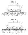
Fig. 1 is a cross-sectional view illustrating a contact member and a switch device according to an embodiment of the invention, in whichFig. 1A illustrates a non-contact state, andFig. 1B illustrates a contact state. -
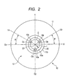
Fig. 2 is a plan view of the contact member according to the embodiment of the invention. -
Fig. 3 is a plan view illustrating a hoop material for forming the contact member. -
Figs. 4A and 4B are explanatory views of an operating sensation when the center of a curved portion of the contact member is pressed by a stem. -
Figs. 5A and 5B are explanatory views of an operating sensation when a position deviated from the center of the curved portion of the contact member is pressed by the stem. -
Fig. 6 is a plan view illustrating a contact member according to a comparative example. -
Fig. 7A is an explanatory view illustrating a distribution of elastic reaction when the contact member according to the embodiment is used, andFig. 7B is an explanatory view illustrating a distribution of elastic reaction when the contact member according to the comparative example is used. -
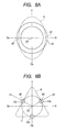
Figs. 8A and 8B are explanatory views for explaining characteristics of the elastic reaction of the contact member according to the embodiment. -
Figs. 9A and 9B are explanatory views for explaining characteristics of the elastic reaction of the contact member according to the comparative example. -
Fig. 10 is a plan view illustrating a contact member according to another embodiment of the invention. - A plurality of switch devices 1 are arranged to be lined up on a
substrate 2, and only the single switch device 1 is illustrated inFig. 1 . - On a
surface 2a of thesubstrate 2, an outside fixedcontact 3 and a center fixedcontact 4 are formed of a low-resistance conductive material such as gold or silver. Acontact member 10 has afirst side 10a and asecond side 10b, and thefirst side 10a is fixed to aflexible sheet 5. Theflexible sheet 5 is a synthetic resin sheet with insulating properties, and on arear surface 5a thereof, an adhesive layer is formed, such that thecontact member 10 is fixed to therear surface 5a of theflexible sheet 5 by the adhesive layer. In a part where thecontact member 10 is not provided, therear surface 5a of theflexible sheet 5 is fixed to the surface2a of thesubstrate 2 via the adhesive layer. - As illustrated in
Fig. 2 , the outerperipheral edge 11 of thecontact member 10 is circular, and in the switch device 1 illustrated inFig. 1 , the outerperipheral edge 11 comes in contact with the outside fixedcontact 3. In thecontact member 10, substantially the entire region of the inside of the outerperipheral edge 11 is acurved portion 12, and thecurved portion 12 is formed in a dome shape so that the convex side thereof faces thefirst side 10a. When thecurved portion 12 is pressed against thesubstrate 2, as illustrated inFig. 1B , thecontact member 10 is inverted and is elastically deformed. - The
contact member 10 is formed of a leaf spring material made of a rolled stainless steel. The rolling direction of the leaf spring material is the X direction illustrated inFig. 2 . InFig. 2 , the vertical center line extending in the X direction parallel to the rolling direction through the center (center of gravity: centroid) O1 of thecurved portion 12 is represented by Ox. In addition, the horizontal center line extending in the Y direction orthogonal to the rolling direction through the center O1 is represented by Oy. - The
contact member 10 illustrated inFigs. 1 and2 is cut from ahoop material 20 illustrated inFig. 3 . In general, regarding thehoop material 20, the rolling direction of the stainless steel is directed to the longitudinal direction (the X direction). Thehoop material 20 has feedingholes 23 provided at a predetermined pitch and is intermittently sent in the X direction while the feeding holes 23 are held by a traverse apparatus. Semicircular arc holes 21 are opened by a press apparatus, and inside the semicircular arc holes 21 and 21 which oppose each other, thecontact member 10 is connected byconnection pieces curved portion 12 and the like are press-formed, theconnection pieces individual contact members 10 are separated from thehoop material 20. The rolling direction of thecontact members 10 cut from thehoop material 20 is the X direction. - On the
curved portion 12 of thecontact member 10, threeprotrusions rear surface 12a thereof toward thesecond side 10b (a direction to the substrate 2). Theprotrusions hoop material 20 illustrated inFig. 3 . - In
Fig. 2 , although theprotrusions protrusions second side 10b (thesubstrate 2 side) are illustrated by being seen through thefirst side 10a. That is, the contours of the circles illustrated inFig. 2 are boundary lines between theprotrusions rear surface 12a of thecurved portion 12. - As illustrated in
Fig. 2 , when a virtual circle C with a predetermined radius r from the center O1 of thecurved portion 12 of thecontact member 10 is drawn, the center point Oa of theprotrusion 13a, the center point Ob of theprotrusion 13b, and the center point Oc of theprotrusion 13c are positioned on the virtual circle C. That is, the center points Oa, Ob, and Oc thereof are positioned at positions of equal distances r from the center O1 of thecurved portion 12. The radius r is equal to or smaller than 0.5 mm and is, for example, 0.3 mm. The center points Oa, Ob, and Oc of theprotrusions curved portion 12, and the disposition angle intervals of the center points Oa, Ob, and OC are 120 degrees. - Regarding all the
protrusions second side 10b) thereof are distant from the vertical center line Ox extending in the rolling direction of the metal plate. In the embodiment illustrated inFig. 2 , theprotrusions protrusions protrusion 13a is positioned on the horizontal center line Oy, an angle θ between a virtual line Lb connecting the center point Ob of theprotrusion 13b and the center O1 and the vertical center line Ox is 30 degrees, and an angle θ between a virtual line Lc connecting the center point Oc of theprotrusion 13c and the center O1 and the vertical center line Ox is 30 degrees. - In the
curved portion 12 of thecontact member 10, a raisedportion 15 raised from asurface 12b toward thefirst side 10a is formed. The raisedportion 15 is processed by the press apparatus in the state of thehoop material 20 illustrated inFig. 3 . The raisedportion 15 is formed so as to be raised from thesurface 12b between an innerperipheral contour 15a and an outerperipheral contour 15b. Theinside contour 15a is positioned outside theprotrusions center 01. In the example illustrated inFig. 2 , the raisedportion 15 is formed in a 360-degree continuous ring shape. However, the raisedportion 15 may be formed in an intermittent ring shape which is separated at each of the predetermined angles. - The radius of the outer
peripheral contour 15b of the raisedportion 15 from the center O1 is in a range of 0.5 to 1.0 mm, and is, for example, 0.75 mm. - As illustrated in
Fig. 1 , in the switch device 1, an operatingbody 8 is provided. Theoperation body 8 is provided so as to be elevated in the case of an electronic device and is pressed and operated as an operatingportion 8a is pressed by a finger. Astem 8b is provided at the lower portion of the operatingbody 8, and thestem 8b opposes the raisedportion 15 of thecontact member 10 via theflexible sheet 5. The lower surface of thestem 8b is circular, and the diameter thereof is slightly greater than the diameter of the outerperipheral contour 15b of the raisedportion 15. - In the switch device 1, as illustrated in
Fig. 1B , when the operatingbody 8 is pressed, the raisedportion 15 of thecontact member 10 is pressed down by thestem 8b via theflexible sheet 5. When the raisedportion 15 is pressed, thecurved portion 12 is elastically deformed toward thesubstrate 2. When thecurved portion 12 is deformed halfway, thecurved portion 12 is inverted toward thesubstrate 2, and theprotrusions contact 4, so that the outside fixedcontact 3 and the center fixedcontact 4 are electrically connected to each other with thecontact member 10. As illustrated inFig. 1B , at a time point when theprotrusions contact 4, thecurved portion 12 has an elastic restoring force in a direction away from thesubstrate 2. Therefore, when the pressing force against the operatingbody 8 is released, thecontact member 10 is returned to a non-contact state illustrated inFig. 1A . - Since the ring-shaped raised
portion 15 is formed in thecontact member 10 and the raisedportion 15 is pressed by thestem 8b, unnecessary deformation is less likely to occur at the center portion of thecontact member 10, and thus the center portion thereof having the raisedportion 15 and theprotrusions substrate 2 in a stable posture. Since theprotrusions contact 4 in small areas, reliability of contact is enhanced. In addition, even though an insulating material such as dust is present on the surface of the center fixedcontact 4, when theprotrusions contact 4, the insulating material is removed, so that reliability of electrical connection between thecontact member 10 and the center fixedcontact 4 is enhanced. -
Fig. 4A illustrates an operation when thecurved portion 12 is pressed while the center of thestem 8b is aligned with the center O1 of thecurved portion 12, andFig. 4B illustrates a change in elastic reaction imparted to theoperating body 8 from thecontact member 10 at this time. - The horizontal axis of
Fig. 4B represents a pressing stroke (a displacement of the curved portion 12) of the operatingbody 8, and the vertical axis thereof represents a load needed to deform thecurved portion 12, that is, a reaction exerted on theoperating body 8. When thecurved portion 12 is pressed by the operatingbody 8, the reaction is gradually increased and reaches the maximum value W1, thecurved portion 12 is thereafter inverted toward thesubstrate 2, and the reaction becomes the minimum value W2. Thereafter, when the pressing force against the operatingbody 8 is released, thecurved portion 12 is returned to its base curved state. -
Fig. 5A illustrates an operation when thecurved portion 12 is pressed while the center of thestem 8b is deviated from the center O1 of thecurved portion 12, andFig. 5B illustrates a change in elastic reaction exerted on theoperating body 8 at this time. W3 denotes the maximum value of the load, and W4 denotes the minimum value. - In
Fig. 4B , a difference ΔW1 between the maximum value W1 and the minimum value W2 of the reaction is high, and the value of ΔW1/W1 is increased. This means that the operating sensation (a so-called clicking sensation) in the finger pressing theoperating body 8 is good. Conversely, inFig. 5B , a difference ΔW2 between the maximum value W3 and the minimum value W4 of the reaction is relatively small, and the value of ΔW2/W3 is smaller than that ofFig. 4 . This means that the operating sensation (the so-called clicking sensation) in the finger pressing theoperating body 8 is slightly deteriorated compared to that ofFig. 4 . - As illustrated in
Figs. 1 and2 , the ring-shaped raisedportion 15 is formed in thecurved portion 12, and the raisedportion 15 is pressed by thestem 8b. When the raisedportion 15 is pressed by thestem 8b, the entirety of the ring-shaped raisedportion 15 of which the rigidity is increased is more likely to move toward thesubstrate 2. Therefore, even though the center of thestem 8b is deviated from the center O1 of thecurved portion 12, a structure in which extreme deterioration of the operating sensation is less likely to occur. However, the part thereof where theprotrusions curved portion 12 to be inverted. Therefore, as illustrated inFigs. 5A and 5B , it is difficult to avoid degradation of a contact sensation. - Here, in the
contact member 10 of this embodiment, the threeprotrusions curved portion 12 is exerted while being deviated from the center O1 in any direction, excessive degradation of the operating sensation is less likely to occur. -
Fig. 7A shows simulation results of calculation of ΔW2/W3 ofFig. 5B by moving the center of thestem 8b from thecenter 01 of thecurved portion 12 by a distance of 0.1 mm so as to be distant in both the X and Y directions. During the simulation, the diameter of the virtual circle C on which theprotrusions peripheral contour 15b of the raisedportion 15 was set to 1.5 mm, and the diameter of thestem 8b was set to 1.7 mm. - α shown in
Fig. 7A represents an area where ΔW2/W3×100 is equal to or greater than 45% when thecurved portion 12 is pressed while the center of thestem 8b is placed in the area, β represents an area where ΔW2/W3×100 is less than 45% when thecurved portion 12 is pressed while the center of thestem 8b is placed in the area. γ represents an area where ΔW2/W3×100 is less than 35%. -
Fig. 6 illustrates acontact member 110 of a comparative example. The shape and the diameter of an outerperipheral edge 11 of thecontact member 110 and the curvature of acurved portion 12 are the same as those of thecontact member 10 of the embodiment. The shape and the size of a raisedportion 15 of thecontact member 110 are also the same as those of thecontact member 10. -
Protrusions contact member 110 toward asecond side 10b. The shapes of theprotrusions substrate 2 side are the same as those of theprotrusions contact member 10. The radius r of a virtual circle C where the center points Od, Oe, and Of theprotrusions contact member 10. - In the
contact member 110 of this example, the center point Od of theprotrusion 13d is positioned on the vertical center line Ox extending in the rolling direction of a metal plate. A virtual line Le in which the center point Oe of theprotrusion 13e is positioned has an angle of θ=30 degrees from the horizontal center line Oy, and a virtual line Lf in which the center point Of of theprotrusion 13f is positioned has an angle of θ=30 degrees from the horizontal center line Oy. - In the comparative example illustrated in
Fig. 6 , a change in the operating sensation when the center of astem 8b with a diameter of 1.7 mm is pressed against thecurved portion 12 while being displaced from the center O1 of thecurved portion 12 in the X and Y directions, is shown inFig. 7B . α, β, and y ofFig. 7B represent areas where ΔW2/W3×100 determined when the center of astem 8b is placed in the areas is equal to or greater than 45%, less than 45%, and less than 35%, respectively, as inFig. 7A . - As illustrated in
Fig. 7A , when thecontact member 10 of this embodiment is used, even when the center of thestem 8b is pressed at a position displaced from thecenter 01 of thecurved portion 12 in each of the X and Y directions, the ratio of ΔW2/W3 is not significantly reduced, and a good operating sensation may be obtained. Particularly, even when the center of thestem 8b is displaced to the position of the virtual circle C or a position slightly on the outside, extreme deterioration of the operating sensation is less likely to occur. - As illustrated in
Fig. 7B , in the case where thecontact member 110 of the comparative example is used, when the center of thestem 8b is pressed against thecurved portion 12 while being placed in the vicinity of theprotrusion 13d, it can be seen that ΔW2/W3×100 becomes less than 45% and thus the operating sensation is extremely degraded. - In the
contact member 10 of this embodiment illustrated inFig. 2 , since the contours (the contours viewed from thesubstrate 2 side) of all theprotrusions stem 8b is deviated to the vicinities of theprotrusions protrusion 13a is positioned on the horizontal center line Oy, the contours of the other twoprotrusions curved portion 12 is pressed in the vicinities of theprotrusions - Conversely, the
contact member 110 of the comparative example illustrated inFig. 6 , theprotrusion 13d is positioned immediately on the vertical center line Ox. Therefore, when the center of thestem 8b is positioned in the vicinity of theprotrusion 13d and thecurved portion 12 is pressed, the operating sensation in this part is locally deteriorated. -
Figs. 8 and9 are explanatory views for explaining the reason.
Fig. 8A is a diagram for explaining the operating sensation of thecurved portion 12 where theprotrusions portion 15 is provided. - Since the rolling direction of the metal leaf spring material from which the
contact member 10 is made is the X direction, bending rigidity and bending elastic modulus when the leaf spring material is bent in the X direction (bent around the axis extending in the Y direction) are low, and compared to this, bending rigidity and bending elastic modulus when the leaf spring material is bent in the Y direction (bent around the axis extending in the X direction) are increased. - The inversing operation of the
curved portion 12 being pressed is influenced by the bending rigidity and the bending elastic modulus in a direction along the line connecting the pressing point and thecenter 01. As the bending rigidity and the bending elastic modulus in the direction along the line connecting the pressing point and the center O1 are increased, the center O1 of thecurved portion 12 is more likely to be inversed toward thesubstrate 2, the difference between the maximum value W3 and the minimum value W4 of the reaction is increased, and thus the operating sensation (the so-called clicking sensation) is enhanced. - As illustrated in
Fig. 8A , when the rolling direction of the leaf spring material is the X direction, an area A where the operating sensation is not significantly changed when the pressing point is displaced from the center O1 is short in the X direction and is lengthened in the Y direction. As shown by reference numeral A1, on the vertical center line Ox, an area where the operating sensation is deteriorated when the pressing point is displaced approaches the center O1. - In addition, anisotropy of the operating sensation caused by the rolling direction illustrated in
Fig. 8A is also the same in a contact member where the raisedportion 15 is not provided. -
Fig. 8B is a diagram for explaining the relationship between the arrangement direction of theprotrusions curved portion 12 and the operating sensation. - The parts where the
protrusions curved portion 12 is set to the vicinities of theprotrusions curved portion 12 is less likely to be elastically deformed, and the ratio of ΔW2/W3 when thecurved portion 12 is inverted is reduced. Conversely, an area between theadjacent protrusions center 01. This is similar to an area between theadjacent protrusions protrusions - As illustrated in
Fig. 8B , focusing on the influence of theprotrusions curved portion 12 is pressed while the position thereof is displaced from the center O1, an area B where the operating sensation is high and is not deteriorated becomes a substantially triangular area. - In the
contact member 10 of this embodiment, since the contours of theprotrusions Fig. 8B , a part B1 (the center portion of the side of the triangular area B) in the area B where the operating sensation is more likely to be degraded is distant from a part A1 where the operating sensation is more likely to be degraded due to the rolling direction illustrated inFig. 8B . As a result, as illustrated inFig. 7A , in a wide range from the center O1 in each of the X and Y directions, even though the center of thestem 8b is deviated, deterioration of the operating sensation is less likely to occur. - Conversely, as in the
contact member 110 of the comparative example, when theprotrusion 13d is disposed on the vertical center line Ox, as illustrated inFig. 9B , the direction of a triangular area E where the operating sensation is high and is not deteriorated becomes different from that ofFig. 8B . As illustrated inFig. 9B , the periphery of theprotrusion 13d positioned on the vertical center line Ox is a part E1 where the operating sensation is degraded when the position of the periphery is pressed. As illustrated inFig. 9A , since the part E1 overlaps with the part A1 where the operating sensation is degraded due to the extension direction of the metal plate, as illustrated inFig. 7B , the operating sensation of the periphery of theprotrusion 13d when thecurved portion 12 is pressed at the position of the periphery is locally degraded. -
Fig. 10 illustrates acontact member 30 of another embodiment of the invention.
In thecontact member 30, the shape and the size of a raisedportion 15 formed in acurved portion 12 are the same as those of thecontact member 10 illustrated inFigs. 1 and2 .Protrusions contact member 10. Opening angles between virtual lines Lg, Lh, and Li passing through the center O1 and the center points of the respective protrusions are 120 degrees. - In
Fig. 10 , an angle θ1 between the virtual line Lg and the vertical center line Ox is less than 30 degrees, and an angle θ2 between the virtual line Lh and the vertical center line Ox exceeds 30 degrees. Therefore, theprotrusion 13g approaches the vertical center line Ox. However, the circular contour of theprotrusion 13g viewed from thesubstrate 2 side is distant from the vertical center line Ox. Therefore, the part E1 where the operating sensation is deteriorated due to the presence of the protrusion illustrated inFigs. 9A and 9B may be prevented from overlapping with or approaching the part A1 where the operating sensation is deteriorated due to the influence of the extension direction. Therefore, unlike thecontact member 110 of the comparative example, an area where the operating contact is deteriorated may be prevented from being locally generated. - In addition, the invention is not limited to the embodiments. For example, the number of protrusions may be equal to or greater than 4, and the contours of the individual protrusions viewed from the substrate side may not be circular.
-
- 1
- switch device
- 2
- substrate
- 3
- outside fixed contact
- 4
- center fixed contact
- 5
- flexible sheet
- 8
- operating body
- 8b
- stem
- 10
- contact member
- 10a
- first side
- 10b
- second side
- 12
- curved portion
- 13a, 13b, 13c
- protrusion
- 15
- raised portion
- 20
- hoop material
- O1
- center of curved portion
- Ox
- vertical center line
- Oy
- horizontal center line
Claims (15)
- A contact member, comprising:a curved portion which is formed of a rolled conductive metal plate and protrudes toward a first side, the curved portion being elastically deformable toward a second side; anda plurality of protrusions formed to protrude toward the second side from the curved portion,wherein all the protrusions are formed at positions that do not overlap with a vertical center line extending in parallel to a rolling direction through a center of the curved portion.
- The contact member according to claim 1, wherein contours of all the protrusions when viewed from the second side are positioned to be distant from the center line.
- The contact member according to claim 1, wherein the protrusions are positioned at equal distances from the center of the curved portion.
- The contact member according to claim 2, wherein the protrusions are positioned at equal distances from the center of the curved portion.
- The contact member according to claim 3, wherein center points of the plurality of protrusions are disposed at equal angles with respect to the center of the curved portion.
- The contact member according to claim 4, wherein center points of the plurality of protrusions are disposed at equal angles with respect to the center of the curved portion.
- The contact member according to claim 5, wherein the number of the protrusions is 3, and a center point of one of the protrusions is positioned on a horizontal center line orthogonal to the vertical center line through the center of the curved portion.
- The contact member according to claim 6, wherein the number of the protrusions is 3, and a center point of one of the protrusions is positioned on a horizontal center line orthogonal to the vertical center line through the center of the curved portion.
- The contact member according to any one of claims 1 to 8, further comprising a raised portion formed to protrude toward the first side from the curved portion,
wherein the raised portion is provided at a position farther from the center of the curved portion than the protrusions, and
the raised portion is formed continuously or intermittently along an arc with a predetermined radius from the center. - The contact member according to any one of claims 1 to 8, wherein the first side of a plurality of the metal plates having the curved portion is fixed to a flexible synthetic resin sheet.
- The contact member according to claim 9, wherein the first side of a plurality of the metal plates having the curved portion is fixed to a flexible synthetic resin sheet.
- A switch device comprising:a substrate having a plurality of fixed contacts on a surface,the contact member according to any one of claims 1 to 8 of which the second side is installed so as to face the surface of the substrate,wherein a peripheral part of the curved portion of the metal plate comes in contact with any of the fixed contacts, andthe protrusions oppose the other fixed contacts.
- A switch device comprising:a substrate having a plurality of fixed contacts on a surface,the contact member according to claim 9 of which the second side is installed so as to face the surface of the substrate,wherein a peripheral part of the curved portion of the metal plate comes in contact with any of the fixed contacts, andthe protrusions oppose the other fixed contacts.
- A switch device comprising:a substrate having a plurality of fixed contacts on a surface,the contact member according to claim 10 of which the second side is installed so as to face the surface of the substrate,wherein a peripheral part of the curved portion of the metal plate comes in contact with any of the fixed contacts, andthe protrusions oppose the other fixed contacts.
- A switch device comprising:a substrate having a plurality of fixed contacts on a surface,the contact member according to claim 11 of which the second side is installed so as to face the surface of the substrate,wherein a peripheral part of the curved portion of the metal plate comes in contact with any of the fixed contacts, andthe protrusions oppose the other fixed contacts.
Applications Claiming Priority (2)
| Application Number | Priority Date | Filing Date | Title |
|---|---|---|---|
| JP2010103635 | 2010-04-28 | ||
| PCT/JP2011/058975 WO2011136006A1 (en) | 2010-04-28 | 2011-04-11 | Contact member and switch device using contact member |
Publications (3)
| Publication Number | Publication Date |
|---|---|
| EP2565888A1 true EP2565888A1 (en) | 2013-03-06 |
| EP2565888A4 EP2565888A4 (en) | 2014-12-03 |
| EP2565888B1 EP2565888B1 (en) | 2019-01-09 |
Family
ID=44861318
Family Applications (1)
| Application Number | Title | Priority Date | Filing Date |
|---|---|---|---|
| EP11774790.7A Active EP2565888B1 (en) | 2010-04-28 | 2011-04-11 | Contact member and switch device using contact member |
Country Status (2)
| Country | Link |
|---|---|
| EP (1) | EP2565888B1 (en) |
| WO (1) | WO2011136006A1 (en) |
Family Cites Families (12)
| Publication number | Priority date | Publication date | Assignee | Title |
|---|---|---|---|---|
| JPH0594919U (en) * | 1992-05-29 | 1993-12-24 | ミツミ電機株式会社 | Push switch |
| JPH0727033U (en) * | 1993-10-21 | 1995-05-19 | 帝国通信工業株式会社 | Movable contact piece or click plate |
| JP2001286905A (en) * | 2000-04-11 | 2001-10-16 | Toyo Seihaku Kk | Stainless steel foil |
| JP2003077366A (en) * | 2001-09-05 | 2003-03-14 | Seiko Precision Inc | Switching unit |
| JP2004139997A (en) * | 2003-12-19 | 2004-05-13 | Alps Electric Co Ltd | Push-button switch |
| JP4493511B2 (en) * | 2005-02-02 | 2010-06-30 | アルプス電気株式会社 | Movable contact, seat with movable contact and switch device using the same |
| JP2007134152A (en) * | 2005-11-10 | 2007-05-31 | Matsushita Electric Ind Co Ltd | Movable contact and movable contact body and switch constructed using the same |
| JP2007173099A (en) * | 2005-12-22 | 2007-07-05 | Alps Electric Co Ltd | Switching device |
| JP4653004B2 (en) | 2006-04-10 | 2011-03-16 | アルプス電気株式会社 | Manufacturing method of reversing leaf spring for switch |
| GB2444092B (en) * | 2006-11-21 | 2009-04-29 | Motorola Inc | Electronic device, keypad and switch mechanism |
| JP2009037892A (en) * | 2007-08-02 | 2009-02-19 | Panasonic Corp | Movable contact |
| JP2009152119A (en) * | 2007-12-21 | 2009-07-09 | Alps Electric Co Ltd | Reverse spring for switch, and switch device which has reverse spring for switch |
-
2011
- 2011-04-11 WO PCT/JP2011/058975 patent/WO2011136006A1/en not_active Ceased
- 2011-04-11 EP EP11774790.7A patent/EP2565888B1/en active Active
Also Published As
| Publication number | Publication date |
|---|---|
| EP2565888B1 (en) | 2019-01-09 |
| WO2011136006A1 (en) | 2011-11-03 |
| EP2565888A4 (en) | 2014-12-03 |
Similar Documents
| Publication | Publication Date | Title |
|---|---|---|
| US10008801B2 (en) | Pressure contact type connector and manufacturing method of the same | |
| US7301113B2 (en) | Diaphragm for use in switch, method for manufacturing thereof, membrane switch, and input device | |
| CN100490036C (en) | Switch for inputting signal | |
| EP2875516B1 (en) | Push button switch having a curved deformable contact element | |
| US20100012473A1 (en) | Metal Domed Contact Component and Card Comprising It | |
| CN106910658B (en) | Key switch and movable contact member | |
| EP2565888B1 (en) | Contact member and switch device using contact member | |
| KR100570864B1 (en) | Contact spring | |
| US9570827B2 (en) | Contact member | |
| US20160268066A1 (en) | Dome-shaped movable contact piece | |
| US20140054155A1 (en) | Long-stroke dome-shaped movable contact piece | |
| US7525060B2 (en) | Movable contact point | |
| US8957339B2 (en) | Dome-shaped spring and switch using the same | |
| JP6080702B2 (en) | Push switch | |
| US20120145526A1 (en) | Movable contact for switching | |
| US7560655B2 (en) | Movable contact and push switch using the same | |
| KR200478714Y1 (en) | Tact Switch | |
| JPWO2018020754A1 (en) | Switch body | |
| CN101840802B (en) | Movable contact for switch, and switch device | |
| TWI690964B (en) | power switch button | |
| JP7182039B2 (en) | A movable contact, a switch with a movable contact, and an embossed tape containing the movable contact | |
| KR102245541B1 (en) | Spring member and switch | |
| JP2005026129A (en) | Contact spring for switch | |
| JP2005302454A (en) | Press switch and its movable contact | |
| JP2006012678A (en) | Press switch and its movable contact |
Legal Events
| Date | Code | Title | Description |
|---|---|---|---|
| PUAI | Public reference made under article 153(3) epc to a published international application that has entered the european phase |
Free format text: ORIGINAL CODE: 0009012 |
|
| 17P | Request for examination filed |
Effective date: 20120305 |
|
| AK | Designated contracting states |
Kind code of ref document: A1 Designated state(s): AL AT BE BG CH CY CZ DE DK EE ES FI FR GB GR HR HU IE IS IT LI LT LU LV MC MK MT NL NO PL PT RO RS SE SI SK SM TR |
|
| DAX | Request for extension of the european patent (deleted) | ||
| A4 | Supplementary search report drawn up and despatched |
Effective date: 20141030 |
|
| RIC1 | Information provided on ipc code assigned before grant |
Ipc: H01H 13/85 20060101ALI20141024BHEP Ipc: H01H 1/06 20060101AFI20141024BHEP Ipc: H01H 13/48 20060101ALI20141024BHEP Ipc: H01H 11/00 20060101ALI20141024BHEP Ipc: H01H 5/30 20060101ALI20141024BHEP Ipc: H01H 13/702 20060101ALI20141024BHEP |
|
| 17Q | First examination report despatched |
Effective date: 20161004 |
|
| STAA | Information on the status of an ep patent application or granted ep patent |
Free format text: STATUS: EXAMINATION IS IN PROGRESS |
|
| GRAP | Despatch of communication of intention to grant a patent |
Free format text: ORIGINAL CODE: EPIDOSNIGR1 |
|
| STAA | Information on the status of an ep patent application or granted ep patent |
Free format text: STATUS: GRANT OF PATENT IS INTENDED |
|
| INTG | Intention to grant announced |
Effective date: 20180726 |
|
| GRAS | Grant fee paid |
Free format text: ORIGINAL CODE: EPIDOSNIGR3 |
|
| GRAA | (expected) grant |
Free format text: ORIGINAL CODE: 0009210 |
|
| STAA | Information on the status of an ep patent application or granted ep patent |
Free format text: STATUS: THE PATENT HAS BEEN GRANTED |
|
| AK | Designated contracting states |
Kind code of ref document: B1 Designated state(s): AL AT BE BG CH CY CZ DE DK EE ES FI FR GB GR HR HU IE IS IT LI LT LU LV MC MK MT NL NO PL PT RO RS SE SI SK SM TR |
|
| REG | Reference to a national code |
Ref country code: GB Ref legal event code: FG4D |
|
| REG | Reference to a national code |
Ref country code: CH Ref legal event code: EP Ref country code: AT Ref legal event code: REF Ref document number: 1088347 Country of ref document: AT Kind code of ref document: T Effective date: 20190115 |
|
| REG | Reference to a national code |
Ref country code: DE Ref legal event code: R096 Ref document number: 602011055585 Country of ref document: DE |
|
| REG | Reference to a national code |
Ref country code: IE Ref legal event code: FG4D |
|
| REG | Reference to a national code |
Ref country code: DE Ref legal event code: R081 Ref document number: 602011055585 Country of ref document: DE Owner name: ALPS ALPINE CO., LTD., JP Free format text: FORMER OWNER: ALPS ELECTRIC CO., LTD., TOKYO, JP |
|
| REG | Reference to a national code |
Ref country code: NL Ref legal event code: MP Effective date: 20190109 |
|
| REG | Reference to a national code |
Ref country code: LT Ref legal event code: MG4D |
|
| PG25 | Lapsed in a contracting state [announced via postgrant information from national office to epo] |
Ref country code: NL Free format text: LAPSE BECAUSE OF FAILURE TO SUBMIT A TRANSLATION OF THE DESCRIPTION OR TO PAY THE FEE WITHIN THE PRESCRIBED TIME-LIMIT Effective date: 20190109 |
|
| REG | Reference to a national code |
Ref country code: AT Ref legal event code: MK05 Ref document number: 1088347 Country of ref document: AT Kind code of ref document: T Effective date: 20190109 |
|
| PG25 | Lapsed in a contracting state [announced via postgrant information from national office to epo] |
Ref country code: PL Free format text: LAPSE BECAUSE OF FAILURE TO SUBMIT A TRANSLATION OF THE DESCRIPTION OR TO PAY THE FEE WITHIN THE PRESCRIBED TIME-LIMIT Effective date: 20190109 Ref country code: ES Free format text: LAPSE BECAUSE OF FAILURE TO SUBMIT A TRANSLATION OF THE DESCRIPTION OR TO PAY THE FEE WITHIN THE PRESCRIBED TIME-LIMIT Effective date: 20190109 Ref country code: LT Free format text: LAPSE BECAUSE OF FAILURE TO SUBMIT A TRANSLATION OF THE DESCRIPTION OR TO PAY THE FEE WITHIN THE PRESCRIBED TIME-LIMIT Effective date: 20190109 Ref country code: FI Free format text: LAPSE BECAUSE OF FAILURE TO SUBMIT A TRANSLATION OF THE DESCRIPTION OR TO PAY THE FEE WITHIN THE PRESCRIBED TIME-LIMIT Effective date: 20190109 Ref country code: PT Free format text: LAPSE BECAUSE OF FAILURE TO SUBMIT A TRANSLATION OF THE DESCRIPTION OR TO PAY THE FEE WITHIN THE PRESCRIBED TIME-LIMIT Effective date: 20190509 Ref country code: NO Free format text: LAPSE BECAUSE OF FAILURE TO SUBMIT A TRANSLATION OF THE DESCRIPTION OR TO PAY THE FEE WITHIN THE PRESCRIBED TIME-LIMIT Effective date: 20190409 Ref country code: SE Free format text: LAPSE BECAUSE OF FAILURE TO SUBMIT A TRANSLATION OF THE DESCRIPTION OR TO PAY THE FEE WITHIN THE PRESCRIBED TIME-LIMIT Effective date: 20190109 |
|
| PG25 | Lapsed in a contracting state [announced via postgrant information from national office to epo] |
Ref country code: GR Free format text: LAPSE BECAUSE OF FAILURE TO SUBMIT A TRANSLATION OF THE DESCRIPTION OR TO PAY THE FEE WITHIN THE PRESCRIBED TIME-LIMIT Effective date: 20190410 Ref country code: BG Free format text: LAPSE BECAUSE OF FAILURE TO SUBMIT A TRANSLATION OF THE DESCRIPTION OR TO PAY THE FEE WITHIN THE PRESCRIBED TIME-LIMIT Effective date: 20190409 Ref country code: LV Free format text: LAPSE BECAUSE OF FAILURE TO SUBMIT A TRANSLATION OF THE DESCRIPTION OR TO PAY THE FEE WITHIN THE PRESCRIBED TIME-LIMIT Effective date: 20190109 Ref country code: IS Free format text: LAPSE BECAUSE OF FAILURE TO SUBMIT A TRANSLATION OF THE DESCRIPTION OR TO PAY THE FEE WITHIN THE PRESCRIBED TIME-LIMIT Effective date: 20190509 Ref country code: RS Free format text: LAPSE BECAUSE OF FAILURE TO SUBMIT A TRANSLATION OF THE DESCRIPTION OR TO PAY THE FEE WITHIN THE PRESCRIBED TIME-LIMIT Effective date: 20190109 Ref country code: HR Free format text: LAPSE BECAUSE OF FAILURE TO SUBMIT A TRANSLATION OF THE DESCRIPTION OR TO PAY THE FEE WITHIN THE PRESCRIBED TIME-LIMIT Effective date: 20190109 |
|
| REG | Reference to a national code |
Ref country code: DE Ref legal event code: R097 Ref document number: 602011055585 Country of ref document: DE |
|
| PG25 | Lapsed in a contracting state [announced via postgrant information from national office to epo] |
Ref country code: AL Free format text: LAPSE BECAUSE OF FAILURE TO SUBMIT A TRANSLATION OF THE DESCRIPTION OR TO PAY THE FEE WITHIN THE PRESCRIBED TIME-LIMIT Effective date: 20190109 Ref country code: CZ Free format text: LAPSE BECAUSE OF FAILURE TO SUBMIT A TRANSLATION OF THE DESCRIPTION OR TO PAY THE FEE WITHIN THE PRESCRIBED TIME-LIMIT Effective date: 20190109 Ref country code: SK Free format text: LAPSE BECAUSE OF FAILURE TO SUBMIT A TRANSLATION OF THE DESCRIPTION OR TO PAY THE FEE WITHIN THE PRESCRIBED TIME-LIMIT Effective date: 20190109 Ref country code: AT Free format text: LAPSE BECAUSE OF FAILURE TO SUBMIT A TRANSLATION OF THE DESCRIPTION OR TO PAY THE FEE WITHIN THE PRESCRIBED TIME-LIMIT Effective date: 20190109 Ref country code: IT Free format text: LAPSE BECAUSE OF FAILURE TO SUBMIT A TRANSLATION OF THE DESCRIPTION OR TO PAY THE FEE WITHIN THE PRESCRIBED TIME-LIMIT Effective date: 20190109 Ref country code: RO Free format text: LAPSE BECAUSE OF FAILURE TO SUBMIT A TRANSLATION OF THE DESCRIPTION OR TO PAY THE FEE WITHIN THE PRESCRIBED TIME-LIMIT Effective date: 20190109 Ref country code: DK Free format text: LAPSE BECAUSE OF FAILURE TO SUBMIT A TRANSLATION OF THE DESCRIPTION OR TO PAY THE FEE WITHIN THE PRESCRIBED TIME-LIMIT Effective date: 20190109 Ref country code: EE Free format text: LAPSE BECAUSE OF FAILURE TO SUBMIT A TRANSLATION OF THE DESCRIPTION OR TO PAY THE FEE WITHIN THE PRESCRIBED TIME-LIMIT Effective date: 20190109 |
|
| PLBE | No opposition filed within time limit |
Free format text: ORIGINAL CODE: 0009261 |
|
| STAA | Information on the status of an ep patent application or granted ep patent |
Free format text: STATUS: NO OPPOSITION FILED WITHIN TIME LIMIT |
|
| PG25 | Lapsed in a contracting state [announced via postgrant information from national office to epo] |
Ref country code: SM Free format text: LAPSE BECAUSE OF FAILURE TO SUBMIT A TRANSLATION OF THE DESCRIPTION OR TO PAY THE FEE WITHIN THE PRESCRIBED TIME-LIMIT Effective date: 20190109 |
|
| REG | Reference to a national code |
Ref country code: CH Ref legal event code: PL |
|
| 26N | No opposition filed |
Effective date: 20191010 |
|
| REG | Reference to a national code |
Ref country code: BE Ref legal event code: MM Effective date: 20190430 |
|
| GBPC | Gb: european patent ceased through non-payment of renewal fee |
Effective date: 20190411 |
|
| PG25 | Lapsed in a contracting state [announced via postgrant information from national office to epo] |
Ref country code: MC Free format text: LAPSE BECAUSE OF FAILURE TO SUBMIT A TRANSLATION OF THE DESCRIPTION OR TO PAY THE FEE WITHIN THE PRESCRIBED TIME-LIMIT Effective date: 20190109 Ref country code: LU Free format text: LAPSE BECAUSE OF NON-PAYMENT OF DUE FEES Effective date: 20190411 |
|
| PG25 | Lapsed in a contracting state [announced via postgrant information from national office to epo] |
Ref country code: CH Free format text: LAPSE BECAUSE OF NON-PAYMENT OF DUE FEES Effective date: 20190430 Ref country code: LI Free format text: LAPSE BECAUSE OF NON-PAYMENT OF DUE FEES Effective date: 20190430 Ref country code: GB Free format text: LAPSE BECAUSE OF NON-PAYMENT OF DUE FEES Effective date: 20190411 |
|
| PG25 | Lapsed in a contracting state [announced via postgrant information from national office to epo] |
Ref country code: SI Free format text: LAPSE BECAUSE OF FAILURE TO SUBMIT A TRANSLATION OF THE DESCRIPTION OR TO PAY THE FEE WITHIN THE PRESCRIBED TIME-LIMIT Effective date: 20190109 Ref country code: FR Free format text: LAPSE BECAUSE OF NON-PAYMENT OF DUE FEES Effective date: 20190430 Ref country code: BE Free format text: LAPSE BECAUSE OF NON-PAYMENT OF DUE FEES Effective date: 20190430 |
|
| PG25 | Lapsed in a contracting state [announced via postgrant information from national office to epo] |
Ref country code: TR Free format text: LAPSE BECAUSE OF FAILURE TO SUBMIT A TRANSLATION OF THE DESCRIPTION OR TO PAY THE FEE WITHIN THE PRESCRIBED TIME-LIMIT Effective date: 20190109 |
|
| PG25 | Lapsed in a contracting state [announced via postgrant information from national office to epo] |
Ref country code: IE Free format text: LAPSE BECAUSE OF NON-PAYMENT OF DUE FEES Effective date: 20190411 |
|
| PG25 | Lapsed in a contracting state [announced via postgrant information from national office to epo] |
Ref country code: CY Free format text: LAPSE BECAUSE OF FAILURE TO SUBMIT A TRANSLATION OF THE DESCRIPTION OR TO PAY THE FEE WITHIN THE PRESCRIBED TIME-LIMIT Effective date: 20190109 |
|
| PG25 | Lapsed in a contracting state [announced via postgrant information from national office to epo] |
Ref country code: HU Free format text: LAPSE BECAUSE OF FAILURE TO SUBMIT A TRANSLATION OF THE DESCRIPTION OR TO PAY THE FEE WITHIN THE PRESCRIBED TIME-LIMIT; INVALID AB INITIO Effective date: 20110411 Ref country code: MT Free format text: LAPSE BECAUSE OF FAILURE TO SUBMIT A TRANSLATION OF THE DESCRIPTION OR TO PAY THE FEE WITHIN THE PRESCRIBED TIME-LIMIT Effective date: 20190109 |
|
| PG25 | Lapsed in a contracting state [announced via postgrant information from national office to epo] |
Ref country code: MK Free format text: LAPSE BECAUSE OF FAILURE TO SUBMIT A TRANSLATION OF THE DESCRIPTION OR TO PAY THE FEE WITHIN THE PRESCRIBED TIME-LIMIT Effective date: 20190109 |
|
| PGFP | Annual fee paid to national office [announced via postgrant information from national office to epo] |
Ref country code: DE Payment date: 20250422 Year of fee payment: 15 |