EP2565544B1 - Air conditioner - Google Patents
Air conditioner Download PDFInfo
- Publication number
- EP2565544B1 EP2565544B1 EP12157833.0A EP12157833A EP2565544B1 EP 2565544 B1 EP2565544 B1 EP 2565544B1 EP 12157833 A EP12157833 A EP 12157833A EP 2565544 B1 EP2565544 B1 EP 2565544B1
- Authority
- EP
- European Patent Office
- Prior art keywords
- cover
- base
- air conditioner
- unit
- electrical unit
- Prior art date
- Legal status (The legal status is an assumption and is not a legal conclusion. Google has not performed a legal analysis and makes no representation as to the accuracy of the status listed.)
- Active
Links
Images


Classifications
-
- F—MECHANICAL ENGINEERING; LIGHTING; HEATING; WEAPONS; BLASTING
- F24—HEATING; RANGES; VENTILATING
- F24F—AIR-CONDITIONING; AIR-HUMIDIFICATION; VENTILATION; USE OF AIR CURRENTS FOR SCREENING
- F24F1/00—Room units for air-conditioning, e.g. separate or self-contained units or units receiving primary air from a central station
- F24F1/0007—Indoor units, e.g. fan coil units
- F24F1/0087—Indoor units, e.g. fan coil units with humidification means
-
- F—MECHANICAL ENGINEERING; LIGHTING; HEATING; WEAPONS; BLASTING
- F24—HEATING; RANGES; VENTILATING
- F24F—AIR-CONDITIONING; AIR-HUMIDIFICATION; VENTILATION; USE OF AIR CURRENTS FOR SCREENING
- F24F13/00—Details common to, or for air-conditioning, air-humidification, ventilation or use of air currents for screening
- F24F13/20—Casings or covers
- F24F2013/207—Casings or covers with control knobs; Mounting controlling members or control units therein
Definitions
- the present invention relates to an arrangement of an electrical unit mounted in an indoor unit of an air conditioner.
- a conventional air conditioner includes an electrical unit accommodating electrical components therein and disposed on a front side of an indoor unit to increase the width of an indoor heat exchanger to thereby increase the amount of heat exchange (see, for example, Patent Document 1).
- Patent Document 1 Japanese Laid-Open Patent Publication No. 8-110085 EP2325572 discloses a n air conditioner upon which the preamble of appending claim 1 is based.
- the present invention has been developed to overcome the above-described disadvantage.
- the air conditioner according to the present invention includes an indoor unit, an indoor heat exchanger placed in the indoor unit and an electrical unit, wherein the electrical unit includes a base, a substrate mounted on the base and having electrical components placed thereon, and a cover for covering the base.
- the base has a groove portion defined therein so as to extend along an outer periphery thereof, the cover has a protrusion formed therewith so as to be fitted into the groove portion, and the electrical unit is placed in the indoor unit at a location delimited by a front face of the indoor heat exchanger, an upper suction opening, and a front suction opening.
- the air conditioner according to the present invention is effective in restraining impurities from entering the electrical unit.
- An air conditioner includes an indoor unit and an electrical unit accommodated in the indoor unit on a front side thereof, wherein the electrical unit includes a base, a substrate mounted on the base and having electrical components placed thereon, and a cover for covering the base.
- the base has a groove portion defined therein so as to extend along an outer periphery thereof, and the cover has a protrusion formed therewith so as to be fitted into the groove portion.
- a flame-retardant member is interposed between the base and the cover to enhance safety.
- the flame-retardant member be flexible to enhance the sealing performance between the base and the cover.
- the base includes an inner side wall and an outer side wall confronting each other, and the groove portion is formed therebetween, the inner side wall being higher than the outer side wall. This configuration further prevents impurities from entering the electrical unit.
- a sheet-metal cover for covering the cover be provided to prevent fire from spreading outside, thereby enhancing safety.
- An outer surface of the sheet-metal cover is preferably coated or painted to restrain a user from being injured by edges or burrs of the sheet-metal during maintenance, thus further enhancing safety.
- the cover preferably has a groove portion defined therein, in which an end portion of the sheet-metal cover is inserted.
- the groove portion acts to cover or conceal the edges of the sheet-metal cover, thereby further enhancing safety.
- Fig. 1 is a perspective view of an indoor unit of an air conditioner embodying the present invention.
- Fig. 2A is a front view of the indoor unit with a front panel installed
- Fig. 2B is a front view of the indoor unit with the front panel removed.
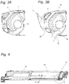
- Fig. 3A is a cross-sectional view taken along line A-A in Fig. 2A when the indoor unit is not in operation
- Fig. 3B is a cross-sectional view taken along line A-A in Fig. 2A when the indoor unit is in operation.
- the air conditioner in this embodiment includes an indoor unit 1 to be installed in a room and an outdoor unit (not shown) to be installed outside the room, both connected to each other via refrigerant piping and electric wires.
- FIG. 1 A construction of the indoor unit 1 is explained hereinafter with reference to Fig. 1, Figs. 2A and 2B , and Figs. 3A and 3B .
- the indoor unit 1 in this embodiment has an upper suction opening 2a defined in an upper wall thereof, through which indoor air is sucked from above, and a front suction opening 2b defined in a front wall thereof through which indoor air is sucked from front.
- the indoor unit 1 includes a front panel 2 for covering the front suction opening 2b from front. When the indoor unit 1 is brought into operation, the front panel 2 moves forward to open the front suction opening 2b, thereby increasing the amount of air sucked through the front suction opening 2b.
- the indoor unit 1 has a discharge opening 3 defined therein to blow out into a room air that has been sucked into the indoor unit 1.
- the indoor unit 1 also includes a plurality of vertical wind direction changing blades 3a and a plurality of horizontal wind direction changing blades 3 disposed in proximity to the discharge opening 3 to vertically and horizontally change the direction of air blown out through the discharge opening 3, respectively.
- the indoor unit 1 accommodates therein an indoor heat exchanger 5 generally in the form of an inverted V, an indoor fan 6 for conveying air sucked into the indoor unit 1 toward a room through the discharge opening 3, and an air filter 7 for collecting dust.
- the air filter 7 is held by a filter frame 7a, on which an automatic cleaning device for automatically cleaning the air filter 7 is mounted. Detailed explanation of the automatic cleaning device is omitted.
- Operation of the indoor fan 6 generates an air current, which in turn causes indoor air to be sucked into the indoor unit 1 through the upper suction opening 2a and the front suction opening 2b.
- the air sucked into the indoor unit 1 is heat exchanged with a refrigerant in the indoor heat exchanger 5 so that cold or warm air may be introduced into a room during cooling or heating.
- an electrical unit 8 is disposed at a location delimited by the upper suction opening 2a, the front suction opening 2b, and a front face of the indoor heat exchanger 5.
- This arrangement of the electrical unit 8 can make effective use of a dead space delimited by the upper suction opening 2a, the front suction opening 2b, and the front face of the indoor heat exchanger 5. Accordingly, it is not necessary to arrange the electrical unit 8 lateral to the indoor heat exchanger 5 and, hence, the width of the indoor heat exchanger 5 can be increased, thus making it possible to enhance the heat exchanging performance of the indoor heat exchanger 5.
- the electrical unit 8 includes a substrate, on which electrical components are placed, and accordingly generates heat, but the electrical unit 8 is cooled by a wind (indoor air) sucked through the upper suction opening 2a and front suction opening 2b. Further, because the electrical unit 8 is disposed above the indoor heat exchanger 5, drainage water generated in the indoor heat exchanger 5 is prevented from dripping on the electrical unit 8, thus making it possible to enhance the reliability.
- FIG. 4 is a perspective view of the electrical unit 8
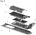
- Fig. 5 is an exploded perspective view of the electrical unit 8.
- Fig. 6 is an exploded perspective view depicting a positional relationship between the electrical unit 8 and the filter frame 7a.
- the electrical unit 8 includes a support plate 8a made by sheet-metal processing, a base 8b made of a flame-retardant resin, a substrate 8c on which electrical components are placed, a cover 8d made of a flame-retardant resin, and a metal cover 8e made by sheet-metal processing.
- An ABS resin and the like can be used for the flame-retardant resin to form the base 8b and the cover 8d.
- a terminal block 8f is separately disposed lateral to the electrical unit 8 and connected to electric wires that connect the electrical components on the substrate 8c and those accommodated in an outdoor unit (not shown).
- a connecting portion to which the electric wires are connected is positioned at the front to allow wiring or other work from a front side.
- the support plate 8a is disposed to support respective ends of the filter frame 7a. Because the support plate 8a is made by sheet-metal processing, it can prevent deformation of the electrical unit 8 that may be caused by an external force, for example, during transportation. Also, even if a worker applies an external force to the electrical unit 8 during maintenance, the shape of the support plate 8a acts to restrain a reduction in the distance between the electrical unit 8 and the filter frame 7a, thereby ensuring a predetermined amount of air to be sucked into the indoor unit 1. It is to be noted that the filter frame 7a and the support plate 8a may be connected to each other by screws or engaged with each other.
- the support plate 8a extends over an entire width (longitudinal direction) of the filter frame 7a.
- the substrate 8c is placed on a right side of the support plate 8a, and an opening or wind way 8g is formed on a left side of the support plate 8a so as not to impede an air current.
- the opening 8g acts to reduce a resistance to draft.
- the arrangement (positional relationship) of the substrate 8c and the opening 8g is not particularly limited, and it may be reversed horizontally or vertically.
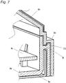
- Fig. 7 is a cross-sectional view taken along line B-B in Fig. 4 depicting the electrical unit 8
- Fig. 8 is an enlarged cross-sectional view of a mating portion between the base 8b and the cover 8d.
- the base 8b has a groove portion (groove configuration) 9 defined therein so as to extend along an outer periphery (circumference) thereof. That is, the base 8b has an inner side wall 9a and an outer side wall 9b along the outer periphery thereof so as to confront each other, and the groove portion 9 is formed between the inner side wall 9a and the outer side wall 9b.
- the cover 8d has a protrusion 10 formed therewith at a location confronting the groove portion 9.
- the cover 8d is mounted to the base 8b by fitting the protrusion (protruding portion) 10 into the groove portion 9.
- a flame-retardant member 12 is interposed between the inner side wall 9a of the base 8b and a portion of the cover 8d confronting the inner side wall 9a to enhance safety.
- the groove portion 9 and the protrusion 10 be engaged with each other without any gap therebetween. It is, however, difficult to eliminate a gap 11 due to, for example, manufacturing errors.
- the flame-retardant member 12 be a flexible or elastic member such as, for example, an EPT sealing material.
- the groove portion 9 is formed between the inner side wall 9a and the outer side wall 9b, and a height H1 of the inner side wall 9a is higher than a height H2 of the outer side wall 9b.
- the sheet-metal cover 8e is mounted on the cover 8d to further restrain fire, which may occur inside the electrical unit 8, from spreading outside.
- an outer surface of the sheet-metal cover 8e is coated or painted to thereby restrain a user from being injured by edges or burrs of the sheet-metal during maintenance.
- both the cover 8d and the sheet-metal cover 8e are formed along the upper suction opening 2a and the front suction opening 2b and, in particular, both the cover 8d and the sheet-metal cover 8e are generally formed into a trapezoidal shape. This shape allows the electrical unit 8 to be accommodated in a generally triangular dead space that is formed by the upper suction opening 2a, the front suction opening 2b, and the front face of the indoor heat exchanger 5.
- Fig. 9A is an enlarged perspective view of a portion C encircled by a dotted line in Fig. 4
- Fig. 9B is a front view of the portion C as viewed from a direction of D in Fig. 9A .
- the cover 8d has a groove portion 13 defined therein, in which an end portion of the sheet-metal cover 8e is inserted for fixation of the sheet-metal cover 8e on the cover 8d.
- the groove portion 13 accommodates or covers edges of the sheet-metal cover 8e, thus enhancing safety during maintenance.
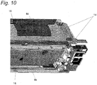
- Fig. 10 is a perspective view of the base 8b and the cover 8d installed.
- the cover 8d is mounted to the base 8b so as to be rotatable about a plurality of connections 14 to open upward. That is, the electrical unit 8 is provided with the plurality of connections 14 on an upper side thereof.
- the cover 8d has a protrusion 15 formed therewith or otherwise rigidly secured thereto, and the base 8b has a catch 16 similarly formed therewith or otherwise rigidly secured thereto. Engagement of the protrusion 15 of the cover 8d with the catch 16 of the base 8b prevents rotation of the cover 8d to thereby hold the cover 8d in a closed position.
- cover 8d and the base 8d may be so designed that the former has a catch and the latter has a protrusion
- the construction as described in this embodiment allows easy removal of the protrusion 15 from the catch 16 and subsequent rotation of the cover 8d toward an open direction by merely applying a force to the cover 8d in the open direction, thus enhancing the workability.
- the cover 8d can be opened by rotating the cover 8d upward about the plurality of connections 14, the interior of the electrical unit 8 accommodated in the indoor unit 1, which is normally installed high in a room, can be confirmed from below during maintenance, thus making it possible to enhance the workability during maintenance.
- Fig. 11A is an exploded perspective view of one of the plurality of connections 14, and Fig. 11B is a perspective view of the connection of Fig. 11A after assemblage.
- Maintenance work for the electrical unit 8 includes replacement of the substrate 8c and, hence, a construction of the electrical unit 8 that allows easy replacement of the substrate 8c can enhance the working efficiency.
- each connection 14 is configured to allow rotation of the cover 8d.
- each connection 14 includes a shaft hole 17 formed in the base 8b and a rotary shaft 18 mounted to the cover 8d.
- the rotary shaft 18 is provided with a stopper 19 to avoid removal of the rotary shaft 18 from the shaft hole 17.
- the rotary shaft 18 has a groove (not shown) defined therein, in which the stopper 19 is received.
- the stopper 19 is generally formed into a C and accordingly has an opening for insertion of the rotary shaft 18, thus resulting in easy attachment of the stopper 19 to the rotary shaft 18.
- Fig. 12A is a front view of the stopper 19, and as shown therein, the stopper 19 has two recesses defined therein at an inner periphery thereof. That is, the stopper 19 has two narrowed portions 20 each having a width L (distance between an inner peripheral edge and an outer peripheral edge) shorter than that of other portions.
- Fig. 12A depicts the stopper 19 having the two narrowed portions 20, but the present invention is not limited thereto.
- the stopper 19 may have only one narrowed portion 20 as shown in Fig. 12B or three or more narrowed portions.
- all the rotary shafts 18 are inserted into respective shaft holes 17 from the same direction to thereby enhance the workability during maintenance.
- the arrangement of the electrical unit 8 on a front side of the indoor unit 1 can increase the width (longitudinal length) of the indoor heat exchanger 5 to enhance the heat exchanging performance. Also, because the electrical unit 8 is positioned on a wind way or air-conveying path, the cooling effect on the electrical unit 8 can be enhanced. Further, because the flame-retardant member 12 acts to prevent foreign substances such as dust or dirt from entering the electrical unit 8, the air conditioner is highly reliable.
- the present invention is applicable not only to an air conditioner in which an indoor unit is connected to an outdoor unit, but also to a multi-air conditioner in which a plurality of indoor units are connected to an outdoor unit.
Landscapes
- Engineering & Computer Science (AREA)
- Chemical & Material Sciences (AREA)
- Combustion & Propulsion (AREA)
- Mechanical Engineering (AREA)
- General Engineering & Computer Science (AREA)
- Air Filters, Heat-Exchange Apparatuses, And Housings Of Air-Conditioning Units (AREA)
- Casings For Electric Apparatus (AREA)
Description
- The present invention relates to an arrangement of an electrical unit mounted in an indoor unit of an air conditioner.
- A conventional air conditioner includes an electrical unit accommodating electrical components therein and disposed on a front side of an indoor unit to increase the width of an indoor heat exchanger to thereby increase the amount of heat exchange (see, for example, Patent Document 1).
- Patent Document 1: Japanese Laid-Open Patent Publication No.
8-110085 EP2325572 discloses a n air conditioner upon which the preamble of appendingclaim 1 is based. - In the above-described conventional construction, however, because the electrical unit is positioned on a wind way, it is likely that dust, impure substances, or the like would be conveyed toward the electrical unit by a wind. Accordingly, it is necessary to prevent such impurities from entering the interior of the electrical unit.
- The present invention has been developed to overcome the above-described disadvantage.
- It is accordingly an objective of the present invention to provide an air conditioner capable of restraining impurities from entering the interior of the electrical unit.
- In accomplishing the above and other objectives, the air conditioner according to the present invention includes an indoor unit, an indoor heat exchanger placed in the indoor unit and an electrical unit, wherein the electrical unit includes a base, a substrate mounted on the base and having electrical components placed thereon, and a cover for covering the base. The base has a groove portion defined therein so as to extend along an outer periphery thereof, the cover has a protrusion formed therewith so as to be fitted into the groove portion, and the electrical unit is placed in the indoor unit at a location delimited by a front face of the indoor heat exchanger, an upper suction opening, and a front suction opening.
- The air conditioner according to the present invention is effective in restraining impurities from entering the electrical unit.
- The above and other objectives and features of the present invention will become more apparent from the following description of a preferred embodiment thereof with reference to the accompanying drawings, throughout which like parts are designated by like reference numerals, and wherein:
-
Fig. 1 is a perspective view of an indoor unit of an air conditioner embodying the present invention; -
Fig. 2A is a front view of the indoor unit ofFig. 1 ; -
Fig. 2B is a front view of the indoor unit ofFig. 1 with a front panel removed; -
Fig. 3A is a cross-sectional view taken along line A-A inFig. 2A when the indoor unit is not in operation; -
Fig. 3B is a cross-sectional view taken along line A-A inFig. 2A when the indoor unit is in operation; -
Fig. 4 is a perspective view of an electrical unit mounted in the indoor unit ofFig. 1 ; -
Fig. 5 is an exploded perspective view of the electrical unit ofFig. 4 ; -
Fig. 6 is an exploded perspective view of the indoor unit ofFig. 1 , particularly depicting a positional relationship between the electrical unit and a filter frame; -
Fig. 7 is a cross-sectional view taken along line B-B inFig. 4 ; -
Fig. 8 is an enlarged cross-sectional view of a mating portion between a base and a cover of the electrical unit ofFig. 4 ; -
Fig. 9A is an enlarged perspective view of a portion C encircled by a dotted line inFig. 4 ; -
Fig. 9B is a front view of the portion C as viewed from a direction indicated by D; -
Fig. 10 is a perspective view of the base and the cover installed; -
Fig. 11A is an exploded perspective view of one of a plurality of connections between the base and the cover; -
Fig. 11B is a perspective view of the connection ofFig. 11A after assemblage; -
Fig. 12A is a front view of a stopper mounted to the connection ofFig. 11A ; and -
Fig. 12B is a view similar toFig. 12A , but depicting a modification thereof. - An air conditioner according to the present invention includes an indoor unit and an electrical unit accommodated in the indoor unit on a front side thereof, wherein the electrical unit includes a base, a substrate mounted on the base and having electrical components placed thereon, and a cover for covering the base. The base has a groove portion defined therein so as to extend along an outer periphery thereof, and the cover has a protrusion formed therewith so as to be fitted into the groove portion. This configuration complicates a pathway of entry of impurities into the interior of the electrical unit, thus restraining the impurities from entering the electrical unit.
- Advantageously, a flame-retardant member is interposed between the base and the cover to enhance safety.
- It is preferred that the flame-retardant member be flexible to enhance the sealing performance between the base and the cover.
- Again advantageously, the base includes an inner side wall and an outer side wall confronting each other, and the groove portion is formed therebetween, the inner side wall being higher than the outer side wall. This configuration further prevents impurities from entering the electrical unit.
- It is also preferred that a sheet-metal cover for covering the cover be provided to prevent fire from spreading outside, thereby enhancing safety.
- An outer surface of the sheet-metal cover is preferably coated or painted to restrain a user from being injured by edges or burrs of the sheet-metal during maintenance, thus further enhancing safety.
- The cover preferably has a groove portion defined therein, in which an end portion of the sheet-metal cover is inserted. The groove portion acts to cover or conceal the edges of the sheet-metal cover, thereby further enhancing safety.
- A preferred embodiment of the present invention is explained hereinafter with reference to the drawings, but the present invention is not limited thereto.
-
Fig. 1 is a perspective view of an indoor unit of an air conditioner embodying the present invention.Fig. 2A is a front view of the indoor unit with a front panel installed, whileFig. 2B is a front view of the indoor unit with the front panel removed.Fig. 3A is a cross-sectional view taken along line A-A inFig. 2A when the indoor unit is not in operation, whileFig. 3B is a cross-sectional view taken along line A-A inFig. 2A when the indoor unit is in operation. - The air conditioner in this embodiment includes an
indoor unit 1 to be installed in a room and an outdoor unit (not shown) to be installed outside the room, both connected to each other via refrigerant piping and electric wires. - A construction of the
indoor unit 1 is explained hereinafter with reference toFig. 1, Figs. 2A and 2B , andFigs. 3A and 3B . - The
indoor unit 1 in this embodiment has anupper suction opening 2a defined in an upper wall thereof, through which indoor air is sucked from above, and afront suction opening 2b defined in a front wall thereof through which indoor air is sucked from front. Theindoor unit 1 includes afront panel 2 for covering thefront suction opening 2b from front. When theindoor unit 1 is brought into operation, thefront panel 2 moves forward to open thefront suction opening 2b, thereby increasing the amount of air sucked through thefront suction opening 2b. - Also, the
indoor unit 1 has a discharge opening 3 defined therein to blow out into a room air that has been sucked into theindoor unit 1. Theindoor unit 1 also includes a plurality of vertical winddirection changing blades 3a and a plurality of horizontal wind direction changing blades 3 disposed in proximity to the discharge opening 3 to vertically and horizontally change the direction of air blown out through the discharge opening 3, respectively. Theindoor unit 1 accommodates therein anindoor heat exchanger 5 generally in the form of an inverted V, an indoor fan 6 for conveying air sucked into theindoor unit 1 toward a room through the discharge opening 3, and anair filter 7 for collecting dust. Theair filter 7 is held by afilter frame 7a, on which an automatic cleaning device for automatically cleaning theair filter 7 is mounted. Detailed explanation of the automatic cleaning device is omitted. - Operation of the indoor fan 6 generates an air current, which in turn causes indoor air to be sucked into the
indoor unit 1 through theupper suction opening 2a and thefront suction opening 2b. The air sucked into theindoor unit 1 is heat exchanged with a refrigerant in theindoor heat exchanger 5 so that cold or warm air may be introduced into a room during cooling or heating. - In the
indoor unit 1 of the above-described construction, anelectrical unit 8 is disposed at a location delimited by theupper suction opening 2a, thefront suction opening 2b, and a front face of theindoor heat exchanger 5. This arrangement of theelectrical unit 8 can make effective use of a dead space delimited by theupper suction opening 2a, thefront suction opening 2b, and the front face of theindoor heat exchanger 5. Accordingly, it is not necessary to arrange theelectrical unit 8 lateral to theindoor heat exchanger 5 and, hence, the width of theindoor heat exchanger 5 can be increased, thus making it possible to enhance the heat exchanging performance of theindoor heat exchanger 5. - Also, the
electrical unit 8 includes a substrate, on which electrical components are placed, and accordingly generates heat, but theelectrical unit 8 is cooled by a wind (indoor air) sucked through theupper suction opening 2a andfront suction opening 2b. Further, because theelectrical unit 8 is disposed above theindoor heat exchanger 5, drainage water generated in theindoor heat exchanger 5 is prevented from dripping on theelectrical unit 8, thus making it possible to enhance the reliability. - A construction of the
electrical unit 8 is explained hereinafter.Fig. 4 is a perspective view of theelectrical unit 8, andFig. 5 is an exploded perspective view of theelectrical unit 8.Fig. 6 is an exploded perspective view depicting a positional relationship between theelectrical unit 8 and thefilter frame 7a. - As shown in
Figs. 4 to 6 , theelectrical unit 8 includes asupport plate 8a made by sheet-metal processing, abase 8b made of a flame-retardant resin, asubstrate 8c on which electrical components are placed, acover 8d made of a flame-retardant resin, and ametal cover 8e made by sheet-metal processing. An ABS resin and the like can be used for the flame-retardant resin to form thebase 8b and thecover 8d. - A
terminal block 8f is separately disposed lateral to theelectrical unit 8 and connected to electric wires that connect the electrical components on thesubstrate 8c and those accommodated in an outdoor unit (not shown). A connecting portion to which the electric wires are connected is positioned at the front to allow wiring or other work from a front side. - The
support plate 8a is disposed to support respective ends of thefilter frame 7a. Because thesupport plate 8a is made by sheet-metal processing, it can prevent deformation of theelectrical unit 8 that may be caused by an external force, for example, during transportation. Also, even if a worker applies an external force to theelectrical unit 8 during maintenance, the shape of thesupport plate 8a acts to restrain a reduction in the distance between theelectrical unit 8 and thefilter frame 7a, thereby ensuring a predetermined amount of air to be sucked into theindoor unit 1. It is to be noted that thefilter frame 7a and thesupport plate 8a may be connected to each other by screws or engaged with each other. - The
support plate 8a extends over an entire width (longitudinal direction) of thefilter frame 7a. Thesubstrate 8c is placed on a right side of thesupport plate 8a, and an opening orwind way 8g is formed on a left side of thesupport plate 8a so as not to impede an air current. Theopening 8g acts to reduce a resistance to draft. The arrangement (positional relationship) of thesubstrate 8c and theopening 8g is not particularly limited, and it may be reversed horizontally or vertically. -
Fig. 7 is a cross-sectional view taken along line B-B inFig. 4 depicting theelectrical unit 8, andFig. 8 is an enlarged cross-sectional view of a mating portion between thebase 8b and thecover 8d. As shown inFigs. 7 and8 , thebase 8b has a groove portion (groove configuration) 9 defined therein so as to extend along an outer periphery (circumference) thereof. That is, thebase 8b has aninner side wall 9a and anouter side wall 9b along the outer periphery thereof so as to confront each other, and thegroove portion 9 is formed between theinner side wall 9a and theouter side wall 9b. - On the other hand, the
cover 8d has aprotrusion 10 formed therewith at a location confronting thegroove portion 9. Thecover 8d is mounted to thebase 8b by fitting the protrusion (protruding portion) 10 into thegroove portion 9. A flame-retardant member 12 is interposed between theinner side wall 9a of thebase 8b and a portion of thecover 8d confronting theinner side wall 9a to enhance safety. - It is preferred that the
groove portion 9 and theprotrusion 10 be engaged with each other without any gap therebetween. It is, however, difficult to eliminate agap 11 due to, for example, manufacturing errors. - For this reason, it is preferred that the flame-
retardant member 12 be a flexible or elastic member such as, for example, an EPT sealing material. When thecover 8d is fitted to thebase 8b, the use of such a member allows deformation of the flame-retardant member 12, thereby filling thegap 11. - By doing so, it becomes possible to restrain foreign substances (impurities) from entering the
electrical unit 8 and also restrain fire, which may occur inside theelectrical unit 8, from spreading outside. - In this embodiment, the
groove portion 9 is formed between theinner side wall 9a and theouter side wall 9b, and a height H1 of theinner side wall 9a is higher than a height H2 of theouter side wall 9b. As a result, even if foreign substances enter thegroove portion 9 over theouter side wall 9b for some reason, they are restrained from penetrating inside of theelectrical unit 8 because of the presence of the higherinner side wall 9a. - Also, in this embodiment, the sheet-
metal cover 8e is mounted on thecover 8d to further restrain fire, which may occur inside theelectrical unit 8, from spreading outside. - Further, in this embodiment, an outer surface of the sheet-
metal cover 8e is coated or painted to thereby restrain a user from being injured by edges or burrs of the sheet-metal during maintenance. - In this embodiment, both the
cover 8d and the sheet-metal cover 8e are formed along theupper suction opening 2a and thefront suction opening 2b and, in particular, both thecover 8d and the sheet-metal cover 8e are generally formed into a trapezoidal shape. This shape allows theelectrical unit 8 to be accommodated in a generally triangular dead space that is formed by theupper suction opening 2a, thefront suction opening 2b, and the front face of theindoor heat exchanger 5. -
Fig. 9A is an enlarged perspective view of a portion C encircled by a dotted line inFig. 4 , andFig. 9B is a front view of the portion C as viewed from a direction of D inFig. 9A . - As shown in
Figs. 9A and 9B , thecover 8d has agroove portion 13 defined therein, in which an end portion of the sheet-metal cover 8e is inserted for fixation of the sheet-metal cover 8e on thecover 8d. - The
groove portion 13 accommodates or covers edges of the sheet-metal cover 8e, thus enhancing safety during maintenance. - How to mount the
cover 8d to thebase 8b is explained hereinafter.Fig. 10 is a perspective view of thebase 8b and thecover 8d installed. - As shown in
Fig. 10 , thecover 8d is mounted to thebase 8b so as to be rotatable about a plurality ofconnections 14 to open upward. That is, theelectrical unit 8 is provided with the plurality ofconnections 14 on an upper side thereof. - The
cover 8d has aprotrusion 15 formed therewith or otherwise rigidly secured thereto, and thebase 8b has acatch 16 similarly formed therewith or otherwise rigidly secured thereto. Engagement of theprotrusion 15 of thecover 8d with thecatch 16 of thebase 8b prevents rotation of thecover 8d to thereby hold thecover 8d in a closed position. - Although the
cover 8d and thebase 8d may be so designed that the former has a catch and the latter has a protrusion, the construction as described in this embodiment allows easy removal of theprotrusion 15 from thecatch 16 and subsequent rotation of thecover 8d toward an open direction by merely applying a force to thecover 8d in the open direction, thus enhancing the workability. - Because the
cover 8d can be opened by rotating thecover 8d upward about the plurality ofconnections 14, the interior of theelectrical unit 8 accommodated in theindoor unit 1, which is normally installed high in a room, can be confirmed from below during maintenance, thus making it possible to enhance the workability during maintenance. - A configuration of the
connections 14 is explained hereinafter.Fig. 11A is an exploded perspective view of one of the plurality ofconnections 14, andFig. 11B is a perspective view of the connection ofFig. 11A after assemblage. - Maintenance work for the
electrical unit 8 includes replacement of thesubstrate 8c and, hence, a construction of theelectrical unit 8 that allows easy replacement of thesubstrate 8c can enhance the working efficiency. - In view of this, in this embodiment, the
connections 14 are configured to allow rotation of thecover 8d. Specifically, eachconnection 14 includes ashaft hole 17 formed in thebase 8b and arotary shaft 18 mounted to thecover 8d. - In this embodiment, the
rotary shaft 18 is provided with astopper 19 to avoid removal of therotary shaft 18 from theshaft hole 17. Therotary shaft 18 has a groove (not shown) defined therein, in which thestopper 19 is received. Thestopper 19 is generally formed into a C and accordingly has an opening for insertion of therotary shaft 18, thus resulting in easy attachment of thestopper 19 to therotary shaft 18. -
Fig. 12A is a front view of thestopper 19, and as shown therein, thestopper 19 has two recesses defined therein at an inner periphery thereof. That is, thestopper 19 has two narrowedportions 20 each having a width L (distance between an inner peripheral edge and an outer peripheral edge) shorter than that of other portions. - The narrowed
portions 20 allow thestopper 19 to elastically deform outward when thestopper 19 is attached to therotary shaft 18.Fig. 12A depicts thestopper 19 having the two narrowedportions 20, but the present invention is not limited thereto. By way of example, thestopper 19 may have only one narrowedportion 20 as shown inFig. 12B or three or more narrowed portions. - Also, in the plurality of
connections 14 in this embodiment, all therotary shafts 18 are inserted into respective shaft holes 17 from the same direction to thereby enhance the workability during maintenance. - As described above, according to the air conditioner in this embodiment, the arrangement of the
electrical unit 8 on a front side of theindoor unit 1 can increase the width (longitudinal length) of theindoor heat exchanger 5 to enhance the heat exchanging performance. Also, because theelectrical unit 8 is positioned on a wind way or air-conveying path, the cooling effect on theelectrical unit 8 can be enhanced. Further, because the flame-retardant member 12 acts to prevent foreign substances such as dust or dirt from entering theelectrical unit 8, the air conditioner is highly reliable. - Although the present invention has been fully described by way of a preferred embodiment with reference to the accompanying drawings, it is to be noted here that various changes and modifications will be apparent to those skilled in the art. Therefore, unless such changes and modifications otherwise depart from the scope of the appended claims, they should be construed as being included therein.
- The present invention is applicable not only to an air conditioner in which an indoor unit is connected to an outdoor unit, but also to a multi-air conditioner in which a plurality of indoor units are connected to an outdoor unit.
-
- 1
- indoor unit
- 2
- front panel
- 8
- electrical unit
- 8a
- support plate
- 8b
- base
- 8c
- substrate
- 8d
- cover
- 8e
- sheet-metal cover
- 8f
- terminal block
- 9
- groove portion
- 10
- protrusion
Claims (7)
- An air conditioner comprising an indoor unit (1), an indoor heat exchanger (5) placed in the indoor unit (1), and an electrical unit (8), wherein the electrical unit (8) comprises a base (8b), a substrate (8c) mounted on the base (8b) and having electrical components placed thereon, and a cover (8d) for covering the base (8b), wherein the base (8b) has a groove portion (9) defined therein so as to extend along an outer periphery thereof,
the cover (8d) has a protrusion (10) formed therewith so as to be fitted into the groove portion (9), and characterized in that the electrical unit (8) is placed in the indoor unit (1) at a location delimited by a front face of the indoor heat exchanger (5), an upper suction opening (2a), and a front suction opening (2b). - The air conditioner according to claim 1, further comprising a flame-retardant member (12) interposed between the base (8b) and the cover (8d).
- The air conditioner according to claim 2, wherein the flame-retardant member (12) is flexible.
- The air conditioner according to any one of claims 1 to 3, wherein the base (8b) comprises an inner side wall (9a) and an outer side wall (9b) confronting each other, and the groove portion (9) is formed therebetween, the inner side wall (9a) being higher than the outer side wall (9b).
- The air conditioner according to any one of claims 1 to 4, further comprising a sheet-metal cover (8e) for covering the cover (8d).
- The air conditioner according to claim 5, wherein an outer surface of the sheet-metal cover (8e) is coated or painted.
- The air conditioner according to claim 5 or 6, wherein the cover (8d) has a groove portion (9) defined therein, in which an end portion of the sheet-metal cover (8e) is inserted.
Applications Claiming Priority (1)
| Application Number | Priority Date | Filing Date | Title |
|---|---|---|---|
| JP2011192676A JP2013053820A (en) | 2011-09-05 | 2011-09-05 | Air conditioner |
Publications (3)
| Publication Number | Publication Date |
|---|---|
| EP2565544A2 EP2565544A2 (en) | 2013-03-06 |
| EP2565544A3 EP2565544A3 (en) | 2015-01-07 |
| EP2565544B1 true EP2565544B1 (en) | 2018-11-14 |
Family
ID=45808233
Family Applications (1)
| Application Number | Title | Priority Date | Filing Date |
|---|---|---|---|
| EP12157833.0A Active EP2565544B1 (en) | 2011-09-05 | 2012-03-02 | Air conditioner |
Country Status (3)
| Country | Link |
|---|---|
| EP (1) | EP2565544B1 (en) |
| JP (1) | JP2013053820A (en) |
| CN (1) | CN102980246A (en) |
Family Cites Families (13)
| Publication number | Priority date | Publication date | Assignee | Title |
|---|---|---|---|---|
| JPH0440111Y2 (en) * | 1986-07-17 | 1992-09-21 | ||
| JPH08110085A (en) | 1994-10-14 | 1996-04-30 | Hitachi Ltd | Indoor unit |
| JPH0964562A (en) * | 1995-08-30 | 1997-03-07 | Yamatake Honeywell Co Ltd | Bracket for fixing electric apparatus |
| JPH10132326A (en) * | 1996-10-25 | 1998-05-22 | Sanyo Electric Co Ltd | Air conditioner |
| JP3423190B2 (en) * | 1997-06-05 | 2003-07-07 | 三洋電機株式会社 | Air conditioner |
| JPH11159800A (en) * | 1997-11-28 | 1999-06-15 | Matsushita Electric Ind Co Ltd | Electric parts containing box for air conditioner |
| JP3259719B2 (en) * | 1999-08-31 | 2002-02-25 | ダイキン工業株式会社 | Air conditioner |
| JP2002206770A (en) * | 2002-01-15 | 2002-07-26 | Daikin Ind Ltd | Air conditioner |
| JP3730604B2 (en) * | 2002-08-01 | 2006-01-05 | 三菱電機株式会社 | Indoor unit of air conditioner |
| CN1755213A (en) * | 2004-09-30 | 2006-04-05 | 乐金电子(天津)电器有限公司 | Indoor unit of air conditioner |
| CN1987237A (en) * | 2005-12-22 | 2007-06-27 | 乐金电子(天津)电器有限公司 | Control box of air conditioner indoor machine |
| JP5084813B2 (en) * | 2009-11-18 | 2012-11-28 | 三菱電機株式会社 | Air conditioner |
| JP2013124804A (en) * | 2011-12-14 | 2013-06-24 | Panasonic Corp | Air conditioner |
-
2011
- 2011-09-05 JP JP2011192676A patent/JP2013053820A/en active Pending
-
2012
- 2012-02-28 CN CN2012100483883A patent/CN102980246A/en active Pending
- 2012-03-02 EP EP12157833.0A patent/EP2565544B1/en active Active
Non-Patent Citations (1)
| Title |
|---|
| None * |
Also Published As
| Publication number | Publication date |
|---|---|
| CN102980246A (en) | 2013-03-20 |
| EP2565544A3 (en) | 2015-01-07 |
| EP2565544A2 (en) | 2013-03-06 |
| JP2013053820A (en) | 2013-03-21 |
Similar Documents
| Publication | Publication Date | Title |
|---|---|---|
| KR102168584B1 (en) | Indoor unit of ceiling type air-conditioner | |
| EP3128243B1 (en) | Air conditioner outdoor unit | |
| US20170336092A1 (en) | Air conditioner | |
| JP6289663B2 (en) | Air conditioner indoor unit | |
| JP5370191B2 (en) | Air conditioner indoor unit | |
| JP5471309B2 (en) | Duct type air conditioner | |
| WO2016136351A1 (en) | Air-conditioner outdoor unit | |
| WO2014091800A1 (en) | Outdoor machine for air-conditioner | |
| JP4888435B2 (en) | Air conditioner | |
| CN106716022B (en) | The outdoor unit of refrigerating circulatory device | |
| JP2011158108A (en) | Outdoor unit for air conditioner | |
| US20200386439A1 (en) | Heat source unit for refrigeration device | |
| EP2568225B1 (en) | Air Conditioner | |
| EP2551607B1 (en) | Ventilation apparatus | |
| EP2565544B1 (en) | Air conditioner | |
| WO2013088658A1 (en) | Air conditioner | |
| JP5071573B2 (en) | Air conditioner | |
| JP6180262B2 (en) | Air conditioner indoor unit | |
| JP5492626B2 (en) | Air conditioner indoor unit | |
| CN211739320U (en) | Outdoor machine of air conditioner | |
| JP4739893B2 (en) | Air conditioner | |
| JP6160156B2 (en) | Air conditioning indoor unit | |
| EP3006856A2 (en) | Indoor unit and air conditioner | |
| JP5071600B2 (en) | Air conditioner | |
| KR20150120218A (en) | Indoor unit for air conditioner |
Legal Events
| Date | Code | Title | Description |
|---|---|---|---|
| PUAI | Public reference made under article 153(3) epc to a published international application that has entered the european phase |
Free format text: ORIGINAL CODE: 0009012 |
|
| AK | Designated contracting states |
Kind code of ref document: A2 Designated state(s): AL AT BE BG CH CY CZ DE DK EE ES FI FR GB GR HR HU IE IS IT LI LT LU LV MC MK MT NL NO PL PT RO RS SE SI SK SM TR |
|
| AX | Request for extension of the european patent |
Extension state: BA ME |
|
| PUAL | Search report despatched |
Free format text: ORIGINAL CODE: 0009013 |
|
| AK | Designated contracting states |
Kind code of ref document: A3 Designated state(s): AL AT BE BG CH CY CZ DE DK EE ES FI FR GB GR HR HU IE IS IT LI LT LU LV MC MK MT NL NO PL PT RO RS SE SI SK SM TR |
|
| AX | Request for extension of the european patent |
Extension state: BA ME |
|
| RIC1 | Information provided on ipc code assigned before grant |
Ipc: F24F 13/20 20060101ALI20141128BHEP Ipc: F24F 1/00 20110101AFI20141128BHEP |
|
| 17P | Request for examination filed |
Effective date: 20150707 |
|
| RBV | Designated contracting states (corrected) |
Designated state(s): AL AT BE BG CH CY CZ DE DK EE ES FI FR GB GR HR HU IE IS IT LI LT LU LV MC MK MT NL NO PL PT RO RS SE SI SK SM TR |
|
| STAA | Information on the status of an ep patent application or granted ep patent |
Free format text: STATUS: EXAMINATION IS IN PROGRESS |
|
| 17Q | First examination report despatched |
Effective date: 20170515 |
|
| GRAP | Despatch of communication of intention to grant a patent |
Free format text: ORIGINAL CODE: EPIDOSNIGR1 |
|
| STAA | Information on the status of an ep patent application or granted ep patent |
Free format text: STATUS: GRANT OF PATENT IS INTENDED |
|
| INTG | Intention to grant announced |
Effective date: 20180530 |
|
| GRAS | Grant fee paid |
Free format text: ORIGINAL CODE: EPIDOSNIGR3 |
|
| GRAA | (expected) grant |
Free format text: ORIGINAL CODE: 0009210 |
|
| STAA | Information on the status of an ep patent application or granted ep patent |
Free format text: STATUS: THE PATENT HAS BEEN GRANTED |
|
| AK | Designated contracting states |
Kind code of ref document: B1 Designated state(s): AL AT BE BG CH CY CZ DE DK EE ES FI FR GB GR HR HU IE IS IT LI LT LU LV MC MK MT NL NO PL PT RO RS SE SI SK SM TR |
|
| REG | Reference to a national code |
Ref country code: CH Ref legal event code: EP Ref country code: AT Ref legal event code: REF Ref document number: 1065283 Country of ref document: AT Kind code of ref document: T Effective date: 20181115 |
|
| REG | Reference to a national code |
Ref country code: DE Ref legal event code: R096 Ref document number: 602012053383 Country of ref document: DE |
|
| REG | Reference to a national code |
Ref country code: IE Ref legal event code: FG4D |
|
| REG | Reference to a national code |
Ref country code: NL Ref legal event code: MP Effective date: 20181114 |
|
| REG | Reference to a national code |
Ref country code: LT Ref legal event code: MG4D |
|
| REG | Reference to a national code |
Ref country code: AT Ref legal event code: MK05 Ref document number: 1065283 Country of ref document: AT Kind code of ref document: T Effective date: 20181114 |
|
| PG25 | Lapsed in a contracting state [announced via postgrant information from national office to epo] |
Ref country code: IS Free format text: LAPSE BECAUSE OF FAILURE TO SUBMIT A TRANSLATION OF THE DESCRIPTION OR TO PAY THE FEE WITHIN THE PRESCRIBED TIME-LIMIT Effective date: 20190314 Ref country code: FI Free format text: LAPSE BECAUSE OF FAILURE TO SUBMIT A TRANSLATION OF THE DESCRIPTION OR TO PAY THE FEE WITHIN THE PRESCRIBED TIME-LIMIT Effective date: 20181114 Ref country code: AT Free format text: LAPSE BECAUSE OF FAILURE TO SUBMIT A TRANSLATION OF THE DESCRIPTION OR TO PAY THE FEE WITHIN THE PRESCRIBED TIME-LIMIT Effective date: 20181114 Ref country code: LV Free format text: LAPSE BECAUSE OF FAILURE TO SUBMIT A TRANSLATION OF THE DESCRIPTION OR TO PAY THE FEE WITHIN THE PRESCRIBED TIME-LIMIT Effective date: 20181114 Ref country code: NO Free format text: LAPSE BECAUSE OF FAILURE TO SUBMIT A TRANSLATION OF THE DESCRIPTION OR TO PAY THE FEE WITHIN THE PRESCRIBED TIME-LIMIT Effective date: 20190214 Ref country code: LT Free format text: LAPSE BECAUSE OF FAILURE TO SUBMIT A TRANSLATION OF THE DESCRIPTION OR TO PAY THE FEE WITHIN THE PRESCRIBED TIME-LIMIT Effective date: 20181114 Ref country code: ES Free format text: LAPSE BECAUSE OF FAILURE TO SUBMIT A TRANSLATION OF THE DESCRIPTION OR TO PAY THE FEE WITHIN THE PRESCRIBED TIME-LIMIT Effective date: 20181114 Ref country code: BG Free format text: LAPSE BECAUSE OF FAILURE TO SUBMIT A TRANSLATION OF THE DESCRIPTION OR TO PAY THE FEE WITHIN THE PRESCRIBED TIME-LIMIT Effective date: 20190214 Ref country code: HR Free format text: LAPSE BECAUSE OF FAILURE TO SUBMIT A TRANSLATION OF THE DESCRIPTION OR TO PAY THE FEE WITHIN THE PRESCRIBED TIME-LIMIT Effective date: 20181114 |
|
| PG25 | Lapsed in a contracting state [announced via postgrant information from national office to epo] |
Ref country code: AL Free format text: LAPSE BECAUSE OF FAILURE TO SUBMIT A TRANSLATION OF THE DESCRIPTION OR TO PAY THE FEE WITHIN THE PRESCRIBED TIME-LIMIT Effective date: 20181114 Ref country code: PT Free format text: LAPSE BECAUSE OF FAILURE TO SUBMIT A TRANSLATION OF THE DESCRIPTION OR TO PAY THE FEE WITHIN THE PRESCRIBED TIME-LIMIT Effective date: 20190314 Ref country code: SE Free format text: LAPSE BECAUSE OF FAILURE TO SUBMIT A TRANSLATION OF THE DESCRIPTION OR TO PAY THE FEE WITHIN THE PRESCRIBED TIME-LIMIT Effective date: 20181114 Ref country code: NL Free format text: LAPSE BECAUSE OF FAILURE TO SUBMIT A TRANSLATION OF THE DESCRIPTION OR TO PAY THE FEE WITHIN THE PRESCRIBED TIME-LIMIT Effective date: 20181114 Ref country code: RS Free format text: LAPSE BECAUSE OF FAILURE TO SUBMIT A TRANSLATION OF THE DESCRIPTION OR TO PAY THE FEE WITHIN THE PRESCRIBED TIME-LIMIT Effective date: 20181114 Ref country code: GR Free format text: LAPSE BECAUSE OF FAILURE TO SUBMIT A TRANSLATION OF THE DESCRIPTION OR TO PAY THE FEE WITHIN THE PRESCRIBED TIME-LIMIT Effective date: 20190215 |
|
| PG25 | Lapsed in a contracting state [announced via postgrant information from national office to epo] |
Ref country code: CZ Free format text: LAPSE BECAUSE OF FAILURE TO SUBMIT A TRANSLATION OF THE DESCRIPTION OR TO PAY THE FEE WITHIN THE PRESCRIBED TIME-LIMIT Effective date: 20181114 Ref country code: PL Free format text: LAPSE BECAUSE OF FAILURE TO SUBMIT A TRANSLATION OF THE DESCRIPTION OR TO PAY THE FEE WITHIN THE PRESCRIBED TIME-LIMIT Effective date: 20181114 Ref country code: DK Free format text: LAPSE BECAUSE OF FAILURE TO SUBMIT A TRANSLATION OF THE DESCRIPTION OR TO PAY THE FEE WITHIN THE PRESCRIBED TIME-LIMIT Effective date: 20181114 Ref country code: IT Free format text: LAPSE BECAUSE OF FAILURE TO SUBMIT A TRANSLATION OF THE DESCRIPTION OR TO PAY THE FEE WITHIN THE PRESCRIBED TIME-LIMIT Effective date: 20181114 |
|
| REG | Reference to a national code |
Ref country code: DE Ref legal event code: R097 Ref document number: 602012053383 Country of ref document: DE |
|
| PG25 | Lapsed in a contracting state [announced via postgrant information from national office to epo] |
Ref country code: EE Free format text: LAPSE BECAUSE OF FAILURE TO SUBMIT A TRANSLATION OF THE DESCRIPTION OR TO PAY THE FEE WITHIN THE PRESCRIBED TIME-LIMIT Effective date: 20181114 Ref country code: SM Free format text: LAPSE BECAUSE OF FAILURE TO SUBMIT A TRANSLATION OF THE DESCRIPTION OR TO PAY THE FEE WITHIN THE PRESCRIBED TIME-LIMIT Effective date: 20181114 Ref country code: RO Free format text: LAPSE BECAUSE OF FAILURE TO SUBMIT A TRANSLATION OF THE DESCRIPTION OR TO PAY THE FEE WITHIN THE PRESCRIBED TIME-LIMIT Effective date: 20181114 Ref country code: SK Free format text: LAPSE BECAUSE OF FAILURE TO SUBMIT A TRANSLATION OF THE DESCRIPTION OR TO PAY THE FEE WITHIN THE PRESCRIBED TIME-LIMIT Effective date: 20181114 |
|
| PLBE | No opposition filed within time limit |
Free format text: ORIGINAL CODE: 0009261 |
|
| STAA | Information on the status of an ep patent application or granted ep patent |
Free format text: STATUS: NO OPPOSITION FILED WITHIN TIME LIMIT |
|
| 26N | No opposition filed |
Effective date: 20190815 |
|
| PG25 | Lapsed in a contracting state [announced via postgrant information from national office to epo] |
Ref country code: MC Free format text: LAPSE BECAUSE OF FAILURE TO SUBMIT A TRANSLATION OF THE DESCRIPTION OR TO PAY THE FEE WITHIN THE PRESCRIBED TIME-LIMIT Effective date: 20181114 Ref country code: SI Free format text: LAPSE BECAUSE OF FAILURE TO SUBMIT A TRANSLATION OF THE DESCRIPTION OR TO PAY THE FEE WITHIN THE PRESCRIBED TIME-LIMIT Effective date: 20181114 |
|
| REG | Reference to a national code |
Ref country code: CH Ref legal event code: PL |
|
| GBPC | Gb: european patent ceased through non-payment of renewal fee |
Effective date: 20190302 |
|
| PG25 | Lapsed in a contracting state [announced via postgrant information from national office to epo] |
Ref country code: LU Free format text: LAPSE BECAUSE OF NON-PAYMENT OF DUE FEES Effective date: 20190302 |
|
| REG | Reference to a national code |
Ref country code: BE Ref legal event code: MM Effective date: 20190331 |
|
| PG25 | Lapsed in a contracting state [announced via postgrant information from national office to epo] |
Ref country code: GB Free format text: LAPSE BECAUSE OF NON-PAYMENT OF DUE FEES Effective date: 20190302 Ref country code: IE Free format text: LAPSE BECAUSE OF NON-PAYMENT OF DUE FEES Effective date: 20190302 Ref country code: LI Free format text: LAPSE BECAUSE OF NON-PAYMENT OF DUE FEES Effective date: 20190331 Ref country code: CH Free format text: LAPSE BECAUSE OF NON-PAYMENT OF DUE FEES Effective date: 20190331 |
|
| PG25 | Lapsed in a contracting state [announced via postgrant information from national office to epo] |
Ref country code: BE Free format text: LAPSE BECAUSE OF NON-PAYMENT OF DUE FEES Effective date: 20190331 Ref country code: FR Free format text: LAPSE BECAUSE OF NON-PAYMENT OF DUE FEES Effective date: 20190331 |
|
| PG25 | Lapsed in a contracting state [announced via postgrant information from national office to epo] |
Ref country code: TR Free format text: LAPSE BECAUSE OF FAILURE TO SUBMIT A TRANSLATION OF THE DESCRIPTION OR TO PAY THE FEE WITHIN THE PRESCRIBED TIME-LIMIT Effective date: 20181114 |
|
| PG25 | Lapsed in a contracting state [announced via postgrant information from national office to epo] |
Ref country code: MT Free format text: LAPSE BECAUSE OF NON-PAYMENT OF DUE FEES Effective date: 20190302 |
|
| PG25 | Lapsed in a contracting state [announced via postgrant information from national office to epo] |
Ref country code: CY Free format text: LAPSE BECAUSE OF FAILURE TO SUBMIT A TRANSLATION OF THE DESCRIPTION OR TO PAY THE FEE WITHIN THE PRESCRIBED TIME-LIMIT Effective date: 20181114 |
|
| PG25 | Lapsed in a contracting state [announced via postgrant information from national office to epo] |
Ref country code: HU Free format text: LAPSE BECAUSE OF FAILURE TO SUBMIT A TRANSLATION OF THE DESCRIPTION OR TO PAY THE FEE WITHIN THE PRESCRIBED TIME-LIMIT; INVALID AB INITIO Effective date: 20120302 |
|
| PG25 | Lapsed in a contracting state [announced via postgrant information from national office to epo] |
Ref country code: MK Free format text: LAPSE BECAUSE OF FAILURE TO SUBMIT A TRANSLATION OF THE DESCRIPTION OR TO PAY THE FEE WITHIN THE PRESCRIBED TIME-LIMIT Effective date: 20181114 |
|
| PGFP | Annual fee paid to national office [announced via postgrant information from national office to epo] |
Ref country code: DE Payment date: 20220609 Year of fee payment: 12 |