EP2325572A2 - Air conditioner - Google Patents
Air conditioner Download PDFInfo
- Publication number
- EP2325572A2 EP2325572A2 EP10008470A EP10008470A EP2325572A2 EP 2325572 A2 EP2325572 A2 EP 2325572A2 EP 10008470 A EP10008470 A EP 10008470A EP 10008470 A EP10008470 A EP 10008470A EP 2325572 A2 EP2325572 A2 EP 2325572A2
- Authority
- EP
- European Patent Office
- Prior art keywords
- case
- lid body
- cover
- container portion
- opening
- Prior art date
- Legal status (The legal status is an assumption and is not a legal conclusion. Google has not performed a legal analysis and makes no representation as to the accuracy of the status listed.)
- Granted
Links
- 210000000078 claw Anatomy 0.000 claims abstract description 50
- 239000002184 metal Substances 0.000 claims abstract description 24
- 239000011347 resin Substances 0.000 claims abstract description 18
- 229920005989 resin Polymers 0.000 claims abstract description 18
- 230000002401 inhibitory effect Effects 0.000 claims abstract description 9
- 230000002093 peripheral effect Effects 0.000 claims description 20
- 238000005452 bending Methods 0.000 description 2
- 238000004378 air conditioning Methods 0.000 description 1
- 230000007547 defect Effects 0.000 description 1
- 238000009434 installation Methods 0.000 description 1
- 238000000034 method Methods 0.000 description 1
- 239000000758 substrate Substances 0.000 description 1
Images


Classifications
-
- F—MECHANICAL ENGINEERING; LIGHTING; HEATING; WEAPONS; BLASTING
- F24—HEATING; RANGES; VENTILATING
- F24F—AIR-CONDITIONING; AIR-HUMIDIFICATION; VENTILATION; USE OF AIR CURRENTS FOR SCREENING
- F24F1/00—Room units for air-conditioning, e.g. separate or self-contained units or units receiving primary air from a central station
- F24F1/0007—Indoor units, e.g. fan coil units
- F24F1/0043—Indoor units, e.g. fan coil units characterised by mounting arrangements
- F24F1/0057—Indoor units, e.g. fan coil units characterised by mounting arrangements mounted in or on a wall
-
- F—MECHANICAL ENGINEERING; LIGHTING; HEATING; WEAPONS; BLASTING
- F24—HEATING; RANGES; VENTILATING
- F24F—AIR-CONDITIONING; AIR-HUMIDIFICATION; VENTILATION; USE OF AIR CURRENTS FOR SCREENING
- F24F13/00—Details common to, or for air-conditioning, air-humidification, ventilation or use of air currents for screening
- F24F13/20—Casings or covers
- F24F2013/207—Casings or covers with control knobs; Mounting controlling members or control units therein
Definitions
- the present invention relates to a wall-hung type air conditioner provided with a heat exchanger, a fan, and an electric equipment box inside a main body of an indoor unit.
- the electric equipment box in an indoor unit of a wall-hung type air conditioner provided with a heat exchanger, a fan, and an electric equipment box inside a main body of the indoor unit, the electric equipment box includes a portion in which a case made of sheet metal is fitted around a container portion made of resin containing an electric substrate, a lid body made of sheet metal covering the center part and an upper part of an opening in the container portion, and a cover made of resin covering a lower part of the opening of the container portion, and the lid body made of the sheet metal includes an engagement claw at an upper part thereof to be inserted into the case of the electric equipment box and the cover made of the resin includes an engagement claw for pressing the lower part of the lid body made of sheet metal (See patent documents No.1, for example).
- the container portion made of resin or the engagement claw of the cover made of resin might be burned by the flame and melted, and there is a risk that the flame might spread to the main body of the electric equipment box, a design panel and the like from a locking hole of the case made of sheet metal or the lid body made of sheet metal or a gap in an abutted-and-bent portion of the sheet metal.
- the present invention was made in order to solve the above problems and an object thereof is to obtain an air conditioner in which even if a flame is generated inside the electric equipment box, the flame does not spread to the outside thereof.
- An air conditioner includes, in a wall-hung type air conditioner provided with a heat exchanger, a fan, and an electric equipment box in a main body of an indoor unit, the electric equipment box includes a container portion made of resin containing a control board, a terminal block and the like and having an opening portion in which a locking claw is disposed on the outer peripheral face, a case made of sheet metal having an opening portion having a locking hole engaged with the locking claw of the container portion on the outer periphery, a cover made of resin having an opening portion having a locking claw on the outer peripheral face, and a lid body made of sheet metal having an opening portion having a locking hole engaged with the locking claw of the cover on the outer periphery, the locking claw of the container portion is engaged with the locking hole of the case so as to cover the outer peripheral face of the container portion by the case, the locking claw of the cover is engaged with the locking hole of the lid body so as to cover the outer peripheral face of the cover by the lid body, they are assembled so that a part of an opening
- the locking claw disposed on the outer peripheral face of the container portion made of resin in which the control board, the terminal block and the like are contained is engaged with the locking hole disposed in the outer periphery of the case made of sheet metal so as to cover the outer peripheral face of the container portion by the case
- the locking claw disposed on the outer peripheral face of the cover is engaged with the locking hole disposed in the outer periphery of the lid body so as to cover the outer peripheral face of the cover by the lid body
- the electric equipment box is formed by fixing the container portion and the case as well as the cover and the lid body by the fastening means
- the flame spread inhibiting path of a predetermined length is formed between the opening end of the lid body and the opening end of the case, in which the opening edge of the lid body and the opening edge of the case overlap.
- the flame in the electric equipment box can be reliably prevented from leaving the assembled portions between the container portion of the electric equipment box and the case and between the cover and the lid body, and spread of flame to the main body, the design panel and the like of the indoor unit can be prevented.
- Fig. 1 is an exploded perspective view illustrating an indoor unit of an air conditioner of Embodiment 1 of the present invention
- Fig. 2 is a longitudinal sectional view of the center in a main body of the indoor unit of the air conditioner
- Fig. 3 is a perspective view illustrating an electric equipment box of the indoor unit of the air conditioner
- Fig. 4 is an exploded perspective view illustrating the electric equipment box of the indoor unit of the air conditioner
- Fig. 5 is an exploded perspective view of a container portion and a case of the electric equipment box of the indoor unit of the air conditioner
- Fig. 6 is an exploded perspective view of a cover and a lid body of the electric equipment box of the indoor unit of the air conditioner
- Fig. 1 is an exploded perspective view illustrating an indoor unit of an air conditioner of Embodiment 1 of the present invention
- Fig. 2 is a longitudinal sectional view of the center in a main body of the indoor unit of the air conditioner
- Fig. 3 is a perspective view illustrating an electric equipment box
- the air conditioner of Embodiment 1 of the present invention is of a separate type and includes a wall-hung indoor unit and an outdoor unit (not shown) that performs air conditioning of indoor air, in which a main body 1 of the indoor unit has a design panel 2 which covers components inside on the front face side, an inlet 3 that sucks the indoor air disposed on a top face, and an outlet 4 that feeds heat-exchanged air into the room on a lower front face.
- a heat exchanger 5 that cools or over-heats the indoor air
- a fan 6 that blows the indoor air
- a fan casing 7 that forma an air path along which the air that has passed through the heat exchanger 5 is led to the outlet 4 of the design panel 2.
- an electric equipment box 8 that drives the fan 6 or the like is arranged on the right side of the air path of the fan casing 7 in the main body 1 of the indoor unit.
- the electric equipment box 8 includes a container portion 12 made of flame-resistant resin and having one face of the box thereof shape open so as to receive a control board 10, a terminal block 11 or the like, a case 13 made of sheet metal and covering the outer peripheral face other than an opening portion 24 of the container portion 12, a cover 14 made of flame-resistant resin, having one face of the box shape thereof open and covering the outer periphery other than the opening portion of the case 13, is slightly larger than the outer periphery and is removable by a screw or the like, a lid body 15 made of sheet metal and covering the outer peripheral faces other than the opening portion of the cover 14, a terminal block cover 16 made of flame-resistant resin and covering the terminal block 11, and a terminal block case 17 made of sheet metal and covering the terminal block cover 16.
- An internal/external connection line (not shown) is connected to the terminal block 11.
- Reference numeral 18 denotes a connection-line guiding member provided so as to be continuous with the container portion 12 and guiding the internal/external connection line to the terminal block 11.
- two locking claws 20 are disposed on the outer peripheral faces, other than the opening portion of the container portion 12 in the electric equipment box 8, while two locking holes 21 engaged with the locking claws 20 in the container portion 12 are disposed in the outer periphery other than the opening portion of the case 13 covering the container portion 12.
- two locking claws 22 are disposed on the outer peripheral faces, other than the opening portion of the cover 14, and two locking holes 23 engaged with the locking claws 22 of the cover 14 are disposed in the outer periphery, other than the opening portion of the lid body 15 covering the cover 14.
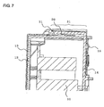
- a flame spread inhibiting path 31 of a predetermined length in which the opening edge of the lid body 15 and the portion of the opening edge of the case 13 overlap is formed between the opening end of the lid body 15 and the opening end on the locking hole 21 side of the case 13.
- the locking claws 20 disposed on the outer peripheral faces of the container portion 12 made of resin and containing the control board 10, the terminal block 11 and the like are engaged with the locking holes 21 disposed in the outer periphery of the case 13 made of sheet metal, and the outer peripheral face of the container portion 12 is covered by the case 13.
- the locking claws 22 disposed on the outer peripheral face of the cover 14 are engaged with the locking holes 23 disposed in the outer periphery of the lid body 15, and the outer peripheral face of the cover 14 is covered by the lid body 15.
- the components are assembled so that a part of the opening edge of the opening portion of the case 13 covering the container portion 12 is covered by the opening edge of the opening portion of the cover 14 covered by the lid body 15.
- the flame spread inhibiting path 31 of a predetermined length in which the opening edge of the lid body 15 and the opening edge of the case 13 overlap is formed between the opening end of the lid body 15 and the opening end on the locking hole 21 side of the case 13.
- the container portion 12 and the case 13 as well as the cover 14 and the lid body 15 are fixed by a screw, which is the fastening means, so as to form the electric equipment box 8.
- the indoor unit of the air conditioner of Embodiment 1 of the present invention when power is turned on, the fan 6 is driven by a control circuit of the control board 10 in the electric equipment box 8, the indoor air is sucked into the main body 1 through the inlet 3 of the design panel 2 and passes through the heat exchanger 5 so as to be cooled or over-heated, further passes through the fan casing 7 and is blown out into the room through the outlet 4 of the design panel 2.
- the electric equipment box 8 contains the control board 10, the terminal block 11 and the like in the container portion 12, the terminal block cover 16 that is integrated with the terminal block case 17 fixed by a screw in installation of the indoor unit is removed from the container portion 12, the internal/external connection line is connected to the terminal block 11, and the terminal block cover 16 is mounted to the container portion 12 again so that power can be supplied to the indoor unit and the outdoor unit.
- the lid body 15 integrated with the cover 14 fixed by a screw is removed from the container portion 12, and the control board 10, the terminal block 11 or the like can be removed from the container portion 12.
- the container portion 12 made of resin, the cover 14, and the terminal block cover 16 are made of flame-resistant resin in order to prevent spread of the flame to the main body 1, the design panel 2 and the like, and moreover, the outer peripheries of the container portion 12, the cover 14, and the terminal block cover 16 are covered by the case 13, the lid body 15, and the terminal block case 17 made of sheet metal, respectively.
- the container portion 12, the cover 14, and the terminal block cover 16 included in the electric equipment box 8 of the indoor unit are made of flame-resistant resin
- the case 13, the lid body 15, and the terminal block case 17 covering the container portion 12, the cover 14, and the terminal block cover 16, respectively are made of sheet metal
- the locking holes 21 of the case 13 engaged with the locking claws 20 of the container portion 12 are usually covered by the lid body 15.
- the terminal block 11 and the like even if the locking claws 20 of the container portion 12 are burned and melted, the locking holes 21 of the case 13 are covered by the lid body 15, and the flame does not leave the electric equipment box 8, and spread of the flame to the main body 1, the design panel 2 and the like of the indoor unit can be prevented.
- the flame spread inhibiting path 31 of a predetermined length is formed in which the opening edge portion of the lid body 15 and the opening edge portion of the case 13 overlap between the opening end of the lid body 15 and the opening end on the locking hole 21 side of the case 13.
- the flame in the electric equipment box 8 is reliably prevented from leaving the assembled portion between the container portion 12 and the case 13 and between the cover 14 and the lid body 15, and spread of the flame to the main body 1, the design panel 2 and the like of the indoor unit can be prevented.
- Fig. 8 is an exploded perspective view illustrating an electric equipment box in an indoor unit of an air conditioner of Embodiment 2 of the present invention.
- This Embodiment 2 is different from Embodiment 1 in the positions of the locking claws 20 of the container portion 12 and the locking holes 21 of the case 13 and in the positions of the locking claws 22 of the cover 14 and the locking holes 23 of the lid body 15.
- the positions of the locking claws 20 of the container portion 12 and the locking holes 21 of the case 13 can be aligned in the same straight line with the positions of the locking claws 22 of the cover 14 and the locking holes 23 of the lid body 15 in the horizontal direction, but in Embodiment 2, as shown in Fig.
- the positions of the locking claw 20 of the container portion 12 and the locking hole 21 of the case 13 and the positions of the locking claw 22 of the cover 14 and the locking hole 23 of the lid body 15 are displaced from each other so that they do not linearly overlap in the same straight line in the horizontal direction.
- Fig. 9 is an exploded perspective view of a cover and a lid body of an electric equipment box in an indoor unit of an air conditioner of Embodiment 3 of the present invention.
- This Embodiment 3 is different from Embodiment 1 in the forming method of the lid body 15.
- the outer periphery of the opening portion of the container portion 12 is covered by the lid body 15 formed by sheet-metal bending work, but in Embodiment 3, the outer periphery of the opening portion of the container portion 12 is covered by the lid body 15 formed by sheet-metal drawing work.
- reference numeral 30 denotes a drawn shape portion formed at a bent portion of the lid body 15 covering the outer periphery of the opening portion of the container portion 12.
- the lid body 15 having the drawn shape portion 30 since the outer periphery of the opening portion of the container portion 12 is covered by the lid body 15 having the drawn shape portion 30 at the bent portion, even if a fire occurs due to tracking or the like from the contained control board 10, the terminal block 11 and the like and the container portion 12 and the cover 14 are melted, the lid body 15 having the drawn shape portion 30 does not have a gap as the lid body 15 formed by sheet-metal bending work, the flame can be reliably prevented from going out of the electric equipment box 8 and spreading to the main body 1, the design panel 2 and the like.
- Fig. 10 is a sectional view of a portion in the vicinity of a locking claw of a container portion of an electric equipment box in an indoor unit of an air conditioner of Embodiment 4 of the present invention.
- This Embodiment 4 is different from Embodiment 1 in the configuration of the portion in the vicinity of the locking claw of the container portion.
- the locking claw 20 of the container portion 12 is formed in the basic drawing direction of a die, and it is not possible to provide a flange in parallel with the opening end at the opening edge portion of the container portion 12, and a recess shape for the plate thickness of the case 13 is made on the inner circumference side of the opening edge of the cover 14.
- a flange portion 32 can be disposed in parallel with the opening end at the opening edge portion of the locking claw 20 of the container portion 12.
- This flange portion 32 is formed with the same height dimension as the plate thickness of the case 13 over the entire outer periphery of the opening edge of the container portion 12.
- the flange portion 32 can be disposed in parallel with the opening end at the opening edge portion of the locking claw 20 of the container portion 12, and since the flange portion 32 of the container portion 12 is provided, a recess shape on the inner circumference side of the opening edge of the cover 14 is filled by the flange portion 32 and a flame spread path is constituted.
- the terminal block 11 and the like there is no risk that the flame leaves the electric equipment box 8 and spreads to the main body 1, the design panel 2 and the like of the indoor unit.
Abstract
Description
- The present invention relates to a wall-hung type air conditioner provided with a heat exchanger, a fan, and an electric equipment box inside a main body of an indoor unit.
- With regard to a prior-art air conditioner, in an indoor unit of a wall-hung type air conditioner provided with a heat exchanger, a fan, and an electric equipment box inside a main body of the indoor unit, the electric equipment box includes a portion in which a case made of sheet metal is fitted around a container portion made of resin containing an electric substrate, a lid body made of sheet metal covering the center part and an upper part of an opening in the container portion, and a cover made of resin covering a lower part of the opening of the container portion, and the lid body made of the sheet metal includes an engagement claw at an upper part thereof to be inserted into the case of the electric equipment box and the cover made of the resin includes an engagement claw for pressing the lower part of the lid body made of sheet metal (See patent documents No.1, for example).
- The patent documents No. 1: Japanese Unexamined Patent Application Publication No.
10-339472 page 1,Fig. 2 ). - With regard to the prior-art air conditioner, if an electronic component or the like catches fire inside the electric equipment box in the main body of the indoor unit, the container portion made of resin or the engagement claw of the cover made of resin might be burned by the flame and melted, and there is a risk that the flame might spread to the main body of the electric equipment box, a design panel and the like from a locking hole of the case made of sheet metal or the lid body made of sheet metal or a gap in an abutted-and-bent portion of the sheet metal.
- The present invention was made in order to solve the above problems and an object thereof is to obtain an air conditioner in which even if a flame is generated inside the electric equipment box, the flame does not spread to the outside thereof.
- An air conditioner according to the present invention includes, in a wall-hung type air conditioner provided with a heat exchanger, a fan, and an electric equipment box in a main body of an indoor unit, the electric equipment box includes a container portion made of resin containing a control board, a terminal block and the like and having an opening portion in which a locking claw is disposed on the outer peripheral face, a case made of sheet metal having an opening portion having a locking hole engaged with the locking claw of the container portion on the outer periphery, a cover made of resin having an opening portion having a locking claw on the outer peripheral face, and a lid body made of sheet metal having an opening portion having a locking hole engaged with the locking claw of the cover on the outer periphery, the locking claw of the container portion is engaged with the locking hole of the case so as to cover the outer peripheral face of the container portion by the case, the locking claw of the cover is engaged with the locking hole of the lid body so as to cover the outer peripheral face of the cover by the lid body, they are assembled so that a part of an opening edge of the opening portion of the case covering the container portion is covered by an opening edge of the opening portion of the cover covered by the lid body, the container portion and the case as well as the cover and the lid body are fixed by fastening means, and a flame spread inhibiting path of a predetermined length is formed between an opening end of the lid body and an opening end of the case, in which the opening edge of the lid body and the opening edge of the case overlap.
- According to the air conditioner according to the present invention, the locking claw disposed on the outer peripheral face of the container portion made of resin in which the control board, the terminal block and the like are contained is engaged with the locking hole disposed in the outer periphery of the case made of sheet metal so as to cover the outer peripheral face of the container portion by the case, the locking claw disposed on the outer peripheral face of the cover is engaged with the locking hole disposed in the outer periphery of the lid body so as to cover the outer peripheral face of the cover by the lid body, they are assembled so that a part of the opening edge of the opening portion in the case covering the container portion is covered by the opening edge of the opening portion of the cover covered by the lid body, the electric equipment box is formed by fixing the container portion and the case as well as the cover and the lid body by the fastening means, and the flame spread inhibiting path of a predetermined length is formed between the opening end of the lid body and the opening end of the case, in which the opening edge of the lid body and the opening edge of the case overlap. Thus, if a fire occurs due to tracking or the like from the contained control board, the terminal block and the like, even if the engagement claw of the container portion is burned and melted, the engagement hole of the case is usually covered by the lid body. Then, the flame does not leave the electric equipment box and because of the flame spread inhibiting path, even if the container portion and the cover are burned and melted, the flame in the electric equipment box can be reliably prevented from leaving the assembled portions between the container portion of the electric equipment box and the case and between the cover and the lid body, and spread of flame to the main body, the design panel and the like of the indoor unit can be prevented.
-
-
Fig. 1 is an exploded perspective view illustrating an indoor unit of an air conditioner ofEmbodiment 1 of the present invention; -
Fig. 2 is a longitudinal sectional view of the center in a main body of the indoor unit of the air conditioner; -
Fig. 3 is a perspective view illustrating an electric equipment box of the indoor unit of the air conditioner; -
Fig. 4 is an exploded perspective view illustrating the electric equipment box of the indoor unit of the air conditioner; -
Fig. 5 is an exploded perspective view of a container portion and a case of the electric equipment box of the indoor unit of the air conditioner; -
Fig. 6 is an exploded perspective view of a cover and a lid body of the electric equipment box of the indoor unit of the air conditioner; -
Fig. 7 is a sectional view of a portion around a locking claw of the container portion in the electric equipment box of the indoor unit of the air conditioner; -
Fig. 8 is an exploded perspective view illustrating an electric equipment box in an indoor unit of an air conditioner ofEmbodiment 2 of the present invention; -
Fig. 9 is an exploded perspective view of a cover and a lid body of an electric equipment box in an indoor unit of an air conditioner ofEmbodiment 3 of the present invention; and -
Fig. 10 is a sectional view of a portion around a locking claw of a container portion in an electric equipment box in an indoor unit of an air conditioner ofEmbodiment 4 of the present invention. -
Fig. 1 is an exploded perspective view illustrating an indoor unit of an air conditioner ofEmbodiment 1 of the present invention,Fig. 2 is a longitudinal sectional view of the center in a main body of the indoor unit of the air conditioner,Fig. 3 is a perspective view illustrating an electric equipment box of the indoor unit of the air conditioner,Fig. 4 is an exploded perspective view illustrating the electric equipment box of the indoor unit of the air conditioner,Fig. 5 is an exploded perspective view of a container portion and a case of the electric equipment box of the indoor unit of the air conditioner,Fig. 6 is an exploded perspective view of a cover and a lid body of the electric equipment box of the indoor unit of the air conditioner, andFig. 7 is a sectional view of a portion around a locking claw of the container portion in the electric equipment box of the indoor unit of the air conditioner.
As shown inFigs. 1 and 2 , the air conditioner ofEmbodiment 1 of the present invention is of a separate type and includes a wall-hung indoor unit and an outdoor unit (not shown) that performs air conditioning of indoor air, in which amain body 1 of the indoor unit has adesign panel 2 which covers components inside on the front face side, aninlet 3 that sucks the indoor air disposed on a top face, and anoutlet 4 that feeds heat-exchanged air into the room on a lower front face. - In the
main body 1 of the indoor unit, aheat exchanger 5 that cools or over-heats the indoor air, afan 6 that blows the indoor air, and afan casing 7 that forma an air path along which the air that has passed through theheat exchanger 5 is led to theoutlet 4 of thedesign panel 2.
Also, as shown inFig. 1 , on the right side of the air path of thefan casing 7 in themain body 1 of the indoor unit, anelectric equipment box 8 that drives thefan 6 or the like is arranged.
As shown inFigs. 3 and 4 , theelectric equipment box 8 includes acontainer portion 12 made of flame-resistant resin and having one face of the box thereof shape open so as to receive acontrol board 10, aterminal block 11 or the like, acase 13 made of sheet metal and covering the outer peripheral face other than an opening portion 24 of thecontainer portion 12, acover 14 made of flame-resistant resin, having one face of the box shape thereof open and covering the outer periphery other than the opening portion of thecase 13, is slightly larger than the outer periphery and is removable by a screw or the like, alid body 15 made of sheet metal and covering the outer peripheral faces other than the opening portion of thecover 14, aterminal block cover 16 made of flame-resistant resin and covering theterminal block 11, and aterminal block case 17 made of sheet metal and covering theterminal block cover 16.
An internal/external connection line (not shown) is connected to theterminal block 11.Reference numeral 18 denotes a connection-line guiding member provided so as to be continuous with thecontainer portion 12 and guiding the internal/external connection line to theterminal block 11. - As shown in
Fig. 5 , twolocking claws 20 are disposed on the outer peripheral faces, other than the opening portion of thecontainer portion 12 in theelectric equipment box 8, while twolocking holes 21 engaged with thelocking claws 20 in thecontainer portion 12 are disposed in the outer periphery other than the opening portion of thecase 13 covering thecontainer portion 12. As shown inFig. 6 , twolocking claws 22 are disposed on the outer peripheral faces, other than the opening portion of thecover 14, and twolocking holes 23 engaged with thelocking claws 22 of thecover 14 are disposed in the outer periphery, other than the opening portion of thelid body 15 covering thecover 14. As shown inFig. 7 , a flame spread inhibitingpath 31 of a predetermined length in which the opening edge of thelid body 15 and the portion of the opening edge of thecase 13 overlap is formed between the opening end of thelid body 15 and the opening end on thelocking hole 21 side of thecase 13. - Subsequently, assembling of the
electric equipment box 8 will be described.
First, thelocking claws 20 disposed on the outer peripheral faces of thecontainer portion 12 made of resin and containing thecontrol board 10, theterminal block 11 and the like are engaged with thelocking holes 21 disposed in the outer periphery of thecase 13 made of sheet metal, and the outer peripheral face of thecontainer portion 12 is covered by thecase 13.
Subsequently, thelocking claws 22 disposed on the outer peripheral face of thecover 14 are engaged with thelocking holes 23 disposed in the outer periphery of thelid body 15, and the outer peripheral face of thecover 14 is covered by thelid body 15.
Then, the components are assembled so that a part of the opening edge of the opening portion of thecase 13 covering thecontainer portion 12 is covered by the opening edge of the opening portion of thecover 14 covered by thelid body 15. At this time, the flame spread inhibitingpath 31 of a predetermined length in which the opening edge of thelid body 15 and the opening edge of thecase 13 overlap is formed between the opening end of thelid body 15 and the opening end on thelocking hole 21 side of thecase 13.
Lastly, thecontainer portion 12 and thecase 13 as well as thecover 14 and thelid body 15 are fixed by a screw, which is the fastening means, so as to form theelectric equipment box 8. - Subsequently, an operation of the indoor unit of the air conditioner of
Embodiment 1 of the present invention will be described.
In themain body 1 of the indoor unit, when power is turned on, thefan 6 is driven by a control circuit of thecontrol board 10 in theelectric equipment box 8, the indoor air is sucked into themain body 1 through theinlet 3 of thedesign panel 2 and passes through theheat exchanger 5 so as to be cooled or over-heated, further passes through thefan casing 7 and is blown out into the room through theoutlet 4 of thedesign panel 2.
Theelectric equipment box 8 contains thecontrol board 10, theterminal block 11 and the like in thecontainer portion 12, theterminal block cover 16 that is integrated with theterminal block case 17 fixed by a screw in installation of the indoor unit is removed from thecontainer portion 12, the internal/external connection line is connected to theterminal block 11, and theterminal block cover 16 is mounted to thecontainer portion 12 again so that power can be supplied to the indoor unit and the outdoor unit. - Also, in the case where there is a defect in the
control board 10, theterminal block 11 or the like, thelid body 15 integrated with thecover 14 fixed by a screw is removed from thecontainer portion 12, and thecontrol board 10, theterminal block 11 or the like can be removed from thecontainer portion 12.
With regard to theelectric equipment box 8, in the case of fire due to tracking or the like from thecontrol board 10, theterminal block 11 and the like contained therein, thecontainer portion 12 made of resin, thecover 14, and theterminal block cover 16 are made of flame-resistant resin in order to prevent spread of the flame to themain body 1, thedesign panel 2 and the like, and moreover, the outer peripheries of thecontainer portion 12, thecover 14, and theterminal block cover 16 are covered by thecase 13, thelid body 15, and theterminal block case 17 made of sheet metal, respectively. - As mentioned above, in
Embodiment 1, thecontainer portion 12, thecover 14, and theterminal block cover 16 included in theelectric equipment box 8 of the indoor unit are made of flame-resistant resin, thecase 13, thelid body 15, and theterminal block case 17 covering thecontainer portion 12, thecover 14, and theterminal block cover 16, respectively, are made of sheet metal, and thelocking holes 21 of thecase 13 engaged with thelocking claws 20 of thecontainer portion 12 are usually covered by thelid body 15. Thus, in the case of a fire due to tracking or the like from the containedcontrol board 10, theterminal block 11 and the like, even if thelocking claws 20 of thecontainer portion 12 are burned and melted, thelocking holes 21 of thecase 13 are covered by thelid body 15, and the flame does not leave theelectric equipment box 8, and spread of the flame to themain body 1, thedesign panel 2 and the like of the indoor unit can be prevented.
Moreover, the flame spread inhibitingpath 31 of a predetermined length is formed in which the opening edge portion of thelid body 15 and the opening edge portion of thecase 13 overlap between the opening end of thelid body 15 and the opening end on thelocking hole 21 side of thecase 13. Thus, even if thecontainer portion 12 and thecover 14 are burned and melted, the flame in theelectric equipment box 8 is reliably prevented from leaving the assembled portion between thecontainer portion 12 and thecase 13 and between thecover 14 and thelid body 15, and spread of the flame to themain body 1, thedesign panel 2 and the like of the indoor unit can be prevented. -
Fig. 8 is an exploded perspective view illustrating an electric equipment box in an indoor unit of an air conditioner ofEmbodiment 2 of the present invention.
ThisEmbodiment 2 is different fromEmbodiment 1 in the positions of thelocking claws 20 of thecontainer portion 12 and thelocking holes 21 of thecase 13 and in the positions of thelocking claws 22 of thecover 14 and thelocking holes 23 of thelid body 15.
InEmbodiment 1, as shown inFig. 4 , the positions of thelocking claws 20 of thecontainer portion 12 and thelocking holes 21 of thecase 13 can be aligned in the same straight line with the positions of thelocking claws 22 of thecover 14 and thelocking holes 23 of thelid body 15 in the horizontal direction, but inEmbodiment 2, as shown inFig. 8 , the positions of thelocking claw 20 of thecontainer portion 12 and thelocking hole 21 of thecase 13 and the positions of thelocking claw 22 of thecover 14 and thelocking hole 23 of thelid body 15 are displaced from each other so that they do not linearly overlap in the same straight line in the horizontal direction. - As mentioned above, in
Embodiment 2, since the positions of thelocking claw 20 of thecontainer portion 12 and thelocking hole 21 of thecase 13 and the positions of thelocking claw 22 of thecover 14 and thelocking hole 23 of thelid body 15 are displaced from each other so that they do not linearly overlap in the same straight line in the horizontal direction, in the case of a fire due to tracking or the like from thecontrol board 10, theterminal block 11 and the like contained in thecontainer portion 12, thelocking claw 20 is melted and passes through thelocking hole 21 of thecase 13, but thecover 14 is located over thelocking hole 21 and thelid body 15 made of sheet metal is located over the cover, and thus, the flame does not leave theelectric equipment box 8, and spread of the flame to themain body 1, thedesign panel 2 and the like of the indoor unit can be reliably prevented. -
Fig. 9 is an exploded perspective view of a cover and a lid body of an electric equipment box in an indoor unit of an air conditioner ofEmbodiment 3 of the present invention.
ThisEmbodiment 3 is different fromEmbodiment 1 in the forming method of thelid body 15.
InEmbodiment 1, as shown inFig. 6 , the outer periphery of the opening portion of thecontainer portion 12 is covered by thelid body 15 formed by sheet-metal bending work, but inEmbodiment 3, the outer periphery of the opening portion of thecontainer portion 12 is covered by thelid body 15 formed by sheet-metal drawing work.
InFig. 9 ,reference numeral 30 denotes a drawn shape portion formed at a bent portion of thelid body 15 covering the outer periphery of the opening portion of thecontainer portion 12. - As mentioned above, in
Embodiment 3, since the outer periphery of the opening portion of thecontainer portion 12 is covered by thelid body 15 having the drawnshape portion 30 at the bent portion, even if a fire occurs due to tracking or the like from the containedcontrol board 10, theterminal block 11 and the like and thecontainer portion 12 and thecover 14 are melted, thelid body 15 having the drawnshape portion 30 does not have a gap as thelid body 15 formed by sheet-metal bending work, the flame can be reliably prevented from going out of theelectric equipment box 8 and spreading to themain body 1, thedesign panel 2 and the like. -
Fig. 10 is a sectional view of a portion in the vicinity of a locking claw of a container portion of an electric equipment box in an indoor unit of an air conditioner ofEmbodiment 4 of the present invention.
ThisEmbodiment 4 is different fromEmbodiment 1 in the configuration of the portion in the vicinity of the locking claw of the container portion.
InEmbodiments 1 to 3, as shown inFig. 7 , the lockingclaw 20 of thecontainer portion 12 is formed in the basic drawing direction of a die, and it is not possible to provide a flange in parallel with the opening end at the opening edge portion of thecontainer portion 12, and a recess shape for the plate thickness of thecase 13 is made on the inner circumference side of the opening edge of thecover 14. However, inEmbodiment 4, by forming the lockingclaw 20 of thecontainer portion 12 using a slide die, aflange portion 32 can be disposed in parallel with the opening end at the opening edge portion of the lockingclaw 20 of thecontainer portion 12. Thisflange portion 32 is formed with the same height dimension as the plate thickness of thecase 13 over the entire outer periphery of the opening edge of thecontainer portion 12. - As mentioned above, in
Embodiment 4, by forming the lockingclaw 20 of thecontainer portion 12 by the slide die, theflange portion 32 can be disposed in parallel with the opening end at the opening edge portion of the lockingclaw 20 of thecontainer portion 12, and since theflange portion 32 of thecontainer portion 12 is provided, a recess shape on the inner circumference side of the opening edge of thecover 14 is filled by theflange portion 32 and a flame spread path is constituted. Thus, even in the case of a fire due to tracking or the like from the containedcontrol board 10, theterminal block 11 and the like, there is no risk that the flame leaves theelectric equipment box 8 and spreads to themain body 1, thedesign panel 2 and the like of the indoor unit. - 1 main body, 2 design panel, 3 inlet, 4 outlet, 5 heat exchanger, 6 fan, 7 fan casing, 8 electric equipment box, 10 control board, 11 terminal block, 12 container portion, 13 case, 14 cover, 15 lid body, 16 terminal block cover, 17 terminal block case, 18 connection-line guiding member, 20 locking claw of container portion, 21 locking hole of case, 22 locking claw of cover, 23 locking hole of lid body, 30 drawn shape portion of lid body, 31 flame spread inhibiting path, 32 flange portion of container portion.
Claims (4)
- An air conditioner that is a wall-hung type air conditioner comprising:a heat exchanger (5);a fan (6); andan electric equipment box (8) in a main body of an indoor unit,wherein said electric equipment box (8) includesa container portion (12) made of resin containing a control board (10), a terminal block (11) and having an opening portion with a locking claw (20) on an outer peripheral face;a case (13) made of sheet metal having an opening portion with a locking hole (21) engaged with the locking claw (20) of said container portion (12) on an outer periphery thereof;a cover (14) made of resin having an opening portion with a locking claw (22) on an outer peripheral face thereof; anda lid body (15) made of sheet metal having an opening portion with a locking hole (23) engaged with the locking claw (22) of said cover (14) on an outer periphery thereof,wherein the locking claw (20) of said container portion (12) is engaged with the locking hole (21) of said case (13) so that said case (13) covers the outer peripheral face of the container portion (12), the locking claw (22) of said cover (14) is engaged with the locking hole (23) of said lid body (15) so that said lid body (15) covers the outer peripheral face of said cover (14), an opening edge of the opening portion of said case (13) covering said container portion (12) is assembled to be covered by an opening edge of the opening portion of said cover (14) covered by said lid body (15), and said cover (14) and said lid body (15) are fixed to said container portion (12) and said case (13); andbetween an opening end of said lid body (15) and an opening end of said case (13), a flame spread inhibiting path (31) of a predetermined length is formed in which the opening edge of said lid body (15) and the opening edge of said case (13) overlap.
- The air conditioner of claim 1, wherein positions of the locking hole (21) of said case (13) and the locking hole (23) of said lid body (15) are displaced from each other so as not to overlap.
- The air conditioner of claim 1 or 2, wherein said lid body (15) is formed by sheet-metal drawing work.
- The air conditioner of any one of claims 1 to 3, wherein a flange portion (32) with the same height dimension as the plate thickness of said case (13) is disposed in parallel with the opening end on the opening side of the locking claw (20) of said container portion (12).
Applications Claiming Priority (1)
| Application Number | Priority Date | Filing Date | Title |
|---|---|---|---|
| JP2009262839A JP5084813B2 (en) | 2009-11-18 | 2009-11-18 | Air conditioner |
Publications (3)
| Publication Number | Publication Date |
|---|---|
| EP2325572A2 true EP2325572A2 (en) | 2011-05-25 |
| EP2325572A3 EP2325572A3 (en) | 2013-11-06 |
| EP2325572B1 EP2325572B1 (en) | 2017-06-07 |
Family
ID=43502979
Family Applications (1)
| Application Number | Title | Priority Date | Filing Date |
|---|---|---|---|
| EP10008470.6A Active EP2325572B1 (en) | 2009-11-18 | 2010-08-13 | Air conditioner |
Country Status (4)
| Country | Link |
|---|---|
| US (1) | US9631822B2 (en) |
| EP (1) | EP2325572B1 (en) |
| JP (1) | JP5084813B2 (en) |
| CN (1) | CN102062457B (en) |
Cited By (2)
| Publication number | Priority date | Publication date | Assignee | Title |
|---|---|---|---|---|
| EP2565544A3 (en) * | 2011-09-05 | 2015-01-07 | Panasonic Corporation | Air conditioner |
| EP2896896A1 (en) * | 2014-01-15 | 2015-07-22 | Mitsubishi Electric Corporation | Electric component box and indoor unit of air conditioner |
Families Citing this family (12)
| Publication number | Priority date | Publication date | Assignee | Title |
|---|---|---|---|---|
| JP5071576B1 (en) * | 2011-08-08 | 2012-11-14 | パナソニック株式会社 | Air conditioner indoor unit |
| JP2013124804A (en) * | 2011-12-14 | 2013-06-24 | Panasonic Corp | Air conditioner |
| JP2014016131A (en) * | 2012-07-11 | 2014-01-30 | Panasonic Corp | Air conditioner |
| JP6064659B2 (en) * | 2013-02-18 | 2017-01-25 | 株式会社富士通ゼネラル | Air conditioner |
| WO2014195221A1 (en) | 2013-06-06 | 2014-12-11 | Arcelik Anonim Sirketi | A household appliance with improved fire safety |
| JP2016038170A (en) * | 2014-08-08 | 2016-03-22 | 三菱電機株式会社 | Indoor equipment of air conditioner |
| JP6913480B2 (en) * | 2017-02-22 | 2021-08-04 | 日立ジョンソンコントロールズ空調株式会社 | Air conditioner |
| CN110392806B (en) * | 2017-03-09 | 2021-07-20 | 三菱电机株式会社 | Indoor unit of air conditioner |
| JP6719658B2 (en) * | 2017-04-05 | 2020-07-08 | 三菱電機株式会社 | Air conditioner indoor unit and air conditioner |
| WO2019049259A1 (en) * | 2017-09-07 | 2019-03-14 | 三菱電機株式会社 | Anti-drop structure for electric component cover in refrigeration cycle device |
| US11105519B2 (en) | 2019-07-08 | 2021-08-31 | Gd Midea Air-Conditioning Equipment Co., Ltd. | Air conditioner |
| KR102296047B1 (en) * | 2019-07-08 | 2021-08-31 | 지디 미디어 에어콘디셔닝 이큅먼트 씨오 엘티디 | air conditioner |
Citations (1)
| Publication number | Priority date | Publication date | Assignee | Title |
|---|---|---|---|---|
| JPH10339472A (en) | 1997-06-05 | 1998-12-22 | Sanyo Electric Co Ltd | Air conditioner |
Family Cites Families (16)
| Publication number | Priority date | Publication date | Assignee | Title |
|---|---|---|---|---|
| US5702021A (en) * | 1994-10-26 | 1997-12-30 | Sumitomo Wiring Systems, Ltd. | Locking construction of electric connection box |
| JP3322778B2 (en) * | 1995-08-22 | 2002-09-09 | 東芝キヤリア株式会社 | Outdoor unit of air conditioner |
| JP3172452B2 (en) | 1996-07-19 | 2001-06-04 | 三洋電機株式会社 | Indoor unit |
| JPH1078242A (en) | 1996-09-03 | 1998-03-24 | Sanyo Electric Co Ltd | Air conditioner |
| JPH10132326A (en) * | 1996-10-25 | 1998-05-22 | Sanyo Electric Co Ltd | Air conditioner |
| KR100756480B1 (en) | 2001-02-05 | 2007-09-07 | 주식회사 엘지이아이 | Fire prevention structure of control box for air conditioner |
| JP3535843B2 (en) * | 2001-03-26 | 2004-06-07 | 東芝キヤリア株式会社 | Outdoor unit of air conditioner |
| JP2004301477A (en) * | 2003-04-01 | 2004-10-28 | Mitsubishi Heavy Ind Ltd | Electronic components casing for outdoor machine, outdoor machine unit, and air conditioner |
| CN100541015C (en) * | 2004-08-09 | 2009-09-16 | 乐金电子(天津)电器有限公司 | Related electronic parts construct |
| JP4602800B2 (en) * | 2005-03-08 | 2010-12-22 | 東芝キヤリア株式会社 | Air conditioner indoor unit |
| JP4701804B2 (en) * | 2005-04-19 | 2011-06-15 | ダイキン工業株式会社 | Branch refrigerant relay unit of air conditioner |
| JP4429999B2 (en) | 2005-10-26 | 2010-03-10 | 三菱電機株式会社 | Air conditioner control device |
| EP2017544B1 (en) * | 2006-04-28 | 2013-06-26 | Toshiba Carrier Corporation | Indoor unit of air conditioning system |
| JP4308238B2 (en) * | 2006-09-13 | 2009-08-05 | アルプス電気株式会社 | Stoke switch device |
| JP2008082578A (en) * | 2006-09-26 | 2008-04-10 | Daikin Ind Ltd | Outdoor machine of air conditioner |
| CN201297712Y (en) * | 2008-08-26 | 2009-08-26 | 珠海格力电器股份有限公司 | Outdoor unit of air conditioner |
-
2009
- 2009-11-18 JP JP2009262839A patent/JP5084813B2/en active Active
-
2010
- 2010-08-11 US US12/854,454 patent/US9631822B2/en active Active
- 2010-08-13 EP EP10008470.6A patent/EP2325572B1/en active Active
- 2010-09-20 CN CN2010102904163A patent/CN102062457B/en active Active
Patent Citations (1)
| Publication number | Priority date | Publication date | Assignee | Title |
|---|---|---|---|---|
| JPH10339472A (en) | 1997-06-05 | 1998-12-22 | Sanyo Electric Co Ltd | Air conditioner |
Cited By (3)
| Publication number | Priority date | Publication date | Assignee | Title |
|---|---|---|---|---|
| EP2565544A3 (en) * | 2011-09-05 | 2015-01-07 | Panasonic Corporation | Air conditioner |
| EP2896896A1 (en) * | 2014-01-15 | 2015-07-22 | Mitsubishi Electric Corporation | Electric component box and indoor unit of air conditioner |
| US9674977B2 (en) | 2014-01-15 | 2017-06-06 | Mitsubishi Electric Corporation | Electric component box and indoor unit of air conditioner |
Also Published As
| Publication number | Publication date |
|---|---|
| JP2011106753A (en) | 2011-06-02 |
| EP2325572A3 (en) | 2013-11-06 |
| CN102062457B (en) | 2013-07-31 |
| EP2325572B1 (en) | 2017-06-07 |
| JP5084813B2 (en) | 2012-11-28 |
| US20110113807A1 (en) | 2011-05-19 |
| CN102062457A (en) | 2011-05-18 |
| US9631822B2 (en) | 2017-04-25 |
Similar Documents
| Publication | Publication Date | Title |
|---|---|---|
| EP2325572B1 (en) | Air conditioner | |
| EP2206978A1 (en) | Outdoor unit for air conditioner | |
| JP4259956B2 (en) | Air conditioner | |
| EP3128243B1 (en) | Air conditioner outdoor unit | |
| JP6053636B2 (en) | Outdoor unit for air conditioner and method for manufacturing outdoor unit for air conditioner | |
| WO2017208348A1 (en) | Air conditioner indoor unit | |
| JP4435823B2 (en) | Opening cover device and air conditioner equipped with the same | |
| EP2930441A1 (en) | Outdoor machine for air-conditioner | |
| US10982877B2 (en) | Heat source unit for refrigeration device | |
| KR20150091616A (en) | Outdoor unit for air conditoiner | |
| JP2006200874A (en) | Outdoor unit for air conditioner | |
| WO2016203542A1 (en) | Air conditioner outdoor unit | |
| JP5471783B2 (en) | Air conditioner outdoor unit | |
| EP3208548A1 (en) | Outdoor machine for air-conditioner | |
| JP2008106948A (en) | Drip-proof structure in terminal board of outdoor unit | |
| JP2009180424A (en) | Air conditioner | |
| AU2018281095B2 (en) | Outdoor unit of refrigeration apparatus | |
| JP6897211B2 (en) | Ceiling-embedded indoor unit of air conditioner | |
| EP3521726A1 (en) | Indoor unit for air conditioning device | |
| CN218565574U (en) | Wall-mounted air conditioner indoor unit | |
| JP2000065385A (en) | Ceiling embedded air conditioner | |
| EP2980502B1 (en) | Air conditioner | |
| JP7438145B2 (en) | Outdoor unit of air conditioner | |
| CN218634509U (en) | Electrical component box | |
| CN210511909U (en) | Electric appliance box, air conditioner and indoor unit of air conditioner |
Legal Events
| Date | Code | Title | Description |
|---|---|---|---|
| PUAI | Public reference made under article 153(3) epc to a published international application that has entered the european phase |
Free format text: ORIGINAL CODE: 0009012 |
|
| AK | Designated contracting states |
Kind code of ref document: A2 Designated state(s): AL AT BE BG CH CY CZ DE DK EE ES FI FR GB GR HR HU IE IS IT LI LT LU LV MC MK MT NL NO PL PT RO SE SI SK SM TR |
|
| AX | Request for extension of the european patent |
Extension state: BA ME RS |
|
| PUAL | Search report despatched |
Free format text: ORIGINAL CODE: 0009013 |
|
| AK | Designated contracting states |
Kind code of ref document: A3 Designated state(s): AL AT BE BG CH CY CZ DE DK EE ES FI FR GB GR HR HU IE IS IT LI LT LU LV MC MK MT NL NO PL PT RO SE SI SK SM TR |
|
| AX | Request for extension of the european patent |
Extension state: BA ME RS |
|
| RIC1 | Information provided on ipc code assigned before grant |
Ipc: F24F 1/00 20110101AFI20130930BHEP |
|
| 17P | Request for examination filed |
Effective date: 20140428 |
|
| RBV | Designated contracting states (corrected) |
Designated state(s): AL AT BE BG CH CY CZ DE DK EE ES FI FR GB GR HR HU IE IS IT LI LT LU LV MC MK MT NL NO PL PT RO SE SI SK SM TR |
|
| GRAP | Despatch of communication of intention to grant a patent |
Free format text: ORIGINAL CODE: EPIDOSNIGR1 |
|
| STAA | Information on the status of an ep patent application or granted ep patent |
Free format text: STATUS: GRANT OF PATENT IS INTENDED |
|
| INTG | Intention to grant announced |
Effective date: 20170202 |
|
| GRAS | Grant fee paid |
Free format text: ORIGINAL CODE: EPIDOSNIGR3 |
|
| GRAA | (expected) grant |
Free format text: ORIGINAL CODE: 0009210 |
|
| STAA | Information on the status of an ep patent application or granted ep patent |
Free format text: STATUS: THE PATENT HAS BEEN GRANTED |
|
| AK | Designated contracting states |
Kind code of ref document: B1 Designated state(s): AL AT BE BG CH CY CZ DE DK EE ES FI FR GB GR HR HU IE IS IT LI LT LU LV MC MK MT NL NO PL PT RO SE SI SK SM TR |
|
| REG | Reference to a national code |
Ref country code: GB Ref legal event code: FG4D |
|
| GRAA | (expected) grant |
Free format text: ORIGINAL CODE: 0009210 |
|
| REG | Reference to a national code |
Ref country code: CH Ref legal event code: EP Ref country code: AT Ref legal event code: REF Ref document number: 899538 Country of ref document: AT Kind code of ref document: T Effective date: 20170615 |
|
| REG | Reference to a national code |
Ref country code: IE Ref legal event code: FG4D |
|
| REG | Reference to a national code |
Ref country code: DE Ref legal event code: R096 Ref document number: 602010042781 Country of ref document: DE |
|
| REG | Reference to a national code |
Ref country code: NL Ref legal event code: MP Effective date: 20170607 |
|
| REG | Reference to a national code |
Ref country code: LT Ref legal event code: MG4D |
|
| PG25 | Lapsed in a contracting state [announced via postgrant information from national office to epo] |
Ref country code: NO Free format text: LAPSE BECAUSE OF FAILURE TO SUBMIT A TRANSLATION OF THE DESCRIPTION OR TO PAY THE FEE WITHIN THE PRESCRIBED TIME-LIMIT Effective date: 20170907 Ref country code: HR Free format text: LAPSE BECAUSE OF FAILURE TO SUBMIT A TRANSLATION OF THE DESCRIPTION OR TO PAY THE FEE WITHIN THE PRESCRIBED TIME-LIMIT Effective date: 20170607 Ref country code: LT Free format text: LAPSE BECAUSE OF FAILURE TO SUBMIT A TRANSLATION OF THE DESCRIPTION OR TO PAY THE FEE WITHIN THE PRESCRIBED TIME-LIMIT Effective date: 20170607 Ref country code: GR Free format text: LAPSE BECAUSE OF FAILURE TO SUBMIT A TRANSLATION OF THE DESCRIPTION OR TO PAY THE FEE WITHIN THE PRESCRIBED TIME-LIMIT Effective date: 20170908 Ref country code: FI Free format text: LAPSE BECAUSE OF FAILURE TO SUBMIT A TRANSLATION OF THE DESCRIPTION OR TO PAY THE FEE WITHIN THE PRESCRIBED TIME-LIMIT Effective date: 20170607 Ref country code: ES Free format text: LAPSE BECAUSE OF FAILURE TO SUBMIT A TRANSLATION OF THE DESCRIPTION OR TO PAY THE FEE WITHIN THE PRESCRIBED TIME-LIMIT Effective date: 20170607 |
|
| REG | Reference to a national code |
Ref country code: AT Ref legal event code: MK05 Ref document number: 899538 Country of ref document: AT Kind code of ref document: T Effective date: 20170607 |
|
| PG25 | Lapsed in a contracting state [announced via postgrant information from national office to epo] |
Ref country code: SE Free format text: LAPSE BECAUSE OF FAILURE TO SUBMIT A TRANSLATION OF THE DESCRIPTION OR TO PAY THE FEE WITHIN THE PRESCRIBED TIME-LIMIT Effective date: 20170607 Ref country code: NL Free format text: LAPSE BECAUSE OF FAILURE TO SUBMIT A TRANSLATION OF THE DESCRIPTION OR TO PAY THE FEE WITHIN THE PRESCRIBED TIME-LIMIT Effective date: 20170607 Ref country code: BG Free format text: LAPSE BECAUSE OF FAILURE TO SUBMIT A TRANSLATION OF THE DESCRIPTION OR TO PAY THE FEE WITHIN THE PRESCRIBED TIME-LIMIT Effective date: 20170907 Ref country code: LV Free format text: LAPSE BECAUSE OF FAILURE TO SUBMIT A TRANSLATION OF THE DESCRIPTION OR TO PAY THE FEE WITHIN THE PRESCRIBED TIME-LIMIT Effective date: 20170607 |
|
| PG25 | Lapsed in a contracting state [announced via postgrant information from national office to epo] |
Ref country code: AT Free format text: LAPSE BECAUSE OF FAILURE TO SUBMIT A TRANSLATION OF THE DESCRIPTION OR TO PAY THE FEE WITHIN THE PRESCRIBED TIME-LIMIT Effective date: 20170607 Ref country code: SK Free format text: LAPSE BECAUSE OF FAILURE TO SUBMIT A TRANSLATION OF THE DESCRIPTION OR TO PAY THE FEE WITHIN THE PRESCRIBED TIME-LIMIT Effective date: 20170607 Ref country code: EE Free format text: LAPSE BECAUSE OF FAILURE TO SUBMIT A TRANSLATION OF THE DESCRIPTION OR TO PAY THE FEE WITHIN THE PRESCRIBED TIME-LIMIT Effective date: 20170607 Ref country code: RO Free format text: LAPSE BECAUSE OF FAILURE TO SUBMIT A TRANSLATION OF THE DESCRIPTION OR TO PAY THE FEE WITHIN THE PRESCRIBED TIME-LIMIT Effective date: 20170607 Ref country code: CZ Free format text: LAPSE BECAUSE OF FAILURE TO SUBMIT A TRANSLATION OF THE DESCRIPTION OR TO PAY THE FEE WITHIN THE PRESCRIBED TIME-LIMIT Effective date: 20170607 |
|
| PG25 | Lapsed in a contracting state [announced via postgrant information from national office to epo] |
Ref country code: SM Free format text: LAPSE BECAUSE OF FAILURE TO SUBMIT A TRANSLATION OF THE DESCRIPTION OR TO PAY THE FEE WITHIN THE PRESCRIBED TIME-LIMIT Effective date: 20170607 Ref country code: PL Free format text: LAPSE BECAUSE OF FAILURE TO SUBMIT A TRANSLATION OF THE DESCRIPTION OR TO PAY THE FEE WITHIN THE PRESCRIBED TIME-LIMIT Effective date: 20170607 Ref country code: IS Free format text: LAPSE BECAUSE OF FAILURE TO SUBMIT A TRANSLATION OF THE DESCRIPTION OR TO PAY THE FEE WITHIN THE PRESCRIBED TIME-LIMIT Effective date: 20171007 |
|
| REG | Reference to a national code |
Ref country code: DE Ref legal event code: R097 Ref document number: 602010042781 Country of ref document: DE |
|
| REG | Reference to a national code |
Ref country code: CH Ref legal event code: PL |
|
| PG25 | Lapsed in a contracting state [announced via postgrant information from national office to epo] |
Ref country code: MC Free format text: LAPSE BECAUSE OF FAILURE TO SUBMIT A TRANSLATION OF THE DESCRIPTION OR TO PAY THE FEE WITHIN THE PRESCRIBED TIME-LIMIT Effective date: 20170607 |
|
| PLBE | No opposition filed within time limit |
Free format text: ORIGINAL CODE: 0009261 |
|
| STAA | Information on the status of an ep patent application or granted ep patent |
Free format text: STATUS: NO OPPOSITION FILED WITHIN TIME LIMIT |
|
| PG25 | Lapsed in a contracting state [announced via postgrant information from national office to epo] |
Ref country code: DK Free format text: LAPSE BECAUSE OF FAILURE TO SUBMIT A TRANSLATION OF THE DESCRIPTION OR TO PAY THE FEE WITHIN THE PRESCRIBED TIME-LIMIT Effective date: 20170607 Ref country code: CH Free format text: LAPSE BECAUSE OF NON-PAYMENT OF DUE FEES Effective date: 20170831 Ref country code: LI Free format text: LAPSE BECAUSE OF NON-PAYMENT OF DUE FEES Effective date: 20170831 |
|
| 26N | No opposition filed |
Effective date: 20180308 |
|
| GBPC | Gb: european patent ceased through non-payment of renewal fee |
Effective date: 20170907 |
|
| REG | Reference to a national code |
Ref country code: FR Ref legal event code: ST Effective date: 20180430 |
|
| REG | Reference to a national code |
Ref country code: IE Ref legal event code: MM4A |
|
| PG25 | Lapsed in a contracting state [announced via postgrant information from national office to epo] |
Ref country code: SI Free format text: LAPSE BECAUSE OF FAILURE TO SUBMIT A TRANSLATION OF THE DESCRIPTION OR TO PAY THE FEE WITHIN THE PRESCRIBED TIME-LIMIT Effective date: 20170607 |
|
| REG | Reference to a national code |
Ref country code: BE Ref legal event code: MM Effective date: 20170831 |
|
| PG25 | Lapsed in a contracting state [announced via postgrant information from national office to epo] |
Ref country code: LU Free format text: LAPSE BECAUSE OF NON-PAYMENT OF DUE FEES Effective date: 20170813 |
|
| PG25 | Lapsed in a contracting state [announced via postgrant information from national office to epo] |
Ref country code: GB Free format text: LAPSE BECAUSE OF NON-PAYMENT OF DUE FEES Effective date: 20170907 Ref country code: IE Free format text: LAPSE BECAUSE OF NON-PAYMENT OF DUE FEES Effective date: 20170813 |
|
| PG25 | Lapsed in a contracting state [announced via postgrant information from national office to epo] |
Ref country code: BE Free format text: LAPSE BECAUSE OF NON-PAYMENT OF DUE FEES Effective date: 20170831 Ref country code: FR Free format text: LAPSE BECAUSE OF NON-PAYMENT OF DUE FEES Effective date: 20170831 |
|
| PG25 | Lapsed in a contracting state [announced via postgrant information from national office to epo] |
Ref country code: MT Free format text: LAPSE BECAUSE OF NON-PAYMENT OF DUE FEES Effective date: 20170813 |
|
| REG | Reference to a national code |
Ref country code: DE Ref legal event code: R084 Ref document number: 602010042781 Country of ref document: DE |
|
| PG25 | Lapsed in a contracting state [announced via postgrant information from national office to epo] |
Ref country code: HU Free format text: LAPSE BECAUSE OF FAILURE TO SUBMIT A TRANSLATION OF THE DESCRIPTION OR TO PAY THE FEE WITHIN THE PRESCRIBED TIME-LIMIT; INVALID AB INITIO Effective date: 20100813 |
|
| PG25 | Lapsed in a contracting state [announced via postgrant information from national office to epo] |
Ref country code: CY Free format text: LAPSE BECAUSE OF NON-PAYMENT OF DUE FEES Effective date: 20170607 |
|
| PG25 | Lapsed in a contracting state [announced via postgrant information from national office to epo] |
Ref country code: MK Free format text: LAPSE BECAUSE OF FAILURE TO SUBMIT A TRANSLATION OF THE DESCRIPTION OR TO PAY THE FEE WITHIN THE PRESCRIBED TIME-LIMIT Effective date: 20170607 |
|
| PG25 | Lapsed in a contracting state [announced via postgrant information from national office to epo] |
Ref country code: TR Free format text: LAPSE BECAUSE OF FAILURE TO SUBMIT A TRANSLATION OF THE DESCRIPTION OR TO PAY THE FEE WITHIN THE PRESCRIBED TIME-LIMIT Effective date: 20170607 |
|
| PG25 | Lapsed in a contracting state [announced via postgrant information from national office to epo] |
Ref country code: PT Free format text: LAPSE BECAUSE OF FAILURE TO SUBMIT A TRANSLATION OF THE DESCRIPTION OR TO PAY THE FEE WITHIN THE PRESCRIBED TIME-LIMIT Effective date: 20170607 |
|
| PG25 | Lapsed in a contracting state [announced via postgrant information from national office to epo] |
Ref country code: AL Free format text: LAPSE BECAUSE OF FAILURE TO SUBMIT A TRANSLATION OF THE DESCRIPTION OR TO PAY THE FEE WITHIN THE PRESCRIBED TIME-LIMIT Effective date: 20170607 |
|
| P01 | Opt-out of the competence of the unified patent court (upc) registered |
Effective date: 20230512 |
|
| PGFP | Annual fee paid to national office [announced via postgrant information from national office to epo] |
Ref country code: IT Payment date: 20230711 Year of fee payment: 14 |
|
| PGFP | Annual fee paid to national office [announced via postgrant information from national office to epo] |
Ref country code: DE Payment date: 20230627 Year of fee payment: 14 |