EP2565432A2 - Fuel injection timing control for a large reciprocating piston combustion engine - Google Patents
Fuel injection timing control for a large reciprocating piston combustion engine Download PDFInfo
- Publication number
- EP2565432A2 EP2565432A2 EP12171599A EP12171599A EP2565432A2 EP 2565432 A2 EP2565432 A2 EP 2565432A2 EP 12171599 A EP12171599 A EP 12171599A EP 12171599 A EP12171599 A EP 12171599A EP 2565432 A2 EP2565432 A2 EP 2565432A2
- Authority
- EP
- European Patent Office
- Prior art keywords
- engine
- reciprocating piston
- value
- injection
- injection timing
- Prior art date
- Legal status (The legal status is an assumption and is not a legal conclusion. Google has not performed a legal analysis and makes no representation as to the accuracy of the status listed.)
- Granted
Links
Images


Classifications
-
- F—MECHANICAL ENGINEERING; LIGHTING; HEATING; WEAPONS; BLASTING
- F02—COMBUSTION ENGINES; HOT-GAS OR COMBUSTION-PRODUCT ENGINE PLANTS
- F02D—CONTROLLING COMBUSTION ENGINES
- F02D41/00—Electrical control of supply of combustible mixture or its constituents
- F02D41/30—Controlling fuel injection
- F02D41/32—Controlling fuel injection of the low pressure type
- F02D41/34—Controlling fuel injection of the low pressure type with means for controlling injection timing or duration
-
- F—MECHANICAL ENGINEERING; LIGHTING; HEATING; WEAPONS; BLASTING
- F02—COMBUSTION ENGINES; HOT-GAS OR COMBUSTION-PRODUCT ENGINE PLANTS
- F02D—CONTROLLING COMBUSTION ENGINES
- F02D41/00—Electrical control of supply of combustible mixture or its constituents
- F02D41/0025—Controlling engines characterised by use of non-liquid fuels, pluralities of fuels, or non-fuel substances added to the combustible mixtures
-
- F—MECHANICAL ENGINEERING; LIGHTING; HEATING; WEAPONS; BLASTING
- F02—COMBUSTION ENGINES; HOT-GAS OR COMBUSTION-PRODUCT ENGINE PLANTS
- F02D—CONTROLLING COMBUSTION ENGINES
- F02D41/00—Electrical control of supply of combustible mixture or its constituents
- F02D41/02—Circuit arrangements for generating control signals
- F02D41/04—Introducing corrections for particular operating conditions
- F02D41/045—Detection of accelerating or decelerating state
-
- F—MECHANICAL ENGINEERING; LIGHTING; HEATING; WEAPONS; BLASTING
- F02—COMBUSTION ENGINES; HOT-GAS OR COMBUSTION-PRODUCT ENGINE PLANTS
- F02D—CONTROLLING COMBUSTION ENGINES
- F02D41/00—Electrical control of supply of combustible mixture or its constituents
- F02D41/30—Controlling fuel injection
-
- F—MECHANICAL ENGINEERING; LIGHTING; HEATING; WEAPONS; BLASTING
- F02—COMBUSTION ENGINES; HOT-GAS OR COMBUSTION-PRODUCT ENGINE PLANTS
- F02D—CONTROLLING COMBUSTION ENGINES
- F02D41/00—Electrical control of supply of combustible mixture or its constituents
- F02D41/30—Controlling fuel injection
- F02D41/38—Controlling fuel injection of the high pressure type
- F02D41/40—Controlling fuel injection of the high pressure type with means for controlling injection timing or duration
- F02D41/401—Controlling injection timing
-
- F—MECHANICAL ENGINEERING; LIGHTING; HEATING; WEAPONS; BLASTING
- F02—COMBUSTION ENGINES; HOT-GAS OR COMBUSTION-PRODUCT ENGINE PLANTS
- F02B—INTERNAL-COMBUSTION PISTON ENGINES; COMBUSTION ENGINES IN GENERAL
- F02B75/00—Other engines
- F02B75/02—Engines characterised by their cycles, e.g. six-stroke
- F02B2075/022—Engines characterised by their cycles, e.g. six-stroke having less than six strokes per cycle
- F02B2075/025—Engines characterised by their cycles, e.g. six-stroke having less than six strokes per cycle two
-
- F—MECHANICAL ENGINEERING; LIGHTING; HEATING; WEAPONS; BLASTING
- F02—COMBUSTION ENGINES; HOT-GAS OR COMBUSTION-PRODUCT ENGINE PLANTS
- F02B—INTERNAL-COMBUSTION PISTON ENGINES; COMBUSTION ENGINES IN GENERAL
- F02B25/00—Engines characterised by using fresh charge for scavenging cylinders
- F02B25/02—Engines characterised by using fresh charge for scavenging cylinders using unidirectional scavenging
- F02B25/04—Engines having ports both in cylinder head and in cylinder wall near bottom of piston stroke
-
- F—MECHANICAL ENGINEERING; LIGHTING; HEATING; WEAPONS; BLASTING
- F02—COMBUSTION ENGINES; HOT-GAS OR COMBUSTION-PRODUCT ENGINE PLANTS
- F02B—INTERNAL-COMBUSTION PISTON ENGINES; COMBUSTION ENGINES IN GENERAL
- F02B3/00—Engines characterised by air compression and subsequent fuel addition
- F02B3/06—Engines characterised by air compression and subsequent fuel addition with compression ignition
-
- F—MECHANICAL ENGINEERING; LIGHTING; HEATING; WEAPONS; BLASTING
- F02—COMBUSTION ENGINES; HOT-GAS OR COMBUSTION-PRODUCT ENGINE PLANTS
- F02D—CONTROLLING COMBUSTION ENGINES
- F02D19/00—Controlling engines characterised by their use of non-liquid fuels, pluralities of fuels, or non-fuel substances added to the combustible mixtures
- F02D19/06—Controlling engines characterised by their use of non-liquid fuels, pluralities of fuels, or non-fuel substances added to the combustible mixtures peculiar to engines working with pluralities of fuels, e.g. alternatively with light and heavy fuel oil, other than engines indifferent to the fuel consumed
- F02D19/0602—Control of components of the fuel supply system
- F02D19/0607—Control of components of the fuel supply system to adjust the fuel mass or volume flow
- F02D19/061—Control of components of the fuel supply system to adjust the fuel mass or volume flow by controlling fuel injectors
-
- F—MECHANICAL ENGINEERING; LIGHTING; HEATING; WEAPONS; BLASTING
- F02—COMBUSTION ENGINES; HOT-GAS OR COMBUSTION-PRODUCT ENGINE PLANTS
- F02D—CONTROLLING COMBUSTION ENGINES
- F02D19/00—Controlling engines characterised by their use of non-liquid fuels, pluralities of fuels, or non-fuel substances added to the combustible mixtures
- F02D19/06—Controlling engines characterised by their use of non-liquid fuels, pluralities of fuels, or non-fuel substances added to the combustible mixtures peculiar to engines working with pluralities of fuels, e.g. alternatively with light and heavy fuel oil, other than engines indifferent to the fuel consumed
- F02D19/0639—Controlling engines characterised by their use of non-liquid fuels, pluralities of fuels, or non-fuel substances added to the combustible mixtures peculiar to engines working with pluralities of fuels, e.g. alternatively with light and heavy fuel oil, other than engines indifferent to the fuel consumed characterised by the type of fuels
- F02D19/0649—Liquid fuels having different boiling temperatures, volatilities, densities, viscosities, cetane or octane numbers
-
- F—MECHANICAL ENGINEERING; LIGHTING; HEATING; WEAPONS; BLASTING
- F02—COMBUSTION ENGINES; HOT-GAS OR COMBUSTION-PRODUCT ENGINE PLANTS
- F02D—CONTROLLING COMBUSTION ENGINES
- F02D41/00—Electrical control of supply of combustible mixture or its constituents
- F02D41/30—Controlling fuel injection
- F02D41/38—Controlling fuel injection of the high pressure type
- F02D2041/389—Controlling fuel injection of the high pressure type for injecting directly into the cylinder
-
- F—MECHANICAL ENGINEERING; LIGHTING; HEATING; WEAPONS; BLASTING
- F02—COMBUSTION ENGINES; HOT-GAS OR COMBUSTION-PRODUCT ENGINE PLANTS
- F02D—CONTROLLING COMBUSTION ENGINES
- F02D2250/00—Engine control related to specific problems or objectives
- F02D2250/18—Control of the engine output torque
- F02D2250/21—Control of the engine output torque during a transition between engine operation modes or states
-
- F—MECHANICAL ENGINEERING; LIGHTING; HEATING; WEAPONS; BLASTING
- F02—COMBUSTION ENGINES; HOT-GAS OR COMBUSTION-PRODUCT ENGINE PLANTS
- F02D—CONTROLLING COMBUSTION ENGINES
- F02D2400/00—Control systems adapted for specific engine types; Special features of engine control systems not otherwise provided for; Power supply, connectors or cabling for engine control systems
- F02D2400/11—After-sales modification devices designed to be used to modify an engine afterwards
-
- Y—GENERAL TAGGING OF NEW TECHNOLOGICAL DEVELOPMENTS; GENERAL TAGGING OF CROSS-SECTIONAL TECHNOLOGIES SPANNING OVER SEVERAL SECTIONS OF THE IPC; TECHNICAL SUBJECTS COVERED BY FORMER USPC CROSS-REFERENCE ART COLLECTIONS [XRACs] AND DIGESTS
- Y02—TECHNOLOGIES OR APPLICATIONS FOR MITIGATION OR ADAPTATION AGAINST CLIMATE CHANGE
- Y02T—CLIMATE CHANGE MITIGATION TECHNOLOGIES RELATED TO TRANSPORTATION
- Y02T10/00—Road transport of goods or passengers
- Y02T10/10—Internal combustion engine [ICE] based vehicles
- Y02T10/30—Use of alternative fuels, e.g. biofuels
-
- Y—GENERAL TAGGING OF NEW TECHNOLOGICAL DEVELOPMENTS; GENERAL TAGGING OF CROSS-SECTIONAL TECHNOLOGIES SPANNING OVER SEVERAL SECTIONS OF THE IPC; TECHNICAL SUBJECTS COVERED BY FORMER USPC CROSS-REFERENCE ART COLLECTIONS [XRACs] AND DIGESTS
- Y02—TECHNOLOGIES OR APPLICATIONS FOR MITIGATION OR ADAPTATION AGAINST CLIMATE CHANGE
- Y02T—CLIMATE CHANGE MITIGATION TECHNOLOGIES RELATED TO TRANSPORTATION
- Y02T10/00—Road transport of goods or passengers
- Y02T10/10—Internal combustion engine [ICE] based vehicles
- Y02T10/40—Engine management systems
Definitions
- the invention relates to a method, a software and a system for controlling the operation of a large reciprocating piston combustion engine of the diesel type according to the preamble of claim 1, claim 9 and claim 10 respectively, to a retrofit set for controlling the operation of a large reciprocating piston combustion engine of the diesel type according to the preamble of claim 12 and to a large reciprocating piston combustion engine of the diesel type according to the preamble of claim 14.
- variable injection timing is therefore applied in a partial load range in order to compensate the decrease in efficiency occurring at partial load.
- variable injection timing is automatically advanced depending on engine load and optionally on the scavenge air pressure.
- an adjustable Fuel Quality Setting can be provided for compensating poor fuel ignition properties by advancing the value of the injection begin angle.
- the state variable or state variables can be any of the following variables: turbocharger boost pressure, maximum pressure in the cylinder, pressure at a given crankshaft angle in the cylinder, engine power, rotational speed of the engine, rotational speed of the turbocharger, temperature after the compressor, temperature after the boost air cooler, amount of combustion air, exhaust gas temperature before the turbocharger, exhaust gas temperature after the turbocharger or the amount of fuel.
- piston rings In large reciprocating piston combustion engines of the diesel type operated on low engine load for a prolonged period of time piston rings could adopt their shape to the specific conditions, i.e. to low combustion pressure and low gas forces. If after such a period of time the engine load is increased, e.g. by accelerating the engine speed, the piston rings might not immediately be able to seal properly, and it might not be possible to maintain an oil film between the piston rings and the cylinder liner. The risk of scuffing between piston rings and cylinder liner is therefore increased during acceleration of engine speed.
- the method according to the invention for controlling the operation of a large reciprocating piston combustion engine of the diesel type includes injecting fuel into a combustion chamber of the reciprocating piston combustion engine and applying so-called variable injection timing in a partial load range by advancing the value of the injection begin angle depending on engine load or engine speed.
- the method additionally includes detecting an increase in engine load or engine speed, comparing the detected increase with a predetermined value and keeping the advance in the injection begin angle caused by variable injection timing either unchanged or shifting it to zero if the detected increase exceeds the predetermined value, and advancing the value of the injection begin angle to the value given by variable injection timing under steady state conditions after stabilization of the engine load or engine speed, for example after a predefined stabilization time between 30 and 60 minutes or longer.
- the value of the injection begin angle is advantageously advanced with a predetermined ramp up time to the value given by variable injection timing under steady state conditions after stabilization of the engine load or engine speed.
- the advance in the injection begin angle caused by variable injection timing is advantageously shifted to zero with a predetermined ramp down time if the detected increase exceeds the predetermined value.
- variable injection timing typically extends from about 60 % to 95 % of full engine load or full engine speed.
- the increase in engine load or engine speed is detected in a time interval, in particular a time interval of 10 minutes maximum or 20 minutes maximum or 30 minutes maximum, and wherein the advance in the injection begin angle caused by variable injection timing is kept unchanged or shifted to zero if the detected increase exceeds the predetermined value in this time interval.
- the predetermined value with which the detected increase is compared can e.g. be at least 1.5 % or 2 % of the full engine load or engine speed and can optionally depend on the engine load and/or on the size of the engine.
- an operator adjustable Fuel Quality Setting is provided for compensating poor fuel ignition properties by advancing or retarding the value of the injection begin angle, and the advance or retard in the injection begin angle caused by Fuel Quality Setting is either kept unchanged or shifted to zero if the detected increase exceeds the predetermined value.
- the advance or retard in the injection begin angle caused by Fuel Quality Setting is shifted to the value it had before the detected increase exceeded the predetermined value.
- the invention further includes a software for controlling the operation of a large reciprocating piston combustion engine of the diesel type, with the software being stored in or on a memory device.
- the software is capable of controlling the operation of the engine according to one or several of the embodiments or embodiment variants of the method described above.
- the system according to the invention for controlling the operation of a large reciprocating piston combustion engine of the diesel type includes an injection nozzle for injecting fuel into a combustion chamber of the reciprocating piston combustion engine and a control unit for applying so-called variable injection timing in a partial load range by advancing the value of the injection begin angle depending on engine load or engine speed.
- the system additionally includes a detector for detecting an increase in engine load or engine speed or in the engine load or engine speed setting, wherein the system is capable and/or configured to compare the detected increase with a predetermined value and to keep the advance in the injection begin angle caused by variable injection timing unchanged or to shift it to zero if the detected increase exceeds the predetermined value, and wherein the system is capable and/or configured to advance the value of the injection begin angle to the value given by variable injection timing under steady state conditions after stabilization of the engine load or engine speed, in particular after a predefined stabilization time between 30 and 60 minutes or longer.
- system contains a software according to the description given above, wherein the software is loaded into the control unit and/or system memory for system operation.
- the invention further includes a retrofit set which contains a control unit for implementing a system according to one or several of the embodiments or embodiment variants described above for controlling the operation of a large reciprocating piston combustion engine of the diesel type.
- the retrofit set is implemented as a modification of a remote control set for controlling the operation of a large reciprocating piston combustion engine of the diesel type.
- the large reciprocating piston combustion engine of the diesel type according to the invention includes at least one combustion chamber and a system according one or several of the embodiments or embodiment variants described above or a retrofit set according to one or several of the embodiments or embodiment variants described above for controlling the operation of the reciprocating piston combustion engine.
- the method, software, system and retrofit set according to the invention are suitable for the operation of stationary and mobile two-stroke and four-stroke large reciprocating piston combustion engines of the diesel type, in particular for four-stroke diesel engines with a cylinder bore of greater than 160 mm or greater than 200 mm or for two-stroke diesel engines with a cylinder bore of greater than 270 mm or greater than 300 mm diameter.
- the method, software, system and retrofit set according to the invention and the large reciprocating piston combustion engine of the diesel type according to the invention have the advantage that they reduce the combustion pressure p comb and the gradient dp comb /d ⁇ , which describes how fast the combustion pressure rises, due to advanced injection begin. This minimizes the combustion pressure impact on the piston rings. The piston rings will have better chances to be properly pressed against the liner wall and to properly seal. Elimination of the variable injection timing effect and optionally of the Fuel Quality Setting effect during engine load up increases the safety margin of piston running also due to the fact that with retarded injection begin angle the energy of the exhaust gases is higher and turbocharger speed, scavenge air pressure and mass flow is consequently increased.
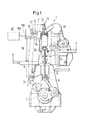
- Fig. 1 shows an embodiment of a large reciprocating piston combustion engine of the diesel type 1 and particularly a two-stroke large reciprocating piston combustion engine of the diesel type according to the present invention.
- the engine 1 typically contains a crankshaft 2 which is rotatably journalled in a crankshaft housing, a plurality of cylinders and a piston 10 each, which is movably arranged in a cylinder liner 11.
- the piston 10 is usually connected to a respective crosshead 8 via a piston rod 9 and the crosshead 8 is connected to the crankshaft 2 via a connecting rod to drive the crankshaft.
- the cylinder liner 11 is upwardly closed by a cylinder cover so that a combustion space 3 is respectively formed in the cylinder between the piston and the cylinder cover.
- the cooperation between the crankshaft 2 and the fuel supply is advantageously controlled electronically by a control unit 20.
- the fuel can e.g. be supplied to an injection nozzle 12 with a high pressure pump 4 via a tube line 6 and via an injection device 7.
- the cooperation between the crankshaft 2 and outlet valve 13 is also controlled electronically by the control unit 20.
- a hydraulic system comprising a pressure pump 14, a tube line 16 and a control valve 17 allows to open and to close the outlet valve 13.
- the control unit 20 is advantageously connected to either or both of the injection device 7 and the control valve 17 via control lines 19a, 19b respectively.
- either or both of the tube line or tube lines 6, 16 can be connected to an optional accumulator 5, 15 respectively.
- the large reciprocating piston combustion engine of the diesel type can optionally include a turbocharger 18 through which the exhaust gas coming from the outlet valve 13 is passed in order to increase the efficiency of the large reciprocating piston combustion engine of the diesel type.
- the large reciprocating piston combustion engine 1 is implemented as a longitudinally scavenged two-stroke diesel engine which has a centrally arranged outlet valve 13 and a plurality of injection nozzles 12 which are arranged peripherally at the cylinder cover.
- a two-stroke diesel engine 1 of this kind has two to four injection nozzles 12 for fuel injection.
- the large reciprocating piston combustion engine of the diesel type 1 includes a system according to the invention for controlling the operation of the engine. This system is explained in detail in connection with the description of Fig. 2 below.
- Fig. 2 shows a schematic view of an embodiment of a system according to the present invention for controlling the operation of a large reciprocating piston combustion engine of the diesel type.
- the system 30 shown includes at least one injection nozzle 32.1, 32.2 for injecting fuel into a combustion chamber 23 of the reciprocating piston combustion engine and a control unit 20 for applying so-called variable injection timing in a partial load range by advancing the value of the injection begin angle depending on engine load or engine speed.
- the system additionally includes a detector 21 for detecting an increase in engine load or engine speed or in the engine load or engine speed setting, wherein the system is configured to compare the detected increase with a predetermined value and to keep the advance in the injection begin angle caused by variable injection timing unchanged or to shift it to zero if the detected increase exceeds the predetermined value, and wherein the system advances the value of the injection begin angle to the value given by variable injection timing under steady state conditions after stabilization of the engine load or engine speed, in particular after a predefined stabilization time between 30 and 60 minutes or longer.
- the detector 21 is advantageously connected to the control unit 20, for example via a line 21 a, and can e.g. be implemented and arranged to detect the angle of the crankshaft 22 or of an axis driven by the crankshaft.
- the system includes injection devices 27.1, 27.2 and a fuel supply including a tube line or tube lines 26 connected to the injection devices.
- the control unit 20 is favorably connected to each of the injection devices 27.1, 27.2 via control lines 29.1, 29.2 respectively.
- the injection devices 27.1, 27.2 are usually connected to the injection nozzles 32.1, 32.2 via feed lines 28.1, 28.2 respectively.
- the injection nozzle or nozzles 32.1, 32.2 of a known type of construction each have a nozzle needle 34.1, 34.2 which is pressed against a seat area by the action of a closing spring 35.1, 35.2. Beneath the seat area a blind hole is arranged in the nozzle housing, from which injection holes 33.1, 33.2 lead into the combustion chamber 23.
- a pressure chamber 31.1, 31.2 is each arranged in the nozzle housing above the seat area and is connected to the feed lines 28.1, 28.2 respectively.
- a line 25 can be connected to the housing of the injection nozzles 32.1, 32.2 for conveying off leakage fuel.
- the method includes injecting fuel into a combustion chamber 3, 23 of the reciprocating piston combustion engine 1 and applying so-called variable injection timing in a partial load range by advancing the value of the injection begin angle depending on engine load or engine speed.
- the method additionally includes detecting an increase in engine load or engine speed, comparing the detected increase with a predetermined value and keeping the advance in the injection begin angle caused by variable injection timing either unchanged or shifting it to zero if the detected increase exceeds the predetermined value, and advancing the value of the injection begin angle to the value given by variable injection timing under steady state conditions after stabilization of the engine load or engine speed, for example after a predefined stabilization time between 30 and 60 minutes or longer.
- the value of the injection begin angle is advantageously advanced with a predetermined ramp up time to the value given by variable injection timing under steady state conditions after stabilization of the engine load or engine speed.
- the advance in the injection begin angle caused by variable injection timing is advantageously shifted to zero with a predetermined ramp down time if the detected increase exceeds the predetermined value.
- the increase in engine load or engine speed is detected in a time interval, in particular a time interval of 10 minutes maximum or 20 minutes maximum or 30 minutes maximum, and wherein the advance in the injection begin angle caused by variable injection timing is kept unchanged or shifted to zero if the detected increase exceeds the predetermined value in this time interval.
- the partial load range in which variable injection timing is applied typically extends from about 60 % to 95 % of full engine load or full engine speed.
- the predetermined value with which the detected increase is compared can e.g. be at least 1.5 % or 2 % of the full engine load or engine speed and can optionally depend on the size of the engine.
- an operator adjustable Fuel Quality Setting is provided for compensating poor fuel ignition properties by advancing or retarding the value of the injection begin angle, for example by a manually input value, and the advance or retard in the injection begin angle caused by Fuel Quality Setting is either kept unchanged or shifted to zero if the detected increase exceeds the predetermined value.
- the advance or retard in the injection begin angle caused by Fuel Quality Setting is shifted to the value it had before the detected increase exceeded the predetermined value.
- Fig. 3 shows an exemplary diagram of the advance ⁇ of the injection begin angle as a function of the engine load P under steady state conditions for a large reciprocating piston combustion engine of the diesel type according to the present invention which is controlled by applying variable injection timing.
- the advance ⁇ of the injection begin angle starts to increase from zero as indicated by the full line 36 to a maximum value which is reached at about 90 % engine load.
- the advance ⁇ of the injection begin angle steeply decreases to zero which is reached above 95 % engine load.
- the value of the injection begin angle is usually advanced manually by a constant value in order to compensate poor fuel ignition properties. Above 50 % engine load the advance ⁇ of the injection begin angle starts to increase from the constant value as indicated by the dashed line 36' to a maximum value which is reached at about 90 % engine load. Above 90 % engine load the advance ⁇ of the injection begin angle steeply decreases to the constant value which is reached above 95 % engine load.
- adjustable Fuel Quality Setting is applied, the advance ⁇ of the injection begin angle is usually just shifted by a constant value compared to the advance ⁇ of the injection begin angle when only variable injection timing is applied.
- Fig. 4A and B show exemplary diagrams of the pressure p comb in the cylinder of a large reciprocating piston combustion engine of the diesel type according to the present invention as a function of the crankshaft angle ⁇ .
- Fig. 4A shows the course 40 of the pressure p comb in the cylinder at partial load without variable injection timing
- Fig. 4B shows the course 40' of the pressure p comb in the cylinder at the same partial load with variable injection timing.
- the maximum of the pressure p comb with variable injection timing is clearly higher than the maximum of the pressure p comb without variable injection timing as can be seen easily when comparing Figures 4A and 4B .
- a tangent 41, 41' each has been drawn to the course 40, 40' of the pressure p comb in the cylinder shown in Figures 4A and 4B .
- the gradients dp comb /d ⁇ characterized by an elevation ⁇ and ⁇ ' describe how fast the combustion pressure p comb rises.
- the combustion pressure p comb rises faster when variable injection timing is applied compared to the rise of the combustion pressure p comb when no variable injection timing is applied.
- Fig. 5A shows an exemplary diagram of the variation of the engine load P for a large reciprocating piston combustion engine of the diesel type according to the present invention as a function of time t.
- the variation of the engine load is within a so called dead band, i.e. the variation is smaller than the width b of the dead band and variable injection timing is applied as e.g. indicated in Fig. 3 .
- the engine load increases and the variation of the engine load exceeds the width b of the dead band.
- the width b of the dead band corresponds to the predetermined value used in the system and method according to the invention, wherein the method includes detecting an increase in engine load, comparing the detected increase with the predetermined value and keeping the advance in the injection begin angle caused by variable injection timing either unchanged or shifting it to zero if the detected increase exceeds the predetermined value, and advancing the value of the injection begin angle to the value given by variable injection timing after stabilization of the engine load or engine speed, for example after a predefined stabilization time between 30 and 60 minutes or longer.
- the engine load starts to stabilize after a certain time, e.g. after 15 minutes.
- Fig. 5B shows an exemplary diagram of the so-called dead band width b of the engine load for a large reciprocating piston combustion engine of the diesel type as a function of the engine load P.
- the width b of the dead band starts, as shown in Fig 5B , at about 50 % engine load with a comparatively high value of typically 5 to 8 % of full engine load and decreases to typically 1.5 to 3 % at 100 % engine load.
- the invention further includes a software for controlling the operation of a large reciprocating piston combustion engine of the diesel type, with the software being stored in or on a memory device.
- the software is capable of controlling the operation of the engine according to one or several of the embodiments or embodiment variants of the method described above.
- the system contains a software as described above which is loaded into the control unit and/or system memory for system operation.
- the invention further includes a retrofit set which contains a control unit for implementing a system according to one or several of the embodiments or embodiment variants described above for controlling the operation of a large reciprocating piston combustion engine of the diesel type.
- the retrofit set is implemented as a modification of a remote control set for controlling the operation of a large reciprocating piston combustion engine of the diesel type.
- the method, software, system and retrofit set according to the invention can in the same way include further control functions such as variable exhaust valve opening and/or variable exhaust valve closing in order to increase the efficiency of the large reciprocating piston combustion engine of the diesel type in a partial load range.
- further control functions can be disabled in the same way as the variable injection timing and the Fuel Quality Setting described above during an increase in engine load or engine speed
- a slightly lower efficiency is achieved when using the method, software, system and retrofit set according to the invention for controlling the operation of a large reciprocating piston combustion engine of the diesel type due to temporarily disabling the variable injection timing, Fuel Quality Setting or other control functions intended for increasing efficiency in a partial load range.
- the temporary disabling of these control functions is, however, short and negligible compared to the whole operation time of the large reciprocating piston combustion engine of the diesel type.
- the method, software, system and retrofit set according to the invention and the large reciprocating piston combustion engine of the diesel type according to the invention have, on the other hand, the advantage that they assist in reducing scuffing and that the service life of piston rings and cylinder liners is increased. Seen from an overall economic point, these advantages clearly outweigh the slightly lower efficiency during engine load up.
Landscapes
- Engineering & Computer Science (AREA)
- Chemical & Material Sciences (AREA)
- Combustion & Propulsion (AREA)
- Mechanical Engineering (AREA)
- General Engineering & Computer Science (AREA)
- Electrical Control Of Air Or Fuel Supplied To Internal-Combustion Engine (AREA)
- Combined Controls Of Internal Combustion Engines (AREA)
Abstract
Description
- The invention relates to a method, a software and a system for controlling the operation of a large reciprocating piston combustion engine of the diesel type according to the preamble of claim 1,
claim 9 andclaim 10 respectively, to a retrofit set for controlling the operation of a large reciprocating piston combustion engine of the diesel type according to the preamble ofclaim 12 and to a large reciprocating piston combustion engine of the diesel type according to the preamble ofclaim 14. - In large reciprocating piston combustion engines of the diesel type and particularly in two-stroke large reciprocating piston combustion engines of the diesel type nozzles are used for injecting fuel into a combustion space which is arranged in each cylinder of the engine. As a rule, the injection timing is optimized to yield maximum efficiency at full load. At partial load the efficiency of the engine usually decreases. In modern large reciprocating piston combustion engines of the diesel type so-called variable injection timing is therefore applied in a partial load range in order to compensate the decrease in efficiency occurring at partial load. In the partial load range in which variable injection timing is applied the value of the injection begin angle is automatically advanced depending on engine load and optionally on the scavenge air pressure.
- In addition, an adjustable Fuel Quality Setting can be provided for compensating poor fuel ignition properties by advancing the value of the injection begin angle.
- In
document EP 0 781 907 A1 a method and an apparatus for operating a self-igniting reciprocating piston combustion engine in a partial load range are described in which at least one state variable or at least two state variables of the reciprocating piston combustion engine are measured with a sensor each and both the start of fuel injection as well as the start of the opening and/or closing of an inlet or exhaust valve are regulated in response to the measured state variables in such a manner that the maximum compression pressure in the combustion chamber as a function of the load in an upper partial load range remains constant or nearly constant. The state variable or state variables can be any of the following variables: turbocharger boost pressure, maximum pressure in the cylinder, pressure at a given crankshaft angle in the cylinder, engine power, rotational speed of the engine, rotational speed of the turbocharger, temperature after the compressor, temperature after the boost air cooler, amount of combustion air, exhaust gas temperature before the turbocharger, exhaust gas temperature after the turbocharger or the amount of fuel. - In large reciprocating piston combustion engines of the diesel type operated on low engine load for a prolonged period of time piston rings could adopt their shape to the specific conditions, i.e. to low combustion pressure and low gas forces. If after such a period of time the engine load is increased, e.g. by accelerating the engine speed, the piston rings might not immediately be able to seal properly, and it might not be possible to maintain an oil film between the piston rings and the cylinder liner. The risk of scuffing between piston rings and cylinder liner is therefore increased during acceleration of engine speed.
- It is an object of the present invention to provide a method, a software, a system and a retrofit set for controlling the operation of a large reciprocating piston combustion engine of the diesel type and to provide a large reciprocating piston combustion engine of the diesel type including such a system or such a retrofit set which assist in reducing scuffing and in increasing service life of piston rings and cylinder liners.
- This object is satisfied in accordance with the invention by the method, the software and the system defined in
claims claim 12 and by the large reciprocating piston combustion engine of the diesel type defined inclaim 14. - The method according to the invention for controlling the operation of a large reciprocating piston combustion engine of the diesel type includes injecting fuel into a combustion chamber of the reciprocating piston combustion engine and applying so-called variable injection timing in a partial load range by advancing the value of the injection begin angle depending on engine load or engine speed. The method additionally includes detecting an increase in engine load or engine speed, comparing the detected increase with a predetermined value and keeping the advance in the injection begin angle caused by variable injection timing either unchanged or shifting it to zero if the detected increase exceeds the predetermined value, and advancing the value of the injection begin angle to the value given by variable injection timing under steady state conditions after stabilization of the engine load or engine speed, for example after a predefined stabilization time between 30 and 60 minutes or longer.
- The value of the injection begin angle is advantageously advanced with a predetermined ramp up time to the value given by variable injection timing under steady state conditions after stabilization of the engine load or engine speed.
- Upon detection of an increase in engine load or engine speed, the advance in the injection begin angle caused by variable injection timing is advantageously shifted to zero with a predetermined ramp down time if the detected increase exceeds the predetermined value.
- The partial load range in which variable injection timing is applied typically extends from about 60 % to 95 % of full engine load or full engine speed.
- In an advantageous embodiment the increase in engine load or engine speed is detected in a time interval, in particular a time interval of 10 minutes maximum or 20 minutes maximum or 30 minutes maximum, and wherein the advance in the injection begin angle caused by variable injection timing is kept unchanged or shifted to zero if the detected increase exceeds the predetermined value in this time interval.
- The predetermined value with which the detected increase is compared can e.g. be at least 1.5 % or 2 % of the full engine load or engine speed and can optionally depend on the engine load and/or on the size of the engine.
- In a further advantageous embodiment of the method an operator adjustable Fuel Quality Setting is provided for compensating poor fuel ignition properties by advancing or retarding the value of the injection begin angle, and the advance or retard in the injection begin angle caused by Fuel Quality Setting is either kept unchanged or shifted to zero if the detected increase exceeds the predetermined value.
- In an advantageous embodiment variant, after stabilization of the engine load or engine speed, in particular after a predefined stabilization time between 30 and 60 minutes or longer, the advance or retard in the injection begin angle caused by Fuel Quality Setting is shifted to the value it had before the detected increase exceeded the predetermined value.
- The invention further includes a software for controlling the operation of a large reciprocating piston combustion engine of the diesel type, with the software being stored in or on a memory device. The software is capable of controlling the operation of the engine according to one or several of the embodiments or embodiment variants of the method described above.
- The system according to the invention for controlling the operation of a large reciprocating piston combustion engine of the diesel type includes an injection nozzle for injecting fuel into a combustion chamber of the reciprocating piston combustion engine and a control unit for applying so-called variable injection timing in a partial load range by advancing the value of the injection begin angle depending on engine load or engine speed. The system additionally includes a detector for detecting an increase in engine load or engine speed or in the engine load or engine speed setting, wherein the system is capable and/or configured to compare the detected increase with a predetermined value and to keep the advance in the injection begin angle caused by variable injection timing unchanged or to shift it to zero if the detected increase exceeds the predetermined value, and wherein the system is capable and/or configured to advance the value of the injection begin angle to the value given by variable injection timing under steady state conditions after stabilization of the engine load or engine speed, in particular after a predefined stabilization time between 30 and 60 minutes or longer.
- In a further advantageous embodiment the system contains a software according to the description given above, wherein the software is loaded into the control unit and/or system memory for system operation.
- The invention further includes a retrofit set which contains a control unit for implementing a system according to one or several of the embodiments or embodiment variants described above for controlling the operation of a large reciprocating piston combustion engine of the diesel type. In an advantageous embodiment variant the retrofit set is implemented as a modification of a remote control set for controlling the operation of a large reciprocating piston combustion engine of the diesel type.
- The large reciprocating piston combustion engine of the diesel type according to the invention includes at least one combustion chamber and a system according one or several of the embodiments or embodiment variants described above or a retrofit set according to one or several of the embodiments or embodiment variants described above for controlling the operation of the reciprocating piston combustion engine.
- The method, software, system and retrofit set according to the invention are suitable for the operation of stationary and mobile two-stroke and four-stroke large reciprocating piston combustion engines of the diesel type, in particular for four-stroke diesel engines with a cylinder bore of greater than 160 mm or greater than 200 mm or for two-stroke diesel engines with a cylinder bore of greater than 270 mm or greater than 300 mm diameter.
- The method, software, system and retrofit set according to the invention and the large reciprocating piston combustion engine of the diesel type according to the invention have the advantage that they reduce the combustion pressure pcomb and the gradient dpcomb/dα, which describes how fast the combustion pressure rises, due to advanced injection begin. This minimizes the combustion pressure impact on the piston rings. The piston rings will have better chances to be properly pressed against the liner wall and to properly seal. Elimination of the variable injection timing effect and optionally of the Fuel Quality Setting effect during engine load up increases the safety margin of piston running also due to the fact that with retarded injection begin angle the energy of the exhaust gases is higher and turbocharger speed, scavenge air pressure and mass flow is consequently increased. Thus, an increase in the maximum temperature of "hot parts" caused by an increased amount of fuel injected for engine load up is avoided or limited by the increased scavenge air flow. Moreover, emissions are reduced during engine load up due to better scavenging of the cylinders.
- The above description of the embodiments and variants serves merely as an example. Further advantageous embodiments can be seen from the dependent claims and the drawing. Moreover, in the context of the present invention, individual features from the described or illustrated embodiments and from the described or illustrated variants can be combined with one another in order to form new embodiments.
- In the following the invention will be explained in more detail with reference to the specific embodiment and with reference to the drawing.
- Fig. 1
- is an embodiment of a large reciprocating piston combustion engine of the diesel type according to the present invention;
- Fig. 2
- is a schematic view of an embodiment of a system for controlling the operation of a large reciprocating piston combustion engine of the diesel type according to the present invention;
- Fig. 3
- is an exemplary diagram of the advance of the injection begin angle as a function of the engine load for a large reciprocating piston combustion engine of the diesel type according to the present invention;
- Fig. 4A,B
- are exemplary diagrams of the pressure in the cylinder of a large reciprocating piston combustion engine of the diesel type according to the present invention as a function of the crankshaft angle, without and with variable injection timing respectively;
- Fig. 5A
- is an exemplary diagram of the variation of the engine load for a large reciprocating piston combustion engine of the diesel type according to the present invention as a function of time; and
- Fig. 5B
- is an exemplary diagram of the so-called "dead band" width of the engine load for a large reciprocating piston combustion engine of the diesel type according to the present invention as a function of the engine load.
-
Fig. 1 shows an embodiment of a large reciprocating piston combustion engine of the diesel type 1 and particularly a two-stroke large reciprocating piston combustion engine of the diesel type according to the present invention. The engine 1 typically contains a crankshaft 2 which is rotatably journalled in a crankshaft housing, a plurality of cylinders and apiston 10 each, which is movably arranged in acylinder liner 11. Thepiston 10 is usually connected to arespective crosshead 8 via apiston rod 9 and thecrosshead 8 is connected to the crankshaft 2 via a connecting rod to drive the crankshaft. Thecylinder liner 11 is upwardly closed by a cylinder cover so that acombustion space 3 is respectively formed in the cylinder between the piston and the cylinder cover. - In the embodiment shown in
Fig. 1 the cooperation between the crankshaft 2 and the fuel supply is advantageously controlled electronically by acontrol unit 20. The fuel can e.g. be supplied to aninjection nozzle 12 with a high pressure pump 4 via atube line 6 and via aninjection device 7. In an advantageous embodiment variant the cooperation between the crankshaft 2 andoutlet valve 13 is also controlled electronically by thecontrol unit 20. A hydraulic system comprising apressure pump 14, atube line 16 and acontrol valve 17 allows to open and to close theoutlet valve 13. Thecontrol unit 20 is advantageously connected to either or both of theinjection device 7 and thecontrol valve 17 viacontrol lines 19a, 19b respectively. Moreover, either or both of the tube line ortube lines optional accumulator - The large reciprocating piston combustion engine of the diesel type can optionally include a
turbocharger 18 through which the exhaust gas coming from theoutlet valve 13 is passed in order to increase the efficiency of the large reciprocating piston combustion engine of the diesel type. - In an advantageous embodiment variant the large reciprocating piston combustion engine 1 is implemented as a longitudinally scavenged two-stroke diesel engine which has a centrally arranged
outlet valve 13 and a plurality ofinjection nozzles 12 which are arranged peripherally at the cylinder cover. Usually a two-stroke diesel engine 1 of this kind has two to fourinjection nozzles 12 for fuel injection. - In addition the large reciprocating piston combustion engine of the diesel type 1 includes a system according to the invention for controlling the operation of the engine. This system is explained in detail in connection with the description of
Fig. 2 below. -
Fig. 2 shows a schematic view of an embodiment of a system according to the present invention for controlling the operation of a large reciprocating piston combustion engine of the diesel type. Thesystem 30 shown includes at least one injection nozzle 32.1, 32.2 for injecting fuel into acombustion chamber 23 of the reciprocating piston combustion engine and acontrol unit 20 for applying so-called variable injection timing in a partial load range by advancing the value of the injection begin angle depending on engine load or engine speed. The system additionally includes a detector 21 for detecting an increase in engine load or engine speed or in the engine load or engine speed setting, wherein the system is configured to compare the detected increase with a predetermined value and to keep the advance in the injection begin angle caused by variable injection timing unchanged or to shift it to zero if the detected increase exceeds the predetermined value, and wherein the system advances the value of the injection begin angle to the value given by variable injection timing under steady state conditions after stabilization of the engine load or engine speed, in particular after a predefined stabilization time between 30 and 60 minutes or longer. - The detector 21 is advantageously connected to the
control unit 20, for example via a line 21 a, and can e.g. be implemented and arranged to detect the angle of thecrankshaft 22 or of an axis driven by the crankshaft. - In an advantageous embodiment variant the system includes injection devices 27.1, 27.2 and a fuel supply including a tube line or
tube lines 26 connected to the injection devices. Thecontrol unit 20 is favorably connected to each of the injection devices 27.1, 27.2 via control lines 29.1, 29.2 respectively. Moreover, the injection devices 27.1, 27.2 are usually connected to the injection nozzles 32.1, 32.2 via feed lines 28.1, 28.2 respectively. - In another advantageous embodiment variant of the system the injection nozzle or nozzles 32.1, 32.2 of a known type of construction each have a nozzle needle 34.1, 34.2 which is pressed against a seat area by the action of a closing spring 35.1, 35.2. Beneath the seat area a blind hole is arranged in the nozzle housing, from which injection holes 33.1, 33.2 lead into the
combustion chamber 23. A pressure chamber 31.1, 31.2 is each arranged in the nozzle housing above the seat area and is connected to the feed lines 28.1, 28.2 respectively. During the injection phase of the injection nozzle 32.1, 32.2 the pressure of the fuel supplied to the pressure chamber 31.1, 31.2 is so great that the closing force of the spring 35.1, 35.2 is overcome and the nozzle needle 34.1, 34.2 is lifted off the seat area so that the fuel is let into the blind hole and is ejected into thecombustion chamber 23 through the injection holes 33.1, 33.2. Aline 25 can be connected to the housing of the injection nozzles 32.1, 32.2 for conveying off leakage fuel. - For better understanding the
piston 10, thecylinder liner 11 and thecylinder cover 11 are schematically indicated inFig. 2 by dashed lines. - An embodiment of the method in accordance with the invention for controlling the operation of a large reciprocating piston combustion engine of the diesel type 1 will be described in the following with reference to
Figures 1 and2 . The method includes injecting fuel into acombustion chamber - The value of the injection begin angle is advantageously advanced with a predetermined ramp up time to the value given by variable injection timing under steady state conditions after stabilization of the engine load or engine speed.
- Upon detection of an increase in engine load or engine speed, the advance in the injection begin angle caused by variable injection timing is advantageously shifted to zero with a predetermined ramp down time if the detected increase exceeds the predetermined value.
- In an advantageous embodiment the increase in engine load or engine speed is detected in a time interval, in particular a time interval of 10 minutes maximum or 20 minutes maximum or 30 minutes maximum, and wherein the advance in the injection begin angle caused by variable injection timing is kept unchanged or shifted to zero if the detected increase exceeds the predetermined value in this time interval.
- The partial load range in which variable injection timing is applied typically extends from about 60 % to 95 % of full engine load or full engine speed. The predetermined value with which the detected increase is compared can e.g. be at least 1.5 % or 2 % of the full engine load or engine speed and can optionally depend on the size of the engine.
- In a further advantageous embodiment of the method an operator adjustable Fuel Quality Setting is provided for compensating poor fuel ignition properties by advancing or retarding the value of the injection begin angle, for example by a manually input value, and the advance or retard in the injection begin angle caused by Fuel Quality Setting is either kept unchanged or shifted to zero if the detected increase exceeds the predetermined value.
- In an advantageous embodiment variant, after stabilization of the engine load or engine speed, in particular after a predefined stabilization time between 30 and 60 minutes or longer, the advance or retard in the injection begin angle caused by Fuel Quality Setting is shifted to the value it had before the detected increase exceeded the predetermined value.
-
Fig. 3 shows an exemplary diagram of the advance Δα of the injection begin angle as a function of the engine load P under steady state conditions for a large reciprocating piston combustion engine of the diesel type according to the present invention which is controlled by applying variable injection timing. Above 50 % engine load the advance Δα of the injection begin angle starts to increase from zero as indicated by thefull line 36 to a maximum value which is reached at about 90 % engine load. Above 90 % engine load the advance Δα of the injection begin angle steeply decreases to zero which is reached above 95 % engine load. - When operator adjustable Fuel Quality Setting is provided the value of the injection begin angle is usually advanced manually by a constant value in order to compensate poor fuel ignition properties. Above 50 % engine load the advance Δα of the injection begin angle starts to increase from the constant value as indicated by the dashed line 36' to a maximum value which is reached at about 90 % engine load. Above 90 % engine load the advance Δα of the injection begin angle steeply decreases to the constant value which is reached above 95 % engine load. When adjustable Fuel Quality Setting is applied, the advance Δα of the injection begin angle is usually just shifted by a constant value compared to the advance Δα of the injection begin angle when only variable injection timing is applied.
-
Fig. 4A and B show exemplary diagrams of the pressure pcomb in the cylinder of a large reciprocating piston combustion engine of the diesel type according to the present invention as a function of the crankshaft angle α.Fig. 4A shows thecourse 40 of the pressure pcomb in the cylinder at partial load without variable injection timing whileFig. 4B shows the course 40' of the pressure pcomb in the cylinder at the same partial load with variable injection timing. The maximum of the pressure pcomb with variable injection timing is clearly higher than the maximum of the pressure pcomb without variable injection timing as can be seen easily when comparingFigures 4A and 4B . - Moreover, a tangent 41, 41' each has been drawn to the
course 40, 40' of the pressure pcomb in the cylinder shown inFigures 4A and 4B . The gradients dpcomb/dα characterized by an elevation ϕ and ϕ' describe how fast the combustion pressure pcomb rises. As can be seen easily when comparingFigures 4A and 4B , the combustion pressure pcomb rises faster when variable injection timing is applied compared to the rise of the combustion pressure pcomb when no variable injection timing is applied. -
Fig. 5A shows an exemplary diagram of the variation of the engine load P for a large reciprocating piston combustion engine of the diesel type according to the present invention as a function of time t. In the first half of the diagram the variation of the engine load is within a so called dead band, i.e. the variation is smaller than the width b of the dead band and variable injection timing is applied as e.g. indicated inFig. 3 . Than the engine load increases and the variation of the engine load exceeds the width b of the dead band. - In an advantageous embodiment the width b of the dead band corresponds to the predetermined value used in the system and method according to the invention, wherein the method includes detecting an increase in engine load, comparing the detected increase with the predetermined value and keeping the advance in the injection begin angle caused by variable injection timing either unchanged or shifting it to zero if the detected increase exceeds the predetermined value, and advancing the value of the injection begin angle to the value given by variable injection timing after stabilization of the engine load or engine speed, for example after a predefined stabilization time between 30 and 60 minutes or longer.
- As shown in
Fig. 5A the engine load starts to stabilize after a certain time, e.g. after 15 minutes. -
Fig. 5B shows an exemplary diagram of the so-called dead band width b of the engine load for a large reciprocating piston combustion engine of the diesel type as a function of the engine load P. The width b of the dead band starts, as shown inFig 5B , at about 50 % engine load with a comparatively high value of typically 5 to 8 % of full engine load and decreases to typically 1.5 to 3 % at 100 % engine load. - The invention further includes a software for controlling the operation of a large reciprocating piston combustion engine of the diesel type, with the software being stored in or on a memory device. The software is capable of controlling the operation of the engine according to one or several of the embodiments or embodiment variants of the method described above.
- In a further advantageous embodiment of the system, the system contains a software as described above which is loaded into the control unit and/or system memory for system operation.
- The invention further includes a retrofit set which contains a control unit for implementing a system according to one or several of the embodiments or embodiment variants described above for controlling the operation of a large reciprocating piston combustion engine of the diesel type. In an advantageous embodiment variant the retrofit set is implemented as a modification of a remote control set for controlling the operation of a large reciprocating piston combustion engine of the diesel type.
- The method, software, system and retrofit set according to the invention can in the same way include further control functions such as variable exhaust valve opening and/or variable exhaust valve closing in order to increase the efficiency of the large reciprocating piston combustion engine of the diesel type in a partial load range. These further control functions can be disabled in the same way as the variable injection timing and the Fuel Quality Setting described above during an increase in engine load or engine speed
- During an increase in engine load or engine speed a slightly lower efficiency is achieved when using the method, software, system and retrofit set according to the invention for controlling the operation of a large reciprocating piston combustion engine of the diesel type due to temporarily disabling the variable injection timing, Fuel Quality Setting or other control functions intended for increasing efficiency in a partial load range. The temporary disabling of these control functions is, however, short and negligible compared to the whole operation time of the large reciprocating piston combustion engine of the diesel type. The method, software, system and retrofit set according to the invention and the large reciprocating piston combustion engine of the diesel type according to the invention have, on the other hand, the advantage that they assist in reducing scuffing and that the service life of piston rings and cylinder liners is increased. Seen from an overall economic point, these advantages clearly outweigh the slightly lower efficiency during engine load up.
Claims (14)
- Method for controlling the operation of a large reciprocating piston combustion engine (1) of the diesel type, said method including injecting fuel into a combustion chamber (3, 23) of the reciprocating piston combustion engine and applying so-called variable injection timing in a partial load range by advancing the value of the injection begin angle depending on engine load or engine speed, characterized in that an increase in engine load or engine speed is detected, in that the detected increase is compared with a predetermined value, in that the advance in the injection begin angle caused by variable injection timing is either kept unchanged or shifted to zero if the detected increase exceeds the predetermined value, and in that the value of the injection begin angle is advanced to the value given by variable injection timing under steady state conditions after stabilization of the engine load or engine speed, in particular after a predefined stabilization time between 30 and 60 minutes or longer.
- Method according to claim 1, wherein the increase in engine load or engine speed is detected in a time interval, in particular a time interval of 10 minutes maximum or 20 minutes maximum or 30 minutes maximum, and wherein the advance in the injection begin angle caused by variable injection timing is kept unchanged or shifted to zero if the detected increase exceeds the predetermined value in this time interval.
- Method according to claim 1 or 2, wherein the partial load range in which variable injection timing is applied extends from about 60 % to 95 % of full engine load or full engine speed.
- Method according to any of claims 1 to 3, wherein, upon detection of an increase in engine load or engine speed, the advance in the injection begin angle caused by variable injection timing is shifted to zero with a predetermined ramp down time if the detected increase exceeds the predetermined value.
- Method according to any of claims 2 to 4, wherein the value of the injection begin angle is advanced with a predetermined ramp up time to the value given by variable injection timing under steady state conditions after stabilization of the engine load or engine speed.
- Method according to one of the preceding claims, wherein the predetermined value with which the detected increase is compared is at least 1.5 % or 2 % of the full engine load or engine speed and in particular depends on the size of the engine.
- Method according to one of the preceding claims, wherein an operator adjustable Fuel Quality Setting is provided for compensating poor fuel ignition properties by advancing or retarding the value of the injection begin angle, and wherein the advance or retard in the injection begin angle caused by Fuel Quality Setting is either kept unchanged or shifted to zero if the detected increase exceeds the predetermined value.
- Method according to claim 7, wherein after stabilization of the engine load or engine speed, in particular after a predefined stabilization time between 30 and 60 minutes or longer, the advance or retard in the injection begin angle caused by Fuel Quality Setting is shifted to the value it had before the detected increase exceeded the predetermined value.
- Software for controlling the operation of a large reciprocating piston combustion engine (1) of the diesel type, with the software being stored in or on a memory device, characterized in that the software is capable of controlling the operation of the engine according to a method as defined in any of the claims 1 to 8.
- System (30) for controlling the operation of a large reciprocating piston combustion engine (1) of the diesel type, said system including an injection nozzle (12, 32.1, 32.2) for injecting fuel into a combustion chamber (2, 23) of the reciprocating piston combustion engine and a control unit (20) for applying so-called variable injection timing in a partial load range by advancing the value of the injection begin angle depending on engine load or engine speed, characterized in that the system (30) includes a detector (21) for detecting an increase in engine load or engine speed or in the engine load or engine speed setting, in that the system is configured to compare the detected increase with a predetermined value and to keep the advance in the injection begin angle caused by variable injection timing either unchanged or to shift it to zero if the detected increase exceeds the predetermined value, and in that the system (30) is configured to advance the value of the injection begin angle to the value given by variable injection timing under steady state conditions after stabilization of the engine load or engine speed, in particular after a predefined stabilization time between 30 and 60 minutes or longer.
- System according to claim 10 containing a software according to claim 9, with the software being loaded into the control unit and/or system memory for system operation.
- Retrofit set containing a control unit for implementing a system according to any of the claims 10 or 11 for controlling the operation of a large reciprocating piston combustion engine of the diesel type.
- Retrofit set according to claim 12 implemented as a modification of a remote control set for controlling the operation of a large reciprocating piston combustion engine of the diesel type.
- Large reciprocating piston combustion engine (1) of the diesel type including at least one combustion chamber (3, 23) and a system (30) according to any of claims 9 or 10 or a retrofit set according to claims 12 or 13 for controlling the operation of the reciprocating piston combustion engine.
Priority Applications (1)
| Application Number | Priority Date | Filing Date | Title |
|---|---|---|---|
| EP12171599.9A EP2565432B8 (en) | 2011-07-14 | 2012-06-12 | Fuel injection timing control for a large reciprocating piston combustion engine |
Applications Claiming Priority (2)
| Application Number | Priority Date | Filing Date | Title |
|---|---|---|---|
| EP11173956 | 2011-07-14 | ||
| EP12171599.9A EP2565432B8 (en) | 2011-07-14 | 2012-06-12 | Fuel injection timing control for a large reciprocating piston combustion engine |
Publications (4)
| Publication Number | Publication Date |
|---|---|
| EP2565432A2 true EP2565432A2 (en) | 2013-03-06 |
| EP2565432A3 EP2565432A3 (en) | 2018-07-04 |
| EP2565432B1 EP2565432B1 (en) | 2024-07-03 |
| EP2565432B8 EP2565432B8 (en) | 2024-08-14 |
Family
ID=46197197
Family Applications (1)
| Application Number | Title | Priority Date | Filing Date |
|---|---|---|---|
| EP12171599.9A Active EP2565432B8 (en) | 2011-07-14 | 2012-06-12 | Fuel injection timing control for a large reciprocating piston combustion engine |
Country Status (5)
| Country | Link |
|---|---|
| EP (1) | EP2565432B8 (en) |
| JP (2) | JP2013024237A (en) |
| KR (1) | KR102090831B1 (en) |
| CN (1) | CN102877973B (en) |
| DK (1) | DK2565432T3 (en) |
Cited By (1)
| Publication number | Priority date | Publication date | Assignee | Title |
|---|---|---|---|---|
| CN115030831A (en) * | 2021-03-03 | 2022-09-09 | 北汽福田汽车股份有限公司 | Engine control method, computer-readable storage medium, and vehicle |
Citations (1)
| Publication number | Priority date | Publication date | Assignee | Title |
|---|---|---|---|---|
| EP0781907A1 (en) | 1995-12-27 | 1997-07-02 | New Sulzer Diesel Ag | Method and device for operating an auto-igniting piston engine |
Family Cites Families (18)
| Publication number | Priority date | Publication date | Assignee | Title |
|---|---|---|---|---|
| JPS5799238A (en) * | 1980-12-11 | 1982-06-19 | Kawasaki Heavy Ind Ltd | Method of controlling the fuel to diesel engine and the control device |
| JPS5910746A (en) * | 1982-07-08 | 1984-01-20 | Toyota Motor Corp | Method of controlling fuel injection timing in diesel engine |
| JPH01159445A (en) * | 1987-12-16 | 1989-06-22 | Nippon Denso Co Ltd | Diesel engine controller |
| JPH08121231A (en) * | 1994-10-26 | 1996-05-14 | Nissan Motor Co Ltd | Control device for fuel injection pump of diesel engine |
| DE19646942A1 (en) * | 1996-11-13 | 1998-05-14 | Bayerische Motoren Werke Ag | Fuel injection device for an air-compressing internal combustion engine |
| KR100287703B1 (en) * | 1996-12-31 | 2001-05-02 | 이계안 | Compensating device for timer advancing of diesel engine |
| DE69930181T2 (en) * | 1998-08-21 | 2006-11-23 | Toyota Jidosha K.K., Toyota | Internal combustion engine |
| US6325044B1 (en) * | 1999-05-07 | 2001-12-04 | General Electric Company | Apparatus and method for suppressing diesel engine emissions |
| DE19937139C1 (en) * | 1999-08-06 | 2001-04-05 | Mtu Friedrichshafen Gmbh | Combustion engine control method and device detects significant variation in engine loading for delaying fuel injection timing for assisting rev regulation |
| JP2001241345A (en) * | 2000-02-29 | 2001-09-07 | Mazda Motor Corp | Diesel engine fuel control system |
| JP2003138952A (en) * | 2001-11-05 | 2003-05-14 | Mitsubishi Motors Corp | Diesel engine |
| US6857418B2 (en) * | 2002-10-15 | 2005-02-22 | International Engine Intellectual Property Company, Llc | Fuel injection timing compensation based on engine load |
| JP2004239230A (en) * | 2003-02-10 | 2004-08-26 | Nissan Motor Co Ltd | Combustion control device for internal combustion engine |
| JP2004239229A (en) * | 2003-02-10 | 2004-08-26 | Nissan Motor Co Ltd | Fuel property determination device for internal combustion engine |
| US6968830B2 (en) * | 2003-12-30 | 2005-11-29 | General Electric Company | Apparatus and method for suppressing internal combustion ignition engine emissions |
| GB2423119B (en) * | 2005-08-05 | 2007-08-08 | Scion Sprays Ltd | A Fuel injection system for an internal combustion engine |
| JP4479822B2 (en) * | 2008-04-21 | 2010-06-09 | トヨタ自動車株式会社 | In-cylinder injection spark ignition internal combustion engine |
| US9328690B2 (en) * | 2010-10-01 | 2016-05-03 | GM Global Technology Operations LLC | System and method for controlling fuel injection timing to decrease emissions during transient engine operation |
-
2012
- 2012-06-12 DK DK12171599.9T patent/DK2565432T3/en active
- 2012-06-12 EP EP12171599.9A patent/EP2565432B8/en active Active
- 2012-07-02 JP JP2012148814A patent/JP2013024237A/en active Pending
- 2012-07-11 CN CN201210240183.5A patent/CN102877973B/en active Active
- 2012-07-13 KR KR1020120076710A patent/KR102090831B1/en active Active
-
2018
- 2018-07-02 JP JP2018126406A patent/JP2018145972A/en active Pending
Patent Citations (1)
| Publication number | Priority date | Publication date | Assignee | Title |
|---|---|---|---|---|
| EP0781907A1 (en) | 1995-12-27 | 1997-07-02 | New Sulzer Diesel Ag | Method and device for operating an auto-igniting piston engine |
Cited By (2)
| Publication number | Priority date | Publication date | Assignee | Title |
|---|---|---|---|---|
| CN115030831A (en) * | 2021-03-03 | 2022-09-09 | 北汽福田汽车股份有限公司 | Engine control method, computer-readable storage medium, and vehicle |
| CN115030831B (en) * | 2021-03-03 | 2023-10-03 | 北汽福田汽车股份有限公司 | Engine control method, computer-readable storage medium, and vehicle |
Also Published As
| Publication number | Publication date |
|---|---|
| CN102877973A (en) | 2013-01-16 |
| CN102877973B (en) | 2017-05-17 |
| JP2013024237A (en) | 2013-02-04 |
| JP2018145972A (en) | 2018-09-20 |
| EP2565432B1 (en) | 2024-07-03 |
| KR102090831B1 (en) | 2020-03-19 |
| EP2565432A3 (en) | 2018-07-04 |
| DK2565432T3 (en) | 2024-09-23 |
| EP2565432B8 (en) | 2024-08-14 |
| KR20130009696A (en) | 2013-01-23 |
Similar Documents
| Publication | Publication Date | Title |
|---|---|---|
| CN105569864B (en) | Method for controlling combustion in an internal combustion engine and internal combustion engine | |
| US8949002B2 (en) | System and method for injecting fuel | |
| US10024246B2 (en) | Method for controlling an engine braking device and engine braking device | |
| RU2718383C2 (en) | Method and system for motor control | |
| CN110462187B (en) | Method and system for engine skip fire | |
| US9732713B2 (en) | Purge system for a dual-fuel engine | |
| RU2721745C2 (en) | Engine operating parameter control method (versions) and corresponding system | |
| RU152674U1 (en) | ENGINE SYSTEM | |
| CN102022209A (en) | Injection method and device for controlling an injection process in an internal combustion engine | |
| US7735465B2 (en) | Method for operating an internal combustion engine | |
| WO2014077002A1 (en) | Diesel engine control device, diesel engine, and diesel engine control method | |
| RU2640882C2 (en) | Engine operation method (versions) and engine control system | |
| KR102603855B1 (en) | Method of operating a piston engine and control system for a piston engine | |
| EP2565432B1 (en) | Fuel injection timing control for a large reciprocating piston combustion engine | |
| EP3336337A1 (en) | Method of operating a gaseous fuel internal combustion engine | |
| US10767581B2 (en) | Method for operating an internal combustion engine for a motor vehicle, and a system for an internal combustion engine | |
| US20090164103A1 (en) | Fuel injection control device for engine | |
| EP3140535B1 (en) | Method in controlling a dual fuel engine | |
| US8613272B2 (en) | Spark-ignited gas engine | |
| KR102656103B1 (en) | A large two-stroke uniflow scavenged gaseous fueled engine and method for controlling supply of liquid fuel | |
| WO2019124431A1 (en) | Compression-end pressure control device and engine system | |
| JP5786468B2 (en) | Control device for internal combustion engine | |
| EP2902607A1 (en) | Cylinder injection engine control apparatus | |
| JP4135254B2 (en) | Fuel injection device for internal combustion engine | |
| KR102638479B1 (en) | Method in 2-stroke engine and 2-stroke engine |
Legal Events
| Date | Code | Title | Description |
|---|---|---|---|
| PUAI | Public reference made under article 153(3) epc to a published international application that has entered the european phase |
Free format text: ORIGINAL CODE: 0009012 |
|
| AK | Designated contracting states |
Kind code of ref document: A2 Designated state(s): AL AT BE BG CH CY CZ DE DK EE ES FI FR GB GR HR HU IE IS IT LI LT LU LV MC MK MT NL NO PL PT RO RS SE SI SK SM TR |
|
| AX | Request for extension of the european patent |
Extension state: BA ME |
|
| RIC1 | Information provided on ipc code assigned before grant |
Ipc: F02B 25/04 20060101ALN20180416BHEP Ipc: F02B 3/06 20060101ALN20180416BHEP Ipc: F02D 19/06 20060101ALI20180416BHEP Ipc: F02D 41/04 20060101ALI20180416BHEP Ipc: F02B 75/02 20060101ALN20180416BHEP Ipc: F02D 41/00 20060101ALI20180416BHEP Ipc: F02D 41/40 20060101AFI20180416BHEP Ipc: F02D 41/38 20060101ALN20180416BHEP |
|
| PUAL | Search report despatched |
Free format text: ORIGINAL CODE: 0009013 |
|
| AK | Designated contracting states |
Kind code of ref document: A3 Designated state(s): AL AT BE BG CH CY CZ DE DK EE ES FI FR GB GR HR HU IE IS IT LI LT LU LV MC MK MT NL NO PL PT RO RS SE SI SK SM TR |
|
| AX | Request for extension of the european patent |
Extension state: BA ME |
|
| STAA | Information on the status of an ep patent application or granted ep patent |
Free format text: STATUS: REQUEST FOR EXAMINATION WAS MADE |
|
| 17P | Request for examination filed |
Effective date: 20190104 |
|
| RBV | Designated contracting states (corrected) |
Designated state(s): AL AT BE BG CH CY CZ DE DK EE ES FI FR GB GR HR HU IE IS IT LI LT LU LV MC MK MT NL NO PL PT RO RS SE SI SK SM TR |
|
| STAA | Information on the status of an ep patent application or granted ep patent |
Free format text: STATUS: EXAMINATION IS IN PROGRESS |
|
| 17Q | First examination report despatched |
Effective date: 20200323 |
|
| GRAP | Despatch of communication of intention to grant a patent |
Free format text: ORIGINAL CODE: EPIDOSNIGR1 |
|
| STAA | Information on the status of an ep patent application or granted ep patent |
Free format text: STATUS: GRANT OF PATENT IS INTENDED |
|
| RIC1 | Information provided on ipc code assigned before grant |
Ipc: F02D 41/38 20060101ALN20240318BHEP Ipc: F02B 75/02 20060101ALN20240318BHEP Ipc: F02B 25/04 20060101ALN20240318BHEP Ipc: F02B 3/06 20060101ALN20240318BHEP Ipc: F02D 41/04 20060101ALI20240318BHEP Ipc: F02D 41/00 20060101ALI20240318BHEP Ipc: F02D 19/06 20060101ALI20240318BHEP Ipc: F02D 41/40 20060101AFI20240318BHEP |
|
| INTG | Intention to grant announced |
Effective date: 20240408 |
|
| GRAS | Grant fee paid |
Free format text: ORIGINAL CODE: EPIDOSNIGR3 |
|
| GRAA | (expected) grant |
Free format text: ORIGINAL CODE: 0009210 |
|
| STAA | Information on the status of an ep patent application or granted ep patent |
Free format text: STATUS: THE PATENT HAS BEEN GRANTED |
|
| AK | Designated contracting states |
Kind code of ref document: B1 Designated state(s): AL AT BE BG CH CY CZ DE DK EE ES FI FR GB GR HR HU IE IS IT LI LT LU LV MC MK MT NL NO PL PT RO RS SE SI SK SM TR |
|
| REG | Reference to a national code |
Ref country code: CH Ref legal event code: EP |
|
| REG | Reference to a national code |
Ref country code: DE Ref legal event code: R096 Ref document number: 602012080912 Country of ref document: DE |
|
| RAP4 | Party data changed (patent owner data changed or rights of a patent transferred) |
Owner name: WINGD AG |
|
| REG | Reference to a national code |
Ref country code: CH Ref legal event code: PK Free format text: BERICHTIGUNG B8 |
|
| REG | Reference to a national code |
Ref country code: DK Ref legal event code: T3 Effective date: 20240920 |
|
| REG | Reference to a national code |
Ref country code: LT Ref legal event code: MG9D |
|
| REG | Reference to a national code |
Ref country code: NL Ref legal event code: MP Effective date: 20240703 |
|
| PG25 | Lapsed in a contracting state [announced via postgrant information from national office to epo] |
Ref country code: PT Free format text: LAPSE BECAUSE OF FAILURE TO SUBMIT A TRANSLATION OF THE DESCRIPTION OR TO PAY THE FEE WITHIN THE PRESCRIBED TIME-LIMIT Effective date: 20241104 |
|
| REG | Reference to a national code |
Ref country code: AT Ref legal event code: MK05 Ref document number: 1700044 Country of ref document: AT Kind code of ref document: T Effective date: 20240703 |
|
| PG25 | Lapsed in a contracting state [announced via postgrant information from national office to epo] |
Ref country code: NL Free format text: LAPSE BECAUSE OF FAILURE TO SUBMIT A TRANSLATION OF THE DESCRIPTION OR TO PAY THE FEE WITHIN THE PRESCRIBED TIME-LIMIT Effective date: 20240703 |
|
| PG25 | Lapsed in a contracting state [announced via postgrant information from national office to epo] |
Ref country code: PT Free format text: LAPSE BECAUSE OF FAILURE TO SUBMIT A TRANSLATION OF THE DESCRIPTION OR TO PAY THE FEE WITHIN THE PRESCRIBED TIME-LIMIT Effective date: 20241104 Ref country code: NL Free format text: LAPSE BECAUSE OF FAILURE TO SUBMIT A TRANSLATION OF THE DESCRIPTION OR TO PAY THE FEE WITHIN THE PRESCRIBED TIME-LIMIT Effective date: 20240703 |
|
| PG25 | Lapsed in a contracting state [announced via postgrant information from national office to epo] |
Ref country code: NO Free format text: LAPSE BECAUSE OF FAILURE TO SUBMIT A TRANSLATION OF THE DESCRIPTION OR TO PAY THE FEE WITHIN THE PRESCRIBED TIME-LIMIT Effective date: 20241003 |
|
| PG25 | Lapsed in a contracting state [announced via postgrant information from national office to epo] |
Ref country code: PL Free format text: LAPSE BECAUSE OF FAILURE TO SUBMIT A TRANSLATION OF THE DESCRIPTION OR TO PAY THE FEE WITHIN THE PRESCRIBED TIME-LIMIT Effective date: 20240703 Ref country code: GR Free format text: LAPSE BECAUSE OF FAILURE TO SUBMIT A TRANSLATION OF THE DESCRIPTION OR TO PAY THE FEE WITHIN THE PRESCRIBED TIME-LIMIT Effective date: 20241004 Ref country code: FI Free format text: LAPSE BECAUSE OF FAILURE TO SUBMIT A TRANSLATION OF THE DESCRIPTION OR TO PAY THE FEE WITHIN THE PRESCRIBED TIME-LIMIT Effective date: 20240703 |
|
| PG25 | Lapsed in a contracting state [announced via postgrant information from national office to epo] |
Ref country code: BG Free format text: LAPSE BECAUSE OF FAILURE TO SUBMIT A TRANSLATION OF THE DESCRIPTION OR TO PAY THE FEE WITHIN THE PRESCRIBED TIME-LIMIT Effective date: 20240703 |
|
| PG25 | Lapsed in a contracting state [announced via postgrant information from national office to epo] |
Ref country code: LV Free format text: LAPSE BECAUSE OF FAILURE TO SUBMIT A TRANSLATION OF THE DESCRIPTION OR TO PAY THE FEE WITHIN THE PRESCRIBED TIME-LIMIT Effective date: 20240703 |
|
| PG25 | Lapsed in a contracting state [announced via postgrant information from national office to epo] |
Ref country code: IS Free format text: LAPSE BECAUSE OF FAILURE TO SUBMIT A TRANSLATION OF THE DESCRIPTION OR TO PAY THE FEE WITHIN THE PRESCRIBED TIME-LIMIT Effective date: 20241103 Ref country code: AT Free format text: LAPSE BECAUSE OF FAILURE TO SUBMIT A TRANSLATION OF THE DESCRIPTION OR TO PAY THE FEE WITHIN THE PRESCRIBED TIME-LIMIT Effective date: 20240703 |
|
| PG25 | Lapsed in a contracting state [announced via postgrant information from national office to epo] |
Ref country code: HR Free format text: LAPSE BECAUSE OF FAILURE TO SUBMIT A TRANSLATION OF THE DESCRIPTION OR TO PAY THE FEE WITHIN THE PRESCRIBED TIME-LIMIT Effective date: 20240703 Ref country code: CZ Free format text: LAPSE BECAUSE OF FAILURE TO SUBMIT A TRANSLATION OF THE DESCRIPTION OR TO PAY THE FEE WITHIN THE PRESCRIBED TIME-LIMIT Effective date: 20240703 |
|
| PG25 | Lapsed in a contracting state [announced via postgrant information from national office to epo] |
Ref country code: RS Free format text: LAPSE BECAUSE OF FAILURE TO SUBMIT A TRANSLATION OF THE DESCRIPTION OR TO PAY THE FEE WITHIN THE PRESCRIBED TIME-LIMIT Effective date: 20241003 Ref country code: ES Free format text: LAPSE BECAUSE OF FAILURE TO SUBMIT A TRANSLATION OF THE DESCRIPTION OR TO PAY THE FEE WITHIN THE PRESCRIBED TIME-LIMIT Effective date: 20240703 |
|
| PG25 | Lapsed in a contracting state [announced via postgrant information from national office to epo] |
Ref country code: RS Free format text: LAPSE BECAUSE OF FAILURE TO SUBMIT A TRANSLATION OF THE DESCRIPTION OR TO PAY THE FEE WITHIN THE PRESCRIBED TIME-LIMIT Effective date: 20241003 Ref country code: PL Free format text: LAPSE BECAUSE OF FAILURE TO SUBMIT A TRANSLATION OF THE DESCRIPTION OR TO PAY THE FEE WITHIN THE PRESCRIBED TIME-LIMIT Effective date: 20240703 Ref country code: NO Free format text: LAPSE BECAUSE OF FAILURE TO SUBMIT A TRANSLATION OF THE DESCRIPTION OR TO PAY THE FEE WITHIN THE PRESCRIBED TIME-LIMIT Effective date: 20241003 Ref country code: LV Free format text: LAPSE BECAUSE OF FAILURE TO SUBMIT A TRANSLATION OF THE DESCRIPTION OR TO PAY THE FEE WITHIN THE PRESCRIBED TIME-LIMIT Effective date: 20240703 Ref country code: IS Free format text: LAPSE BECAUSE OF FAILURE TO SUBMIT A TRANSLATION OF THE DESCRIPTION OR TO PAY THE FEE WITHIN THE PRESCRIBED TIME-LIMIT Effective date: 20241103 Ref country code: HR Free format text: LAPSE BECAUSE OF FAILURE TO SUBMIT A TRANSLATION OF THE DESCRIPTION OR TO PAY THE FEE WITHIN THE PRESCRIBED TIME-LIMIT Effective date: 20240703 Ref country code: GR Free format text: LAPSE BECAUSE OF FAILURE TO SUBMIT A TRANSLATION OF THE DESCRIPTION OR TO PAY THE FEE WITHIN THE PRESCRIBED TIME-LIMIT Effective date: 20241004 Ref country code: FI Free format text: LAPSE BECAUSE OF FAILURE TO SUBMIT A TRANSLATION OF THE DESCRIPTION OR TO PAY THE FEE WITHIN THE PRESCRIBED TIME-LIMIT Effective date: 20240703 Ref country code: ES Free format text: LAPSE BECAUSE OF FAILURE TO SUBMIT A TRANSLATION OF THE DESCRIPTION OR TO PAY THE FEE WITHIN THE PRESCRIBED TIME-LIMIT Effective date: 20240703 Ref country code: CZ Free format text: LAPSE BECAUSE OF FAILURE TO SUBMIT A TRANSLATION OF THE DESCRIPTION OR TO PAY THE FEE WITHIN THE PRESCRIBED TIME-LIMIT Effective date: 20240703 Ref country code: BG Free format text: LAPSE BECAUSE OF FAILURE TO SUBMIT A TRANSLATION OF THE DESCRIPTION OR TO PAY THE FEE WITHIN THE PRESCRIBED TIME-LIMIT Effective date: 20240703 Ref country code: AT Free format text: LAPSE BECAUSE OF FAILURE TO SUBMIT A TRANSLATION OF THE DESCRIPTION OR TO PAY THE FEE WITHIN THE PRESCRIBED TIME-LIMIT Effective date: 20240703 |
|
| REG | Reference to a national code |
Ref country code: DE Ref legal event code: R097 Ref document number: 602012080912 Country of ref document: DE |
|
| PG25 | Lapsed in a contracting state [announced via postgrant information from national office to epo] |
Ref country code: RO Free format text: LAPSE BECAUSE OF FAILURE TO SUBMIT A TRANSLATION OF THE DESCRIPTION OR TO PAY THE FEE WITHIN THE PRESCRIBED TIME-LIMIT Effective date: 20240703 Ref country code: SM Free format text: LAPSE BECAUSE OF FAILURE TO SUBMIT A TRANSLATION OF THE DESCRIPTION OR TO PAY THE FEE WITHIN THE PRESCRIBED TIME-LIMIT Effective date: 20240703 |
|
| PG25 | Lapsed in a contracting state [announced via postgrant information from national office to epo] |
Ref country code: IT Free format text: LAPSE BECAUSE OF FAILURE TO SUBMIT A TRANSLATION OF THE DESCRIPTION OR TO PAY THE FEE WITHIN THE PRESCRIBED TIME-LIMIT Effective date: 20240703 Ref country code: SK Free format text: LAPSE BECAUSE OF FAILURE TO SUBMIT A TRANSLATION OF THE DESCRIPTION OR TO PAY THE FEE WITHIN THE PRESCRIBED TIME-LIMIT Effective date: 20240703 |
|
| PLBE | No opposition filed within time limit |
Free format text: ORIGINAL CODE: 0009261 |
|
| STAA | Information on the status of an ep patent application or granted ep patent |
Free format text: STATUS: NO OPPOSITION FILED WITHIN TIME LIMIT |
|
| 26N | No opposition filed |
Effective date: 20250404 |
|
| PGFP | Annual fee paid to national office [announced via postgrant information from national office to epo] |
Ref country code: DE Payment date: 20250618 Year of fee payment: 14 |
|
| PGFP | Annual fee paid to national office [announced via postgrant information from national office to epo] |
Ref country code: DK Payment date: 20250625 Year of fee payment: 14 |
|
| REG | Reference to a national code |
Ref country code: DE Ref legal event code: R081 Ref document number: 602012080912 Country of ref document: DE Owner name: WINGD AG, CH Free format text: FORMER OWNER: WAERTSILAE SCHWEIZ AG, WINTERTHUR, CH |
|
| PG25 | Lapsed in a contracting state [announced via postgrant information from national office to epo] |
Ref country code: SE Free format text: LAPSE BECAUSE OF FAILURE TO SUBMIT A TRANSLATION OF THE DESCRIPTION OR TO PAY THE FEE WITHIN THE PRESCRIBED TIME-LIMIT Effective date: 20240703 |
|
| REG | Reference to a national code |
Ref country code: CH Ref legal event code: H13 Free format text: ST27 STATUS EVENT CODE: U-0-0-H10-H13 (AS PROVIDED BY THE NATIONAL OFFICE) Effective date: 20260127 |
|
| PG25 | Lapsed in a contracting state [announced via postgrant information from national office to epo] |
Ref country code: MC Free format text: LAPSE BECAUSE OF FAILURE TO SUBMIT A TRANSLATION OF THE DESCRIPTION OR TO PAY THE FEE WITHIN THE PRESCRIBED TIME-LIMIT Effective date: 20240703 |
|
| PG25 | Lapsed in a contracting state [announced via postgrant information from national office to epo] |
Ref country code: LU Free format text: LAPSE BECAUSE OF NON-PAYMENT OF DUE FEES Effective date: 20250612 |
|
| GBPC | Gb: european patent ceased through non-payment of renewal fee |
Effective date: 20250612 |
|
| REG | Reference to a national code |
Ref country code: BE Ref legal event code: MM Effective date: 20250630 |
|
| PG25 | Lapsed in a contracting state [announced via postgrant information from national office to epo] |
Ref country code: GB Free format text: LAPSE BECAUSE OF NON-PAYMENT OF DUE FEES Effective date: 20250612 |
|
| PG25 | Lapsed in a contracting state [announced via postgrant information from national office to epo] |
Ref country code: IE Free format text: LAPSE BECAUSE OF NON-PAYMENT OF DUE FEES Effective date: 20250612 |
|
| PG25 | Lapsed in a contracting state [announced via postgrant information from national office to epo] |
Ref country code: BE Free format text: LAPSE BECAUSE OF NON-PAYMENT OF DUE FEES Effective date: 20250630 |
|
| PG25 | Lapsed in a contracting state [announced via postgrant information from national office to epo] |
Ref country code: FR Free format text: LAPSE BECAUSE OF NON-PAYMENT OF DUE FEES Effective date: 20250630 |
|
| PG25 | Lapsed in a contracting state [announced via postgrant information from national office to epo] |
Ref country code: CH Free format text: LAPSE BECAUSE OF NON-PAYMENT OF DUE FEES Effective date: 20250630 |