EP2565420A2 - Accessory gearbox device for a turbine engine - Google Patents
Accessory gearbox device for a turbine engine Download PDFInfo
- Publication number
- EP2565420A2 EP2565420A2 EP12181534A EP12181534A EP2565420A2 EP 2565420 A2 EP2565420 A2 EP 2565420A2 EP 12181534 A EP12181534 A EP 12181534A EP 12181534 A EP12181534 A EP 12181534A EP 2565420 A2 EP2565420 A2 EP 2565420A2
- Authority
- EP
- European Patent Office
- Prior art keywords
- generator
- shaft
- auxiliary
- transmission device
- region
- Prior art date
- Legal status (The legal status is an assumption and is not a legal conclusion. Google has not performed a legal analysis and makes no representation as to the accuracy of the status listed.)
- Withdrawn
Links
Images

Classifications
-
- F—MECHANICAL ENGINEERING; LIGHTING; HEATING; WEAPONS; BLASTING
- F02—COMBUSTION ENGINES; HOT-GAS OR COMBUSTION-PRODUCT ENGINE PLANTS
- F02C—GAS-TURBINE PLANTS; AIR INTAKES FOR JET-PROPULSION PLANTS; CONTROLLING FUEL SUPPLY IN AIR-BREATHING JET-PROPULSION PLANTS
- F02C7/00—Features, components parts, details or accessories, not provided for in, or of interest apart form groups F02C1/00 - F02C6/00; Air intakes for jet-propulsion plants
- F02C7/32—Arrangement, mounting, or driving, of auxiliaries
-
- F—MECHANICAL ENGINEERING; LIGHTING; HEATING; WEAPONS; BLASTING
- F01—MACHINES OR ENGINES IN GENERAL; ENGINE PLANTS IN GENERAL; STEAM ENGINES
- F01D—NON-POSITIVE DISPLACEMENT MACHINES OR ENGINES, e.g. STEAM TURBINES
- F01D15/00—Adaptations of machines or engines for special use; Combinations of engines with devices driven thereby
- F01D15/10—Adaptations for driving, or combinations with, electric generators
-
- F—MECHANICAL ENGINEERING; LIGHTING; HEATING; WEAPONS; BLASTING
- F01—MACHINES OR ENGINES IN GENERAL; ENGINE PLANTS IN GENERAL; STEAM ENGINES
- F01D—NON-POSITIVE DISPLACEMENT MACHINES OR ENGINES, e.g. STEAM TURBINES
- F01D25/00—Component parts, details, or accessories, not provided for in, or of interest apart from, other groups
- F01D25/08—Cooling; Heating; Heat-insulation
- F01D25/12—Cooling
-
- F—MECHANICAL ENGINEERING; LIGHTING; HEATING; WEAPONS; BLASTING
- F01—MACHINES OR ENGINES IN GENERAL; ENGINE PLANTS IN GENERAL; STEAM ENGINES
- F01D—NON-POSITIVE DISPLACEMENT MACHINES OR ENGINES, e.g. STEAM TURBINES
- F01D25/00—Component parts, details, or accessories, not provided for in, or of interest apart from, other groups
- F01D25/24—Casings; Casing parts, e.g. diaphragms, casing fastenings
- F01D25/243—Flange connections; Bolting arrangements
-
- F—MECHANICAL ENGINEERING; LIGHTING; HEATING; WEAPONS; BLASTING
- F02—COMBUSTION ENGINES; HOT-GAS OR COMBUSTION-PRODUCT ENGINE PLANTS
- F02C—GAS-TURBINE PLANTS; AIR INTAKES FOR JET-PROPULSION PLANTS; CONTROLLING FUEL SUPPLY IN AIR-BREATHING JET-PROPULSION PLANTS
- F02C7/00—Features, components parts, details or accessories, not provided for in, or of interest apart form groups F02C1/00 - F02C6/00; Air intakes for jet-propulsion plants
- F02C7/36—Power transmission arrangements between the different shafts of the gas turbine plant, or between the gas-turbine plant and the power user
-
- H—ELECTRICITY
- H02—GENERATION; CONVERSION OR DISTRIBUTION OF ELECTRIC POWER
- H02K—DYNAMO-ELECTRIC MACHINES
- H02K5/00—Casings; Enclosures; Supports
- H02K5/04—Casings or enclosures characterised by the shape, form or construction thereof
- H02K5/20—Casings or enclosures characterised by the shape, form or construction thereof with channels or ducts for flow of cooling medium
- H02K5/203—Casings or enclosures characterised by the shape, form or construction thereof with channels or ducts for flow of cooling medium specially adapted for liquids, e.g. cooling jackets
-
- H—ELECTRICITY
- H02—GENERATION; CONVERSION OR DISTRIBUTION OF ELECTRIC POWER
- H02K—DYNAMO-ELECTRIC MACHINES
- H02K7/00—Arrangements for handling mechanical energy structurally associated with dynamo-electric machines, e.g. structural association with mechanical driving motors or auxiliary dynamo-electric machines
- H02K7/10—Structural association with clutches, brakes, gears, pulleys or mechanical starters
-
- H—ELECTRICITY
- H02—GENERATION; CONVERSION OR DISTRIBUTION OF ELECTRIC POWER
- H02K—DYNAMO-ELECTRIC MACHINES
- H02K7/00—Arrangements for handling mechanical energy structurally associated with dynamo-electric machines, e.g. structural association with mechanical driving motors or auxiliary dynamo-electric machines
- H02K7/18—Structural association of electric generators with mechanical driving motors, e.g. with turbines
- H02K7/1807—Rotary generators
- H02K7/1823—Rotary generators structurally associated with turbines or similar engines
-
- H—ELECTRICITY
- H02—GENERATION; CONVERSION OR DISTRIBUTION OF ELECTRIC POWER
- H02K—DYNAMO-ELECTRIC MACHINES
- H02K9/00—Arrangements for cooling or ventilating
-
- H—ELECTRICITY
- H02—GENERATION; CONVERSION OR DISTRIBUTION OF ELECTRIC POWER
- H02K—DYNAMO-ELECTRIC MACHINES
- H02K9/00—Arrangements for cooling or ventilating
- H02K9/19—Arrangements for cooling or ventilating for machines with closed casing and closed-circuit cooling using a liquid cooling medium, e.g. oil
- H02K9/197—Arrangements for cooling or ventilating for machines with closed casing and closed-circuit cooling using a liquid cooling medium, e.g. oil in which the rotor or stator space is fluid-tight, e.g. to provide for different cooling media for rotor and stator
-
- F—MECHANICAL ENGINEERING; LIGHTING; HEATING; WEAPONS; BLASTING
- F05—INDEXING SCHEMES RELATING TO ENGINES OR PUMPS IN VARIOUS SUBCLASSES OF CLASSES F01-F04
- F05D—INDEXING SCHEME FOR ASPECTS RELATING TO NON-POSITIVE-DISPLACEMENT MACHINES OR ENGINES, GAS-TURBINES OR JET-PROPULSION PLANTS
- F05D2220/00—Application
- F05D2220/70—Application in combination with
- F05D2220/76—Application in combination with an electrical generator
-
- H—ELECTRICITY
- H02—GENERATION; CONVERSION OR DISTRIBUTION OF ELECTRIC POWER
- H02K—DYNAMO-ELECTRIC MACHINES
- H02K15/00—Methods or apparatus specially adapted for manufacturing, assembling, maintaining or repairing of dynamo-electric machines
- H02K15/0006—Disassembling, repairing or modifying dynamo-electric machines
-
- Y—GENERAL TAGGING OF NEW TECHNOLOGICAL DEVELOPMENTS; GENERAL TAGGING OF CROSS-SECTIONAL TECHNOLOGIES SPANNING OVER SEVERAL SECTIONS OF THE IPC; TECHNICAL SUBJECTS COVERED BY FORMER USPC CROSS-REFERENCE ART COLLECTIONS [XRACs] AND DIGESTS
- Y02—TECHNOLOGIES OR APPLICATIONS FOR MITIGATION OR ADAPTATION AGAINST CLIMATE CHANGE
- Y02T—CLIMATE CHANGE MITIGATION TECHNOLOGIES RELATED TO TRANSPORTATION
- Y02T50/00—Aeronautics or air transport
- Y02T50/60—Efficient propulsion technologies, e.g. for aircraft
-
- Y—GENERAL TAGGING OF NEW TECHNOLOGICAL DEVELOPMENTS; GENERAL TAGGING OF CROSS-SECTIONAL TECHNOLOGIES SPANNING OVER SEVERAL SECTIONS OF THE IPC; TECHNICAL SUBJECTS COVERED BY FORMER USPC CROSS-REFERENCE ART COLLECTIONS [XRACs] AND DIGESTS
- Y10—TECHNICAL SUBJECTS COVERED BY FORMER USPC
- Y10T—TECHNICAL SUBJECTS COVERED BY FORMER US CLASSIFICATION
- Y10T74/00—Machine element or mechanism
- Y10T74/19—Gearing
- Y10T74/19614—Disconnecting means
Definitions
- the invention relates to an auxiliary device transmission device for an engine according to the closer defined in the preamble of claim 1. Art.
- auxiliary gearbox devices for multi-accessory gearbox drive engines, each connectable to an auxiliary power unit, such as a fuel pump, a generator, or the like, are well known in the art.
- the auxiliary gearbox shafts are arranged substantially axially parallel to each other and adapted to the available space in the engine. In this case, they are positioned substantially next to one another distributed in the circumferential direction of the engine and are driven via spur gear stages by a drive shaft of the auxiliary equipment transmission device operatively connected to the engine shaft.
- PMAs permanent magnet alternators
- the generators are connectable to a parallel to the drive shaft extending auxiliary gear shaft and can be arranged on this and drivable on this in the operation of the engine at a speed in the high-speed range of about 10,000 to 24,000 revolutions per minute.
- PMAs permanent magnet alternators
- larger-sized generators can be driven via the auxiliary device transmission devices in addition to PMAs, which are designed to supply power to the entire aircraft.
- the generators are each arranged on a separate auxiliary gear shaft of the auxiliary equipment transmission device and connectable, for example via bolt connections with a housing of the auxiliary equipment transmission devices.
- the known auxiliary equipment transmission devices disadvantageously require a large space and are characterized by a high total weight.
- the present invention is therefore an object of the invention to provide a space-saving and a low total weight having auxiliary gear device for an engine available.
- auxiliary equipment transmission device for an engine with at least one can be connected to an auxiliary unit and driven by a drive shaft auxiliary equipment gear shaft, the drive shaft with an engine shaft of the engine in operative connection can be brought.
- at least one auxiliary unit can be arranged on the drive shaft and / or in the region of the operative connection between the drive shaft and the engine shaft and / or on an auxiliary equipment transmission shaft which can be connected to a further auxiliary unit.
- the auxiliary device transmission device has the advantage that for the arrangement of at least one auxiliary unit no separate auxiliary gear shaft must be provided, but at least one auxiliary unit can be arranged on an existing shaft of the auxiliary gear device.
- space and weight is saved, since the provided in known auxiliary equipment transmission devices for the at least one auxiliary unit auxiliary gearbox shaft can be omitted.
- the solution according to the invention is thus feasible inexpensively.
- an auxiliary unit may be arranged on one of the shafts described. It can also be provided a plurality of auxiliary units, which are arranged either together on one of the waves described or on various of the waves described.
- the at least one auxiliary unit is preferably designed as a generator and at least partially detachable on the drive shaft, in the region of the operative connection between the drive shaft and the engine shaft or the auxiliary equipment gear shaft can be arranged, so that the parts of the auxiliary unit in case of damage within a short time can be replaced or serviced.
- At least one stator and a housing of the auxiliary unit preferably designed as a generator detachably arranged on the drive shaft, in the region of the operative connection between the drive shaft and the engine shaft or auxiliary equipment gear shaft and a Rotor be firmly connected to a shaft.
- the rotor which in contrast to the stator of the generator is not very prone to failure, can remain connected to the shaft when replacing the stator and the housing of the generator.
- the rotor can be connected in a rotationally fixed manner to the shaft via a fixing device designed in particular as a tongue and groove connection.
- a shaft detachable components of the generator are formed in a structurally simple embodiment of the invention in the circumferential direction at least two parts or two shells.
- the rotor is also formed in two parts in a comparable manner as the stator and the housing and is releasable together with the stator and the housing of the shaft.
- the releasable components of the generator are pivotally coupled to each other in a structurally simple embodiment of the invention on the one hand with a hinge connection and on the other hand via a closure device for fixing on a shaft of the auxiliary equipment gear device connected to each other and cuffs fixed to the shaft.
- a hinge connection for fixing on a shaft of the auxiliary equipment gear device connected to each other and cuffs fixed to the shaft.
- the detachable components of the generator can be arranged on the shaft by means of at least one fastening device which encloses the housing of the generator on the circumference.
- the fastening device can in particular represent a quick release and be designed, for example, as a so-called V-band clamp.
- the replaceable parts of the generator can thereby be completely separate from each other.
- the fastening device can be designed to cooperate with an axially lateral region of the housing of the generator and an adjacent to this region of the housing portion of an adjacent housing, so that the generator in particular in the axial direction opposite is secured in the installed state adjacent housing.
- the generator may be configured to be located in the region of an end portion of the shaft, the end portion of the shaft being completely enclosed by the housing of the generator.
- the generator is designed for arrangement on a continuous in the region of the generator shaft of the auxiliary equipment transmission device of the engine, wherein a housing of the generator interacts in particular with housings of adjacent components.
- the shaft on which the generator can be arranged formed in an advantageous embodiment of the auxiliary device gear device according to the invention as a hollow shaft and a cooling device provided with a coolant, which is feasible for cooling the generator by the shaft.
- a discharge of very large amounts of heat generated in the region of the generator, for example, in large generators, which are provided to power an entire aircraft can be provided in an advantageous embodiment of the invention with a separate cooling system having a generator, which in particular in the region of the stator having running cooling lines.
- a stator region of the generator having at least one stator is separated from a rotor region of the generator having at least one rotor.
- a complete sealing of the stator area representing a dry space with respect to the rotor area representing a wet area is possible by simple means, whereas small amounts of oil can enter into a region of the stator in the case of generators with cooling in the area of a hollow shaft through the oil separators provided for separating the drying space.
- the rotor region of the stator or the encapsulation of the stator is advantageously ensured that the cooling medium does not come into contact with electrical components of the stator. Since the rotor is lapped by the cooling medium in the operating state of the generator, it can be additionally protected against corrosion when choosing a suitable cooling medium by the cooling medium.
- the cooling of the generator can be carried out via a generator associated with the cooling device.
- the cooling device can also be connected to a further cooling system of the auxiliary device transmission device or of the entire engine, so that the cooling device of the generator does not have to have a separate tank and / or a separate pump, for example.
- a separating element extending between the stator and the rotor is provided for separating the stator region from the rotor region. Since the separating element is not a structural component and accordingly has no supporting function to fulfill, it can be made very thin. A distance between the stator and the rotor, which plays a crucial role for the efficiency of the generator, can thus be kept very small. Any losses due to the distance between the rotor and the stator of the generator, which is slightly increased by the separating element, can be compensated in a simple manner by a small increase in a magnetic field strength in comparison with a conventional generator without a separating element.
- the separating element in an advantageous embodiment of the invention of a non-magnetic material.
- the separating element is formed in a structurally simple embodiment of the invention as a separate component, which is connectable via fastening elements with a housing, in particular a stator housing of the generator.
- a material of the separating element can advantageously be chosen independently of a material of the housing in this embodiment.
- the separating element can be fixed to the housing, for example by means of bolts, screws or the like.
- the separating element is formed integrally with a housing of the generator.
- the generator can be designed, for example, to supply power to an engine control system or to supply power to an entire aircraft with a dimensioning corresponding to the respective application.
- the at least one auxiliary unit can be designed, for example, as a fuel pump, hydraulic pump, deaerator, pneumatic starter or the like.
- the Fig. 1 to 3 each show a jet engine 1, wherein first the common structure of the jet engines 1 and then their differences will be described.
- the jet engine 1 has a bypass duct 2 and an inlet region 3, wherein the inlet region 3 downstream of a fan 4 connects in a conventional manner.
- the fluid flow in the jet engine 1 is divided into a secondary flow and a core flow, wherein the secondary flow through the bypass channel 2 and the core flow flows into an engine core 5, which in turn in a conventional manner with a compressor device 6, a burner 7, provided for driving the fan 4 low-pressure turbine 8 and provided for driving the compressor device 6 high-pressure turbine 8.1 is executed.
- auxiliary device transmission device 9, 10, 11 can be seen, which differ from each other in terms of their construction and their arrangement.
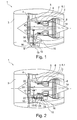
- the auxiliary device transmission device 9 of Fig. 1 is arranged substantially in the radial direction outside of the bypass duct 2 and comprises a drive shaft 13, via which the auxiliary equipment transmission device 9 is connected to a central engine shaft 14.
- the drive shaft 13 drives via gear pairings 19 auxiliary equipment gear shafts on which in turn various auxiliary units 16, such as a fuel pump, a hydraulic pump, a breather or a pneumatic starter are arranged.
- the drive shaft 13 is formed in the manner of a side gear.
- a bevel gear 20 is presently provided, via which the drive shaft 13 is connected to a high-pressure shaft of the engine shaft 14 is, which rotates in the operating state of the jet engine 1 at a higher speed than a coaxial thereto arranged low pressure shaft to which the fan 4 is connected.
- the drive shaft 13 is integrally formed and extends through a so-called inner Strut 17, d. H. a trained with a hollow profile strut, in a substantially radial direction from the engine shaft 14 to the outside through the engine core 5 to a arranged in the region between the engine core 5 and the bypass channel 2 intermediate housing 15 and from there substantially in the radial direction by a through the bypass duct 2 leading outer Strut 18 further outward to the auxiliary gearbox shafts.
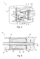
- the auxiliary equipment transmission device 10 with the auxiliary equipment transmission shafts is arranged substantially between the bypass duct 2 and the engine core 5 in the region of the intermediate housing 15.
- An essentially axially extending drive shaft 21 of the auxiliary device transmission device 10 is connected via a bevel gear 22 with an auxiliary shaft 24 in operative connection.
- the auxiliary shaft 24 extends through the inner Strut 17 substantially in the radial direction and is coupled at its end remote from the drive shaft 20 with the engine shaft 14, so that the auxiliary shaft 24 establishes an operative connection between the engine shaft 14 and the drive shaft 20.
- Each auxiliary device transmission device 9, 10, 11 has a generator 12 or 36, which can be arranged in principle on each shaft of the auxiliary device transmission device 9, 10, 11.
- the in the Fig. 1 to 3 Examples shown are described only by way of example for a variety of other possible arrangements of the generators 12 and 36, respectively.
- the generator 12, 36 arranged in the radial direction between the bypass duct 2 and the engine core 5 in the region of the intermediate housing 15, wherein the generator 12, 36 alternatively, for example, also in the radial direction outside of the bypass channel. 2 or in the region of the struts 17, 18 can be arranged.
- the generator 36 is arranged in the region of the intermediate housing 15 on the drive shaft 13 of the auxiliary device transmission device 9 extending in the radial direction to the engine shaft 14.
- the generator 12 is disposed in each case on the substantially axially extending drive shaft 21, wherein the generator 12 in which in the Fig. 2 shown embodiment in Power flow seen from the engine shaft 14 from the auxiliary gearbox shafts and in the in the Fig. 3 shown embodiment is arranged according to the auxiliary equipment gear shafts.
- the arrangement of the generator 12 in the power flow before the auxiliary gearbox shafts has the advantage that the fact that the generator 12 may be a large power consumers, the subsequent auxiliary equipment transmission shafts through which no large benefits must be performed, can be made small.
- the generator 12 is arranged on the drive shaft 21 of the auxiliary device transmission device 10, seen in more detail.
- the generator 12 has a rotor 23 and a stator 25, wherein the stator 25 is fixedly connected to a housing 26 of the generator 12.
- the generator 12 is arranged in the axial direction of the drive shaft 21 in a recess of a housing 27 of the drive shaft 21 between the housing 27 of the drive shaft 21 and a housing 28 of the auxiliary equipment device 10, wherein the housing 26 of the generator 12 both in an abutment region to the housing 27th the drive shaft 21 and in a contact region to the housing 28 of the auxiliary device transmission device 10 each have a sealing surface 29 and 30 respectively.
- an oil separator 30 or 31 is provided on both sides of the generator 12 in the area of the drive shaft 21.
- the drive shaft 21 is present formed as a hollow shaft, wherein in a end portion 34 of the drive shaft 21, a cooling device 33 is arranged with an oil nozzle, by means of which heat can be dissipated by the generator 12 via a circulation of oil in the hollow shaft 21.
- stator 25 and the housing 26 of the generator 12 are divided in the circumferential direction, and in this case formed in two parts or two shells.
- the Indian Fig. 5 closer apparent generator 36 is also formed with a rotor 37, a stator 38 and a housing 39, wherein the rotor 37 via a in the Fig. 7 Closer apparent fixing device 40, which is presently designed as a tongue and groove connection, is rotatably fixed on the drive shaft 13 of the auxiliary equipment gear device 9, so that the rotor 37 is rotated during a rotational movement of the drive shaft 13 of this.
- a partition member 43 which constitutes the stator 38 together with the housing 39 of the generator 36 opposite to the rotor 37 capsules.
- the separating element 43 is formed of a non-magnetic material, so that the operability of the generator 36 is not affected by the partition member 43.
- the separating element 43 is connected via unspecified and for example designed as screws, bolts or the like fasteners with a housing 39 of the generator 36 adjacent housing 44 of the drive shaft 13.
- partition member 43 is not a structural member, a radially extending thickness of the partition member 43 depending on the selected material of the partition member 43 can be kept very small, so that a gap between the rotor 37 and the stator 38 is very small and by the separator 43 caused only small losses.
- the generator 36 has an unspecified cooling device, which supplies the here a wet area performing rotor portion 41 with a coolant, in particular oil.
- the coolant dissipates heat energy arising in the region of the stator 38 during operation of the jet engine 1. Since the coolant comes very close to the stator area 42 representing a drying space, the energy absorption by the coolant is very effective.
- a corrosion of the rotor 37 is advantageously slowed down or prevented by the appropriately designed coolant.
- the housing 39 of the generator 36 and the stator 38 is formed in the circumferential direction in two parts or bivalves, wherein the two parts 45, 46 on the one hand have a hinged connection formed with a hinge 47 and on the other hand a closure device 48.
- both components 45, 46 of the generator 36 each have a flange, via which the components 45, 46 of the generator 36 can be fixed or released from each other, for example via fastening elements designed as screws, and the detachable components 45, 46 of the Generator 36 can be determined according to the drive shaft 13 and released from this.
- the separating element 43 and, if appropriate, the rotor 37 which are not very susceptible to errors, for example in contrast to the stator 38 of the generator 36, can not be detached from the drive shaft 13 in the present case.
- these can also be divided in the circumferential direction, part of the two components 45, 46 of the generator 36 and thus be detachable from the drive shaft 13.
- fastening means 49 may be provided, which especially as a quick release in the form of a so-called V-band clamp is formed.
- a fastening device 49 may be provided in both axial edge regions of the generator 36 for attachment to the housing 44 of the drive shaft 13, wherein the housing 39 of the generator 36 is secured via the fastening device 49 in the axial direction.
- a pin, a bolt or the like may be provided, which in the region of adjacent flanges of the housing 39, 44 in Region of the V-band clamp 49 may be arranged in the axial direction in the flanges.
- the fastening device may be provided for fixing the housing of the generator to a in each case of application to the housing of the generator adjacent component.
Abstract
Description
Die Erfindung betrifft eine Hilfsgerätegetriebeeinrichtung für ein Triebwerk gemäß der im Oberbegriff des Patentanspruches 1 näher definierten Art.The invention relates to an auxiliary device transmission device for an engine according to the closer defined in the preamble of
Hilfsgerätegetriebeeinrichtungen für Triebwerke mit mehreren Hilfsgerätegetriebewellen, die jeweils mit einem Hilfsaggregat, wie beispielsweise einer Brennstoffpumpe, einem Generator oder dergleichen, verbindbar sind, sind aus der Praxis hinlänglich bekannt. Die Hilfsgerätegetriebewellen sind im Wesentlichen achsparallel zueinander angeordnet und an den zur Verfügung stehenden Bauraum im Triebwerk angepasst. Dabei sind sie im Wesentlichen in Umfangsrichtung des Triebwerkes verteilt nebeneinander positioniert und werden über Stirnradstufen von einer mit der Triebwerkswelle wirkverbundenen Antriebswelle der Hilfsgerätegetriebeeinrichtung angetrieben.Auxiliary gearbox devices for multi-accessory gearbox drive engines, each connectable to an auxiliary power unit, such as a fuel pump, a generator, or the like, are well known in the art. The auxiliary gearbox shafts are arranged substantially axially parallel to each other and adapted to the available space in the engine. In this case, they are positioned substantially next to one another distributed in the circumferential direction of the engine and are driven via spur gear stages by a drive shaft of the auxiliary equipment transmission device operatively connected to the engine shaft.
Als unabhängige Stromquelle für eine Stromversorgung einer Triebwerksregelung werden über die Hilfsgerätegetriebeeinrichtungen derartige Generatoren, beispielsweise so genannte Permanent Magnet Alternators (PMAs), angetrieben. Die Generatoren sind mit einer parallel zur Antriebswelle verlaufenden Hilfsgerätegetriebewelle verbindbar und auf dieser anordenbar sowie über diese im Betrieb des Triebwerks mit einer Drehzahl im Hochgeschwindigkeitsbereich von etwa 10.000 bis 24.000 Umdrehungen pro Minute antreibbar. Weiterhin sind über die Hilfsgerätegetriebeeinrichtungen neben PMAs auch im Vergleich zu PMAs größer dimensionierte Generatoren antreibbar, die zur Stromversorgung des gesamten Flugzeugs ausgebildet sind.As an independent power source for a power supply of an engine control such generators, for example so-called permanent magnet alternators (PMAs), driven by the auxiliary equipment transmission devices. The generators are connectable to a parallel to the drive shaft extending auxiliary gear shaft and can be arranged on this and drivable on this in the operation of the engine at a speed in the high-speed range of about 10,000 to 24,000 revolutions per minute. Furthermore, in addition to PMAs, larger-sized generators can be driven via the auxiliary device transmission devices in addition to PMAs, which are designed to supply power to the entire aircraft.
Die Generatoren sind jeweils auf einer separaten Hilfsgerätegetriebewelle der Hilfsgerätegetriebeeinrichtung angeordnet und beispielsweise über Bolzenverbindungen mit einem Gehäuse der Hilfsgerätegetriebeeinrichtungen verbindbar.The generators are each arranged on a separate auxiliary gear shaft of the auxiliary equipment transmission device and connectable, for example via bolt connections with a housing of the auxiliary equipment transmission devices.
Die bekannten Hilfsgerätegetriebeeinrichtungen benötigen nachteilhafterweise einen großen Bauraum und sind durch ein hohes Gesamtgewicht gekennzeichnet.The known auxiliary equipment transmission devices disadvantageously require a large space and are characterized by a high total weight.
Der vorliegenden Erfindung liegt daher die Aufgabe zugrunde, eine bauraumgünstige und ein geringes Gesamtgewicht aufweisende Hilfsgerätegetriebeeinrichtung für ein Triebwerk zur Verfügung zu stellen.The present invention is therefore an object of the invention to provide a space-saving and a low total weight having auxiliary gear device for an engine available.
Erfindungsgemäß wird diese Aufgabe mit einer Hilfsgerätegetriebeeinrichtung mit den Merkmalen des Patentanspruches 1 gelöst.According to the invention, this object is achieved with an auxiliary device transmission device having the features of
Bei einer erfindungsgemäß ausgebildeten Hilfsgerätegetriebeeinrichtung für ein Triebwerk mit wenigstens einer mit einem Hilfsaggregat verbindbaren und von einer Antriebswelle antreibbaren Hilfsgerätegetriebewelle ist die Antriebswelle mit einer Triebwerkswelle des Triebwerks in Wirkverbindung bringbar. Erfindungsgemäß ist vorgesehen, dass wenigstens ein Hilfsaggregat auf der Antriebswelle und/oder im Bereich der Wirkverbindung zwischen der Antriebswelle und der Triebwerkswelle und/oder auf einer mit einem weiteren Hilfsaggregat verbindbaren Hilfsgerätegetriebewelle anordenbar ist.In an inventive auxiliary equipment transmission device for an engine with at least one can be connected to an auxiliary unit and driven by a drive shaft auxiliary equipment gear shaft, the drive shaft with an engine shaft of the engine in operative connection can be brought. According to the invention, it is provided that at least one auxiliary unit can be arranged on the drive shaft and / or in the region of the operative connection between the drive shaft and the engine shaft and / or on an auxiliary equipment transmission shaft which can be connected to a further auxiliary unit.
Die erfindungsgemäße Hilfsgerätegetriebeeinrichtung hat den Vorteil, dass zur Anordnung des wenigstens einen Hilfsaggregats keine separate Hilfsgerätegetriebewelle vorgesehen werden muss, sondern das wenigstens eine Hilfsaggregat auf einer bereits vorhandenen Welle der Hilfsgerätegetriebeeinrichtung anordenbar ist. Hierdurch wird Bauraum und Gewicht eingespart, da die bei bekannten Hilfsgerätegetriebeeinrichtungen für das wenigstens eine Hilfsaggregat vorgesehene Hilfsgerätegetriebewelle entfallen kann. Die erfindungsgemäße Lösung ist somit kostengünstig umsetzbar. Durch den Wegfall der separaten Hilfsgerätegetriebewelle für das wenigstens eine Hilfsaggregat wird auch eine Länge der Hilfsgerätegetriebeeinrichtung in Umfangsrichtung des Triebwerks reduziert, wodurch wiederum eine Komplexität von Öl- und Luftleitungen zur Versorgung der Hilfsaggregate der nunmehr verkürzten Hilfsgerätegetriebeeinrichtung reduziert ist.The auxiliary device transmission device according to the invention has the advantage that for the arrangement of at least one auxiliary unit no separate auxiliary gear shaft must be provided, but at least one auxiliary unit can be arranged on an existing shaft of the auxiliary gear device. As a result, space and weight is saved, since the provided in known auxiliary equipment transmission devices for the at least one auxiliary unit auxiliary gearbox shaft can be omitted. The solution according to the invention is thus feasible inexpensively. By eliminating the separate auxiliary gear shaft for the at least one auxiliary unit and a length of the auxiliary equipment gear device is reduced in the circumferential direction of the engine, which in turn complexity of oil and air lines for supplying the auxiliary units of the now shortened auxiliary equipment gear device is reduced.
Bei der erfindungsgemäßen Hilfsgerätegetriebeeinrichtung kann ein Hilfsaggregat auf einer der beschriebenen Wellen angeordnet sein. Es können auch mehrere Hilfsaggregate vorgesehen sein, welche entweder gemeinsam auf einer der beschriebenen Wellen oder auf verschiedenen der beschriebenen Wellen angeordnet sind.In the auxiliary device transmission device according to the invention, an auxiliary unit may be arranged on one of the shafts described. It can also be provided a plurality of auxiliary units, which are arranged either together on one of the waves described or on various of the waves described.
Bei einer vorteilhaften Weiterbildung der erfindungsgemäßen Hilfsgerätegetriebeeinrichtung ist das wenigstens eine Hilfsaggregat vorzugsweise als Generator ausgeführt und zumindest teilweise lösbar auf der Antriebswelle, im Bereich der Wirkverbindung zwischen der Antriebswelle und der Triebwerkswelle oder der Hilfsgerätegetriebewelle anordenbar, so dass die Teile des Hilfsaggregats im Schadensfall innerhalb kurzer Zeit ersetzt oder gewartet werden können.In an advantageous development of the auxiliary device transmission device according to the invention, the at least one auxiliary unit is preferably designed as a generator and at least partially detachable on the drive shaft, in the region of the operative connection between the drive shaft and the engine shaft or the auxiliary equipment gear shaft can be arranged, so that the parts of the auxiliary unit in case of damage within a short time can be replaced or serviced.
Um eine Austauschbarkeit zumindest der wartungsintensiveren Bauteile des Hilfsaggregats auf einfache und schnelle Weise zu ermöglichen, können wenigstens ein Stator und ein Gehäuse des vorzugsweise als Generator ausgeführten Hilfsaggregates lösbar auf der Antriebswelle, im Bereich der Wirkverbindung zwischen der Antriebswelle und der Triebwerkswelle oder Hilfsgerätegetriebewelle angeordnet und ein Rotor fest mit einer Welle verbunden sein. Der Rotor, welcher im Gegensatz zu dem Stator des Generators nicht sehr fehleranfällig ist, kann bei einem Austausch des Stators und des Gehäuses des Generators mit der Welle verbunden bleiben.In order to enable interchangeability of at least the more maintenance-intensive components of the auxiliary unit in a simple and rapid manner, at least one stator and a housing of the auxiliary unit preferably designed as a generator detachably arranged on the drive shaft, in the region of the operative connection between the drive shaft and the engine shaft or auxiliary equipment gear shaft and a Rotor be firmly connected to a shaft. The rotor, which in contrast to the stator of the generator is not very prone to failure, can remain connected to the shaft when replacing the stator and the housing of the generator.
Bei einer vorteilhaften Ausführung der Hilfsgerätegetriebeeinrichtung ist der Rotor über eine insbesondere als Nut-Federverbindung ausgebildete Festlegungseinrichtung mit der Welle drehfest verbindbar.In an advantageous embodiment of the auxiliary device transmission device, the rotor can be connected in a rotationally fixed manner to the shaft via a fixing device designed in particular as a tongue and groove connection.
Von einer Welle lösbare Bauteile des Generators sind bei einer konstruktiv einfachen Ausführung der Erfindung in Umfangsrichtung wenigstens zweiteilig bzw. zweischalig ausgebildet. Zusätzlich ist es auch möglich, dass der Rotor ebenfalls in vergleichbarer Weise wie der Stator und das Gehäuse zweigeteilt ausgebildet ist und mitsamt dem Stator und dem Gehäuse von der Welle lösbar ist.From a shaft detachable components of the generator are formed in a structurally simple embodiment of the invention in the circumferential direction at least two parts or two shells. In addition, it is also possible that the rotor is also formed in two parts in a comparable manner as the stator and the housing and is releasable together with the stator and the housing of the shaft.
Die lösbaren Bauteile des Generators sind bei einer konstruktiv einfachen Ausführung der Erfindung einerseits mit einer Gelenkverbindung miteinander schwenkbar gekoppelt und andererseits über eine Verschlusseinrichtung zur Festlegung auf einer Welle der Hilfsgerätegetriebeeinrichtung miteinander verbindbar und manschettenartig an der Welle festlegbar. Ein Austausch der Teile des Generators mittels einer derartigen Scharnier-Verschluss-Verbindung ist besonders einfach möglich.The releasable components of the generator are pivotally coupled to each other in a structurally simple embodiment of the invention on the one hand with a hinge connection and on the other hand via a closure device for fixing on a shaft of the auxiliary equipment gear device connected to each other and cuffs fixed to the shaft. One Replacement of the parts of the generator by means of such a hinge-closure connection is particularly easy.
Alternativ oder zusätzlich hierzu können insbesondere die lösbaren Bauteile des Generators mittels wenigstens einer das Gehäuse des Generators umfangsseitig umfassenden Befestigungseinrichtung auf der Welle angeordnet werden. Die Befestigungseinrichtung kann insbesondere einen Schnellverschluss darstellen und beispielsweise als so genannte V-Band-Schelle ausgebildet sein. Die austauschbaren Teile des Generators können hierdurch völlig getrennt voneinander sein.Alternatively or additionally, in particular, the detachable components of the generator can be arranged on the shaft by means of at least one fastening device which encloses the housing of the generator on the circumference. The fastening device can in particular represent a quick release and be designed, for example, as a so-called V-band clamp. The replaceable parts of the generator can thereby be completely separate from each other.
Um den Generator sicher auf der Welle festzulegen, kann die Befestigungseinrichtung zum Zusammenwirken mit einem in axialer Richtung seitlichen Bereich des Gehäuses des Generators und einem an diesen Bereich des Gehäuses angrenzenden Bereich eines benachbarten Gehäuses ausgeführt sein, so dass der Generator insbesondere auch in axialer Richtung gegenüber dem im Einbauzustand benachbarten Gehäuse gesichert ist.In order to fix the generator securely on the shaft, the fastening device can be designed to cooperate with an axially lateral region of the housing of the generator and an adjacent to this region of the housing portion of an adjacent housing, so that the generator in particular in the axial direction opposite is secured in the installed state adjacent housing.
Der Generator kann zur Anordnung im Bereich eines Endabschnitts der Welle ausgebildet sein, wobei der Endabschnitt der Welle von dem Gehäuse des Generators vollständig eingeschlossen ist. In einer hierzu alternativen Ausführung der Erfindung ist der Generator zur Anordnung auf einer im Bereich des Generators durchgängigen Welle der Hilfsgerätegetriebeeinrichtung des Triebwerks ausgebildet, wobei ein Gehäuse des Generators insbesondere mit Gehäusen von benachbarten Bauteilen zusammenwirkt.The generator may be configured to be located in the region of an end portion of the shaft, the end portion of the shaft being completely enclosed by the housing of the generator. In an alternative embodiment of the invention, the generator is designed for arrangement on a continuous in the region of the generator shaft of the auxiliary equipment transmission device of the engine, wherein a housing of the generator interacts in particular with housings of adjacent components.
Um im Betrieb des Generators insbesondere im Bereich des Stators entstehende Wärmeenergie von dem Generator abzuführen, ist die Welle, auf der der Generator anordenbar ist, bei einer vorteilhaften Ausführung der erfindungsgemäßen Hilfsgerätegetriebeeinrichtung als Hohlwelle ausgebildet und eine Kühleinrichtung mit einem Kühlmittel vorgesehen, welches zur Kühlung des Generators durch die Welle führbar ist.In order to dissipate heat energy arising during operation of the generator, in particular in the region of the stator, from the generator, is the shaft on which the generator can be arranged, formed in an advantageous embodiment of the auxiliary device gear device according to the invention as a hollow shaft and a cooling device provided with a coolant, which is feasible for cooling the generator by the shaft.
Eine Abführung von sehr großen, im Bereich des Generators entstehenden Wärmemengen, beispielsweise bei großen Generatoren, welche zur Stromversorgung eines gesamten Flugzeugs vorgesehen sind, kann bei einer vorteilhaften Ausführung der Erfindung mit einem ein separates Kühlsystem aufweisenden Generator geschaffen werden, welches insbesondere im Bereich des Stators verlaufende Kühlleitungen aufweist.A discharge of very large amounts of heat generated in the region of the generator, for example, in large generators, which are provided to power an entire aircraft can be provided in an advantageous embodiment of the invention with a separate cooling system having a generator, which in particular in the region of the stator having running cooling lines.
Bei einer besonders vorteilhaften Ausführung der erfindungsgemäßen Hilfsgerätegetriebeeinrichtung ist ein wenigstens einen Stator aufweisender Statorbereich des Generators gegenüber einem wenigstens einen Rotor aufweisenden Rotorbereich des Generators getrennt. Hierdurch kann auf konstruktiv einfache Art und Weise eine weiter verbesserte und besonders effektive Kühlung des Generators sichergestellt werden, da das Kühlmedium nahe an den Stator gelangen kann, in dessen Bereich ein Großteil der Wärme in einem Betriebszustand des Generators entsteht.In a particularly advantageous embodiment of the auxiliary device transmission device according to the invention, a stator region of the generator having at least one stator is separated from a rotor region of the generator having at least one rotor. As a result, a further improved and particularly effective cooling of the generator can be ensured in a structurally simple manner, since the cooling medium can reach close to the stator, in the region of which a large part of the heat is produced in an operating state of the generator.
Eine vollständige Abdichtung des einen Trockenraum darstellenden Statorbereichs gegenüber dem einen Nassbereich darstellenden Rotorbereich ist mit einfachen Mitteln möglich, wohingegen bei Generatoren mit einer Kühlung im Bereich einer Hohlwelle durch die zur Abtrennung des Trockenraums vorgesehenen Ölabscheider geringe Mengen an Öl in einen Bereich des Stators eintreten können. Durch die erfindungsgemäße Separierung des Rotorbereichs von dem Statorbereich bzw. die Kapselung des Statorbereichs wird vorteilhafterweise sichergestellt, dass das Kühlmedium nicht in Kontakt mit elektrischen Komponenten des Statorbereichs tritt. Da der Rotor im Betriebszustand des Generators von dem Kühlmedium umspült wird, kann er bei der Wahl eines entsprechenden Kühlmediums durch das Kühlmedium zusätzlich vor Korrosion geschützt werden. Die Kühlung des Generators kann dabei über eine dem Generator zugeordnete Kühleinrichtung durchgeführt werden. Die Kühleinrichtung kann auch an ein weiteres Kühlsystem der Hilfsgerätegetriebeeinrichtung oder des gesamten Triebwerks angeschlossen sein, so dass die Kühleinrichtung des Generators beispielsweise keinen separaten Tank und/oder keine separate Pumpe aufweisen muss.A complete sealing of the stator area representing a dry space with respect to the rotor area representing a wet area is possible by simple means, whereas small amounts of oil can enter into a region of the stator in the case of generators with cooling in the area of a hollow shaft through the oil separators provided for separating the drying space. By the separation according to the invention the rotor region of the stator or the encapsulation of the stator is advantageously ensured that the cooling medium does not come into contact with electrical components of the stator. Since the rotor is lapped by the cooling medium in the operating state of the generator, it can be additionally protected against corrosion when choosing a suitable cooling medium by the cooling medium. The cooling of the generator can be carried out via a generator associated with the cooling device. The cooling device can also be connected to a further cooling system of the auxiliary device transmission device or of the entire engine, so that the cooling device of the generator does not have to have a separate tank and / or a separate pump, for example.
Bei einer konstruktiv einfachen Weiterbildung der Erfindung ist zur Trennung des Statorbereichs von dem Rotorbereich ein zwischen Stator und Rotor verlaufendes Trennelement vorgesehen. Da das Trennelement kein Strukturbauteil darstellt und dementsprechend keine tragende Funktion zu erfüllen hat, kann es sehr dünn ausgebildet werden. Ein Abstand zwischen dem Stator und dem Rotor, welcher für die Effektivität des Generators eine entscheidende Rolle spielt, kann somit sehr klein gehalten werden. Eventuelle Verluste durch den durch das Trennelement geringfügig vergrößerten Abstand zwischen dem Rotor und dem Stator des Generators können gegebenenfalls durch eine geringe Erhöhung einer Magnetfeldstärke im Vergleich zu einem herkömmlichen Generator ohne Trennelement auf einfache Weise ausgeglichen werden.In a structurally simple development of the invention, a separating element extending between the stator and the rotor is provided for separating the stator region from the rotor region. Since the separating element is not a structural component and accordingly has no supporting function to fulfill, it can be made very thin. A distance between the stator and the rotor, which plays a crucial role for the efficiency of the generator, can thus be kept very small. Any losses due to the distance between the rotor and the stator of the generator, which is slightly increased by the separating element, can be compensated in a simple manner by a small increase in a magnetic field strength in comparison with a conventional generator without a separating element.
Um einen Einfluss des Trennelements auf einen Wirkungsgrad des Generators so gering wie möglich zu halten, besteht das Trennelement bei einer vorteilhaften Ausführung der Erfindung aus einem nicht-magnetischen Material.To keep an influence of the separator on an efficiency of the generator as low as possible, there is the separating element in an advantageous embodiment of the invention of a non-magnetic material.
Das Trennelement ist bei einer konstruktiv einfachen Ausführung der Erfindung als separates Bauteil ausgebildet, welches über Befestigungselemente mit einem Gehäuse, insbesondere einem Statorgehäuse des Generators verbindbar ist. Ein Material des Trennelements kann bei dieser Ausführung vorteilhafterweise unabhängig von einem Material des Gehäuses gewählt werden. Das Trennelement kann beispielsweise über Bolzen, Schrauben oder ähnliches an dem Gehäuse festgelegt werden. Bei einer hierzu alternativen Ausführung der Erfindung ist das Trennelement integral mit einem Gehäuse des Generators gebildet.The separating element is formed in a structurally simple embodiment of the invention as a separate component, which is connectable via fastening elements with a housing, in particular a stator housing of the generator. A material of the separating element can advantageously be chosen independently of a material of the housing in this embodiment. The separating element can be fixed to the housing, for example by means of bolts, screws or the like. In an alternative embodiment of the invention, the separating element is formed integrally with a housing of the generator.
Der Generator kann beispielsweise zur Stromversorgung einer Triebwerksregelung oder zur Stromversorgung eines gesamten Flugzeugs mit einer dem jeweiligen Anwendungsfall entsprechenden Dimensionierung ausgebildet sein.The generator can be designed, for example, to supply power to an engine control system or to supply power to an entire aircraft with a dimensioning corresponding to the respective application.
Neben der Ausbildung als Generator kann das wenigstens eine Hilfsaggregat beispielsweise als Brennstoffpumpe, Hydraulikpumpe, Entlüfter, pneumatischer Starter oder dergleichen ausgebildet sein.In addition to being designed as a generator, the at least one auxiliary unit can be designed, for example, as a fuel pump, hydraulic pump, deaerator, pneumatic starter or the like.
Sowohl die in den Patentansprüchen angegebenen Merkmale als auch die in den nachfolgenden Ausführungsbeispielen der erfindungsgemäßen Hilfsgerätegetriebeeinrichtung angegebenen Merkmale sind jeweils für sich alleine oder in beliebiger Kombination miteinander geeignet, den erfindungsgemäßen Gegenstand weiterzubilden. Die jeweiligen Merkmalskombinationen stellen hinsichtlich der Weiterbildung des Gegenstandes nach der Erfindung keine Einschränkung dar, sondern weisen im Wesentlichen lediglich beispielhaften Charakter auf.Both the features specified in the claims and the features specified in the following embodiments of the auxiliary device gear device according to the invention are each suitable alone or in any combination with each other to develop the subject invention. The respective combinations of features with respect to the development of the subject by The invention is not limited, but have essentially only exemplary character.
Weitere Vorteile und vorteilhafte Ausführungsformen der erfindungsgemäßen Hilfsgerätegetriebeeinrichtung ergeben sich aus den Patentansprüchen und den nachfolgend unter Bezugnahme auf die Zeichnung prinzipmäßig beschriebenen Ausführungsbeispielen.Further advantages and advantageous embodiments of the auxiliary device transmission device according to the invention will become apparent from the claims and the embodiments described in principle below with reference to the drawings.
Es zeigt:
- Fig. 1
- eine stark schematisierte Längsschnittansicht eines Strahltriebwerkes mit einer im Wesentlichen in radialer Richtung außerhalb eines Nebenstromkanals des Strahltriebwerks angeordneten Hilfsgerätegetriebeeinrichtung, welche einen im Bereich eines Zwischengehäuses des Strahltriebwerks angeordneten Generator aufweist;
- Fig. 2
- eine stark schematisierte Längsschnittansicht des Strahltriebwerks der
Fig. 1 mit einer im Wesentlichen im Bereich des Zwischengehäuses des Strahltriebwerks angeordneten Hilfsgerätegetriebeeinrichtung, wobei ein Generator im Bereich einer Antriebswelle der Hilfsgerätegetriebeeinrichtung angeordnet ist; - Fig. 3
- eine der
Fig. 2 entsprechende Darstellung eines Strahltriebwerks mit einer im Wesentlichen im Bereich des Zwischengehäuses des Strahltriebwerks angeordneten Hilfsgerätegetriebeeinrichtung, wobei ein Generator an einer alternativen Position der Antriebswelle der Hilfsgerätegetriebeeinrichtung angeordnet ist; - Fig. 4
- eine vereinfachte Darstellung des Generators der
Fig. 2 , welcher auf der Antriebswelle der Hilfsgerätegetriebeeinrichtung angeordnet ist; - Fig. 5
- eine vereinfachte Darstellung einer Weiterbildung des Generators der
Fig. 4 mit einem einen Statorbereich von einem Rotorbereich trennenden Trennelement; - Fig. 6
- eine vereinfachte Schnittdarstellung eines Ausschnitts des Generators der
Fig. 5 mit einem einem Gehäuse des Generators benachbarten Gehäuse, wobei eine Befestigungseinrichtung zur Festlegung des Gehäuses des Generators an dem benachbarten Gehäuse ersichtlich ist; und - Fig. 7
- eine Querschnittansicht durch einen in axialer Richtung mittleren Bereich des Generators der
Fig. 5 , wobei eine Teilung des Generators in Umfangsrichtung gezeigt ist.
- Fig. 1
- a highly schematic longitudinal sectional view of a jet engine with an arranged substantially in the radial direction outside of a bypass duct of the jet engine auxiliary equipment transmission device having a arranged in the region of an intermediate housing of the jet engine generator;
- Fig. 2
- a highly schematic longitudinal sectional view of the jet engine of
Fig. 1 with an auxiliary device arranged substantially in the region of the intermediate housing of the jet engine, a generator being arranged in the region of a drive shaft of the auxiliary device transmission device; - Fig. 3
- one of the
Fig. 2 corresponding representation of a jet engine with a substantially in the region of the intermediate housing of the jet engine arranged auxiliary equipment transmission device, wherein a generator is disposed at an alternative position of the drive shaft of the auxiliary equipment transmission device; - Fig. 4
- a simplified representation of the generator of
Fig. 2 which is arranged on the drive shaft of the auxiliary equipment transmission device; - Fig. 5
- a simplified representation of a development of the generator of
Fig. 4 a separator separating a stator region from a rotor region; - Fig. 6
- a simplified sectional view of a section of the generator of
Fig. 5 with a housing adjacent to a housing of the generator, wherein a fastening means for fixing the housing of the generator to the adjacent housing can be seen; and - Fig. 7
- a cross-sectional view through an axially middle portion of the generator of the
Fig. 5 wherein a division of the generator is shown in the circumferential direction.
Die
Das Strahltriebwerk 1 weist einen Nebenstromkanal 2 und einen Einlaufbereich 3 auf, wobei sich an den Einlaufbereich 3 stromab ein Bläser 4 in an sich bekannter Art und Weise anschließt. Wiederum stromab des Bläsers 4 teilt sich der Fluidstrom im Strahltriebwerk 1 in einen Nebenstrom und einen Kernstrom auf, wobei der Nebenstrom durch den Nebenstromkanal 2 und der Kernstrom in einen Triebwerkskern 5 strömt, der wiederum in an sich bekannter Art und Weise mit einer Verdichtereinrichtung 6, einem Brenner 7, einer zum Antrieb des Bläsers 4 vorgesehenen Niederdruckturbine 8 und einer zum Antrieb der Verdichtereinrichtung 6 vorgesehenen Hochdruckturbine 8.1 ausgeführt ist.The
In den
Die Hilfsgerätegetriebeeinrichtung 9 der
Zur Anbindung der Antriebswelle 13 der Hilfsgerätegetriebeeinrichtung 9 an die Triebwerkswelle 14 ist vorliegend eine Kegelradverzahnung 20 vorgesehen, über welche die Antriebswelle 13 an eine Hochdruckwelle der Triebwerkswelle 14 angebunden ist, welche im Betriebszustand des Strahltriebwerks 1 mit höherer Drehzahl rotiert als eine koaxial dazu angeordnete Niederdruckwelle, an welche der Bläser 4 angebunden ist.To connect the
Die Antriebswelle 13 ist einstückig ausgebildet und verläuft durch einen so genannten inneren Strut 17, d. h. eine mit einem Hohlprofil ausgebildete Strebe, in im Wesentlichen radialer Richtung von der Triebwerkswelle 14 nach außen hin durch den Triebwerkskern 5 zu einem im Bereich eines zwischen dem Triebwerkskern 5 und dem Nebenstromkanal 2 angeordneten Zwischengehäuses 15 und von dort im Wesentlichen in radialer Richtung durch einen durch den Nebenstromkanal 2 führenden äußeren Strut 18 weiter nach außen hin zu den Hilfsgerätegetriebewellen.The
Bei dem in der
Eine im Wesentlichen in axialer Richtung verlaufende Antriebwelle 21 der Hilfsgerätegetriebeeinrichtung 10 steht über eine Kegelradverzahnung 22 mit einer Hilfswelle 24 in Wirkverbindung. Die Hilfswelle 24 verläuft durch den inneren Strut 17 im Wesentlichen in radialer Richtung und ist an ihrem der Antriebswelle 20 abgewandten Ende mit der Triebwerkswelle 14 gekoppelt, so dass die Hilfswelle 24 eine Wirkverbindung zwischen der Triebwerkswelle 14 und der Antriebswelle 20 herstellt.An essentially axially extending
Das in der
Jede Hilfsgerätegetriebeeinrichtung 9, 10, 11 weist einen Generator 12 bzw. 36 auf, welcher im Prinzip auf jeder Welle der Hilfsgerätegetriebeeinrichtung 9, 10, 11 anordenbar ist. Die in den
Bei sämtlichen in den
In dem in der
Sowohl bei dem in der
In der
Um den vorliegend in einem Trockenraum angeordneten Stator 24 und den ebenfalls in einem Trockenraum angeordneten Rotor 23 gegenüber den benachbarten Gehäusen 27 bzw. 28 abzudichten, ist beidseits des Generators 12 im Bereich der Antriebswelle 21 jeweils ein Ölabscheider 30 bzw. 31 vorgesehen.In order to seal the
Zur Kühlung des sich in einem Betrieb des Strahltriebwerks 1 erhitzenden Stators 25 ist die Antriebswelle 21 vorliegend als Hohlwelle ausgebildet, wobei in einem Endbereich 34 der Antriebswelle 21 eine Kühleinrichtung 33 mit einer Öldüse angeordnet ist, mittels welcher Wärme von dem Generator 12 über eine Zirkulation von Öl in der Hohlwelle 21 abgeführt werden kann.In order to cool the
Um den Generator 12 einfach auf der Antriebswelle 21 festlegen und von dieser lösen zu können, sind der Stator 25 und das Gehäuse 26 des Generators 12 in Umfangsrichtung geteilt, und vorliegend zweiteilig bzw. zweischalig ausgebildet.In order to simply fix the
Die genaue Ausführung der Teilung des Generators 12 ist in der
Der in der
Im Unterschied zu dem Generator 12 ist bei dem Generator 36 zwischen einem den Rotor 37 aufnehmenden Rotorbereich 41 und einem den Stator 38 aufnehmenden Statorbereich 42 ein eine Gehäuseeinrichtung darstellendes Trennelement 43 angeordnet, welches den Stator 38 zusammen mit dem Gehäuse 39 des Generators 36 gegenüber dem Rotor 37 kapselt. Das Trennelement 43 ist aus einem nicht-magnetischen Material ausgebildet, so dass die Funktionsfähigkeit des Generators 36 durch das Trennelement 43 nicht beeinträchtigt wird.In contrast to the
In der gezeigten Ausführung ist das Trennelement 43 über nicht näher ersichtliche und beispielsweise als Schrauben, Bolzen oder dergleichen ausgebildete Befestigungselemente mit einem dem Gehäuse 39 des Generators 36 benachbarten Gehäuse 44 der Antriebswelle 13 verbunden.In the embodiment shown, the separating
Da das Trennelement 43 kein Strukturbauteil darstellt, kann eine sich in radialer Richtung erstreckende Dicke des Trennelements 43 in Abhängigkeit von dem gewählten Material des Trennelements 43 sehr klein gehalten werden, so dass ein Spalt zwischen dem Rotor 37 und dem Stator 38 sehr gering ist und durch das Trennelement 43 nur geringe Verluste verursacht werden.Since the
Der Generator 36 weist eine nicht näher ersichtliche Kühleinrichtung auf, welche den hier einen Nassbereich darstellenden Rotorbereich 41 mit einem Kühlmittel, insbesondere Öl, versorgt. Durch das Kühlmittel wird im Betrieb des Strahltriebwerks 1 im Bereich des Stators 38 entstehende Wärmeenergie von diesem abgeführt. Da das Kühlmittel sehr nah an den einen Trockenraum darstellenden Statorbereich 42 heranreicht, ist die Energieaufnahme durch das Kühlmittel sehr effektiv. Zusätzlich wird durch das entsprechend ausgebildete Kühlmittel eine Korrosion des Rotors 37 vorteilhafterweise verlangsamt bzw. unterbunden.The
Um den Generator 36 auf einfache Weise beispielsweise zu Wartungs- oder Reparaturarbeiten von der Antriebswelle 13 entfernen zu können, ist das Gehäuse 39 des Generators 36 und der Stator 38 in Umfangsrichtung vorliegend zweigeteilt bzw. zweischalig ausgebildet, wobei die beiden Teile 45, 46 einerseits eine mit einem Scharnier 47 ausgebildete Gelenkverbindung und andererseits eine Verschlusseinrichtung 48 aufweisen. Im Bereich der Verschlusseinrichtung 48 weisen beide Bauteile 45, 46 des Generators 36 jeweils einen Flansch auf, über welchen die Bauteile 45, 46 des Generators 36 beispielsweise über als Schrauben ausgebildete Befestigungselemente aneinander festgelegt oder voneinander gelöst werden können und die lösbaren Bauteile 45, 46 des Generators 36 entsprechend auf der Antriebswelle 13 festgelegt bzw. von dieser gelöst werden können.To remove the
Das Trennelement 43 und gegebenenfalls der Rotor 37, welche im Unterschied beispielsweise zu dem Stator 38 des Generators 36 nicht sehr fehleranfällig sind, sind vorliegend nicht von der Antriebswelle 13 lösbar. Bei einer alternativen Ausführung der Erfindung können diese ebenfalls in Umfangsrichtung geteilt, Bestandteil der beiden Bauteile 45, 46 des Generators 36 und somit lösbar von der Antriebswelle 13 sein.The separating
Im Bereich der Verschlusseinrichtung 34 und der Gelenkverbindung können Dichtelemente vorgesehen sein.In the region of the
Um eine feste Anbindung des Generators 36 an die Antriebswelle 13 zu schaffen, kann alternativ oder zusätzlich zu der manschettenartigen Gelenk- und Verschlusseinrichtung 47, 48 in einem in axialer Richtung an das Gehäuse 44 der Antriebswelle 13 grenzenden Bereich des Gehäuses 39 des Generators 36 eine in der
Um eine Verdrehung des Gehäuses 44 der Antriebswelle 13 gegenüber dem Gehäuse 39 des Generators 36 insbesondere im Betrieb des Triebwerks 1 zu verhindern, kann beispielsweise ein Pin, ein Bolzen oder dergleichen vorgesehen sein, welcher im Bereich von aneinander grenzenden Flanschen der Gehäuse 39, 44 im Bereich der V-Band-Schelle 49 in axialer Richtung in den Flanschen angeordnet sein kann.In order to prevent a rotation of the
Bei einer alternativen Anordnung des Generators auf einer Welle kann die Befestigungseinrichtung zur Festlegung des Gehäuses des Generators an einem im jeweiligen Anwendungsfall an das Gehäuse des Generators grenzenden Bauteil vorgesehen sein.In an alternative arrangement of the generator on a shaft, the fastening device may be provided for fixing the housing of the generator to a in each case of application to the housing of the generator adjacent component.
- 11
- StrahltriebwerkJet engine
- 22
- NebenstromkanalBypass duct
- 33
- Einlaufbereichintake area
- 44
- Bläserblowers
- 55
- TriebwerkskernEngine core
- 66
- Verdichtereinrichtungcompressor means
- 77
- Brennerburner
- 88th
- NiederdruckturbineLow-pressure turbine
- 8.18.1
- HochdruckturbineHigh-pressure turbine
- 9, 10, 119, 10, 11
- HilfsgerätegetriebeeinrichtungAccessory gearbox unit
- 1212
- Generatorgenerator
- 1313
- Antriebswelledrive shaft
- 1414
- TriebwerkswelleEngine shaft
- 1515
- Zwischengehäuseintermediate housing
- 1616
- Hilfsaggregatauxiliary power unit
- 1717
- innerer Strutinner strut
- 1818
- äußerer Strutouter strut
- 1919
- Zahnradpaarunggear pair
- 2020
- Kegelradverzahnungbevel gear
- 2121
- Antriebswelledrive shaft
- 2222
- Kegelradverzahnungbevel gear
- 2323
- Rotorrotor
- 2424
- Hilfswelleauxiliary shaft
- 2525
- Statorstator
- 2626
- Gehäuse des GeneratorsHousing of the generator
- 2727
- Gehäuse der AntriebswelleHousing of the drive shaft
- 2828
- Gehäuse der HilfsgerätegetriebeeinrichtungHousing of the auxiliary device transmission device
- 29, 3029, 30
- Dichtflächesealing surface
- 31, 3231, 32
- Ölabscheideroil separator
- 3333
- Kühleinrichtungcooling device
- 3434
- Endbereich der AntriebswelleEnd portion of the drive shaft
- 3535
- Öldüseoil nozzle
- 3636
- Generatorgenerator
- 3737
- Rotorrotor
- 3838
- Statorstator
- 3939
- Gehäuse des GeneratorsHousing of the generator
- 4040
- Festlegungseinrichtungsetter
- 4141
- Rotorbereichrotor area
- 4242
- Statorbereichstator
- 4343
- Trennelementseparating element
- 4444
- Gehäuse der AntriebswelleHousing of the drive shaft
- 45, 4645, 46
- Bauteile des GeneratorsComponents of the generator
- 4747
- Scharnierhinge
- 4848
- Verschlusseinrichtungclosure device
- 4949
- Befestigungseinrichtungfastening device
Claims (15)
Applications Claiming Priority (1)
| Application Number | Priority Date | Filing Date | Title |
|---|---|---|---|
| DE102011112250A DE102011112250A1 (en) | 2011-09-02 | 2011-09-02 | Auxiliary gear device for an engine |
Publications (2)
| Publication Number | Publication Date |
|---|---|
| EP2565420A2 true EP2565420A2 (en) | 2013-03-06 |
| EP2565420A3 EP2565420A3 (en) | 2017-11-22 |
Family
ID=46963417
Family Applications (1)
| Application Number | Title | Priority Date | Filing Date |
|---|---|---|---|
| EP12181534.4A Withdrawn EP2565420A3 (en) | 2011-09-02 | 2012-08-23 | Accessory gearbox device for a turbine engine |
Country Status (3)
| Country | Link |
|---|---|
| US (1) | US9032702B2 (en) |
| EP (1) | EP2565420A3 (en) |
| DE (1) | DE102011112250A1 (en) |
Cited By (2)
| Publication number | Priority date | Publication date | Assignee | Title |
|---|---|---|---|---|
| WO2017114555A1 (en) * | 2015-12-29 | 2017-07-06 | Arcelik Anonim Sirketi | Electric motor with improved heat dissipation and assemblage |
| EP3431714A1 (en) * | 2017-07-17 | 2019-01-23 | Pratt & Whitney Canada Corp. | Air inlet for a gas turbine engine |
Families Citing this family (11)
| Publication number | Priority date | Publication date | Assignee | Title |
|---|---|---|---|---|
| US10308365B2 (en) * | 2015-10-12 | 2019-06-04 | Codrin-Gruie (CG) Cantemir | Fully integrated hybrid electric jet engine |
| US10107130B2 (en) * | 2016-03-24 | 2018-10-23 | United Technologies Corporation | Concentric shafts for remote independent variable vane actuation |
| US11131208B2 (en) | 2016-09-01 | 2021-09-28 | Rolls-Royce North American Technologies, Inc. | Embedded electric generator in turbine engine |
| GB201616759D0 (en) * | 2016-10-03 | 2016-11-16 | Rolls Royce Deutschland Ltd & Co Kg | Accessory gearbox for a gas turbine engine |
| US11333077B2 (en) * | 2019-05-06 | 2022-05-17 | The Boeing Company | Systems and methods for transferring mechanical power in a turbine engine |
| GB201910011D0 (en) * | 2019-07-12 | 2019-08-28 | Rolls Royce Plc | Gas turbine engine electrical generator |
| GB201910009D0 (en) | 2019-07-12 | 2019-08-28 | Rolls Royce Plc | Gas turbine engine electrical generator |
| GB201910008D0 (en) | 2019-07-12 | 2019-08-28 | Rolls Royce Plc | Gas turbine engine electrical generator |
| GB201910010D0 (en) | 2019-07-12 | 2019-08-28 | Rolls Royce Plc | Gas turbine engine electrical generator |
| US11384693B2 (en) | 2020-05-15 | 2022-07-12 | Pratt & Whitney Canada Corp. | Through-flow gas turbine engine with electric motor and electric generator |
| US11365706B2 (en) | 2020-11-04 | 2022-06-21 | William Todd Hodges | Turbine engine system utilizing an augmented combustion module |
Family Cites Families (36)
| Publication number | Priority date | Publication date | Assignee | Title |
|---|---|---|---|---|
| GB190306098A (en) * | 1903-03-16 | 1903-05-21 | Ernest Sherwood Woollard Moore | Improvements in Electric Motor-generators and other Dynamo Electric Machines. |
| US2402547A (en) * | 1942-05-08 | 1946-06-25 | Chrysler Corp | Combined starter and generator drive |
| GB652351A (en) * | 1942-09-07 | 1951-04-25 | Air Equipement | Improvements in and relating to the means for driving auxiliary parts or apparatus on board aircraft |
| US2716709A (en) * | 1953-07-31 | 1955-08-30 | Rowe Walker Eliott | Casings for electric motors, generators, and the like |
| US4335323A (en) * | 1980-01-17 | 1982-06-15 | Ambac Industries, Incorporated | Stamped sheet metal frame for dynamoelectric machine |
| US4525995A (en) * | 1983-04-04 | 1985-07-02 | Williams International Corporation | Oil scavening system for gas turbine engine |
| GB8525096D0 (en) * | 1985-10-11 | 1985-11-13 | Lucas Ind Plc | Speed control unit |
| US5114103A (en) * | 1990-08-27 | 1992-05-19 | General Electric Company | Aircraft engine electrically powered boundary layer bleed system |
| GB9313905D0 (en) * | 1993-07-06 | 1993-08-25 | Rolls Royce Plc | Shaft power transfer in gas turbine engines |
| JP3522943B2 (en) * | 1996-01-18 | 2004-04-26 | 三菱電機株式会社 | Rotating electric machine rotor |
| EP1130221A1 (en) * | 2000-02-14 | 2001-09-05 | Techspace Aero S.A. | Method and device for aeronautic engine lubrication |
| US6515383B1 (en) * | 2000-11-06 | 2003-02-04 | Satcon Technology Corporation | Passive, phase-change, stator winding end-turn cooled electric machine |
| ES2319392T3 (en) * | 2001-04-20 | 2009-05-07 | Converteam Ltd | REFRIGERATION OF A WINDING ENTREHIERRO OF ELECTRICAL MACHINES. |
| US6933633B2 (en) | 2001-10-03 | 2005-08-23 | Nissan Motor Co., Ltd. | Rotating electric machine and cooling structure for rotating electric machine |
| US6861777B2 (en) * | 2002-02-28 | 2005-03-01 | Standex International Corp. | Motor pump with balanced motor rotor |
| US6851267B2 (en) * | 2002-12-18 | 2005-02-08 | Pratt & Whitney Canada Corp. | Compact quick attach starter-generator installation |
| GB0315894D0 (en) * | 2003-07-08 | 2003-08-13 | Rolls Royce Plc | Aircraft engine arrangement |
| GB0415376D0 (en) * | 2004-07-09 | 2004-08-11 | Rolls Royce Plc | A turbine engine arrangement |
| GB0523337D0 (en) * | 2005-11-16 | 2005-12-28 | Rolls Royce Plc | Engine arrangements and control |
| CA2643598C (en) * | 2006-02-27 | 2014-09-09 | Hispano Suiza | Integration of a starter/generator module in a gas turbine transmission housing |
| FR2903451B1 (en) * | 2006-07-07 | 2008-09-12 | Snecma Sa | TURBOMOTEUR WITH ALTERNATOR AND METHOD OF TRANSMITTING MOTION TO ALTERNATOR |
| WO2008021401A2 (en) * | 2006-08-16 | 2008-02-21 | Gary Dickes | Permanent magnet alternator with segmented construction |
| FR2905414B1 (en) * | 2006-08-29 | 2013-03-01 | Snecma | DEVICE FOR DRIVING THE ROTOR OF AN AUXILIARY EQUIPMENT OF A TURBOMOTEUR. |
| US7997085B2 (en) * | 2006-09-27 | 2011-08-16 | General Electric Company | Gas turbine engine assembly and method of assembling same |
| FR2907167B1 (en) * | 2006-10-13 | 2011-11-18 | Snecma | GEARBOX DRIVE SHAFT OF AUXILIARY MACHINES OF A TURBOJET ENGINE; MODULAR SUPPLEMENTARY AUXILIARY MACHINE |
| US20080148881A1 (en) * | 2006-12-21 | 2008-06-26 | Thomas Ory Moniz | Power take-off system and gas turbine engine assembly including same |
| DE102008061275A1 (en) * | 2008-03-12 | 2009-09-17 | Sew-Eurodrive Gmbh & Co. Kg | Electric motor, has stator laminated core connected with motor housing, and axial flow channel outwardly limited by motor housing in radial direction, and inwardly limited by stator housing in radial direction |
| GB0820232D0 (en) * | 2008-11-05 | 2008-12-10 | Goodrich Control Sys Ltd | Releasable drive arrangement |
| US8237298B2 (en) * | 2008-12-22 | 2012-08-07 | Hamilton Sundstrand Corporation | Generator coupling for use with gas turbine engine |
| US9816441B2 (en) * | 2009-03-30 | 2017-11-14 | United Technologies Corporation | Gas turbine engine with stacked accessory components |
| US8063501B2 (en) * | 2009-06-10 | 2011-11-22 | Hamilton Sundstrand Corporation | Gas turbine bleed energy recovery via counter rotating generator |
| US8278774B2 (en) * | 2009-06-29 | 2012-10-02 | Pratt & Whitney Canada Corp. | Gas turbine with wired shaft forming part of a generator/motor assembly |
| US8490411B2 (en) * | 2010-11-17 | 2013-07-23 | United Technologies Corporation | Axial accessory gearbox |
| US9650964B2 (en) * | 2010-12-28 | 2017-05-16 | General Electric Company | Accessory gearbox with a starter/generator |
| FR2971816B1 (en) * | 2011-02-21 | 2015-11-13 | Snecma | GEARBOX DRIVE SHAFT OF AUXILIARY MACHINES OF A TURBOJET ENGINE |
| DE102011112255A1 (en) * | 2011-09-02 | 2013-03-07 | Rolls-Royce Deutschland Ltd & Co Kg | Auxiliary gear device for an engine |
-
2011
- 2011-09-02 DE DE102011112250A patent/DE102011112250A1/en not_active Withdrawn
-
2012
- 2012-08-23 EP EP12181534.4A patent/EP2565420A3/en not_active Withdrawn
- 2012-08-23 US US13/593,096 patent/US9032702B2/en active Active
Non-Patent Citations (1)
| Title |
|---|
| None |
Cited By (3)
| Publication number | Priority date | Publication date | Assignee | Title |
|---|---|---|---|---|
| WO2017114555A1 (en) * | 2015-12-29 | 2017-07-06 | Arcelik Anonim Sirketi | Electric motor with improved heat dissipation and assemblage |
| EP3431714A1 (en) * | 2017-07-17 | 2019-01-23 | Pratt & Whitney Canada Corp. | Air inlet for a gas turbine engine |
| US10385785B2 (en) | 2017-07-17 | 2019-08-20 | Pratt & Whitney Canada Corp. | Air inlet for a gas turbine engine |
Also Published As
| Publication number | Publication date |
|---|---|
| US20140026700A1 (en) | 2014-01-30 |
| DE102011112250A1 (en) | 2013-03-07 |
| EP2565420A3 (en) | 2017-11-22 |
| US9032702B2 (en) | 2015-05-19 |
Similar Documents
| Publication | Publication Date | Title |
|---|---|---|
| EP2565420A2 (en) | Accessory gearbox device for a turbine engine | |
| EP2565422B1 (en) | Auxiliary geared drive for a jet engine | |
| DE102009051651B4 (en) | Wind power generator with internal cooling circuit | |
| EP2568124B1 (en) | Construction unit for an engine of a plane | |
| EP1979622B1 (en) | Compressor unit | |
| EP3091179B1 (en) | Rotor assembly for a fluid flow engine and compressor | |
| DE4015732C2 (en) | Method for converting an aircraft turbofan engine into an engine for a non-aeronautical purpose and device for carrying out the method | |
| EP3045686A1 (en) | Assembly for mounting a scroll onto a transmission housing and geared compressor with such an assembly | |
| DE112013003375T5 (en) | A cooling system having an electric machine and method for cooling an electric machine | |
| EP2565421A2 (en) | Accessory gearbox device with a generator for a turbine engine | |
| DE102012212423A1 (en) | Liquid pump used as oil pump or coolant pump for internal combustion engine of motor car, pumps liquid from pump unit in axial direction so as to cool the stator and stator windings of electromotor | |
| EP2824288B1 (en) | Gas turbine engine | |
| DE102011084360A1 (en) | Flow working machine for use in aircraft engine, has main rotor disk or drum driven by main shaft, and auxiliary rotor disk or drum driven by auxiliary shaft, where shafts comprise different rotational speed and/or rotational direction | |
| CH706826B1 (en) | Turbine with cap for openings in turbine components. | |
| WO2010145730A1 (en) | Rotor assembly for a fluid energy machine and electrically driven turbocharger | |
| DE3422043A1 (en) | PLANETARY GEARBOX | |
| WO2011127901A1 (en) | Multi-shaft engine having a tandem generator | |
| DE602004001156T2 (en) | Compressor unit with supported cooling | |
| EP3192966A1 (en) | Rotor for an axial flow engine with axially aligned momentum flange and compressor | |
| DE102012215413B4 (en) | Assembly of an axial turbo machine | |
| DE3722530A1 (en) | TURBINE ENGINE | |
| DE102011101197B4 (en) | Aircraft gas turbine with hydraulic or pneumatic auxiliary unit drive | |
| DE102020117254A1 (en) | Gas turbine engine and aircraft with a gas turbine engine | |
| DE102020117255A1 (en) | Gas turbine engine and aircraft with a gas turbine engine | |
| EP1847337B1 (en) | Drive arangement for a rotor of a straightening machine for straightening of wire |
Legal Events
| Date | Code | Title | Description |
|---|---|---|---|
| PUAI | Public reference made under article 153(3) epc to a published international application that has entered the european phase |
Free format text: ORIGINAL CODE: 0009012 |
|
| AK | Designated contracting states |
Kind code of ref document: A2 Designated state(s): AL AT BE BG CH CY CZ DE DK EE ES FI FR GB GR HR HU IE IS IT LI LT LU LV MC MK MT NL NO PL PT RO RS SE SI SK SM TR |
|
| AX | Request for extension of the european patent |
Extension state: BA ME |
|
| PUAL | Search report despatched |
Free format text: ORIGINAL CODE: 0009013 |
|
| AK | Designated contracting states |
Kind code of ref document: A3 Designated state(s): AL AT BE BG CH CY CZ DE DK EE ES FI FR GB GR HR HU IE IS IT LI LT LU LV MC MK MT NL NO PL PT RO RS SE SI SK SM TR |
|
| AX | Request for extension of the european patent |
Extension state: BA ME |
|
| RIC1 | Information provided on ipc code assigned before grant |
Ipc: F02C 7/36 20060101ALI20171016BHEP Ipc: F01D 25/24 20060101ALI20171016BHEP Ipc: F01D 15/10 20060101ALI20171016BHEP Ipc: F02C 7/32 20060101AFI20171016BHEP Ipc: H02K 9/00 20060101ALI20171016BHEP Ipc: H02K 5/04 20060101ALI20171016BHEP Ipc: F01D 25/12 20060101ALI20171016BHEP Ipc: H02K 7/10 20060101ALI20171016BHEP |
|
| 17P | Request for examination filed |
Effective date: 20180522 |
|
| RBV | Designated contracting states (corrected) |
Designated state(s): AL AT BE BG CH CY CZ DE DK EE ES FI FR GB GR HR HU IE IS IT LI LT LU LV MC MK MT NL NO PL PT RO RS SE SI SK SM TR |
|
| 17Q | First examination report despatched |
Effective date: 20190329 |
|
| STAA | Information on the status of an ep patent application or granted ep patent |
Free format text: STATUS: EXAMINATION IS IN PROGRESS |
|
| STAA | Information on the status of an ep patent application or granted ep patent |
Free format text: STATUS: THE APPLICATION IS DEEMED TO BE WITHDRAWN |
|
| 18D | Application deemed to be withdrawn |
Effective date: 20201001 |