EP2565404A1 - Particulate matter quantity detection apparatus - Google Patents
Particulate matter quantity detection apparatus Download PDFInfo
- Publication number
- EP2565404A1 EP2565404A1 EP10850732A EP10850732A EP2565404A1 EP 2565404 A1 EP2565404 A1 EP 2565404A1 EP 10850732 A EP10850732 A EP 10850732A EP 10850732 A EP10850732 A EP 10850732A EP 2565404 A1 EP2565404 A1 EP 2565404A1
- Authority
- EP
- European Patent Office
- Prior art keywords
- exhaust gas
- sensor
- sensor case
- gas passage
- wall surface
- Prior art date
- Legal status (The legal status is an assumption and is not a legal conclusion. Google has not performed a legal analysis and makes no representation as to the accuracy of the status listed.)
- Ceased
Links
Images



Classifications
-
- G—PHYSICS
- G01—MEASURING; TESTING
- G01N—INVESTIGATING OR ANALYSING MATERIALS BY DETERMINING THEIR CHEMICAL OR PHYSICAL PROPERTIES
- G01N27/00—Investigating or analysing materials by the use of electric, electrochemical, or magnetic means
- G01N27/02—Investigating or analysing materials by the use of electric, electrochemical, or magnetic means by investigating impedance
-
- F—MECHANICAL ENGINEERING; LIGHTING; HEATING; WEAPONS; BLASTING
- F01—MACHINES OR ENGINES IN GENERAL; ENGINE PLANTS IN GENERAL; STEAM ENGINES
- F01N—GAS-FLOW SILENCERS OR EXHAUST APPARATUS FOR MACHINES OR ENGINES IN GENERAL; GAS-FLOW SILENCERS OR EXHAUST APPARATUS FOR INTERNAL-COMBUSTION ENGINES
- F01N13/00—Exhaust or silencing apparatus characterised by constructional features
- F01N13/008—Mounting or arrangement of exhaust sensors in or on exhaust apparatus
-
- G—PHYSICS
- G01—MEASURING; TESTING
- G01N—INVESTIGATING OR ANALYSING MATERIALS BY DETERMINING THEIR CHEMICAL OR PHYSICAL PROPERTIES
- G01N15/00—Investigating characteristics of particles; Investigating permeability, pore-volume or surface-area of porous materials
- G01N15/06—Investigating concentration of particle suspensions
- G01N15/0606—Investigating concentration of particle suspensions by collecting particles on a support
-
- G—PHYSICS
- G01—MEASURING; TESTING
- G01N—INVESTIGATING OR ANALYSING MATERIALS BY DETERMINING THEIR CHEMICAL OR PHYSICAL PROPERTIES
- G01N15/00—Investigating characteristics of particles; Investigating permeability, pore-volume or surface-area of porous materials
- G01N15/06—Investigating concentration of particle suspensions
- G01N15/0656—Investigating concentration of particle suspensions using electric, e.g. electrostatic methods or magnetic methods
-
- F—MECHANICAL ENGINEERING; LIGHTING; HEATING; WEAPONS; BLASTING
- F01—MACHINES OR ENGINES IN GENERAL; ENGINE PLANTS IN GENERAL; STEAM ENGINES
- F01N—GAS-FLOW SILENCERS OR EXHAUST APPARATUS FOR MACHINES OR ENGINES IN GENERAL; GAS-FLOW SILENCERS OR EXHAUST APPARATUS FOR INTERNAL-COMBUSTION ENGINES
- F01N2560/00—Exhaust systems with means for detecting or measuring exhaust gas components or characteristics
- F01N2560/05—Exhaust systems with means for detecting or measuring exhaust gas components or characteristics the means being a particulate sensor
-
- G—PHYSICS
- G01—MEASURING; TESTING
- G01N—INVESTIGATING OR ANALYSING MATERIALS BY DETERMINING THEIR CHEMICAL OR PHYSICAL PROPERTIES
- G01N27/00—Investigating or analysing materials by the use of electric, electrochemical, or magnetic means
- G01N27/02—Investigating or analysing materials by the use of electric, electrochemical, or magnetic means by investigating impedance
- G01N27/04—Investigating or analysing materials by the use of electric, electrochemical, or magnetic means by investigating impedance by investigating resistance
- G01N27/041—Investigating or analysing materials by the use of electric, electrochemical, or magnetic means by investigating impedance by investigating resistance of a solid body
Definitions
- the inlet/outlet port for the exhaust gas which is provided for the sensor case, may be formed in only one direction. Accordingly, the flow of the exhaust gas, which inflows into the sensor case in a certain direction and which outflows into the exhaust gas passage in another direction, can be suppressed in the sensor case. Therefore, the flow rate of the exhaust gas in the sensor case can be lowered to such an extent that the thermal phoresis of PM can be performed.
- the inlet/outlet port for the exhaust gas may be formed at only an end portion of the sensor case disposed on a downstream side. Accordingly, the influence of the pressure of the main flow of the exhaust gas allowed to flow through the exhaust gas passage is hardly exerted on PM existing in the sensor case. Therefore, PM is subjected to the thermal phoresis more easily.
- the "structure which generates therein such a temperature difference that the particulate matter is guided to the PM sensor in accordance with the thermal phoresis" of the sensor case according to the present invention can be realized by the installation position of the sensor case and the installation position of the PM sensor in the sensor case.
- This structure can be also realized by providing at least any one of a heating device and a cooling device for the sensor case.
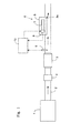
- Fig. 1 shows a schematic arrangement of an exhaust system of an internal combustion engine according to this embodiment.
- the internal combustion engine 1 is a diesel engine for driving a vehicle.
- An exhaust gas passage 2 is connected to the internal combustion engine 1.
- the inlet/outlet port for the exhaust gas is formed in only one direction in the sensor case 8. Accordingly, it is possible to suppress the flow of PM which is allowed to merely pass through the sensor case 8 simply without causing any collision against the PM sensor 7. Further, the inlet/outlet port is formed at the end portion disposed on the downstream side of the sensor case 8. Accordingly, PM, which exists in the sensor case 8, is hardly affected by the pressure of the main flow of the exhaust gas in the exhaust gas passage 2. Therefore, the thermal phoresis of PM is performed more easily as described later on.
- the sensor case 8 When the inlet/outlet port 8a for the exhaust gas is formed at the end portion on the upstream side of the portion of the sensor case 8 positioned in the exhaust gas passage 2 as in this modified embodiment, as shown in Fig. 10 , the sensor case 8 may be installed while being inclined toward the upstream side (i.e., the position of the end portion on the upstream side is lower than the position of the end portion on the downstream side). Accordingly, when any condensed water is produced in the sensor case 8, the condensed water can be discharged from the inlet/outlet port 8a for the exhaust gas.
Landscapes
- Chemical & Material Sciences (AREA)
- Analytical Chemistry (AREA)
- Engineering & Computer Science (AREA)
- General Physics & Mathematics (AREA)
- Biochemistry (AREA)
- Pathology (AREA)
- Immunology (AREA)
- Physics & Mathematics (AREA)
- Health & Medical Sciences (AREA)
- Life Sciences & Earth Sciences (AREA)
- General Health & Medical Sciences (AREA)
- Dispersion Chemistry (AREA)
- Mechanical Engineering (AREA)
- Combustion & Propulsion (AREA)
- General Engineering & Computer Science (AREA)
- Chemical Kinetics & Catalysis (AREA)
- Electrochemistry (AREA)
- Exhaust Gas After Treatment (AREA)
- Processes For Solid Components From Exhaust (AREA)
Abstract
Description
- The present invention relates to a PM amount detecting apparatus for detecting an amount of particulate matter (hereinafter referred to as "PM") contained in an exhaust gas of an internal combustion engine.
- A technique is known, in which a PM amount contained in an exhaust gas of an internal combustion engine is detected by a PM sensor.
Patent Document 1 discloses a PM sensor (particulate sensor) provided with at least two electrodes. The PM sensor detects or senses a particulate deposition amount in the PM sensor from the measurement data of the electric characteristic including, for example, the AC impedance between the electrodes. Further,Patent Document 1 describes a technique in which the PM sensor is installed in particulate collecting means which collects PM on a part of a cross section perpendicular to a gas flow passage or on a second flow passage different from the gas flow passage. - Techniques, which relate to PM sensors, are also described in
Patent Documents 2 to 5. -
- Patent Document 1: Japanese patent application laid-open No.
2008-064621 - Patent Document 2: Japanese patent application laid-open No.
2008-190502 - Patent Document 3:
WO2008/117853A ; - Patent Document 4: Japanese patent application laid-open No.
2008-115765 - Patent Document 5: Japanese patent application laid-open No.
08-068313 - In order to detect the PM amount contained in the exhaust gas of the internal combustion engine, a PM sensor is used in some cases, which outputs a signal corresponding to the PM amount deposited or deposited on the sensor itself. The PM sensor as described above is generally installed in an exhaust gas passage. PM contained in the exhaust gas adheres to the PM sensor installed in the exhaust gas passage. Adhered PM is gradually deposited in the PM sensor. The output value of the PM sensor is changed depending on the increase in the PM deposition amount.
- As for the PM sensor, PM, which collides with the PM sensor, is adhered to and deposited in the PM sensor. However, PM, which does not collide with the PM sensor, exists in the exhaust gas, and PM, which does not adhere to the PM sensor even when PM collides with the PM sensor, exists in the exhaust gas. When the flow rate of the exhaust gas is raised, the flow rate of PM is increased as well. When the flow rate of PM is increased, then the PM amount itself adhered to the PM sensor is increased, but there is such a tendency that the PM collection ratio in the PM sensor (i.e., ratio of the PM amount adhered to the PM sensor with respect to the flow rate of PM) is lowered. If the PM collection ratio becomes unstable in the PM sensor resulting from the fact as described above, it is feared that it may be difficult to correctly detect the PM amount in the exhaust gas on the basis of the output value of the PM sensor.
- The present invention has been made taking the foregoing problem into consideration, an object of which is to provide a technique which makes it possible to detect a PM amount in an exhaust gas of an internal combustion engine more highly accurately.
- The present invention adopts the following means in order to solve the problem as described above. That is, in the present invention, a PM sensor is installed in a sensor case, and thus it is intended that the flow rate of an exhaust gas is lowered around the PM sensor and PM is guided (introduced or induced) to the PM sensor in accordance with the thermal phoresis.
- In particular, the PM amount detecting apparatus according to the present invention resides in a PM amount detecting apparatus which is provided for an exhaust gas passage of an internal combustion engine and which detects an amount of particulate matter contained in an exhaust gas, the PM amount detecting apparatus comprising:
- a PM sensor which outputs a signal corresponding to the amount of the particulate matter deposited in the PM sensor itself; and
- a sensor case which includes the PM sensor installed therein and into which a part of the exhaust gas allowed to flow through the exhaust gas passage is intaken, the sensor case having a structure which lowers a flow rate of the exhaust gas therein to such an extent that the particulate matter is capable of performing thermal phoresis, and a structure which generates therein such a temperature difference that the particulate matter is guided to the PM sensor in accordance with the thermal phoresis.
- According to the present invention, the flow rate of the exhaust gas is reduced in the sensor case, and PM is guided (introduced or induced) to the PM sensor in accordance with the thermal phoresis. Accordingly, PM in the exhaust gas tends to adhere to the PM sensor with ease. Therefore, the PM collection ratio can be stably maintained to be high in the PM sensor irrelevant to the flow rate of the exhaust gas in the exhaust gas passage. As a result, the PM amount in the exhaust gas can be detected more highly accurately on the basis of the output value of the PM sensor.
- The "structure which lowers the flow rate of the exhaust gas therein to such an extent that the particulate matter is capable of performing the thermal phoresis" of the sensor case according to the present invention can be realized by the installation position and the shape of the sensor case or the position and the shape of the inlet/outlet port for the exhaust gas formed for the sensor case.
- For example, the inlet/outlet port for the exhaust gas, which is provided for the sensor case, may be formed in only one direction. Accordingly, the flow of the exhaust gas, which inflows into the sensor case in a certain direction and which outflows into the exhaust gas passage in another direction, can be suppressed in the sensor case. Therefore, the flow rate of the exhaust gas in the sensor case can be lowered to such an extent that the thermal phoresis of PM can be performed. Further, the inlet/outlet port for the exhaust gas may be formed at only an end portion of the sensor case disposed on a downstream side. Accordingly, the influence of the pressure of the main flow of the exhaust gas allowed to flow through the exhaust gas passage is hardly exerted on PM existing in the sensor case. Therefore, PM is subjected to the thermal phoresis more easily.
- The "structure which generates therein such a temperature difference that the particulate matter is guided to the PM sensor in accordance with the thermal phoresis" of the sensor case according to the present invention can be realized by the installation position of the sensor case and the installation position of the PM sensor in the sensor case. This structure can be also realized by providing at least any one of a heating device and a cooling device for the sensor case.
- The structure as described above may be such a "structure that a temperature of the PM sensor is lowered as compared with a temperature of at least a part of a wall surface of the sensor case". According to this structure, PM contained in the exhaust gas in the sensor case is guided to the PM sensor in accordance with the thermal phoresis. Alternatively, the structure as described above may be such a "structure that the temperature difference is generated between wall surfaces which are opposed to one another while interposing the PM sensor". According to this structure, PM contained in the exhaust gas in the sensor case is moved from the side of the wall surface having a high temperature to the side of the wall surface having a low temperature in accordance with the thermal phoresis. In this situation, the PM sensor is positioned on the route of movement of PM. Therefore, PM is guided to the PM sensor.
- In the present invention, for example, the sensor case may be installed so that a part thereof is positioned in the exhaust gas passage and another part is positioned outside the exhaust gas passage. Accordingly, the temperature of the wall surface of the portion of the sensor case positioned outside the exhaust gas passage is lower than the temperature of the wall surface of the portion of the sensor case positioned in the exhaust gas passage. In this arrangement, the PM sensor may be arranged at a portion which is positioned outside the exhaust gas passage in the sensor case. Alternatively, the PM sensor may be arranged at a portion which is positioned in the exhaust gas passage in the sensor case in the vicinity of a position of a wall surface of the exhaust gas passage. Accordingly, the temperature of the PM sensor can be lowered as compared with the temperature of the wall surface of the portion of the sensor case positioned in the exhaust gas passage. Further, it is possible to generate the temperature difference between the wall surfaces of the sensor case which are opposed to one another while interposing the PM sensor.
- In the case of the arrangement as described above, it is also allowable to provide a heating device which heats a wall surface of a portion of the sensor case positioned in the exhaust gas passage. Further, in the case of the arrangement as described above, it is also allowable to provide a cooling device which cools a wall surface of a portion of the sensor case positioned outside the exhaust gas passage. According to these arrangements, it is possible to further increase the temperature difference between the wall surfaces of the sensor case or the temperature difference between the wall surface of the sensor case and the PM sensor. As a result, it is possible to accelerate the guided movement (introduction or induction) of PM to the PM sensor in accordance with the thermal phoresis.
- The heating device can be realized by providing a heat receiving fin which receives heat of the exhaust gas allowed to flow through the exhaust gas passage, at a portion of the sensor case positioned in the exhaust gas passage. Further, the cooling device can be realized by providing a heat releasing fin which releases heat of the exhaust gas in the sensor case to outside, at a portion of the sensor case positioned outside the exhaust gas passage.
- In the present invention, the sensor case may be installed so that at least a part thereof is positioned in the exhaust gas passage. Further, a catalyst, which has an oxidation function, may be provided at a portion positioned in the exhaust gas passage, the portion being a part of an outer wall surface of the sensor case. In this arrangement, the fuel component contained in the exhaust gas, which is allowed to flow through the exhaust gas passage, is oxidized on the catalyst. Therefore, the wall surface of the portion of the sensor case, which is provided with the catalyst, is heated by the heat of oxidation. Therefore, it is possible to lower the temperature of the wall surface of the portion of the sensor case opposed to the portion of installation of the catalyst while interposing the PM sensor, as compared with the temperature of the wall surface of the portion of the sensor case provided with the catalyst. Further, it is possible to lower the temperature of the PM sensor as compared with the temperature of the wall surface of the portion of the sensor case provided with the catalyst.
- In the present invention, the sensor case may be provided with a heating device which heats a part of a wall surface of the sensor case. Accordingly, it is possible to lower the temperature of the portion of the wall surface of the sensor case opposed to the heated portion while interposing the PM sensor as compared with the temperature of the portion of the wall surface of the sensor case heated by the heating device. Further, it is possible to lower the temperature of the PM sensor as compared with the temperature of the portion of the wall surface of the sensor case heated by the heating device.
- In the case of the arrangement as described above, the sensor case may further include a cooling device which cools a portion of the wall surface thereof opposed to a portion heated by the heating device while interposing the PM sensor. Accordingly, it is possible to further increase the temperature difference between the wall surfaces opposed to one another while interposing the PM sensor. As a result, it is possible to accelerate the guided movement (introduction or induction) of PM to the PM sensor in accordance with the thermal phoresis.
- The respective means described above can be combined with each other as far as possible.
- According to the present invention, it is possible to detect the PM amount contained in the exhaust gas of the internal combustion engine by means of the PM sensor more highly accurately.
-
-
Fig. 1 shows a schematic arrangement of an exhaust system of an internal combustion engine according to a first embodiment. -
Fig. 2 shows a schematic arrangement of a PM sensor according to the first embodiment. -
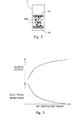
Fig. 3 shows a graph illustrating a relationship among the PM deposition amount in the PM sensor, the electrical resistance between electrodes of the PM sensor, and the output value of the PM sensor. -
Fig. 4 shows a first graph illustrating a relationship between the flow rate of an exhaust gas in an exhaust gas passage and the PM collection ratio in the PM sensor. -
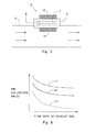
Fig. 5 shows a schematic arrangement of a PM amount detecting apparatus according to a first modified embodiment of the first embodiment. -
Fig. 6 shows a second graph illustrating a relationship between the flow rate of an exhaust gas in an exhaust gas passage and the PM collection ratio in a PM sensor. -
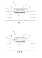
Fig. 7 shows a schematic arrangement of a PM amount detecting apparatus according to a second modified embodiment of the first embodiment. -
Fig. 8 shows a schematic arrangement of a PM amount detecting apparatus according to a third modified embodiment of the first embodiment. -
Fig. 9 shows a first drawing illustrating a schematic arrangement of a PM amount detecting apparatus according to a fourth modified embodiment of the first embodiment. -
Fig. 10 shows a second drawing illustrating a schematic arrangement of a PM amount detecting apparatus according to the fourth modified embodiment of the first embodiment. -
Fig. 11 shows a third drawing illustrating a schematic arrangement of a PM amount detecting apparatus according to the fourth modified embodiment of the first embodiment. -
Fig. 12 shows a schematic arrangement of a PM amount detecting apparatus according to a second embodiment. -
Fig. 13 shows a schematic arrangement of a PM amount detecting apparatus according to a third embodiment. -
Fig. 14 shows a schematic arrangement of a PM amount detecting apparatus according to a modified embodiment of the third embodiment. -
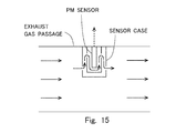
Fig. 15 shows a schematic arrangement of a conventional PM amount detecting apparatus. - Specified embodiments of the present invention will be explained below on the basis of the drawings. For example, sizes (dimensions), materials, and shapes of constitutive parts or components as well as relative arrangements thereof, which are described in the embodiments of the present invention, are not intended to limit the technical scope of the invention only thereto, unless otherwise specified.
- A first embodiment of the present invention will be explained on the basis of
Figs. 1 to 10 . In this embodiment, an explanation will be made about a case in which the present invention is applied in order to detect the PM amount contained in an exhaust gas of a diesel engine for driving a vehicle. The internal combustion engine according to the present invention is not limited to the diesel engine. The internal combustion engine may be a gasoline engine. -
Fig. 1 shows a schematic arrangement of an exhaust system of an internal combustion engine according to this embodiment. Theinternal combustion engine 1 is a diesel engine for driving a vehicle. Anexhaust gas passage 2 is connected to theinternal combustion engine 1. - A particulate filter (hereinafter referred to as "DPF") 3, which collects PM contained in an exhaust gas, is provided in the
exhaust gas passage 2. Anoxidation catalyst 4 is provided on the upstream side fromDPF 3 in theexhaust gas passage 2. Atemperature sensor 5 for detecting the temperature of the exhaust gas and a PMamount detecting apparatus 6 for detecting the PM amount contained in the exhaust gas are provided for theexhaust gas passage 2 at portions disposed on the downstream side fromDPF 3 in theexhaust gas passage 2. The PMamount detecting apparatus 6 is provided with aPM sensor 7 and asensor case 8. Details of the PMamount detecting apparatus 6 will be described later on. - An electronic control unit (ECU) 10 is provided in combination with the
internal combustion engine 1.ECU 10 is a unit which controls, for example, the operation state of theinternal combustion engine 1. Thetemperature sensor 5 and thePM sensor 7 are electrically connected toECU 10. In addition thereto, those electrically connected toECU 10 are various sensors including, for example, an air flow meter, a crank position sensor, and an accelerator opening degree sensor (not shown). - In this embodiment, the filter regeneration process (reproduction process), in which PM deposited or deposited in
DPF 3 is oxidized and removed, is performed when a predetermined condition is established. In the filter regeneration process, the temperature ofDPF 3 is raised to a target temperature at which deposited PM can be oxidized. The method for raising the temperature ofDPF 3 is exemplified, for example, by a method in which the fuel is supplied to theoxidation catalyst 4 by performing the auxiliary fuel injection (sub-fuel injection) in theinternal combustion engine 1, and the temperature of the exhaust gas allowed to inflow intoDPF 3 is raised by using the heat of oxidation generated by the oxidation of the fuel in theoxidation catalyst 4. The temperature ofDPF 3 is estimated on the basis of the detected value of thetemperature sensor 5 when the filter regeneration process is executed. - Any abnormal situation, which includes, for example, the breakage and the dissolution loss, is caused in some cases due to the thermal deterioration and/or the time-dependent deterioration in
DPF 3. If such an abnormal situation arises inDPF 3, the amount of PM, which outflows to the downstream side without being collected byDPF 3, is increased. In view of the above, in this embodiment, the detection of the abnormal situation ofDPF 3 is carried out on the basis of the PM amount contained in the exhaust gas detected by the PMamount detecting apparatus 6. Therefore, in order to correctly detect the abnormal situation ofDPF 3, it is necessary that the PM amount in the exhaust gas should be detected highly accurately by means of the PMamount detecting apparatus 6. -
Fig. 2 shows a schematic arrangement of thePM sensor 7. As shown inFig. 2 , thePM sensor 7 is provided with a pair ofelectrodes Fig. 3 shows a graph illustrating a relationship among the PM deposition amount in thePM sensor 7, the electrical resistance between theelectrodes PM sensor 7, and the output value of thePM sensor 7. With reference toFig. 3 , the horizontal axis represents the PM deposition amount in thePM sensor 7, the vertical axis of the lower part represents the electrical resistance between theelectrodes PM sensor 7, and the vertical axis of the upper part represents the output value of thePM sensor 7. - PM in the exhaust gas adheres to the
PM sensor 7, and PM is deposited between theelectrodes Fig. 3 , as the PM deposition amount in thePM sensor 7 is increased, the electrical resistance between theelectrodes electrodes PM sensor 7 is increased. Therefore, the output value of thePM sensor 7 is the value corresponding to the added-up value of the PM flow rate. Further, the PM flow rate can be also calculated by differentiating the output value of thePM sensor 7. - An
electric heater 9 is provided for thePM sensor 7. If PM is excessively deposited in thePM sensor 7, it is difficult to correctly detect the PM amount in the exhaust gas on the basis of the output value thereof. In view of the above, when the PM deposition amount in thePM sensor 7 arrives at a certain amount, then thePM sensor 7 is heated by theelectric heater 9, and thus PM, which is deposited in thePM sensor 7, is oxidized and removed. Theelectric heater 9 is electrically connected toECU 10. The operation of theelectric heater 9 is controlled byECU 10. - The
PM sensor 7 according to this embodiment is not limited to the structure or arrangement as described above. Any known PM sensor may be used as thePM sensor 7 provided that the PM sensor outputs the signal corresponding to the PM amount deposited in the sensor itself. For example, the PM amount, which is deposited in the PM sensor itself, may be estimated on the basis of the amount of increase in the temperature of the PM sensor as obtained when PM, which is deposited in the PM sensor, is combusted and removed by heating the PM sensor by means of the electric heater. - In this embodiment, the
PM sensor 7 as described above is installed in thesensor case 8. In this embodiment, as shown inFig. 1 , thesensor case 8 is installed so that a part thereof is positioned in theexhaust gas passage 2, and another part is positioned outside theexhaust gas passage 2. An inlet/outlet port 8a for the exhaust gas is formed at an end portion disposed on the downstream side of a portion of thesensor case 8 positioned in theexhaust gas passage 2. A part of the exhaust gas allowed to flow through theexhaust gas passage 2 is allowed to inflow into thesensor case 8 from the inlet/outlet port 8a. The exhaust gas, which is once allowed to inflow into thesensor case 8, is allowed to outflow to the inside of theexhaust gas passage 2 from the inlet/outlet port 8a (inFig. 1 , the arrows indicate the flow of the exhaust gas). The inlet and the outlet for the exhaust gas of thesensor case 8 according to this embodiment are only the inlet/outlet port 8a. The exhaust gas, which is allowed to flow through theexhaust gas passage 2, is pulsed. Therefore, even when the inlet/outlet port 8a for the exhaust gas is formed at the end portion disposed on the downstream side of thesensor case 8, the exhaust gas can enter and exit between theexhaust gas passage 2 and thesensor case 8. - Further, as shown in
Fig. 1 , thePM sensor 7 is arranged at the portion positioned outside theexhaust gas passage 2 in the sensor case 8 (i.e., at the portion disposed over the broken line in thesensor case 8 as shown inFig. 1 ). Further, in thesensor case 8, thePM sensor 7 is installed in such a state that the axial direction thereof is substantially parallel to the axial direction of the exhaust gas passage 2 (i.e., in such a state that thePM sensor 7 falls in the lateral direction as shown inFig. 1 ). - An explanation will now be made about the excellent points or features of the PM amount detecting apparatus according to this embodiment as compared with a conventional case.
Fig. 15 shows a schematic arrangement of a conventional PM amount detecting apparatus. Also in the case of the conventional technique, a PM sensor is installed in a sensor case in the same manner as in this embodiment. However, in the case of the conventional technique, the entire sensor case is positioned in the exhaust gas passage. Further, an exhaust gas inlet is formed on a wall surface disposed on the upstream side of the sensor case, and an exhaust gas outlet is formed on a wall surface disposed on the downstream side of the sensor case (inFig. 15 , the arrows indicate the flow of the exhaust gas). - According to the conventional structure or arrangement as described above, the flow of the exhaust gas, which is directed from the upstream side to the downstream side and which is in the same direction as that of the flow of the exhaust gas in the exhaust gas passage, is also generated in the sensor case. Therefore, a large amount of PM exists, which outflows from the sensor case without colliding against or adhering to the PM sensor even when PM inflows into the sensor case. Further, when the flow rate of the exhaust gas is raised in the exhaust gas passage, the flow rate of the exhaust gas is also raised in the sensor case. Therefore, the PM collection ratio is lowered in the PM sensor.
- On the contrary, in the case of the PM
amount detecting apparatus 6 according to this embodiment, the inlet/outlet port 8a for the exhaust gas is formed at only the end portion disposed on the downstream side of thesensor case 8. Accordingly, the flow rate of the exhaust gas in thesensor case 8 can be made extremely small as compared with the flow rate of the exhaust gas in theexhaust gas passage 2. Further, even when the flow rate of the exhaust gas is raised in theexhaust gas passage 2, it is possible to suppress the increase in the flow rate of the exhaust gas in thesensor case 8. That is, according to thesensor case 8 constructed as described above, the flow rate of the exhaust gas in thesensor case 8 can be lowered to such an extent that the thermal phoresis of PM can be performed as described later on. - Further, the inlet/outlet port for the exhaust gas is formed in only one direction in the
sensor case 8. Accordingly, it is possible to suppress the flow of PM which is allowed to merely pass through thesensor case 8 simply without causing any collision against thePM sensor 7. Further, the inlet/outlet port is formed at the end portion disposed on the downstream side of thesensor case 8. Accordingly, PM, which exists in thesensor case 8, is hardly affected by the pressure of the main flow of the exhaust gas in theexhaust gas passage 2. Therefore, the thermal phoresis of PM is performed more easily as described later on. - Further, in the PM
amount detecting apparatus 6 according to this embodiment, as described above, thePM sensor 7 is installed so that thePM sensor 7 is positioned outside theexhaust gas passage 2 in thesensor case 8. The portion of thesensor case 8, which is positioned outside theexhaust gas passage 2, is cooled by the outside air. Therefore, the temperature of thePM sensor 7 is suppressed from being raised. Therefore, the temperature of thePM sensor 7 is lower than the temperature of the wall surface of the portion of thesensor case 8 positioned in the exhaust gas passage 2 (hereinafter referred to as "wall surface on the exhaust gas passage side"), and it is possible to maintain the temperature difference. When the temperature difference is generated as described above in a state in which the flow rate of the exhaust gas is sufficiently lowered in thesensor case 8, PM, which exists between thePM sensor 7 and the wall surface on the exhaust gas passage side, is guided to thePM sensor 7 in accordance with the thermal phoresis. - It is not necessarily indispensable that the
PM sensor 7 should be positioned outside theexhaust gas passage 2 in thesensor case 8, provided that the temperature of thePM sensor 7 is sufficiently lower than the temperature of the wall surface on the exhaust gas passage side of thesensor case 8. Even if thePM sensor 7 is installed at the portion positioned in theexhaust gas passage 2 in thesensor case 8, when thePM sensor 7 is installed at any position disposed near to the position of the wall surface of theexhaust gas passage 2, then the temperature of thePM sensor 7 can be made sufficiently lower than the temperature of the wall surface on the exhaust gas passage side. - In the
sensor case 8, the temperature difference also arises between the wall surface on the exhaust gas passage side and the wall surface (hereinafter referred to as "wall surface on the outer side") which is positioned outside theexhaust gas passage 2 and which is opposed to the wall surface on the exhaust gas passage side while interposing thePM sensor 7. That is, the temperature of the wall surface on the outer side is lower than the temperature of the wall surface on the exhaust gas passage side. Further, the temperature difference is maintained. When the temperature difference arises as described above in a state in which the flow rate of the exhaust gas is sufficiently lowered in thesensor case 8, the movement of PM also arises, which is directed from the side of the wall surface on the exhaust gas passage side to the side of the wall surface on the outer side in accordance with the thermal phoresis. In this situation, thePM sensor 7 is installed so that the axis thereof extends along the both wall surfaces. Therefore, thePM sensor 7 is positioned on the route of the movement of PM. Therefore, PM, which is moved as described above, is also guided to thePM sensor 7. - PM is guided to the
PM sensor 7 in accordance with the thermal phoresis as described above, and thus it is possible to accelerate the adhesion of PM to thePM sensor 7. Therefore, according to the PM amount detecting apparatus concerning this embodiment, the PM collection ratio in thePM sensor 7 can be stably maintained to be high irrelevant to the flow rate of the exhaust gas in theexhaust gas passage 2. As a result, the PM amount in the exhaust gas can be detected more highly accurately on the basis of the output value of thePM sensor 7. -
Fig. 4 shows a graph illustrating a relationship between the flow rate of the exhaust gas in the exhaust gas passage and the PM collection ratio in the PM sensor. With reference toFig. 4 , a broken line L1 indicates the PM collection ratio in the conventional PM sensor shown inFig. 15 , and a solid line L2 indicates the PM collection ratio in the PM sensor according to this embodiment. As shown inFig. 4 , according to this embodiment, it is possible to improve the PM collection ratio in the PM sensor as compared with the conventional technique. In particular, when the flow rate of the exhaust gas is raised in the exhaust gas passage, it is possible to greatly improve the PM collection ratio in the PM sensor as compared with the conventional technique. - Modified embodiments of the embodiment of the present invention will be explained with reference to
Figs. 5 to 11 . Only the points or features, which are different from those of the embodiment described above, will be explained herein. InFigs. 5 and7 to 10 , the arrows indicate the flow of the exhaust gas. -
Fig. 5 shows a schematic arrangement of a PM amount detecting apparatus according to a first modified embodiment of the embodiment of the present invention. In this modified embodiment, aheat receiving fin 11 is provided on the wall surface on the exhaust gas passage side of thesensor case 8. Theheat receiving fin 11 receives the heat of the exhaust gas allowed to flow through theexhaust gas passage 2. Accordingly, it is possible to accelerate the heating of the wall surface on the exhaust gas passage side of thesensor case 8 by means of the exhaust gas. - Further, a
heat releasing fin 12 is provided on the wall surface on the outer side of thesensor case 8. Theheat releasing fin 12 releases the heat of the exhaust gas contained in thesensor case 8 to the outside. Accordingly, it is possible to accelerate the cooling of the wall surface on the outer side of thesensor case 8 by means of the outside air. It is also allowable to enhance the cooling effect on the wall surface on the outer side of thesensor case 8 by performing the heat exchange, for example, with cooling water. - According to this modified embodiment, it is possible to further increase the temperature difference between the
PM sensor 7 and the wall surface on the exhaust gas passage side of thesensor case 8 and the temperature difference between the wall surface on the outer side and the wall surface on the exhaust gas passage side of thesensor case 8. As a result, it is possible to accelerate the guided movement (introduction or induction) of PM to thePM sensor 7 by means of the thermal phoresis: -
Fig. 6 shows a graph illustrating a relationship between the flow rate of the exhaust gas in the exhaust gas passage and the PM collection ratio in the PM sensor. With reference toFig. 6 , a broken line L1 indicates the PM collection ratio in the conventional PM sensor shown inFig. 15 , a solid line L2 indicates the PM collection ratio in the PM sensor according to the embodiment described above, and an alternate long and short dash line L3 indicates the PM collection ratio in the PM sensor according to this modified embodiment. As shown inFig. 6 , according to this modified embodiment, the PM collection ratio can be further improved in thePM sensor 7 as compared with the cases in which theheat receiving fin 11 and theheat releasing fin 12 are not provided for thesensor case 8. - It is not necessarily indispensable that both of the
heat receiving fin 11 and theheat releasing fin 12 should be provided for thesensor case 8. Even when only any one of theheat receiving fin 11 and theheat releasing fin 12 is provided for thesensor case 8, it is possible to increase the temperature difference between thePM sensor 7 and the wall surface on the exhaust gas passage side of thesensor case 8 and the temperature difference between the wall surface on the outer side and the wall surface on the exhaust gas passage side of thesensor case 8, as compared with the structure or arrangement in which thefin -
Fig. 7 shows a schematic arrangement of a PM amount detecting apparatus according to a second modified embodiment of the embodiment of the present invention. In this modified embodiment, acatalyst 13 is provided on the outer side of the wall surface on the exhaust gas passage side of thesensor case 8. Thecatalyst 13 is a catalyst (for example, an oxidation catalyst) which has the oxidation function. The fuel component (HC) contained in the exhaust gas, which is allowed to flow through theexhaust gas passage 2, is oxidized on thecatalyst 13. The heating of the wall surface on the exhaust gas passage side of thesensor case 8 is accelerated by the heat of oxidation generated in this situation. - According to this modified embodiment, it is also possible to further increase the temperature difference between the
PM sensor 7 and the wall surface on the exhaust gas passage side of thesensor case 8 and the temperature difference between the wall surface on the outer side and the wall surface on the exhaust gas passage side of thesensor case 8 in the same manner as in the first modified embodiment. As a result, it is possible to accelerate the guided movement (introduction or induction) of PM to thePM sensor 7 in accordance with the thermal phoresis. Therefore, it is possible to further improve the PM collection ratio in thePM sensor 7 as compared with the case in which thecatalyst 13 is not provided for thesensor case 8. -
Fig. 8 shows a schematic arrangement of a PM amount detecting apparatus according to a third modified embodiment of the embodiment of the present invention. In this modified embodiment, anelectric heater 14 is provided, which heats the wall surface on the exhaust gas passage side of thesensor case 8. Theelectric heater 14 is electrically connected toECU 10. The operation of theelectric heater 14 is controlled byECU 10. - According to this modified embodiment, it is also possible to further increase the temperature difference between the
PM sensor 7 and the wall surface on the exhaust gas passage side of thesensor case 8 and the temperature difference between the wall surface on the outer side and the wall surface on the exhaust gas passage side of thesensor case 8 in the same manner as in the first and second modified embodiments, by heating the wall surface on the exhaust gas passage side by means of theelectric heater 14. As a result, it is possible to accelerate the guided movement (introduction or induction) of PM to thePM sensor 7 in accordance with the thermal phoresis. Therefore, it is possible to further improve the PM collection ratio in thePM sensor 7 as compared with the case in which theelectric heater 14 is not provided for thesensor case 8. - In the second and third modified embodiments, it is also allowable to provide a heat releasing fin on the wall surface on the outer side of the
sensor case 8 in the same manner as in the first modified embodiment. Accordingly, it is possible to further increase the temperature difference in thesensor case 8 as described above. -
Figs. 9 to 11 show schematic arrangements of PM amount detecting apparatuses according to a fourth modified embodiment of the embodiment of the present invention. In this modified embodiment, as shown inFig. 9 , an inlet/outlet port 8a for the exhaust gas is formed at an end portion on the upstream side of a portion of thesensor case 8 positioned in theexhaust gas passage 2. In thesensor case 8 according to this modified embodiment, the inlet and the outlet for the exhaust gas are only the inlet/outlet port 8a. - Even in the case of the arrangement as described above, the exhaust gas, which inflows from the inlet/
outlet port 8a into thesensor case 8, is suppressed from passing through the inside of thesensor case 8 as it is and outflowing into theexhaust gas passage 2 from the downstream side of thesensor case 8. Therefore, the flow rate of the exhaust gas in thesensor case 8 can be decreased as compared with the flow rate of the exhaust gas in theexhaust gas passage 2 in the same manner as in the case in which the inlet/outlet port 8a for the exhaust gas is formed at the end portion on the downstream side of thesensor case 8. Further, even when the flow rate of the exhaust gas is raised in theexhaust gas passage 2, it is possible to suppress the increase in the flow rate of the exhaust gas in thesensor case 8. That is, the flow rate of the exhaust gas in thesensor case 8 can be lowered to such an extent that the thermal phoresis of PM can be performed. Further, it is possible to suppress the flow of PM which merely passes through the inside of thesensor case 8 simply without colliding with thePM sensor 7. - When the inlet/
outlet port 8a for the exhaust gas is formed at the end portion on the upstream side of the portion of thesensor case 8 positioned in theexhaust gas passage 2 as in this modified embodiment, as shown inFig. 10 , thesensor case 8 may be installed while being inclined toward the upstream side (i.e., the position of the end portion on the upstream side is lower than the position of the end portion on the downstream side). Accordingly, when any condensed water is produced in thesensor case 8, the condensed water can be discharged from the inlet/outlet port 8a for the exhaust gas. - Further, as shown in
Fig. 11 , thesensor case 8 is sometimes in a state in which thesensor case 8 is inclined toward the downstream side as well, because theexhaust gas passage 2 is in an inclined state when the vehicle, which carries theinternal combustion engine 1, runs on the level ground or in the flat area, depending on the position of installation of the PMamount detecting apparatus 6 in the exhaust gas passage 2 (i.e., the position of the end portion on the upstream side is higher than the position of the end portion on the downstream side). In such a situation, adischarge port 8b, which is usable to discharge the condensed water from the inside of thesensor case 8, may be provided at an end portion on the downstream side of a portion of thesensor case 8 positioned in theexhaust gas passage 2. - In this arrangement, the size of the
discharge port 8b is made extremely small as compared with the inlet/outlet port 8a for the exhaust gas, in order to suppress the outflow of the exhaust gas from thedischarge port 8b into theexhaust gas passage 2. Accordingly, it is possible to suppress the increase in the flow rate of the exhaust gas in thesensor case 8, which would be otherwise caused by the provision of thedischarge port 8b for thesensor case 8. - A second embodiment of the present invention will be explained on the basis of
Fig. 12 . Only the points or features, which are different from those of the first embodiment, will be explained herein. -
Fig. 12 shows a schematic arrangement of a PM amount detecting apparatus according to this embodiment. As shown inFig. 12 , in this embodiment, the PMamount detecting apparatus 6 is provided outside theexhaust gas passage 2. That is, anentire sensor case 8 is positioned outside theexhaust gas passage 2. Further, the wall surface of thesensor case 8, which is disposed on the side of theexhaust gas passage 2, is brought in contact with the outer wall of theexhaust gas passage 2. Further, an inlet/outlet port 8a for the exhaust gas is formed at a portion of the wall surface of thesensor case 8 brought in contact with the outer wall of the exhaust gas passage 2 (inFig. 12 , the arrows indicate the flow of the exhaust gas). ThePM sensor 7 is installed in thesensor case 8 in such a state that the axial direction thereof intersects the axial direction of theexhaust gas passage 2 substantially perpendicularly. - Even when the PM
amount detecting apparatus 6 is constructed as described above, any one of the exhaust gas allowed to inflow into thesensor case 8 and the exhaust gas allowed to outflow from thesensor case 8 passes through the inlet/outlet port 8a. Therefore, the flow rate of the exhaust gas in thesensor case 8 can be made smaller than the flow rate of the exhaust gas in theexhaust gas passage 2 in the same manner as in the PM amount detecting apparatus according to the first embodiment. Further, even when the flow rate of the exhaust gas is raised in theexhaust gas passage 2, it is possible to suppress the increase in the flow rate of the exhaust gas in thesensor case 8. That is, it is possible to lower the flow rate of the exhaust gas in thesensor case 8 to such an extent that the thermal phoresis of PM can be performed. Further, the flow of PM, which merely passes through the inside of thesensor case 8 simply without colliding against thePM sensor 7, is suppressed. - Further, in this embodiment, the direction of the main flow of the exhaust gas in the
exhaust gas passage 2 is different from the direction of the flow of the exhaust gas allowed to inflow into thesensor case 8. Therefore, PM, which exists in thesensor case 8, is hardly affected by the pressure of the main flow of the exhaust gas in theexhaust gas passage 2. - Also in this embodiment, the
PM sensor 7 is positioned outside theexhaust gas passage 2. Therefore, the increase in the temperature of thePM sensor 7 is suppressed. Therefore, the temperature of thePM sensor 7 is lower than the temperature of the wall surface of the portion of thesensor case 8 brought in contact with theexhaust gas passage 2, and it is possible to maintain the temperature difference. - Therefore, also in the PM amount detecting apparatus according to this embodiment, PM is guided to the
PM sensor 7 in accordance with the thermal phoresis in thesensor case 8. Therefore, the PM collection ratio can be stably maintained to be high in thePM sensor 7 irrelevant to the flow rate of the exhaust gas in theexhaust gas passage 2. - A third embodiment of the present invention will be explained on the basis of
Figs. 13 and14 . Only the points or features, which are different from those of the second embodiment, will be explained herein. -
Fig. 13 shows a schematic arrangement of a PM amount detecting apparatus according to this embodiment. As shown inFig. 13 , in this embodiment, the PMamount detecting apparatus 6 is provided inside theexhaust gas passage 2. That is, anentire sensor case 8 is positioned inside theexhaust gas passage 2. The wall surface of thesensor case 8, which is disposed on the side of the inner wall of theexhaust gas passage 2, is brought in contact with the inner wall of theexhaust gas passage 2. An inlet/outlet port 8a for the exhaust gas is formed at the wall surface of thesensor case 8 opposed to the wall surface brought in contact with the inner wall of the exhaust gas passage 2 (inFig. 13 , the arrows indicate the flow of the exhaust gas). - A
catalyst 15 is provided on the outer side of the wall surface on the upstream side of thesensor case 8. Thecatalyst 15 is a catalyst (for example, an oxidation catalyst) which has the oxidation function. The fuel component (HC) contained in the exhaust gas, which is allowed to flow through theexhaust gas passage 2, is oxidized on thecatalyst 15. The heating of the wall surface on the upstream side of thesensor case 8 is accelerated by the heat of oxidation generated in this situation. - According to the structure or arrangement as described above concerning this embodiment, it is also possible to lower the flow rate of the exhaust gas in the
sensor case 8 to such an extent that the thermal phoresis of PM can be performed, for the same reason as that referred to in the second embodiment. Further, the flow of PM, which merely passes through the inside of thesensor case 8 simply without colliding against thePM sensor 7, is suppressed. Further, PM, which exists in thesensor case 8, is hardly affected by the pressure of the main flow of the exhaust gas in theexhaust gas passage 2. - The wall surface on the upstream side of the
sensor case 8 is heated by the heat of oxidation generated by thecatalyst 15, and thus the temperature difference arises between the wall surface and thePM sensor 7. That is, the temperature of thePM sensor 7 is lower than the temperature of the wall surface on the upstream side of thesensor case 8, and the temperature difference can be maintained. Further, the temperature difference also arises between the wall surface on the upstream side and the wall surface on the downstream side opposed to the wall surface on the upstream side while interposing thePM sensor 7 in thesensor case 8, and the temperature difference can be maintained. - Therefore, also in the PM amount detecting apparatus according to this embodiment, PM is guided to the
PM sensor 7 in accordance with the thermal phoresis in thesensor case 8. Therefore, the PM collection ratio can be stably maintained to be high in thePM sensor 7 irrelevant to the flow rate of the exhaust gas in theexhaust gas passage 2. - In this embodiment, a cooling device, which cools the wall surface by means of the heat exchange with cooling water or the like, may be further provided for the wall surface on the downstream side of the
sensor case 8. Accordingly, it is possible to further increase the temperature difference between the wall surface on the upstream side and the wall surface on the downstream side opposed thereto while interposing thePM sensor 7. Therefore, it is possible to further accelerate the guided movement (introduction or induction) of PM to thePM sensor 7 in accordance with the thermal phoresis. -
Fig. 14 shows a schematic arrangement of a PM amount detecting apparatus according to a modified embodiment of the embodiment of the present invention. As shown inFig. 14 , in this modified embodiment, anelectric heater 16, which heats a part of the wall surface of thesensor case 8, may be provided in thesensor case 8 in place of thecatalyst 15. Theelectric heater 16 is electrically connected toECU 10. The operation of theelectric heater 16 is controlled byECU 10. - When the part of the wall surface of the
sensor case 8 is heated by theelectric heater 16, then the temperature difference can be generated in the same manner as in the embodiment described above between the wall surface and thePM sensor 7 and between the wall surfaces opposed to one another while interposing thePM sensor 7 in thesensor case 8, and the temperature difference can be maintained. - Also in this modified embodiment, a cooling device, which cools the wall surface by means of the heat exchange with cooling water or the like, may be further provided for the wall surface opposed to the wall surface heated by the
electric heater 16 while interposing thePM sensor 7 in thesensor case 8. Accordingly, it is possible to further increase the temperature difference between the wall surfaces opposed to one another while interposing thePM sensor 7 in thesensor case 8. - The respective embodiments described above can be combined with each other as far as possible.
-
- 1:
- internal combustion engine
- 2:
- exhaust gas passage
- 3:
- particulate filter
- 4:
- oxidation catalyst
- 5:
- temperature sensor
- 6:
- PM amount detecting apparatus
- 7:
- PM sensor
- 7a, 7b:
- electrode
- 8:
- sensor case
- 9, 14, 16:
- electric heater
- 10:
- ECU
- 11:
- heat receiving fin
- 12:
- heat releasing fin
- 13, 15:
- catalyst
Claims (11)
- A PM amount detecting apparatus which is provided for an exhaust gas passage of an internal combustion engine and which detects an amount of particulate matter contained in an exhaust gas, the PM amount detecting apparatus comprising:a PM sensor which outputs a signal corresponding to the amount of the particulate matter deposited in the PM sensor itself; anda sensor case which includes the PM sensor installed therein and into which a part of the exhaust gas allowed to flow through the exhaust gas passage is intaken, the sensor case having a structure which lowers a flow rate of the exhaust gas therein to such an extent that the particulate matter is capable of performing thermal phoresis, and a structure which generates therein such a temperature difference that the particulate matter is guided to the PM sensor in accordance with the thermal phoresis.
- The PM amount detecting apparatus according to claim 1, wherein the sensor case has such a structure that a temperature of the PM sensor is lowered as compared with a temperature of at least a part of a wall surface of the sensor case.
- The PM amount detecting apparatus according to claim 1, wherein the sensor case has such a structure that the temperature difference is generated between wall surfaces which are opposed to one another while interposing the PM sensor.
- The PM amount detecting apparatus according to any one of claims 1 to 3, wherein:the sensor case is installed so that a part thereof is positioned in the exhaust gas passage and another part is positioned outside the exhaust gas passage; andthe PM sensor is arranged at a portion which is positioned outside the exhaust gas passage in the sensor case or at a portion which is positioned in the exhaust gas passage in the sensor case in the vicinity of a position of a wall surface of the exhaust gas passage.
- The PM amount detecting apparatus according to claim 4, wherein the sensor case has at least any one of a heating device which heats a wall surface of a portion of the sensor case positioned in the exhaust gas passage and a cooling device which cools a wall surface of a portion of the sensor case positioned outside the exhaust gas passage.
- The PM amount detecting apparatus according to claim 5, wherein the heating device is a heat receiving fin which receives heat of the exhaust gas allowed to flow through the exhaust gas passage, and the cooling device is a heat releasing fin which releases heat of the exhaust gas in the sensor case to outside.
- The PM amount detecting apparatus according to any one of claims 1 to 3, wherein the sensor case is installed so that at least a part thereof is positioned in the exhaust gas passage, and the apparatus includes a catalyst which has an oxidation function and which is provided at a portion positioned in the exhaust gas passage, the portion being a part of an outer wall surface of the sensor case.
- The PM amount detecting apparatus according to any one of claims 1 to 3, wherein the sensor case has a heating device which heats a part of a wall surface of the sensor case.
- The PM amount detecting apparatus according to claim 8, wherein the sensor case further includes a cooling device which cools a portion of the wall surface of the sensor case opposed to a portion heated by the heating device while interposing the PM sensor.
- The PM amount detecting apparatus according to any one of claims 1 to 9, wherein the sensor case has an inlet/outlet port for the exhaust gas which is formed in only one direction.
- The PM amount detecting apparatus according to claim 10, wherein the inlet/outlet port for the exhaust gas is formed at only an end portion of the sensor case disposed on a downstream side.
Applications Claiming Priority (1)
| Application Number | Priority Date | Filing Date | Title |
|---|---|---|---|
| PCT/JP2010/057687 WO2011135717A1 (en) | 2010-04-30 | 2010-04-30 | Particulate matter quantity detection apparatus |
Publications (2)
| Publication Number | Publication Date |
|---|---|
| EP2565404A1 true EP2565404A1 (en) | 2013-03-06 |
| EP2565404A4 EP2565404A4 (en) | 2014-08-13 |
Family
ID=44861056
Family Applications (1)
| Application Number | Title | Priority Date | Filing Date |
|---|---|---|---|
| EP10850732.8A Ceased EP2565404A4 (en) | 2010-04-30 | 2010-04-30 | APPARATUS FOR DETECTING THE QUANTITY OF PARTICULATE MATTER |
Country Status (5)
| Country | Link |
|---|---|
| US (1) | US8966956B2 (en) |
| EP (1) | EP2565404A4 (en) |
| JP (1) | JP5429368B2 (en) |
| CN (1) | CN102985644B (en) |
| WO (1) | WO2011135717A1 (en) |
Families Citing this family (14)
| Publication number | Priority date | Publication date | Assignee | Title |
|---|---|---|---|---|
| JP6098528B2 (en) * | 2014-01-17 | 2017-03-22 | トヨタ自動車株式会社 | Filter abnormality judgment system |
| US10132934B2 (en) | 2014-09-17 | 2018-11-20 | Stmicroelectronics S.R.L. | Integrated detection device, in particular detector of particles such as particulates or alpha particles |
| US10363514B2 (en) * | 2015-03-27 | 2019-07-30 | Koninklijke Philips N.V. | Protecting an optical particle sensor from particulate desposits by thermophoresis |
| EP3356793B1 (en) * | 2015-09-30 | 2021-12-08 | Sensirion AG | Optical particle counter |
| US9732660B2 (en) * | 2015-12-01 | 2017-08-15 | GM Global Technology Operations LLC | Integrated sensor-catalyst |
| US10031062B2 (en) * | 2016-06-09 | 2018-07-24 | Infineon Technologies Dresden Gmbh | Particle sensor and method for sensing particles in a fluid |
| US10393640B2 (en) | 2016-08-22 | 2019-08-27 | Ford Global Technologies, Llc | Method and system for exhaust particulate matter sensing |
| US10392999B2 (en) * | 2016-10-11 | 2019-08-27 | Ford Global Technologies, Llc | Method and system for exhaust particulate matter sensing |
| KR20180065318A (en) * | 2016-12-07 | 2018-06-18 | 현대자동차주식회사 | Chip type sensor for measuring particulate matter |
| DE102017205573A1 (en) * | 2017-03-31 | 2018-10-04 | Rolls-Royce Deutschland Ltd & Co Kg | Measuring device and measuring method for a flow |
| CN111065910A (en) * | 2017-09-06 | 2020-04-24 | 日本碍子株式会社 | Particle detection element and particle detector |
| JP7017136B2 (en) * | 2018-10-24 | 2022-02-08 | 株式会社デンソー | Vehicle dust measuring device |
| CN110095316A (en) * | 2019-04-04 | 2019-08-06 | 天津大学 | A kind of particle acquisition device, detection system and detection method |
| JP7762953B2 (en) * | 2021-11-09 | 2025-10-31 | 株式会社前田シェルサービス | Compressed air filter device |
Family Cites Families (20)
| Publication number | Priority date | Publication date | Assignee | Title |
|---|---|---|---|---|
| JPS59197847A (en) * | 1983-04-25 | 1984-11-09 | Ngk Spark Plug Co Ltd | Smoke sensor |
| JPH0868313A (en) | 1994-08-29 | 1996-03-12 | Isuzu Ceramics Kenkyusho:Kk | Control device for diesel particulate filter |
| US5651248A (en) | 1994-08-29 | 1997-07-29 | Isuzu Ceramics Research Institute Co., Ltd. | Diesel particulate filter apparatus |
| US5708585A (en) * | 1995-03-20 | 1998-01-13 | General Motors Corporation | Combustible gas measurement |
| JPH1151898A (en) * | 1997-07-31 | 1999-02-26 | Mitsubishi Motors Corp | Protection structure for exhaust gas component detection element |
| GB2350804A (en) * | 1999-06-12 | 2000-12-13 | Johnson Matthey Plc | Removing particulate matter from gas by thermophoresis and combustion |
| DE19933185A1 (en) * | 1999-07-15 | 2001-01-18 | Fev Motorentech Gmbh | Sensor arrangement for the detection of gas fractions in particle-laden gas flows |
| DE19959870A1 (en) * | 1999-12-10 | 2001-06-21 | Heraeus Electro Nite Int | Measuring arrangement and method for monitoring the functionality of a soot filter |
| DE10023439A1 (en) * | 2000-05-12 | 2001-11-22 | Dmc2 Degussa Metals Catalysts | Process for removing nitrogen oxides and soot particles from the lean exhaust gas of an internal combustion engine and exhaust gas purification system therefor |
| JP2002129933A (en) * | 2000-10-19 | 2002-05-09 | Japan Science & Technology Corp | Exhaust gas treatment device and exhaust gas treatment method using the same |
| US7168292B2 (en) * | 2003-05-15 | 2007-01-30 | The Regents Of The University Of California | Apparatus for particulate matter analysis |
| US7389773B2 (en) * | 2005-08-18 | 2008-06-24 | Honeywell International Inc. | Emissions sensors for fuel control in engines |
| JP2008064621A (en) * | 2006-09-07 | 2008-03-21 | Ngk Insulators Ltd | Particle sensor |
| JP2008115765A (en) | 2006-11-06 | 2008-05-22 | Ngk Spark Plug Co Ltd | Particulate filter failure determination device and failure determination method |
| JP2008190502A (en) | 2007-02-07 | 2008-08-21 | Nissan Motor Co Ltd | PM emission detection device for internal combustion engine |
| JP4898902B2 (en) | 2007-03-27 | 2012-03-21 | 日本碍子株式会社 | Particle sensor |
| CN101965511A (en) * | 2008-02-27 | 2011-02-02 | 沃尔沃技术公司 | Be used to detect the method and the layout of particle |
| JP5094702B2 (en) * | 2008-12-24 | 2012-12-12 | 本田技研工業株式会社 | Particulate matter detector |
| JP2010210537A (en) * | 2009-03-12 | 2010-09-24 | Ngk Insulators Ltd | Tubular structure for fixing particulate matter detector |
| JP5736662B2 (en) * | 2010-04-15 | 2015-06-17 | いすゞ自動車株式会社 | Exhaust sensor |
-
2010
- 2010-04-30 WO PCT/JP2010/057687 patent/WO2011135717A1/en not_active Ceased
- 2010-04-30 JP JP2012512605A patent/JP5429368B2/en not_active Expired - Fee Related
- 2010-04-30 US US13/496,431 patent/US8966956B2/en not_active Expired - Fee Related
- 2010-04-30 EP EP10850732.8A patent/EP2565404A4/en not_active Ceased
- 2010-04-30 CN CN201080040953.0A patent/CN102985644B/en not_active Expired - Fee Related
Also Published As
| Publication number | Publication date |
|---|---|
| EP2565404A4 (en) | 2014-08-13 |
| US8966956B2 (en) | 2015-03-03 |
| JP5429368B2 (en) | 2014-02-26 |
| CN102985644A (en) | 2013-03-20 |
| CN102985644B (en) | 2015-05-06 |
| JPWO2011135717A1 (en) | 2013-07-18 |
| US20130031954A1 (en) | 2013-02-07 |
| WO2011135717A1 (en) | 2011-11-03 |
Similar Documents
| Publication | Publication Date | Title |
|---|---|---|
| US8966956B2 (en) | Particulate matter amount detecting apparatus | |
| JP5907284B2 (en) | Abnormality detection device for exhaust purification system | |
| CN107167402B (en) | Method and system for exhaust particulate matter sensing | |
| CN105822398B (en) | Diagnostic device for internal combustion engine and on-board diagnostic system | |
| US8152912B2 (en) | Method for determining the charge state of a particle filter installed in the exhaust gas line of an internal combustion engine and device for reducing the particle emissions of an internal combustion engine | |
| JP4506724B2 (en) | PM trapper failure detection system | |
| JP5152414B2 (en) | Particulate filter failure detection device | |
| JP2011256796A (en) | Pm quantity detection system | |
| EP2392792B1 (en) | Diagnostic apparatus and diagnostic method for particulate filter | |
| EP2915968B1 (en) | Exhaust gas purification system for an internal combustion engine, and method for judging malfunction of a filter of an exhaust gas purification system for an internal combustion engine | |
| JP5365550B2 (en) | Particulate filter failure diagnosis device | |
| US9180410B2 (en) | Exhaust purification device for internal combustion engine | |
| JP4240056B2 (en) | Exhaust gas purification device | |
| US10267204B2 (en) | Method and system for exhaust particulate matter sensing | |
| EP3094839B1 (en) | Filter abnormality determination system | |
| JP2015007386A (en) | Abnormality detection device | |
| JP6631786B2 (en) | Exhaust aftertreatment system | |
| JP2013170470A (en) | Exhaust gas recirculation system | |
| JP2013087651A (en) | Exhaust emission control device for internal combustion engine | |
| JP2018076803A (en) | Exhaust gas purification device for internal combustion engine |
Legal Events
| Date | Code | Title | Description |
|---|---|---|---|
| PUAI | Public reference made under article 153(3) epc to a published international application that has entered the european phase |
Free format text: ORIGINAL CODE: 0009012 |
|
| 17P | Request for examination filed |
Effective date: 20120316 |
|
| AK | Designated contracting states |
Kind code of ref document: A1 Designated state(s): AT BE BG CH CY CZ DE DK EE ES FI FR GB GR HR HU IE IS IT LI LT LU LV MC MK MT NL NO PL PT RO SE SI SK SM TR |
|
| RIN1 | Information on inventor provided before grant (corrected) |
Inventor name: YOSHIOKA, MAMORU |
|
| DAX | Request for extension of the european patent (deleted) | ||
| A4 | Supplementary search report drawn up and despatched |
Effective date: 20140714 |
|
| RIC1 | Information provided on ipc code assigned before grant |
Ipc: F01N 3/02 20060101AFI20140708BHEP Ipc: G01N 15/06 20060101ALI20140708BHEP Ipc: G01N 27/04 20060101ALI20140708BHEP Ipc: F01N 13/00 20100101ALI20140708BHEP |
|
| RIN1 | Information on inventor provided before grant (corrected) |
Inventor name: YOSHIOKA, MAMORU |
|
| 17Q | First examination report despatched |
Effective date: 20161014 |
|
| STAA | Information on the status of an ep patent application or granted ep patent |
Free format text: STATUS: EXAMINATION IS IN PROGRESS |
|
| STAA | Information on the status of an ep patent application or granted ep patent |
Free format text: STATUS: THE APPLICATION HAS BEEN REFUSED |
|
| REG | Reference to a national code |
Ref country code: DE Ref legal event code: R003 |
|
| 18R | Application refused |
Effective date: 20180907 |