EP2565395A2 - Barre d'accouplement pour moteur à turbine à gaz - Google Patents
Barre d'accouplement pour moteur à turbine à gaz Download PDFInfo
- Publication number
- EP2565395A2 EP2565395A2 EP12182030A EP12182030A EP2565395A2 EP 2565395 A2 EP2565395 A2 EP 2565395A2 EP 12182030 A EP12182030 A EP 12182030A EP 12182030 A EP12182030 A EP 12182030A EP 2565395 A2 EP2565395 A2 EP 2565395A2
- Authority
- EP
- European Patent Office
- Prior art keywords
- tie rod
- turbine exhaust
- exhaust case
- recited
- tie
- Prior art date
- Legal status (The legal status is an assumption and is not a legal conclusion. Google has not performed a legal analysis and makes no representation as to the accuracy of the status listed.)
- Granted
Links
- 230000003068 static effect Effects 0.000 claims description 12
- 238000000034 method Methods 0.000 claims description 6
- 239000007789 gas Substances 0.000 description 13
- 239000000956 alloy Substances 0.000 description 1
- 229910045601 alloy Inorganic materials 0.000 description 1
- 238000005452 bending Methods 0.000 description 1
- 238000004891 communication Methods 0.000 description 1
- 230000006835 compression Effects 0.000 description 1
- 238000007906 compression Methods 0.000 description 1
- 238000001816 cooling Methods 0.000 description 1
- 239000000446 fuel Substances 0.000 description 1
- 238000003780 insertion Methods 0.000 description 1
- 230000037431 insertion Effects 0.000 description 1
- 238000012986 modification Methods 0.000 description 1
- 230000004048 modification Effects 0.000 description 1
- 230000009467 reduction Effects 0.000 description 1
- 238000005096 rolling process Methods 0.000 description 1
- 238000011144 upstream manufacturing Methods 0.000 description 1
Images


Classifications
-
- F—MECHANICAL ENGINEERING; LIGHTING; HEATING; WEAPONS; BLASTING
- F01—MACHINES OR ENGINES IN GENERAL; ENGINE PLANTS IN GENERAL; STEAM ENGINES
- F01D—NON-POSITIVE DISPLACEMENT MACHINES OR ENGINES, e.g. STEAM TURBINES
- F01D25/00—Component parts, details, or accessories, not provided for in, or of interest apart from, other groups
- F01D25/16—Arrangement of bearings; Supporting or mounting bearings in casings
- F01D25/162—Bearing supports
-
- F—MECHANICAL ENGINEERING; LIGHTING; HEATING; WEAPONS; BLASTING
- F01—MACHINES OR ENGINES IN GENERAL; ENGINE PLANTS IN GENERAL; STEAM ENGINES
- F01D—NON-POSITIVE DISPLACEMENT MACHINES OR ENGINES, e.g. STEAM TURBINES
- F01D25/00—Component parts, details, or accessories, not provided for in, or of interest apart from, other groups
- F01D25/24—Casings; Casing parts, e.g. diaphragms, casing fastenings
-
- F—MECHANICAL ENGINEERING; LIGHTING; HEATING; WEAPONS; BLASTING
- F01—MACHINES OR ENGINES IN GENERAL; ENGINE PLANTS IN GENERAL; STEAM ENGINES
- F01D—NON-POSITIVE DISPLACEMENT MACHINES OR ENGINES, e.g. STEAM TURBINES
- F01D25/00—Component parts, details, or accessories, not provided for in, or of interest apart from, other groups
- F01D25/28—Supporting or mounting arrangements, e.g. for turbine casing
-
- Y—GENERAL TAGGING OF NEW TECHNOLOGICAL DEVELOPMENTS; GENERAL TAGGING OF CROSS-SECTIONAL TECHNOLOGIES SPANNING OVER SEVERAL SECTIONS OF THE IPC; TECHNICAL SUBJECTS COVERED BY FORMER USPC CROSS-REFERENCE ART COLLECTIONS [XRACs] AND DIGESTS
- Y10—TECHNICAL SUBJECTS COVERED BY FORMER USPC
- Y10T—TECHNICAL SUBJECTS COVERED BY FORMER US CLASSIFICATION
- Y10T29/00—Metal working
- Y10T29/49—Method of mechanical manufacture
- Y10T29/49316—Impeller making
- Y10T29/4932—Turbomachine making
- Y10T29/49323—Assembling fluid flow directing devices, e.g., stators, diaphragms, nozzles
-
- Y—GENERAL TAGGING OF NEW TECHNOLOGICAL DEVELOPMENTS; GENERAL TAGGING OF CROSS-SECTIONAL TECHNOLOGIES SPANNING OVER SEVERAL SECTIONS OF THE IPC; TECHNICAL SUBJECTS COVERED BY FORMER USPC CROSS-REFERENCE ART COLLECTIONS [XRACs] AND DIGESTS
- Y10—TECHNICAL SUBJECTS COVERED BY FORMER USPC
- Y10T—TECHNICAL SUBJECTS COVERED BY FORMER US CLASSIFICATION
- Y10T403/00—Joints and connections
- Y10T403/46—Rod end to transverse side of member
Definitions
- the present disclosure relates to a gas turbine engine, and more particularly to a static structure thereof.
- tie rods typically extend between an annular outer case structure and an annular inner case structure of a core path through which hot core exhaust gases are communicated.
- Each tie rod is often shielded by a respective aerodynamically shaped fairing.
- the tie rods may be relatively thick to withstand engine vibrations and other load-bearing forces. Enlargement of the tie rods require relatively larger fairings which may result in relatively greater resistance to the hot core exhaust gasflow.
- a tie rod according to an exemplary aspect of the present disclosure includes a gusset which extends between a rod and a base.
- a static structure of a gas turbine engine includes a multiple of tie rods which radially extend between an annular inner turbine exhaust case and an annular outer turbine exhaust case, at least one of the multiple of tie rods include a gusset.
- a method of assembling a multiple of tie rods into a gas turbine engine includes positing a vane structure within an annular outer turbine exhaust case; inserting a tie rod into at least one vane of the vane structure, the tie rod includes a gusset between a base and a rod which extends from the base; securing the tie rod to an annular inner turbine exhaust case; threading a tie rod nut to an end section of the tie rod to a predefined torque; and securing the tie rod nut to the annular inner turbine exhaust case.
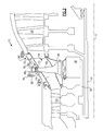
- FIG. 1 schematically illustrates a gas turbine engine 20.
- the gas turbine engine 20 is disclosed herein as a two-spool turbofan that generally incorporates a fan section 22, a compressor section 24, a combustor section 26 and a turbine section 28.
- Alternative engines might include an augmentor section (not shown) among other systems or features.
- the fan section 22 drives air along a bypass flowpath while the compressor section 24 drives air along a core flowpath for compression and communication into the combustor section 26 then expansion through the turbine section 28.
- FIG. 1 schematically illustrates a gas turbine engine 20.
- the gas turbine engine 20 is disclosed herein as a two-spool turbofan that generally incorporates a fan section 22, a compressor section 24, a combustor section 26 and a turbine section 28.
- Alternative engines might include an augmentor section (not shown) among other systems or features.
- the fan section 22 drives air along a bypass flowpath while the compressor section 24 drives air along a core flowpath for compression and communication into the combustor section 26
- the engine 20 generally includes a low speed spool 30 and a high speed spool 32 mounted for rotation about an engine central longitudinal axis A relative to an engine static structure 36 via several bearing systems 38. It should be understood that various bearing systems 38 at various locations may alternatively or additionally be provided.
- the low speed spool 30 generally includes an inner shaft 40 that interconnects a fan 42, a low pressure compressor 44 and a low pressure turbine 46.
- the inner shaft 40 is connected to the fan 42 through a geared architecture 48 to drive the fan 42 at a lower speed than the low speed spool 30.
- the high speed spool 32 includes an outer shaft 50 that interconnects a high pressure compressor 52 and high pressure turbine 54.
- a combustor 56 is arranged between the high pressure compressor 52 and the high pressure turbine 54.
- the inner shaft 40 and the outer shaft 50 are concentric and rotate about the engine central longitudinal axis A which is collinear with their longitudinal axes.
- the core airflow is compressed by the low pressure compressor 44 then the high pressure compressor 52, mixed and burned with fuel in the combustor 56, then expanded over the high pressure turbine 54 and low pressure turbine 46.
- the turbines 54, 46 rotationally drive the respective low speed spool 30 and high speed spool 32 in response to the expansion.
- the turbine section 28 generally includes static structure 36T which is disclosed herein as a mid-turbine case of the gas turbine engine 20.
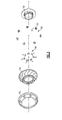
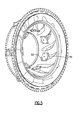
- the mid-turbine case static structure includes an annular inner turbine exhaust case 60, an annular outer turbine exhaust case 62, a vane structure 64, a multiple of tie rods 66 and a respective multiple of tie rod nuts 68 (also shown in Figure 3 ).
- the annular inner turbine exhaust case 62 typically supports a bearing system 38 as well as other components such as seal cartridge structures within which the inner and outer shafts 40, 50 rotate.
- Each of the tie rods 66 are fastened to the annular inner turbine exhaust case 60 through a multiple of fasteners 70 such that the annular outer turbine exhaust case 62 is spaced relative thereto.
- Each of the tie rods 66 are fastened to the annular outer turbine exhaust case 62 by the respective tie rod nut 68 which is threaded via an inner diameter thread 72 to an outer diameter thread 74 of an end section 76 of each tie rod 66.
- Each tie rod nut 68 is then secured to the annular outer turbine exhaust case 62 with one or more fasteners 78 which extend thru "phone dial" holes 80 in the tie rod nut 68. That is, the multiple of holes 80 are arrayed in a circle within a flange 81 of each tie rod nut 68.
- the tie rod nut 68 is threaded to the end section 76 to a predefined torque, such that at least one of the "phone dial" holes 80 become aligned with respective apertures 82 in the annular outer turbine exhaust case 62 into which fasteners 78 (two shown in Figure 2 ) are received to lock the tie rod nut 68 into position.
- the vane structure 64 is located within the annular outer turbine exhaust case 62 ( Figure 4 ). Each of the multiple of tie rods 66 are then inserted into a multiple of vanes 88 of the vane structure 64 ( Figure 5 ). It should be appreciated that each vane 88 of the disclosed multiple need not include a tie rod 66. It should also be appreciated that the vane structure 64 may be manufactured of a multiple of sections or a single integral component which minimizes flow path leakage.
- the annular inner turbine exhaust case 60 is then inserted into the vane structure 64 and the multiple of tie rods 66 are secured thereto by the fasteners 70 ( Figure 7 ) which may be inserted from an inner diameter of the annular inner turbine exhaust case 60.
- the tie rod nut 68 is then threaded to the end section 76 of each of the multiple of tie rods 66 to the predefined torque to center the annular inner turbine exhaust case 60 therein along axis A ( Figure 8 ).
- the "phone dial" holes 80 are aligned with the respective apertures 82 in the annular outer turbine exhaust case 62 to receive the fasteners 78 and thereby lock the tie rod nut 68 into position.
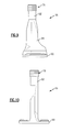
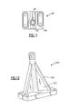
- each tie rod 66 generally includes a base 90, a hollow rod 92 which extends therefrom to the threaded end section 76 and at least one gusset 94 which extends between the base 90 and the hollow rod 92 ( Figures 10 and 11 ).
- the hollow rod 92 may provide a secondary cooling air flow path therethrough.
- the tie rod 66 may be manufactured of a high temperature alloy such as Inco 718.
- the gusset 94 may be generally triangular in shape to facilitate insertion into a respective vane 88 in the assembly method described above. That is, the gusset 94 is aligned generally fore and aft along the engine axis A with respect to the airfoil shaped vane 88. The gusset 94 further facilitates relatively smaller fairings to minimize resistance to the flow of the hot core exhaust gases through the turbine section yet minimize bending and dishing of the annular inner turbine exhaust case 60.
- the tie rod 66A includes a gusset 94 with a beam 100 and a web 102.
- a large axial pressure load typically exists across the mid-turbine case due to higher pressure upstream in the high pressure turbine 54 (HPT) versus the lower pressures downstream in the low pressure turbine 46 (LPT).
- the gussets 94 provide a truss like structure that more effectively resists this load (and reduces axial deflection) than conventional radial spoke like rods. Reductions in the axial deflection of the annular inner turbine exhaust case 60 limits seal excursions and better centers bearing rolling elements on their races of the bearing system 38.
- the tie rods 66 are removable to also accommodate a one piece flowpath vane structure 64 which provides for a reduced gaspath leakage and improved efficiency.
- the tie rods 66 also resist out-of-plane bearing loads such as a blade-out unbalance condition, though the other forces may also apply which, for example, may be present if the engine architecture does not allow a bearing to be centered in the plane of the tie rod 66 or if the tie rod 66 straddles a bearing compartment that contains multiple bearing systems 38.
Landscapes
- Engineering & Computer Science (AREA)
- Mechanical Engineering (AREA)
- General Engineering & Computer Science (AREA)
- Turbine Rotor Nozzle Sealing (AREA)
Applications Claiming Priority (1)
| Application Number | Priority Date | Filing Date | Title |
|---|---|---|---|
| US13/220,640 US9896966B2 (en) | 2011-08-29 | 2011-08-29 | Tie rod for a gas turbine engine |
Publications (3)
| Publication Number | Publication Date |
|---|---|
| EP2565395A2 true EP2565395A2 (fr) | 2013-03-06 |
| EP2565395A3 EP2565395A3 (fr) | 2014-09-17 |
| EP2565395B1 EP2565395B1 (fr) | 2017-10-04 |
Family
ID=46750242
Family Applications (1)
| Application Number | Title | Priority Date | Filing Date |
|---|---|---|---|
| EP12182030.2A Active EP2565395B1 (fr) | 2011-08-29 | 2012-08-28 | Barre d'accouplement pour moteur à turbine à gaz |
Country Status (2)
| Country | Link |
|---|---|
| US (1) | US9896966B2 (fr) |
| EP (1) | EP2565395B1 (fr) |
Cited By (5)
| Publication number | Priority date | Publication date | Assignee | Title |
|---|---|---|---|---|
| EP3045671A1 (fr) * | 2015-01-16 | 2016-07-20 | United Technologies Corporation | Passages de refroidissement pour un cadre de turbine intermédiaire |
| EP3045665A1 (fr) * | 2015-01-09 | 2016-07-20 | United Technologies Corporation | Ensemble de cadre de turbine intermédiaire avec jambe de force pour un moteur à turbine à gaz |
| EP3054101A1 (fr) * | 2015-02-09 | 2016-08-10 | United Technologies Corporation | Passages de refroidissement pour un cadre de turbine intermédiaire |
| EP3070273A1 (fr) * | 2015-03-20 | 2016-09-21 | United Technologies Corporation | Passages de refroidissement pour un cadre de turbine intermédiaire d'un moteur à turbine à gaz |
| EP3030753A4 (fr) * | 2013-08-07 | 2017-04-19 | United Technologies Corporation | Géométrie de plaque de joint d'étanchéité arrière de moteur à turbine à gaz |
Families Citing this family (17)
| Publication number | Priority date | Publication date | Assignee | Title |
|---|---|---|---|---|
| US20140003920A1 (en) * | 2012-07-02 | 2014-01-02 | United Technologies Corporation | Flow metering anti-rotation outer diameter (od) hex nut |
| US9217371B2 (en) | 2012-07-13 | 2015-12-22 | United Technologies Corporation | Mid-turbine frame with tensioned spokes |
| US9222413B2 (en) | 2012-07-13 | 2015-12-29 | United Technologies Corporation | Mid-turbine frame with threaded spokes |
| US9945411B2 (en) * | 2012-08-31 | 2018-04-17 | United Technologies Corporation | Self-anti-rotating dual lock washer |
| US9631517B2 (en) | 2012-12-29 | 2017-04-25 | United Technologies Corporation | Multi-piece fairing for monolithic turbine exhaust case |
| EP3111057B1 (fr) * | 2014-02-26 | 2020-05-06 | United Technologies Corporation | Raccordement de barre d'accouplement pour un cadre de turbine intermédiaire |
| EP3169878A1 (fr) * | 2014-07-18 | 2017-05-24 | Siemens Energy, Inc. | Ensemble turbine pourvu d'entretoises amovibles |
| US20160186614A1 (en) * | 2014-08-27 | 2016-06-30 | United Technologies Corporation | Turbine exhaust case assembly |
| US10309308B2 (en) * | 2015-01-16 | 2019-06-04 | United Technologies Corporation | Cooling passages for a mid-turbine frame |
| US10392974B2 (en) | 2015-02-03 | 2019-08-27 | United Technologies Corporation | Mid-turbine frame assembly |
| US9732628B2 (en) * | 2015-03-20 | 2017-08-15 | United Technologies Corporation | Cooling passages for a mid-turbine frame |
| US10443449B2 (en) | 2015-07-24 | 2019-10-15 | Pratt & Whitney Canada Corp. | Spoke mounting arrangement |
| US10247035B2 (en) | 2015-07-24 | 2019-04-02 | Pratt & Whitney Canada Corp. | Spoke locking architecture |
| CN107849937B (zh) | 2015-07-24 | 2020-06-19 | 普拉特-惠特尼加拿大公司 | 涡轮中间框架辐条冷却系统及方法 |
| US10815830B2 (en) * | 2017-12-21 | 2020-10-27 | Raytheon Technologies Corporation | Lightweight tierod |
| US10941669B2 (en) * | 2018-12-21 | 2021-03-09 | Raytheon Technologies Corporation | Diffuser case support structure |
| GB202018430D0 (en) * | 2020-11-24 | 2021-01-06 | Rolls Royce Plc | Support assembly for gas turbine engine |
Family Cites Families (46)
| Publication number | Priority date | Publication date | Assignee | Title |
|---|---|---|---|---|
| US529222A (en) | 1894-11-13 | Vending-machine | ||
| US3722215A (en) * | 1971-03-30 | 1973-03-27 | A Polyakov | Gas-turbine plant |
| US4086946A (en) * | 1976-05-07 | 1978-05-02 | Taper Line, Incorporated | Locking nut |
| US4965994A (en) | 1988-12-16 | 1990-10-30 | General Electric Company | Jet engine turbine support |
| DE4015207C1 (en) | 1990-05-11 | 1991-10-17 | Mtu Muenchen Gmbh | Bearing for aircraft engine rotor blade - incorporates torsional tie rod in compact design |
| US5452575A (en) | 1993-09-07 | 1995-09-26 | General Electric Company | Aircraft gas turbine engine thrust mount |
| US5443229A (en) | 1993-12-13 | 1995-08-22 | General Electric Company | Aircraft gas turbine engine sideways mount |
| FR2746828B1 (fr) | 1996-04-02 | 1998-08-14 | Spit Soc Prospect Inv Techn | Connecteur d'ancrage d'une dalle en beton sur un support metallique |
| US6000906A (en) * | 1997-09-12 | 1999-12-14 | Alliedsignal Inc. | Ceramic airfoil |
| JP2001259784A (ja) | 2000-03-21 | 2001-09-25 | Showa Corp | 中空タイロッドの製造方法 |
| US20020195793A1 (en) * | 2001-06-25 | 2002-12-26 | Roger Gangwer | Trailer for a trike constructed from a motorcycle |
| US6708482B2 (en) | 2001-11-29 | 2004-03-23 | General Electric Company | Aircraft engine with inter-turbine engine frame |
| JP4044483B2 (ja) * | 2003-04-25 | 2008-02-06 | 新日本製鐵株式会社 | ガセットプレートを用いた構造物の接合構造および建築物 |
| US7409819B2 (en) | 2004-10-29 | 2008-08-12 | General Electric Company | Gas turbine engine and method of assembling same |
| US7326030B2 (en) | 2005-02-02 | 2008-02-05 | Siemens Power Generation, Inc. | Support system for a composite airfoil in a turbine engine |
| US7603844B2 (en) | 2005-10-19 | 2009-10-20 | General Electric Company | Gas turbine engine assembly and methods of assembling same |
| US7493753B2 (en) | 2005-10-19 | 2009-02-24 | General Electric Company | Gas turbine engine assembly and methods of assembling same |
| US7490461B2 (en) | 2005-10-19 | 2009-02-17 | General Electric Company | Gas turbine engine assembly and methods of assembling same |
| US7726113B2 (en) | 2005-10-19 | 2010-06-01 | General Electric Company | Gas turbine engine assembly and methods of assembling same |
| US7685808B2 (en) | 2005-10-19 | 2010-03-30 | General Electric Company | Gas turbine engine assembly and methods of assembling same |
| US7490460B2 (en) | 2005-10-19 | 2009-02-17 | General Electric Company | Gas turbine engine assembly and methods of assembling same |
| US7493754B2 (en) | 2005-10-19 | 2009-02-24 | General Electric Company | Gas turbine engine assembly and methods of assembling same |
| US7752836B2 (en) | 2005-10-19 | 2010-07-13 | General Electric Company | Gas turbine assembly and methods of assembling same |
| US7513103B2 (en) | 2005-10-19 | 2009-04-07 | General Electric Company | Gas turbine engine assembly and methods of assembling same |
| US7526913B2 (en) | 2005-10-19 | 2009-05-05 | General Electric Company | Gas turbine engine assembly and methods of assembling same |
| US7579087B2 (en) | 2006-01-10 | 2009-08-25 | United Technologies Corporation | Thermal barrier coating compositions, processes for applying same and articles coated with same |
| US7677047B2 (en) | 2006-03-29 | 2010-03-16 | United Technologies Corporation | Inverted stiffened shell panel torque transmission for loaded struts and mid-turbine frames |
| US7775049B2 (en) | 2006-04-04 | 2010-08-17 | United Technologies Corporation | Integrated strut design for mid-turbine frames with U-base |
| US7610763B2 (en) | 2006-05-09 | 2009-11-03 | United Technologies Corporation | Tailorable design configuration topologies for aircraft engine mid-turbine frames |
| US7380561B2 (en) | 2006-07-18 | 2008-06-03 | Nobert David T | Portable, displaceable anchor stand |
| US7594404B2 (en) | 2006-07-27 | 2009-09-29 | United Technologies Corporation | Embedded mount for mid-turbine frame |
| US7594405B2 (en) | 2006-07-27 | 2009-09-29 | United Technologies Corporation | Catenary mid-turbine frame design |
| US7632064B2 (en) | 2006-09-01 | 2009-12-15 | United Technologies Corporation | Variable geometry guide vane for a gas turbine engine |
| US7815417B2 (en) | 2006-09-01 | 2010-10-19 | United Technologies Corporation | Guide vane for a gas turbine engine |
| US7926259B2 (en) | 2006-10-31 | 2011-04-19 | General Electric Company | Turbofan engine assembly and method of assembling same |
| US7921634B2 (en) | 2006-10-31 | 2011-04-12 | General Electric Company | Turbofan engine assembly and method of assembling same |
| US7905083B2 (en) | 2006-10-31 | 2011-03-15 | General Electric Company | Turbofan engine assembly and method of assembling same |
| US7841165B2 (en) | 2006-10-31 | 2010-11-30 | General Electric Company | Gas turbine engine assembly and methods of assembling same |
| US7882693B2 (en) | 2006-11-29 | 2011-02-08 | General Electric Company | Turbofan engine assembly and method of assembling same |
| US7797946B2 (en) | 2006-12-06 | 2010-09-21 | United Technologies Corporation | Double U design for mid-turbine frame struts |
| US7762087B2 (en) | 2006-12-06 | 2010-07-27 | United Technologies Corporation | Rotatable integrated segmented mid-turbine frames |
| US8215901B2 (en) * | 2007-12-03 | 2012-07-10 | United Technologies Corporation | Gas turbine engines and related systems involving offset turbine frame struts |
| US8061969B2 (en) | 2008-11-28 | 2011-11-22 | Pratt & Whitney Canada Corp. | Mid turbine frame system for gas turbine engine |
| KR100995908B1 (ko) | 2009-12-18 | 2010-11-22 | 주식회사 엘씨엘 | 연결 장치가 설치된 도로 시설물 |
| US8371249B1 (en) * | 2011-06-14 | 2013-02-12 | Cole Little | Spring loaded dog toy |
| US8770924B2 (en) * | 2011-07-07 | 2014-07-08 | Siemens Energy, Inc. | Gas turbine engine with angled and radial supports |
-
2011
- 2011-08-29 US US13/220,640 patent/US9896966B2/en active Active
-
2012
- 2012-08-28 EP EP12182030.2A patent/EP2565395B1/fr active Active
Non-Patent Citations (1)
| Title |
|---|
| None |
Cited By (10)
| Publication number | Priority date | Publication date | Assignee | Title |
|---|---|---|---|---|
| EP3030753A4 (fr) * | 2013-08-07 | 2017-04-19 | United Technologies Corporation | Géométrie de plaque de joint d'étanchéité arrière de moteur à turbine à gaz |
| US10329936B2 (en) | 2013-08-07 | 2019-06-25 | United Technologies Corporation | Gas turbine engine aft seal plate geometry |
| US10890080B2 (en) | 2013-08-07 | 2021-01-12 | Raytheon Technologies Corporation | Gas turbine engine aft seal plate geometry |
| EP3045665A1 (fr) * | 2015-01-09 | 2016-07-20 | United Technologies Corporation | Ensemble de cadre de turbine intermédiaire avec jambe de force pour un moteur à turbine à gaz |
| EP3045671A1 (fr) * | 2015-01-16 | 2016-07-20 | United Technologies Corporation | Passages de refroidissement pour un cadre de turbine intermédiaire |
| US9915171B2 (en) | 2015-01-16 | 2018-03-13 | United Technologies Corporation | Cooling passages for a mid-turbine frame |
| EP3054101A1 (fr) * | 2015-02-09 | 2016-08-10 | United Technologies Corporation | Passages de refroidissement pour un cadre de turbine intermédiaire |
| US9803502B2 (en) | 2015-02-09 | 2017-10-31 | United Technologies Corporation | Cooling passages for a mid-turbine frame |
| EP3070273A1 (fr) * | 2015-03-20 | 2016-09-21 | United Technologies Corporation | Passages de refroidissement pour un cadre de turbine intermédiaire d'un moteur à turbine à gaz |
| US9915170B2 (en) | 2015-03-20 | 2018-03-13 | United Technologies Corporation | Cooling passages for a mid-turbine frame |
Also Published As
| Publication number | Publication date |
|---|---|
| EP2565395B1 (fr) | 2017-10-04 |
| US20130052006A1 (en) | 2013-02-28 |
| EP2565395A3 (fr) | 2014-09-17 |
| US9896966B2 (en) | 2018-02-20 |
Similar Documents
| Publication | Publication Date | Title |
|---|---|---|
| EP2565395B1 (fr) | Barre d'accouplement pour moteur à turbine à gaz | |
| US10753279B2 (en) | Gas turbine engine mid turbine frame bearing support | |
| US9200536B2 (en) | Mid turbine frame (MTF) for a gas turbine engine | |
| US9587514B2 (en) | Vane insertable tie rods with keyed connections | |
| US9222413B2 (en) | Mid-turbine frame with threaded spokes | |
| US10060291B2 (en) | Mid-turbine frame rod and turbine case flange | |
| EP2901082B1 (fr) | Bras de carter de diffuseur intérieur pour chambre de combustion d'un moteur à turbine à gaz | |
| US10184402B2 (en) | Ceramic matrix composite turbine exhaust case for a gas turbine engine | |
| US9328629B2 (en) | Outer case with gusseted boss | |
| US9879558B2 (en) | Low leakage multi-directional interface for a gas turbine engine | |
| US20130309078A1 (en) | Shield system for gas turbine engine | |
| EP3048259A1 (fr) | Ensemble de cadre de turbine intermédiaire avec jambes de force pour un moteur à turbine à gaz | |
| US20200011185A1 (en) | Turbine Engine and Method of Assembling | |
| EP2855892A2 (fr) | Portée de joint d'étanchéité pour structure statique d'un moteur à turbine à gaz | |
| EP3246517A1 (fr) | Ouvertures de fixation pour distribution de contrainte | |
| EP3263841B1 (fr) | Bossage de carter de turbine | |
| EP3047110B1 (fr) | Premier support d'aube à division de flux pour moteur à turbine à gaz et procédé d'écoulement de fluide à travers un moteur à turbine à gaz. | |
| US11199104B2 (en) | Seal anti-rotation | |
| US20150377073A1 (en) | Titanium aluminide turbine exhaust structure | |
| EP3011155B1 (fr) | Bouclier thermique |
Legal Events
| Date | Code | Title | Description |
|---|---|---|---|
| PUAI | Public reference made under article 153(3) epc to a published international application that has entered the european phase |
Free format text: ORIGINAL CODE: 0009012 |
|
| AK | Designated contracting states |
Kind code of ref document: A2 Designated state(s): AL AT BE BG CH CY CZ DE DK EE ES FI FR GB GR HR HU IE IS IT LI LT LU LV MC MK MT NL NO PL PT RO RS SE SI SK SM TR |
|
| AX | Request for extension of the european patent |
Extension state: BA ME |
|
| PUAL | Search report despatched |
Free format text: ORIGINAL CODE: 0009013 |
|
| AK | Designated contracting states |
Kind code of ref document: A3 Designated state(s): AL AT BE BG CH CY CZ DE DK EE ES FI FR GB GR HR HU IE IS IT LI LT LU LV MC MK MT NL NO PL PT RO RS SE SI SK SM TR |
|
| AX | Request for extension of the european patent |
Extension state: BA ME |
|
| RIC1 | Information provided on ipc code assigned before grant |
Ipc: F01D 25/24 20060101ALI20140811BHEP Ipc: F01D 25/28 20060101ALI20140811BHEP Ipc: F01D 25/16 20060101AFI20140811BHEP |
|
| 17P | Request for examination filed |
Effective date: 20150317 |
|
| RBV | Designated contracting states (corrected) |
Designated state(s): AL AT BE BG CH CY CZ DE DK EE ES FI FR GB GR HR HU IE IS IT LI LT LU LV MC MK MT NL NO PL PT RO RS SE SI SK SM TR |
|
| 17Q | First examination report despatched |
Effective date: 20160511 |
|
| RAP1 | Party data changed (applicant data changed or rights of an application transferred) |
Owner name: UNITED TECHNOLOGIES CORPORATION |
|
| STAA | Information on the status of an ep patent application or granted ep patent |
Free format text: STATUS: EXAMINATION IS IN PROGRESS |
|
| GRAP | Despatch of communication of intention to grant a patent |
Free format text: ORIGINAL CODE: EPIDOSNIGR1 |
|
| STAA | Information on the status of an ep patent application or granted ep patent |
Free format text: STATUS: GRANT OF PATENT IS INTENDED |
|
| INTG | Intention to grant announced |
Effective date: 20170329 |
|
| GRAS | Grant fee paid |
Free format text: ORIGINAL CODE: EPIDOSNIGR3 |
|
| GRAA | (expected) grant |
Free format text: ORIGINAL CODE: 0009210 |
|
| STAA | Information on the status of an ep patent application or granted ep patent |
Free format text: STATUS: THE PATENT HAS BEEN GRANTED |
|
| AK | Designated contracting states |
Kind code of ref document: B1 Designated state(s): AL AT BE BG CH CY CZ DE DK EE ES FI FR GB GR HR HU IE IS IT LI LT LU LV MC MK MT NL NO PL PT RO RS SE SI SK SM TR |
|
| REG | Reference to a national code |
Ref country code: GB Ref legal event code: FG4D |
|
| REG | Reference to a national code |
Ref country code: CH Ref legal event code: EP |
|
| REG | Reference to a national code |
Ref country code: AT Ref legal event code: REF Ref document number: 934258 Country of ref document: AT Kind code of ref document: T Effective date: 20171015 |
|
| REG | Reference to a national code |
Ref country code: IE Ref legal event code: FG4D |
|
| REG | Reference to a national code |
Ref country code: DE Ref legal event code: R096 Ref document number: 602012038062 Country of ref document: DE |
|
| REG | Reference to a national code |
Ref country code: NL Ref legal event code: MP Effective date: 20171004 |
|
| REG | Reference to a national code |
Ref country code: LT Ref legal event code: MG4D |
|
| REG | Reference to a national code |
Ref country code: AT Ref legal event code: MK05 Ref document number: 934258 Country of ref document: AT Kind code of ref document: T Effective date: 20171004 |
|
| PG25 | Lapsed in a contracting state [announced via postgrant information from national office to epo] |
Ref country code: NL Free format text: LAPSE BECAUSE OF FAILURE TO SUBMIT A TRANSLATION OF THE DESCRIPTION OR TO PAY THE FEE WITHIN THE PRESCRIBED TIME-LIMIT Effective date: 20171004 |
|
| PG25 | Lapsed in a contracting state [announced via postgrant information from national office to epo] |
Ref country code: LT Free format text: LAPSE BECAUSE OF FAILURE TO SUBMIT A TRANSLATION OF THE DESCRIPTION OR TO PAY THE FEE WITHIN THE PRESCRIBED TIME-LIMIT Effective date: 20171004 Ref country code: NO Free format text: LAPSE BECAUSE OF FAILURE TO SUBMIT A TRANSLATION OF THE DESCRIPTION OR TO PAY THE FEE WITHIN THE PRESCRIBED TIME-LIMIT Effective date: 20180104 Ref country code: FI Free format text: LAPSE BECAUSE OF FAILURE TO SUBMIT A TRANSLATION OF THE DESCRIPTION OR TO PAY THE FEE WITHIN THE PRESCRIBED TIME-LIMIT Effective date: 20171004 Ref country code: SE Free format text: LAPSE BECAUSE OF FAILURE TO SUBMIT A TRANSLATION OF THE DESCRIPTION OR TO PAY THE FEE WITHIN THE PRESCRIBED TIME-LIMIT Effective date: 20171004 Ref country code: ES Free format text: LAPSE BECAUSE OF FAILURE TO SUBMIT A TRANSLATION OF THE DESCRIPTION OR TO PAY THE FEE WITHIN THE PRESCRIBED TIME-LIMIT Effective date: 20171004 |
|
| PG25 | Lapsed in a contracting state [announced via postgrant information from national office to epo] |
Ref country code: IS Free format text: LAPSE BECAUSE OF FAILURE TO SUBMIT A TRANSLATION OF THE DESCRIPTION OR TO PAY THE FEE WITHIN THE PRESCRIBED TIME-LIMIT Effective date: 20180204 Ref country code: BG Free format text: LAPSE BECAUSE OF FAILURE TO SUBMIT A TRANSLATION OF THE DESCRIPTION OR TO PAY THE FEE WITHIN THE PRESCRIBED TIME-LIMIT Effective date: 20180104 Ref country code: RS Free format text: LAPSE BECAUSE OF FAILURE TO SUBMIT A TRANSLATION OF THE DESCRIPTION OR TO PAY THE FEE WITHIN THE PRESCRIBED TIME-LIMIT Effective date: 20171004 Ref country code: GR Free format text: LAPSE BECAUSE OF FAILURE TO SUBMIT A TRANSLATION OF THE DESCRIPTION OR TO PAY THE FEE WITHIN THE PRESCRIBED TIME-LIMIT Effective date: 20180105 Ref country code: LV Free format text: LAPSE BECAUSE OF FAILURE TO SUBMIT A TRANSLATION OF THE DESCRIPTION OR TO PAY THE FEE WITHIN THE PRESCRIBED TIME-LIMIT Effective date: 20171004 Ref country code: AT Free format text: LAPSE BECAUSE OF FAILURE TO SUBMIT A TRANSLATION OF THE DESCRIPTION OR TO PAY THE FEE WITHIN THE PRESCRIBED TIME-LIMIT Effective date: 20171004 Ref country code: HR Free format text: LAPSE BECAUSE OF FAILURE TO SUBMIT A TRANSLATION OF THE DESCRIPTION OR TO PAY THE FEE WITHIN THE PRESCRIBED TIME-LIMIT Effective date: 20171004 |
|
| REG | Reference to a national code |
Ref country code: DE Ref legal event code: R097 Ref document number: 602012038062 Country of ref document: DE |
|
| PG25 | Lapsed in a contracting state [announced via postgrant information from national office to epo] |
Ref country code: CZ Free format text: LAPSE BECAUSE OF FAILURE TO SUBMIT A TRANSLATION OF THE DESCRIPTION OR TO PAY THE FEE WITHIN THE PRESCRIBED TIME-LIMIT Effective date: 20171004 Ref country code: SK Free format text: LAPSE BECAUSE OF FAILURE TO SUBMIT A TRANSLATION OF THE DESCRIPTION OR TO PAY THE FEE WITHIN THE PRESCRIBED TIME-LIMIT Effective date: 20171004 Ref country code: EE Free format text: LAPSE BECAUSE OF FAILURE TO SUBMIT A TRANSLATION OF THE DESCRIPTION OR TO PAY THE FEE WITHIN THE PRESCRIBED TIME-LIMIT Effective date: 20171004 Ref country code: DK Free format text: LAPSE BECAUSE OF FAILURE TO SUBMIT A TRANSLATION OF THE DESCRIPTION OR TO PAY THE FEE WITHIN THE PRESCRIBED TIME-LIMIT Effective date: 20171004 |
|
| PLBE | No opposition filed within time limit |
Free format text: ORIGINAL CODE: 0009261 |
|
| STAA | Information on the status of an ep patent application or granted ep patent |
Free format text: STATUS: NO OPPOSITION FILED WITHIN TIME LIMIT |
|
| PG25 | Lapsed in a contracting state [announced via postgrant information from national office to epo] |
Ref country code: RO Free format text: LAPSE BECAUSE OF FAILURE TO SUBMIT A TRANSLATION OF THE DESCRIPTION OR TO PAY THE FEE WITHIN THE PRESCRIBED TIME-LIMIT Effective date: 20171004 Ref country code: PL Free format text: LAPSE BECAUSE OF FAILURE TO SUBMIT A TRANSLATION OF THE DESCRIPTION OR TO PAY THE FEE WITHIN THE PRESCRIBED TIME-LIMIT Effective date: 20171004 Ref country code: SM Free format text: LAPSE BECAUSE OF FAILURE TO SUBMIT A TRANSLATION OF THE DESCRIPTION OR TO PAY THE FEE WITHIN THE PRESCRIBED TIME-LIMIT Effective date: 20171004 Ref country code: IT Free format text: LAPSE BECAUSE OF FAILURE TO SUBMIT A TRANSLATION OF THE DESCRIPTION OR TO PAY THE FEE WITHIN THE PRESCRIBED TIME-LIMIT Effective date: 20171004 |
|
| 26N | No opposition filed |
Effective date: 20180705 |
|
| PG25 | Lapsed in a contracting state [announced via postgrant information from national office to epo] |
Ref country code: SI Free format text: LAPSE BECAUSE OF FAILURE TO SUBMIT A TRANSLATION OF THE DESCRIPTION OR TO PAY THE FEE WITHIN THE PRESCRIBED TIME-LIMIT Effective date: 20171004 |
|
| PG25 | Lapsed in a contracting state [announced via postgrant information from national office to epo] |
Ref country code: MC Free format text: LAPSE BECAUSE OF FAILURE TO SUBMIT A TRANSLATION OF THE DESCRIPTION OR TO PAY THE FEE WITHIN THE PRESCRIBED TIME-LIMIT Effective date: 20171004 |
|
| REG | Reference to a national code |
Ref country code: CH Ref legal event code: PL |
|
| PG25 | Lapsed in a contracting state [announced via postgrant information from national office to epo] |
Ref country code: CH Free format text: LAPSE BECAUSE OF NON-PAYMENT OF DUE FEES Effective date: 20180831 Ref country code: LI Free format text: LAPSE BECAUSE OF NON-PAYMENT OF DUE FEES Effective date: 20180831 Ref country code: LU Free format text: LAPSE BECAUSE OF NON-PAYMENT OF DUE FEES Effective date: 20180828 |
|
| REG | Reference to a national code |
Ref country code: BE Ref legal event code: MM Effective date: 20180831 |
|
| PG25 | Lapsed in a contracting state [announced via postgrant information from national office to epo] |
Ref country code: FR Free format text: LAPSE BECAUSE OF NON-PAYMENT OF DUE FEES Effective date: 20180831 Ref country code: BE Free format text: LAPSE BECAUSE OF NON-PAYMENT OF DUE FEES Effective date: 20180831 |
|
| PG25 | Lapsed in a contracting state [announced via postgrant information from national office to epo] |
Ref country code: MT Free format text: LAPSE BECAUSE OF NON-PAYMENT OF DUE FEES Effective date: 20180828 |
|
| PG25 | Lapsed in a contracting state [announced via postgrant information from national office to epo] |
Ref country code: TR Free format text: LAPSE BECAUSE OF FAILURE TO SUBMIT A TRANSLATION OF THE DESCRIPTION OR TO PAY THE FEE WITHIN THE PRESCRIBED TIME-LIMIT Effective date: 20171004 |
|
| PG25 | Lapsed in a contracting state [announced via postgrant information from national office to epo] |
Ref country code: HU Free format text: LAPSE BECAUSE OF FAILURE TO SUBMIT A TRANSLATION OF THE DESCRIPTION OR TO PAY THE FEE WITHIN THE PRESCRIBED TIME-LIMIT; INVALID AB INITIO Effective date: 20120828 Ref country code: PT Free format text: LAPSE BECAUSE OF FAILURE TO SUBMIT A TRANSLATION OF THE DESCRIPTION OR TO PAY THE FEE WITHIN THE PRESCRIBED TIME-LIMIT Effective date: 20171004 |
|
| PG25 | Lapsed in a contracting state [announced via postgrant information from national office to epo] |
Ref country code: CY Free format text: LAPSE BECAUSE OF FAILURE TO SUBMIT A TRANSLATION OF THE DESCRIPTION OR TO PAY THE FEE WITHIN THE PRESCRIBED TIME-LIMIT Effective date: 20171004 Ref country code: IE Free format text: LAPSE BECAUSE OF NON-PAYMENT OF DUE FEES Effective date: 20180828 Ref country code: MK Free format text: LAPSE BECAUSE OF NON-PAYMENT OF DUE FEES Effective date: 20171004 |
|
| PG25 | Lapsed in a contracting state [announced via postgrant information from national office to epo] |
Ref country code: AL Free format text: LAPSE BECAUSE OF FAILURE TO SUBMIT A TRANSLATION OF THE DESCRIPTION OR TO PAY THE FEE WITHIN THE PRESCRIBED TIME-LIMIT Effective date: 20171004 |
|
| REG | Reference to a national code |
Ref country code: DE Ref legal event code: R081 Ref document number: 602012038062 Country of ref document: DE Owner name: RAYTHEON TECHNOLOGIES CORPORATION (N.D.GES.D.S, US Free format text: FORMER OWNER: UNITED TECHNOLOGIES CORPORATION, FARMINGTON, CONN., US |
|
| P01 | Opt-out of the competence of the unified patent court (upc) registered |
Effective date: 20230520 |
|
| PGFP | Annual fee paid to national office [announced via postgrant information from national office to epo] |
Ref country code: GB Payment date: 20230720 Year of fee payment: 12 |
|
| PGFP | Annual fee paid to national office [announced via postgrant information from national office to epo] |
Ref country code: DE Payment date: 20230720 Year of fee payment: 12 |