EP2565384B1 - Beschaufelter Rotor und zugehöriges Montageverfahren - Google Patents
Beschaufelter Rotor und zugehöriges Montageverfahren Download PDFInfo
- Publication number
- EP2565384B1 EP2565384B1 EP12182029.4A EP12182029A EP2565384B1 EP 2565384 B1 EP2565384 B1 EP 2565384B1 EP 12182029 A EP12182029 A EP 12182029A EP 2565384 B1 EP2565384 B1 EP 2565384B1
- Authority
- EP
- European Patent Office
- Prior art keywords
- blade
- rotor
- slots
- recited
- lock
- Prior art date
- Legal status (The legal status is an assumption and is not a legal conclusion. Google has not performed a legal analysis and makes no representation as to the accuracy of the status listed.)
- Active
Links
- 238000000034 method Methods 0.000 title claims description 5
- 238000009434 installation Methods 0.000 description 5
- 230000000295 complement effect Effects 0.000 description 2
- 230000014759 maintenance of location Effects 0.000 description 2
- 229910000838 Al alloy Inorganic materials 0.000 description 1
- 229910001069 Ti alloy Inorganic materials 0.000 description 1
- 239000002131 composite material Substances 0.000 description 1
- 230000006835 compression Effects 0.000 description 1
- 238000007906 compression Methods 0.000 description 1
- 239000000446 fuel Substances 0.000 description 1
- 239000000463 material Substances 0.000 description 1
- 238000012986 modification Methods 0.000 description 1
- 230000004048 modification Effects 0.000 description 1
- 230000002093 peripheral effect Effects 0.000 description 1
- 230000003068 static effect Effects 0.000 description 1
Images


Classifications
-
- F—MECHANICAL ENGINEERING; LIGHTING; HEATING; WEAPONS; BLASTING
- F01—MACHINES OR ENGINES IN GENERAL; ENGINE PLANTS IN GENERAL; STEAM ENGINES
- F01D—NON-POSITIVE DISPLACEMENT MACHINES OR ENGINES, e.g. STEAM TURBINES
- F01D5/00—Blades; Blade-carrying members; Heating, heat-insulating, cooling or antivibration means on the blades or the members
- F01D5/30—Fixing blades to rotors; Blade roots ; Blade spacers
- F01D5/32—Locking, e.g. by final locking blades or keys
- F01D5/326—Locking of axial insertion type blades by other means
-
- Y—GENERAL TAGGING OF NEW TECHNOLOGICAL DEVELOPMENTS; GENERAL TAGGING OF CROSS-SECTIONAL TECHNOLOGIES SPANNING OVER SEVERAL SECTIONS OF THE IPC; TECHNICAL SUBJECTS COVERED BY FORMER USPC CROSS-REFERENCE ART COLLECTIONS [XRACs] AND DIGESTS
- Y02—TECHNOLOGIES OR APPLICATIONS FOR MITIGATION OR ADAPTATION AGAINST CLIMATE CHANGE
- Y02T—CLIMATE CHANGE MITIGATION TECHNOLOGIES RELATED TO TRANSPORTATION
- Y02T50/00—Aeronautics or air transport
- Y02T50/60—Efficient propulsion technologies, e.g. for aircraft
-
- Y—GENERAL TAGGING OF NEW TECHNOLOGICAL DEVELOPMENTS; GENERAL TAGGING OF CROSS-SECTIONAL TECHNOLOGIES SPANNING OVER SEVERAL SECTIONS OF THE IPC; TECHNICAL SUBJECTS COVERED BY FORMER USPC CROSS-REFERENCE ART COLLECTIONS [XRACs] AND DIGESTS
- Y10—TECHNICAL SUBJECTS COVERED BY FORMER USPC
- Y10T—TECHNICAL SUBJECTS COVERED BY FORMER US CLASSIFICATION
- Y10T29/00—Metal working
- Y10T29/49—Method of mechanical manufacture
- Y10T29/49316—Impeller making
Definitions
- the present disclosure relates to an axial retention system for a bladed rotor, particularly a fan rotor of a gas turbine engine.
- a fan rotor of the type used in an aircraft gas turbine engine includes a hub which rotates about a rotational axis and an array of blades which extend radially from the hub.
- the hub includes a series of circumferentially distributed peripheral slots. Each slot extends in a predominantly axial direction. Each slot is typically open at either a forward section of the hub, an aft section of the hub, or both to facilitate axial installation and removal of the blades.
- An axial retention system prevents the installed blades from migrating axially out of the slots.
- a bladed rotor having the features of the preamble of claim 1 is disclosed in FR-A-2524933 .
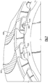
- FIG. 1 schematically illustrates a gas turbine engine 20.
- the gas turbine engine 20 is disclosed herein as a turbofan that generally incorporates a fan section 22, a compressor section 24, a combustor section 26 and a turbine section 28.
- Alternative engines might include an augmentor section (not shown) among other systems or features.
- the fan section 22 drives air along a bypass flowpath while the compressor section 24 drives air along a core flowpath for compression and communication into the combustor section 26 then expansion through the turbine section 28.
- the engine 20 generally includes a low speed spool 30 and a high speed spool 32 mounted for rotation about an engine central longitudinal axis A relative to an engine static structure 36 via several bearing systems 38. It should be understood that various bearing systems 38 at various locations may alternatively or additionally be provided.
- the low speed spool 30 generally includes an inner shaft 40 that interconnects a fan 42, a low pressure compressor 44 and a low pressure turbine 46.
- the inner shaft 40 is connected to the fan 42 through a geared architecture 48 to drive the fan 42 at a lower speed than the low speed spool 30.
- the high speed spool 32 includes an outer shaft 50 that interconnects a high pressure compressor 52 and high pressure turbine 54.
- a combustor 56 is arranged between the high pressure compressor 52 and the high pressure turbine 54.
- the inner shaft 40 and the outer shaft 50 are concentric and rotate about the engine central longitudinal axis A which is collinear with their longitudinal axes.
- the core airflow is compressed by the low pressure compressor 44 then the high pressure compressor 52, mixed and burned with fuel in the combustor 56, then expanded over the high pressure turbine 54 and low pressure turbine 46.
- the turbines 54, 46 rotationally drive the respective low speed spool 30 and high speed spool 32 in response to the expansion.
- the fan 42 includes a plurality of circumferentially spaced fan blades 60 which may be manufactured of a high-strength, low weight material such as an aluminum alloy, titanium alloy, composite, or combinations thereof. It should be understood that although a single fan stage is illustrated and described in the disclosed embodiment, additional stages as well as other bladed rotor with other blades that are received with an axial interface inclusive of fan blades, compressor blades and turbine blades will also benefit herefrom.
- a high-strength, low weight material such as an aluminum alloy, titanium alloy, composite, or combinations thereof.
- Each fan blade 60 generally includes an innermost root portion 62, an intermediate platform portion 64, and an outermost airfoil portion 66.
- the root portion 60 may define an attachment such as an inverted fir-tree, bulb, or dovetail so the fan blade 60 is slidably received in a complementary configured blade slot 68 in a fan rotor hub 70 to provide a bladed rotor 72 about axis A.
- the illustrated blade slots when viewed radially toward the axis A, have a curved profile.
- the slots may be linear slots having a linear centerline oriented parallel or oblique to the rotational axis.
- Each slot 68 includes a forward section 68F and an aft section 68A to accommodate installation and removal of the fan blades 60 in a generally axial direction ( Figure 3 ).
- axial refers not only to a direction strictly parallel to the rotational axis but also to directions somewhat non-parallel to the axis, such as the slotwise direction defined by a curved or linear slot.
- Such bladed rotors sometimes require two or more different blades 60A, 60B mounted to the same rotor hub 70 to facilitate, for example, vibration tuning, flutter margin control and/or adjustment of other parameters. To achieve the desired parameters it is imperative that the specific blade 60A, 60B always be mounted at their proper circumferential positions in a mistake-proof manner.
- the bladed rotor 72 includes a multiple of lock attachments 74 such as annular hooks which support a blade lock 76 such as a snap ring.
- the blade lock 76 is received within the multiple of lock attachments 74 along an aft face 70A of the rotor hub 70 to interface with each blade slot 68.
- the blade lock 76 may be circumferentially continuous except for a split 80 that enables a technician to deflect the blade lock 76 to mount within the multiple of lock attachments 74 as generally known.
- the bladed rotor 72 is described somewhat generically and that additional hub components such as a bayonet ring, a retainer ring and others may also be provided but need not be described in detail herein.
- the blade lock 76 includes at least one interface feature 82 at specific circumferential features with respect to a blade slot 68 to interact with a blade feature 84 and assure that only the desired particular type of blade 60A may be mounted within that associated blade slot 68. That is, the interface feature 82 is circumferentially arranged to align with each blade slot 68 to mount only specific desired blade types such as blade 60A ( Figure 6 ). The remainder of the blade slots 68 will receive, for example, blades 60B.
- the interface feature 82A ( Figure 7 ) and the blade feature 84A are complementary features, namely a slot in the blade lock 76 which receives a key which extends from the root portion 62 of blade 60A.
- the key may be positioned to extend from an aft axial end section 62A of the root portion 62.
- the disclosed interface permits only blade 60A to fit into the appropriate blade slot 68 adjacent to the interface feature 82 and prevents the blade 60B from being mounted into a blade slot 68 which is not adjacent to that interface feature.
- the key will not fit the slot, and the blade 60A cannot be fully installed in the axial direction to thereby prevent installation of a front blade lock (not shown) which would halt installation until all blades 60A, 60B are positioned at their correct locations. A mistake-proof interface is thereby provided.
- the interface feature 82A, 82B and the blade feature 84A, 84B may be independent and mutually exclusive so that only the single proper blade 60A, 60B may be located in the proper blade slot 68 ( Figure 7 ). It should be understood that various geometric shapes such as arcuate, rectilinear, triangular, and others may define the interface features 82A, 82B and the blade features 84A, 84B to facilitate a mistake-proof installation.
Landscapes
- Engineering & Computer Science (AREA)
- Mechanical Engineering (AREA)
- General Engineering & Computer Science (AREA)
- Structures Of Non-Positive Displacement Pumps (AREA)
Claims (12)
- Beschaufelter Rotor (72), umfassend:eine Rotornabe (70), die eine Vielzahl von Schaufelschlitzen (68) definiert;eine Schaufelverriegelung (76), die an die Rotornabe (70) neben der Vielzahl von Schaufelschlitzen (68) montiert ist, wobei die Schaufelverriegelung (76) mindestens ein Schnittstellenmerkmal (82) beinhaltet, das in Umfangsrichtung an einem ersten der Vielzahl von Schaufelschlitzen (68) ausgerichtet ist; undeine erste Rotorschaufel (60A);wobei die erste Rotorschaufel (60A) ein Schaufelmerkmal (84) aufweist, das mit dem Schnittstellenmerkmal (82) koppelt, um zu ermöglichen, dass die erste Rotorschaufel (60A) axial in den ersten der Vielzahl von Schaufelschlitzen (68) montiert wird, jedoch nicht in einen verbleibenden der Vielzahl von Schaufelschlitzen (68); dadurch gekennzeichnet, dass:das Schaufelmerkmal (84) oder jedes der Vielzahl von ersten Schaufelmerkmalen (84) ein Schlüssel ist, der sich von einem Wurzelabschnitt (62) der ersten Rotorschaufel (60A) erstreckt.
- Beschaufelter Rotor nach Anspruch 1, wobei:die Rotornabe (70) eine Vielzahl von ersten Schaufelschlitzen (68) und eine Vielzahl von zweiten Schaufelschlitzen (68) definiert;die Schaufelverriegelung (76) an die Rotornabe (70) neben der Vielzahl von ersten und zweiten Schaufelschlitzen (68) montiert ist, und die Schaufelverriegelung (76) eine Vielzahl von ersten Schnittstellenmerkmalen (82) beinhaltet, von denen jedes in Umfangsrichtung an einem der Vielzahl von ersten Schaufelschlitzen (68) ausgerichtet ist; undeine Vielzahl von ersten Rotorschaufeln (60A) ein erstes Schaufelmerkmal (84) aufweist, das mit dem ersten Schnittstellenmerkmal (82) koppelt, um zu ermöglichen, dass die Vielzahl von ersten Rotorschaufeln (60A) axial in der Vielzahl von ersten Schaufelschlitzen (68) aber nicht in der Vielzahl von zweiten Schaufelschlitzen (68) montiert werden kann.
- Beschaufelter Rotor nach Anspruch 1 oder 2, wobei die Schaufelverriegelung (76) ein Spaltring ist.
- Beschaufelter Rotor nach einem der vorhergehenden Ansprüche, wobei das Schnittstellenmerkmal (82) oder jedes der Vielzahl von Schnittstellenmerkmalen (82) ein Schlitz ist.
- Beschaufelter Rotor nach einem der vorhergehenden Ansprüche, wobei das Schaufelmerkmal (84) oder jedes der Vielzahl von ersten Schaufelmerkmalen (84) ein geradliniger Schlüssel ist.
- Beschaufelter Rotor nach einem der vorhergehenden Ansprüche, wobei der Schlüssel (84) sich von einem axialen Endabschnitt des Wurzelabschnitts (62) der ersten Rotorschaufel (60A) erstreckt.
- Beschaufelter Rotor nach einem der Ansprüche 2 bis 6, wobei die Vielzahl von ersten Schaufelschlitzen (68) identisch mit der Vielzahl von zweiten Schaufelschlitzen (68) ist.
- Beschaufelter Rotor nach einem der Ansprüche 2 bis 7, ferner umfassend eine Vielzahl von zweiten Rotorschaufeln (60B), und wobei die Schaufelverriegelung (76) dazu konfiguriert ist, zu ermöglichen, dass die zweiten Rotorschaufeln (60B) axial in der Vielzahl von zweiten Schaufelschlitzen (68) aber nicht in der Vielzahl von ersten Schaufelschlitzen (68) montiert werden können.
- Beschaufelter Rotor nach einem der vorhergehenden Ansprüche, wobei die Schaufel (60) oder eine Vielzahl von ersten Rotorschaufeln (60A) Gebläseschaufeln sind.
- Beschaufelter Rotor nach Anspruch 9, wobei die Vielzahl von zweiten Rotorschaufel (60B) Gebläseschaufeln sind, wobei die Vielzahl von zweiten Rotorblättern (60B) sich von der Vielzahl von ersten Rotorschaufeln (60A) unterscheidet.
- Montageverfahren eines beschaufelten Rotors (72), umfassend:durch eine Schaufelverriegelung (76) Zulassen, dass eine erste Rotorschaufel (60A) axial in einen ersten einer Vielzahl von Schaufelschlitzen (68) jedoch nicht in einen verbleibenden der Vielzahl von Schaufelschlitzen (68) montiert ist,dadurch gekennzeichnet, dass das Verfahren ferner Folgendes umfasst:axiales Einführen eines Schlüssels (84) an einem Wurzelabschnitt (62) der ersten Rotorschaufel (60A) zumindest teilweise in einen Schlitz (82), der durch die Schaufelverriegelung (76) definiert ist.
- Verfahren nach Anspruch 11, ferner umfassend:drehendes Positionieren der Schaufelverriegelung (76) in Bezug auf die Vielzahl von Schaufelschlitzen (68).
Applications Claiming Priority (1)
| Application Number | Priority Date | Filing Date | Title |
|---|---|---|---|
| US13/220,656 US8961141B2 (en) | 2011-08-29 | 2011-08-29 | Axial retention system for a bladed rotor with multiple blade types |
Publications (2)
| Publication Number | Publication Date |
|---|---|
| EP2565384A1 EP2565384A1 (de) | 2013-03-06 |
| EP2565384B1 true EP2565384B1 (de) | 2017-10-04 |
Family
ID=46800057
Family Applications (1)
| Application Number | Title | Priority Date | Filing Date |
|---|---|---|---|
| EP12182029.4A Active EP2565384B1 (de) | 2011-08-29 | 2012-08-28 | Beschaufelter Rotor und zugehöriges Montageverfahren |
Country Status (2)
| Country | Link |
|---|---|
| US (1) | US8961141B2 (de) |
| EP (1) | EP2565384B1 (de) |
Families Citing this family (5)
| Publication number | Priority date | Publication date | Assignee | Title |
|---|---|---|---|---|
| US9909429B2 (en) * | 2013-04-01 | 2018-03-06 | United Technologies Corporation | Lightweight blade for gas turbine engine |
| US10344622B2 (en) | 2016-07-22 | 2019-07-09 | United Technologies Corporation | Assembly with mistake proof bayoneted lug |
| US10753368B2 (en) | 2016-08-23 | 2020-08-25 | Raytheon Technologies Corporation | Multi-piece non-linear airfoil |
| US10724384B2 (en) * | 2016-09-01 | 2020-07-28 | Raytheon Technologies Corporation | Intermittent tab configuration for retaining ring retention |
| GB201704832D0 (en) | 2017-02-20 | 2017-05-10 | Rolls Royce Plc | Fan |
Family Cites Families (20)
| Publication number | Priority date | Publication date | Assignee | Title |
|---|---|---|---|---|
| GB739870A (en) | 1954-04-07 | 1955-11-02 | Parsons C A & Co Ltd | Improvements in and relating to locking devices for rotor blades of turbines and the like |
| GB1095830A (en) | 1966-09-13 | 1967-12-20 | Rolls Royce | Bladed rotor for a fluid flow machine such as a gas turbine engine |
| US4221542A (en) * | 1977-12-27 | 1980-09-09 | General Electric Company | Segmented blade retainer |
| FR2524933B1 (fr) | 1982-04-13 | 1987-02-20 | Snecma | Dispositif de verrouillage axial d'aubes de rotor de turbine ou de compresseur |
| GB2258273B (en) | 1991-08-02 | 1994-08-10 | Ruston Gas Turbines Ltd | Rotor blade locking arrangement |
| GB9223593D0 (en) | 1992-11-11 | 1992-12-23 | Rolls Royce Plc | Gas turbine engine fan blade assembly |
| GB9412963D0 (en) | 1994-06-28 | 1994-09-28 | Rolls Royce Plc | Gas turbine engine fan blade assembly |
| US6634863B1 (en) | 2000-11-27 | 2003-10-21 | General Electric Company | Circular arc multi-bore fan disk assembly |
| US6481971B1 (en) | 2000-11-27 | 2002-11-19 | General Electric Company | Blade spacer |
| US6416280B1 (en) | 2000-11-27 | 2002-07-09 | General Electric Company | One piece spinner |
| US6457942B1 (en) | 2000-11-27 | 2002-10-01 | General Electric Company | Fan blade retainer |
| US6520742B1 (en) | 2000-11-27 | 2003-02-18 | General Electric Company | Circular arc multi-bore fan disk |
| US6951448B2 (en) | 2002-04-16 | 2005-10-04 | United Technologies Corporation | Axial retention system and components thereof for a bladed rotor |
| US6846159B2 (en) | 2002-04-16 | 2005-01-25 | United Technologies Corporation | Chamfered attachment for a bladed rotor |
| US6739837B2 (en) | 2002-04-16 | 2004-05-25 | United Technologies Corporation | Bladed rotor with a tiered blade to hub interface |
| DE602004031986D1 (de) | 2004-12-01 | 2011-05-05 | United Technologies Corp | Gebläse-turbinen-rotoranordnung für einen spitzenturbinenmotor |
| US7201558B2 (en) | 2005-05-05 | 2007-04-10 | United Technologies Corporation | Seal arrangement for a fan-turbine rotor assembly |
| US7507075B2 (en) | 2005-08-15 | 2009-03-24 | United Technologies Corporation | Mistake proof identification feature for turbine blades |
| FR2905139B1 (fr) | 2006-08-25 | 2012-09-28 | Snecma | Aube de rotor d'une turbomachine |
| US7566201B2 (en) | 2007-01-30 | 2009-07-28 | Siemens Energy, Inc. | Turbine seal plate locking system |
-
2011
- 2011-08-29 US US13/220,656 patent/US8961141B2/en not_active Expired - Fee Related
-
2012
- 2012-08-28 EP EP12182029.4A patent/EP2565384B1/de active Active
Non-Patent Citations (1)
| Title |
|---|
| None * |
Also Published As
| Publication number | Publication date |
|---|---|
| US20130052026A1 (en) | 2013-02-28 |
| EP2565384A1 (de) | 2013-03-06 |
| US8961141B2 (en) | 2015-02-24 |
Similar Documents
| Publication | Publication Date | Title |
|---|---|---|
| EP2570607B1 (de) | Gasturbinentriebwerk mit statischer Struktur und Rotorbaugruppe aus keramischem Faserverbundwerkstoff und zugehöriges Verfahren zur Regelung des Schaufelspitzenspiels | |
| EP3049624B1 (de) | Wuchtring für ein rotierendes bauteil | |
| EP2930311B1 (de) | Statoranordnung für einen gasturbinenmotor | |
| EP2236757B1 (de) | Geteilte Rotorscheibenanordnung für ein Gasturbinentriebwerk | |
| EP3181824B1 (de) | Gasturbinenmotor | |
| US20150030443A1 (en) | Split damped outer shroud for gas turbine engine stator arrays | |
| EP2565384B1 (de) | Beschaufelter Rotor und zugehöriges Montageverfahren | |
| EP3084139B1 (de) | Integral beschaufelter rotor eines gasturbinenmotor mit asymmetrischen grabenfillets | |
| EP2900941B1 (de) | Kombination aus hochdruckturbinengehäuse und turbinenzwischengehäuse | |
| EP3054088B1 (de) | Gasturbinenrotorscheibenauswuchtung | |
| EP2458154B1 (de) | Rotorscheibe mit asymmetrischer Nut für eine Laufschaufel, zugehörige Rotorscheibenanordnung und Herstellungsverfahren | |
| EP3033493B1 (de) | Spannungsverringerung einer abdecktasche für rotorscheibe eines gasturbinenmotors | |
| US20200011185A1 (en) | Turbine Engine and Method of Assembling | |
| US10018061B2 (en) | Vane tip machining fixture assembly | |
| EP2900923B1 (de) | Schaufelanordnung aus leitschaufeln mit unterschiedlicher geometrie nach geometrieklassen | |
| EP3667048B1 (de) | Planetenträger und verfahren zur montage eines planetenträgers | |
| US11131322B2 (en) | Structural assembly for a compressor of a fluid flow machine | |
| EP3051067A1 (de) | Gasturbinenmotorschaufel mit verkürztem einlass | |
| EP3287601B1 (de) | Mehrteilige nichtlineare bläserschaufel | |
| EP3004598B1 (de) | Verzahnungsring für einen flexiblen träger eines lüfterantriebs | |
| US9828864B2 (en) | Fan blade tall dovetail for individually bladed rotors | |
| EP3594451B1 (de) | Haltebänder und verfahren zur montage für gasturbinenmotoren | |
| EP3333365B1 (de) | Stator mit tragstrukturmerkmal für gestimmte schaufeln | |
| EP2947269B1 (de) | Gasturbinenmotorschaufelkrümmung | |
| EP3392472B1 (de) | Verdichterteil für einen gasturbinenmotor sowie zugehöriges gasturbinentriebwerk und verfahren zum betreiben eines verdichterteils in einem gasturbinentriebwerk |
Legal Events
| Date | Code | Title | Description |
|---|---|---|---|
| PUAI | Public reference made under article 153(3) epc to a published international application that has entered the european phase |
Free format text: ORIGINAL CODE: 0009012 |
|
| AK | Designated contracting states |
Kind code of ref document: A1 Designated state(s): AL AT BE BG CH CY CZ DE DK EE ES FI FR GB GR HR HU IE IS IT LI LT LU LV MC MK MT NL NO PL PT RO RS SE SI SK SM TR |
|
| AX | Request for extension of the european patent |
Extension state: BA ME |
|
| 17P | Request for examination filed |
Effective date: 20130902 |
|
| RBV | Designated contracting states (corrected) |
Designated state(s): AL AT BE BG CH CY CZ DE DK EE ES FI FR GB GR HR HU IE IS IT LI LT LU LV MC MK MT NL NO PL PT RO RS SE SI SK SM TR |
|
| 17Q | First examination report despatched |
Effective date: 20140828 |
|
| RAP1 | Party data changed (applicant data changed or rights of an application transferred) |
Owner name: UNITED TECHNOLOGIES CORPORATION |
|
| GRAP | Despatch of communication of intention to grant a patent |
Free format text: ORIGINAL CODE: EPIDOSNIGR1 |
|
| INTG | Intention to grant announced |
Effective date: 20170411 |
|
| GRAS | Grant fee paid |
Free format text: ORIGINAL CODE: EPIDOSNIGR3 |
|
| GRAA | (expected) grant |
Free format text: ORIGINAL CODE: 0009210 |
|
| AK | Designated contracting states |
Kind code of ref document: B1 Designated state(s): AL AT BE BG CH CY CZ DE DK EE ES FI FR GB GR HR HU IE IS IT LI LT LU LV MC MK MT NL NO PL PT RO RS SE SI SK SM TR |
|
| REG | Reference to a national code |
Ref country code: GB Ref legal event code: FG4D |
|
| REG | Reference to a national code |
Ref country code: CH Ref legal event code: EP |
|
| REG | Reference to a national code |
Ref country code: AT Ref legal event code: REF Ref document number: 934253 Country of ref document: AT Kind code of ref document: T Effective date: 20171015 |
|
| REG | Reference to a national code |
Ref country code: IE Ref legal event code: FG4D |
|
| REG | Reference to a national code |
Ref country code: DE Ref legal event code: R096 Ref document number: 602012038061 Country of ref document: DE |
|
| REG | Reference to a national code |
Ref country code: NL Ref legal event code: MP Effective date: 20171004 |
|
| REG | Reference to a national code |
Ref country code: LT Ref legal event code: MG4D |
|
| REG | Reference to a national code |
Ref country code: AT Ref legal event code: MK05 Ref document number: 934253 Country of ref document: AT Kind code of ref document: T Effective date: 20171004 |
|
| PG25 | Lapsed in a contracting state [announced via postgrant information from national office to epo] |
Ref country code: NL Free format text: LAPSE BECAUSE OF FAILURE TO SUBMIT A TRANSLATION OF THE DESCRIPTION OR TO PAY THE FEE WITHIN THE PRESCRIBED TIME-LIMIT Effective date: 20171004 |
|
| PG25 | Lapsed in a contracting state [announced via postgrant information from national office to epo] |
Ref country code: FI Free format text: LAPSE BECAUSE OF FAILURE TO SUBMIT A TRANSLATION OF THE DESCRIPTION OR TO PAY THE FEE WITHIN THE PRESCRIBED TIME-LIMIT Effective date: 20171004 Ref country code: LT Free format text: LAPSE BECAUSE OF FAILURE TO SUBMIT A TRANSLATION OF THE DESCRIPTION OR TO PAY THE FEE WITHIN THE PRESCRIBED TIME-LIMIT Effective date: 20171004 Ref country code: SE Free format text: LAPSE BECAUSE OF FAILURE TO SUBMIT A TRANSLATION OF THE DESCRIPTION OR TO PAY THE FEE WITHIN THE PRESCRIBED TIME-LIMIT Effective date: 20171004 Ref country code: ES Free format text: LAPSE BECAUSE OF FAILURE TO SUBMIT A TRANSLATION OF THE DESCRIPTION OR TO PAY THE FEE WITHIN THE PRESCRIBED TIME-LIMIT Effective date: 20171004 Ref country code: NO Free format text: LAPSE BECAUSE OF FAILURE TO SUBMIT A TRANSLATION OF THE DESCRIPTION OR TO PAY THE FEE WITHIN THE PRESCRIBED TIME-LIMIT Effective date: 20180104 |
|
| PG25 | Lapsed in a contracting state [announced via postgrant information from national office to epo] |
Ref country code: BG Free format text: LAPSE BECAUSE OF FAILURE TO SUBMIT A TRANSLATION OF THE DESCRIPTION OR TO PAY THE FEE WITHIN THE PRESCRIBED TIME-LIMIT Effective date: 20180104 Ref country code: GR Free format text: LAPSE BECAUSE OF FAILURE TO SUBMIT A TRANSLATION OF THE DESCRIPTION OR TO PAY THE FEE WITHIN THE PRESCRIBED TIME-LIMIT Effective date: 20180105 Ref country code: AT Free format text: LAPSE BECAUSE OF FAILURE TO SUBMIT A TRANSLATION OF THE DESCRIPTION OR TO PAY THE FEE WITHIN THE PRESCRIBED TIME-LIMIT Effective date: 20171004 Ref country code: IS Free format text: LAPSE BECAUSE OF FAILURE TO SUBMIT A TRANSLATION OF THE DESCRIPTION OR TO PAY THE FEE WITHIN THE PRESCRIBED TIME-LIMIT Effective date: 20180204 Ref country code: LV Free format text: LAPSE BECAUSE OF FAILURE TO SUBMIT A TRANSLATION OF THE DESCRIPTION OR TO PAY THE FEE WITHIN THE PRESCRIBED TIME-LIMIT Effective date: 20171004 Ref country code: RS Free format text: LAPSE BECAUSE OF FAILURE TO SUBMIT A TRANSLATION OF THE DESCRIPTION OR TO PAY THE FEE WITHIN THE PRESCRIBED TIME-LIMIT Effective date: 20171004 Ref country code: HR Free format text: LAPSE BECAUSE OF FAILURE TO SUBMIT A TRANSLATION OF THE DESCRIPTION OR TO PAY THE FEE WITHIN THE PRESCRIBED TIME-LIMIT Effective date: 20171004 |
|
| REG | Reference to a national code |
Ref country code: DE Ref legal event code: R097 Ref document number: 602012038061 Country of ref document: DE |
|
| REG | Reference to a national code |
Ref country code: FR Ref legal event code: PLFP Year of fee payment: 7 |
|
| PG25 | Lapsed in a contracting state [announced via postgrant information from national office to epo] |
Ref country code: CZ Free format text: LAPSE BECAUSE OF FAILURE TO SUBMIT A TRANSLATION OF THE DESCRIPTION OR TO PAY THE FEE WITHIN THE PRESCRIBED TIME-LIMIT Effective date: 20171004 Ref country code: DK Free format text: LAPSE BECAUSE OF FAILURE TO SUBMIT A TRANSLATION OF THE DESCRIPTION OR TO PAY THE FEE WITHIN THE PRESCRIBED TIME-LIMIT Effective date: 20171004 Ref country code: EE Free format text: LAPSE BECAUSE OF FAILURE TO SUBMIT A TRANSLATION OF THE DESCRIPTION OR TO PAY THE FEE WITHIN THE PRESCRIBED TIME-LIMIT Effective date: 20171004 Ref country code: SK Free format text: LAPSE BECAUSE OF FAILURE TO SUBMIT A TRANSLATION OF THE DESCRIPTION OR TO PAY THE FEE WITHIN THE PRESCRIBED TIME-LIMIT Effective date: 20171004 |
|
| PLBE | No opposition filed within time limit |
Free format text: ORIGINAL CODE: 0009261 |
|
| STAA | Information on the status of an ep patent application or granted ep patent |
Free format text: STATUS: NO OPPOSITION FILED WITHIN TIME LIMIT |
|
| PG25 | Lapsed in a contracting state [announced via postgrant information from national office to epo] |
Ref country code: RO Free format text: LAPSE BECAUSE OF FAILURE TO SUBMIT A TRANSLATION OF THE DESCRIPTION OR TO PAY THE FEE WITHIN THE PRESCRIBED TIME-LIMIT Effective date: 20171004 Ref country code: SM Free format text: LAPSE BECAUSE OF FAILURE TO SUBMIT A TRANSLATION OF THE DESCRIPTION OR TO PAY THE FEE WITHIN THE PRESCRIBED TIME-LIMIT Effective date: 20171004 Ref country code: IT Free format text: LAPSE BECAUSE OF FAILURE TO SUBMIT A TRANSLATION OF THE DESCRIPTION OR TO PAY THE FEE WITHIN THE PRESCRIBED TIME-LIMIT Effective date: 20171004 Ref country code: PL Free format text: LAPSE BECAUSE OF FAILURE TO SUBMIT A TRANSLATION OF THE DESCRIPTION OR TO PAY THE FEE WITHIN THE PRESCRIBED TIME-LIMIT Effective date: 20171004 |
|
| 26N | No opposition filed |
Effective date: 20180705 |
|
| PG25 | Lapsed in a contracting state [announced via postgrant information from national office to epo] |
Ref country code: SI Free format text: LAPSE BECAUSE OF FAILURE TO SUBMIT A TRANSLATION OF THE DESCRIPTION OR TO PAY THE FEE WITHIN THE PRESCRIBED TIME-LIMIT Effective date: 20171004 |
|
| PG25 | Lapsed in a contracting state [announced via postgrant information from national office to epo] |
Ref country code: MC Free format text: LAPSE BECAUSE OF FAILURE TO SUBMIT A TRANSLATION OF THE DESCRIPTION OR TO PAY THE FEE WITHIN THE PRESCRIBED TIME-LIMIT Effective date: 20171004 |
|
| REG | Reference to a national code |
Ref country code: CH Ref legal event code: PL |
|
| PG25 | Lapsed in a contracting state [announced via postgrant information from national office to epo] |
Ref country code: LI Free format text: LAPSE BECAUSE OF NON-PAYMENT OF DUE FEES Effective date: 20180831 Ref country code: LU Free format text: LAPSE BECAUSE OF NON-PAYMENT OF DUE FEES Effective date: 20180828 Ref country code: CH Free format text: LAPSE BECAUSE OF NON-PAYMENT OF DUE FEES Effective date: 20180831 |
|
| REG | Reference to a national code |
Ref country code: BE Ref legal event code: MM Effective date: 20180831 |
|
| PG25 | Lapsed in a contracting state [announced via postgrant information from national office to epo] |
Ref country code: BE Free format text: LAPSE BECAUSE OF NON-PAYMENT OF DUE FEES Effective date: 20180831 |
|
| PG25 | Lapsed in a contracting state [announced via postgrant information from national office to epo] |
Ref country code: MT Free format text: LAPSE BECAUSE OF NON-PAYMENT OF DUE FEES Effective date: 20180828 |
|
| PG25 | Lapsed in a contracting state [announced via postgrant information from national office to epo] |
Ref country code: TR Free format text: LAPSE BECAUSE OF FAILURE TO SUBMIT A TRANSLATION OF THE DESCRIPTION OR TO PAY THE FEE WITHIN THE PRESCRIBED TIME-LIMIT Effective date: 20171004 |
|
| PG25 | Lapsed in a contracting state [announced via postgrant information from national office to epo] |
Ref country code: PT Free format text: LAPSE BECAUSE OF FAILURE TO SUBMIT A TRANSLATION OF THE DESCRIPTION OR TO PAY THE FEE WITHIN THE PRESCRIBED TIME-LIMIT Effective date: 20171004 Ref country code: HU Free format text: LAPSE BECAUSE OF FAILURE TO SUBMIT A TRANSLATION OF THE DESCRIPTION OR TO PAY THE FEE WITHIN THE PRESCRIBED TIME-LIMIT; INVALID AB INITIO Effective date: 20120828 |
|
| PG25 | Lapsed in a contracting state [announced via postgrant information from national office to epo] |
Ref country code: MK Free format text: LAPSE BECAUSE OF NON-PAYMENT OF DUE FEES Effective date: 20171004 Ref country code: IE Free format text: LAPSE BECAUSE OF NON-PAYMENT OF DUE FEES Effective date: 20180828 Ref country code: CY Free format text: LAPSE BECAUSE OF FAILURE TO SUBMIT A TRANSLATION OF THE DESCRIPTION OR TO PAY THE FEE WITHIN THE PRESCRIBED TIME-LIMIT Effective date: 20171004 |
|
| PG25 | Lapsed in a contracting state [announced via postgrant information from national office to epo] |
Ref country code: AL Free format text: LAPSE BECAUSE OF FAILURE TO SUBMIT A TRANSLATION OF THE DESCRIPTION OR TO PAY THE FEE WITHIN THE PRESCRIBED TIME-LIMIT Effective date: 20171004 |
|
| REG | Reference to a national code |
Ref country code: DE Ref legal event code: R081 Ref document number: 602012038061 Country of ref document: DE Owner name: RAYTHEON TECHNOLOGIES CORPORATION (N.D.GES.D.S, US Free format text: FORMER OWNER: UNITED TECHNOLOGIES CORPORATION, FARMINGTON, CONN., US |
|
| P01 | Opt-out of the competence of the unified patent court (upc) registered |
Effective date: 20230520 |
|
| PGFP | Annual fee paid to national office [announced via postgrant information from national office to epo] |
Ref country code: GB Payment date: 20230720 Year of fee payment: 12 |
|
| PGFP | Annual fee paid to national office [announced via postgrant information from national office to epo] |
Ref country code: FR Payment date: 20230720 Year of fee payment: 12 Ref country code: DE Payment date: 20230720 Year of fee payment: 12 |