EP2564787B1 - A method and apparatus for adjusting a field of view for exposure of an X-ray system, and an X-ray system - Google Patents
A method and apparatus for adjusting a field of view for exposure of an X-ray system, and an X-ray system Download PDFInfo
- Publication number
- EP2564787B1 EP2564787B1 EP12181963.5A EP12181963A EP2564787B1 EP 2564787 B1 EP2564787 B1 EP 2564787B1 EP 12181963 A EP12181963 A EP 12181963A EP 2564787 B1 EP2564787 B1 EP 2564787B1
- Authority
- EP
- European Patent Office
- Prior art keywords
- exposure
- view
- image
- interest
- ray source
- Prior art date
- Legal status (The legal status is an assumption and is not a legal conclusion. Google has not performed a legal analysis and makes no representation as to the accuracy of the status listed.)
- Active
Links
- 238000000034 method Methods 0.000 title claims description 39
- 238000003384 imaging method Methods 0.000 claims description 56
- 230000004044 response Effects 0.000 claims description 25
- 238000012937 correction Methods 0.000 claims description 4
- 238000010586 diagram Methods 0.000 description 11
- 238000005286 illumination Methods 0.000 description 5
- 238000004891 communication Methods 0.000 description 4
- 238000005516 engineering process Methods 0.000 description 4
- 230000008901 benefit Effects 0.000 description 3
- 238000004364 calculation method Methods 0.000 description 3
- 238000002474 experimental method Methods 0.000 description 3
- 238000003745 diagnosis Methods 0.000 description 2
- 238000012986 modification Methods 0.000 description 2
- 230000004048 modification Effects 0.000 description 2
- 238000012634 optical imaging Methods 0.000 description 2
- 238000005457 optimization Methods 0.000 description 2
- 238000012545 processing Methods 0.000 description 2
- 230000001131 transforming effect Effects 0.000 description 2
- 238000012935 Averaging Methods 0.000 description 1
- 206010011469 Crying Diseases 0.000 description 1
- 238000007476 Maximum Likelihood Methods 0.000 description 1
- 206010038743 Restlessness Diseases 0.000 description 1
- 230000009977 dual effect Effects 0.000 description 1
- 230000003203 everyday effect Effects 0.000 description 1
- 230000002349 favourable effect Effects 0.000 description 1
- 238000004519 manufacturing process Methods 0.000 description 1
- 239000011159 matrix material Substances 0.000 description 1
- 238000012805 post-processing Methods 0.000 description 1
- 230000008569 process Effects 0.000 description 1
- 230000005855 radiation Effects 0.000 description 1
- 230000009466 transformation Effects 0.000 description 1
Images


Classifications
-
- A—HUMAN NECESSITIES
- A61—MEDICAL OR VETERINARY SCIENCE; HYGIENE
- A61B—DIAGNOSIS; SURGERY; IDENTIFICATION
- A61B6/00—Apparatus or devices for radiation diagnosis; Apparatus or devices for radiation diagnosis combined with radiation therapy equipment
- A61B6/52—Devices using data or image processing specially adapted for radiation diagnosis
-
- A—HUMAN NECESSITIES
- A61—MEDICAL OR VETERINARY SCIENCE; HYGIENE
- A61B—DIAGNOSIS; SURGERY; IDENTIFICATION
- A61B6/00—Apparatus or devices for radiation diagnosis; Apparatus or devices for radiation diagnosis combined with radiation therapy equipment
- A61B6/06—Diaphragms
-
- A—HUMAN NECESSITIES
- A61—MEDICAL OR VETERINARY SCIENCE; HYGIENE
- A61B—DIAGNOSIS; SURGERY; IDENTIFICATION
- A61B6/00—Apparatus or devices for radiation diagnosis; Apparatus or devices for radiation diagnosis combined with radiation therapy equipment
- A61B6/08—Auxiliary means for directing the radiation beam to a particular spot, e.g. using light beams
-
- A—HUMAN NECESSITIES
- A61—MEDICAL OR VETERINARY SCIENCE; HYGIENE
- A61B—DIAGNOSIS; SURGERY; IDENTIFICATION
- A61B6/00—Apparatus or devices for radiation diagnosis; Apparatus or devices for radiation diagnosis combined with radiation therapy equipment
- A61B6/46—Arrangements for interfacing with the operator or the patient
- A61B6/467—Arrangements for interfacing with the operator or the patient characterised by special input means
- A61B6/469—Arrangements for interfacing with the operator or the patient characterised by special input means for selecting a region of interest [ROI]
-
- A—HUMAN NECESSITIES
- A61—MEDICAL OR VETERINARY SCIENCE; HYGIENE
- A61B—DIAGNOSIS; SURGERY; IDENTIFICATION
- A61B6/00—Apparatus or devices for radiation diagnosis; Apparatus or devices for radiation diagnosis combined with radiation therapy equipment
- A61B6/40—Arrangements for generating radiation specially adapted for radiation diagnosis
- A61B6/4021—Arrangements for generating radiation specially adapted for radiation diagnosis involving movement of the focal spot
-
- A—HUMAN NECESSITIES
- A61—MEDICAL OR VETERINARY SCIENCE; HYGIENE
- A61B—DIAGNOSIS; SURGERY; IDENTIFICATION
- A61B6/00—Apparatus or devices for radiation diagnosis; Apparatus or devices for radiation diagnosis combined with radiation therapy equipment
- A61B6/54—Control of apparatus or devices for radiation diagnosis
- A61B6/548—Remote control of the apparatus or devices
Definitions
- the present invention generally relates to the field of an X-ray system, and in particular to a method and apparatus for adjusting a field of view for exposure of an x-ray system, and an X-ray system.
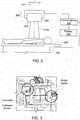
- Fig. 1 shows a prior art digital X-ray system 100 that includes an Overhead Tube Suspensory (OTS) system 101 for moving an X-ray source, an OTS console 102, a collimator 103 constituting the X-ray source (other components constituting the X-ray source are not shown due to the angle of view), a movable examining table 104, and a positioner 105 for moving the examining table 104.
- OTS Overhead Tube Suspensory
- the collimator 103 is typically mounted below the tube that emits X-rays, which impinges upon the patient through a shutter of the collimator 103, wherein the size of the shutter of the collimator 103 defines the irradiation range of X-rays, i.e., the size of the region of the field of view for exposure (FOV) 106.
- the lateral positions of the tube and the collimator determine the position of the field of view for exposure on the patient. It is well known that X-rays are harmful to human, thus it is required that X-rays are controlled so that it impinges only upon the part to be examined, of the patient, while its irradiation range should be large enough to satisfy all of regions to be examined.
- a radiographer is required to check whether the field of view for exposure 106 of X-ray is suitable or not.
- the radiographer turns on the illumination light of the collimator 103, and a collimator beam 107 will form an exposure region on the patient.
- the exposure region is consistent with the field of view for exposure 106 of the X-ray, so that whether the field of view for exposure 106 is suitable or not may be checked. If the field of view for exposure can not satisfy exposure requirement, the size and position of the field of view are required to be adjusted.
- the position of the X-ray source may be adjusted by manually moving the OTS and/or the positioner, to adjust the position of the FOV on the patient.
- an automatic positioning function which can help the radiographer in controlling the OTS so as to automatically move into the preset position.
- existing digital X-ray systems only can preset a limited number of positions for automatic positioning, and the preset position should be selected by a radiographer before automatically positioning at the preset position.
- a radiographer may often deal with various patients.
- the limited number of preset positions in the existing digital X-ray systems is far from satisfying clinical needs.
- a radiographer often needs to manually adjust the positioner of the X-ray system, in order to better adjust the position of the field of view for exposure.
- it may need to image several hundreds of patients every day, and during the diagnosis, the field of view for exposure of the X-ray system should be manually adjusted almost for each patient, which, for a radiographer, particularly for a female radiographer, is a huge challenge.
- each protocol in an X-ray system is provided with a default FOV value (i.e., the size of the FOV region).
- FOV value i.e., the size of the FOV region
- the default value may sometimes be not suitable for a patient whose body size is rather different.
- a radiographer is required to manually modify the FOV value, which will increase the time required for the whole examination and the work flow. If the radiographer is unwilling to manually modify the FOV value, some patients may expose to excessive dose of radiation which will be very dangerous.
- US2009/0232271 discloses X-ray imaging wherein the field of view of the X-ray exposure is automatically adjusted on the base of the desired region of interest.
- a method for automatically adjusting the field of view for exposure of an X-ray system comprising the steps of: capturing the image of a patient on the examining table of an X-ray system by an image sensor, wherein the image sensor is placed at a predetermined position in the X-ray system; displaying the captured image on a display for selection of a region of interest or a point of interest by a user on the image; automatically determining a target position of an X-ray source in response to the selection of the region of interest or the point of interest on the image, wherein the desired field of view for exposure covering the region of interest or the point of interest is obtained when the X-ray source is located at the target position; automatically locating the X-ray source at the target position in response to the determination of the target position.
- the step of automatically determining the target position of the X-ray source for the X-ray system comprises: determining the position of the center of the desired field of view for exposure on the image in response to the selection of the region of interest or the point of interest; and determining the target position of the X-ray source based on the position of the center of the desired field of view for exposure on the image and the imaging parameters of the image sensor.
- the step of determining the target position of the X-ray source based on the position of the center of the desired field of view for exposure on the image further comprises: determining the actual position of the center of the desired field of view for exposure on the patient based on the position of the center of the desired field of view for exposure on the image and the imaging parameters of the image sensor; and determining the target position of the X-ray source based on the actual position of the center of the desired field of view for exposure on the patient and the inherent positional relationship between the X-ray source and the center.
- the method for automatically adjusting the field of view for exposure of the X-ray system further comprises the steps of: automatically determining the size of the desired field of view for exposure in response to the selection of the region of interest on the image; and adjusting the size of a collimator shutter for the X-ray source in order to realize the size of the desired field of view for exposure.
- the step of automatically determining the size of the desired field of view for exposure comprises: determining the coordinates of the actual positions of the points which constitute the boundary of the region of interest on the patient, based on coordinates of positions of the points which constitute the boundary on the captured image, and imaging parameters of the image sensor; determining the actual size of the region of interest based on the coordinates of the actual positions; and determining the size of the desired field of view for exposure based on the actual size of the region of interest.
- the center of the desired field of view for exposure is the center of the region of interest or the point of interest.
- the method for automatically adjusting the field of view for exposure of the X-ray system further comprises the steps of: determining the position of the center of current field of view for exposure on the image based on the current position of the X-ray source and the imaging parameters of the image sensor; determining the size of the current field of view for exposure of the X-ray source on the image based on the current size of the collimator shutter of the X-ray source and the imaging parameter of the image sensor; and showing the size and the position of center of the current field of view for exposure on the captured image displayed on the display.
- determining the target position of the X-ray source comprises determining the moving distance of the X-ray source required for realizing the desired field of view for exposure, based on the current position and the target position of the X-ray source.
- the target position of the X-ray source refers to the target position of the X-ray source relative to the patient, wherein the X-ray source is moved the distance relative to the patient so as to be located at the target position, by moving the X-ray source via use of the overhead tube suspensory system and/or moving the patient via use of the positioner.
- the image sensor comprises two image sensors arranged at respective predetermined position, respectively, in the X-ray system.
- the step of automatically determining the target position of the X-ray source for the X-ray system comprises: determining respectively the positions of the center of desired field of view for exposure on the first and second images respectively captured by the two image sensors, in response to the selection of the region of interest or the point of interest; determining respectively the first target position corresponding to the first image and the second target position corresponding to the second image of the X-ray source, based on the positions of the center of the desired field of view for exposure on the first and second images and respective imaging parameters of the two image sensors; and obtaining the target position of the X-ray source by multiplying the first target position and the second target position respectively by corresponding predetermined weighting correction coefficients and summing the resultant products.
- the display may be a display of the local console of the X-ray system, a display of the workstation communicating with the local console or a display of the portable console communicating with the local console or the workstation.
- an X-ray system comprising: an X-ray source for emitting an X-ray to form a field of view for exposure on the patient; an image sensor arranged at a predetermined position in the X-ray system for capturing the image of the patient; a display for displaying the captured image of the patient for selection of a region of interest or a point of interest by a user on the image; a computing device configured to compute the target position of the X-ray source, wherein the desired field of view for exposure covering the region of interest or the point of interest is obtained when the X-ray source is located at the target position; a shifting device for locating the X-ray source at the target position; and a control device configured to control the computing device to start computing the target position in response to the selection of the region of interest or the point of interest, and to control the shifting device to locate the X-ray source at the target position in response to the computed target position.
- the display may be a display of the local console of the X-ray system, a display of the workstation communicating with the local console or a display of the portable console communicating with the local console or the workstation.
- the computing device further comprises: a center of desired field of view for exposure computing unit for computing the position of the center of the desired field of view for exposure on the image; and a target position computing unit for determining the target position of the X-ray source based on the position of the center of the desired field of view for exposure on the image and the imaging parameters of the image sensor.
- the X-ray system also comprises the size of desired field of view for exposure computing unit which is configured to automatically determine the size of the desired field of view for exposure in response to the selection of the region of interest on the image, wherein the control device adjusts the size of the collimator shutter of the X-ray source to realize the size of the desired field of view for exposure in response to the determination of the size of the desired field of view for exposure.
- the target position computing unit determines the actual position of the center of the desired field of view for exposure on the patient based on the position of the center of the desired field of view for exposure on the image and the imaging parameters of the image sensor, and then determines the target position of the X-ray source based on the actual position of the center of the desired field of view for exposure on the patient and the inherent positional relationship between the X-ray source and the center.
- the size of desired field of view for exposure computing unit determines the coordinates of the actual positions of the points which constitute the boundary of the region of interest on the patient, based on the coordinates of the positions of the points which constitute said boundary on the captured image and the imaging parameters of the image sensor; determines the actual size of the region of interest based on the coordinates of the actual position; and then determines the size of the desired field of view for exposure based on the actual size of the region of interest.
- the computing device also comprises: a center of current field of view for exposure computing unit for determining the position of the center of current field of view for exposure on the image based on the current position of the X-ray source and the imaging parameters of the image sensor; a size of current field of view for exposure computing unit for determining the size of the current field of view for exposure of the X-ray source on the image based on the current size of the collimator shutter of the X-ray source and the imaging parameter of the image sensor, wherein the control device shows the size and the center of the current field of view for exposure in the image displayed on the display, based on the computed size of the current field of view for exposure on the image and the position of its center on the image.
- the target position computing unit further computes the moving distance of the X-ray source required for realizing the desired field of view for exposure, based on the current position and the target position of the X-ray source.
- the target position of the X-ray source refers to the target position of the X-ray source relative to the patient
- the shifting device comprises an overhead tube suspensory system for moving the X-ray source and a positioner for moving the patient, and wherein the X-ray source is moved the distance relative to the patient so as to be located at the target position via the overhead tube suspensory system and/or the positioner.
- the image sensor comprises two image sensors respectively arranged at corresponding predetermined positions in the X-ray system, these two image sensor taking the first image and the second image of the patient.
- the computing device further comprises: a desired field of view for exposure computing unit for computing the positions of the center of the desired field of view for exposure respectively on the first and second images; and a target position computing unit for determining respectively the first target position corresponding to the first image and the second target position corresponding to the second image, of the X-ray source, based on the positions of the center of the desired field of view for exposure on the first and second images and the imaging parameters of the image sensor; a weighting computing unit for obtaining the target position of the X-ray source by multiplying the first target position and the second target position respectively by corresponding predetermined weighting correction coefficients and summing the resultant products.
- a field of view for exposure automatic adjusting device for an X-ray system comprising: an image sensor arranged at a predetermined position in the X-ray system, for capturing the image of the patient to be examined on the examining table, and for transmitting the captured image to a display for the selection of a region of interest or a point of interest by the user; a computing device configured to compute the target position of the X-ray source in the X-ray system, wherein the desired field of view for exposure covering the region of interest or the point of interest selected by the user is obtained when the X-ray source is located at the target position; a control device configured to control the computing device to start computing the target position in response to the selection of the region of interest or the point of interest by the user on the captured image, and to send a locating signal to the X-ray system to locate the X-ray source at the target position in response to the computed target position.
- various embodiments of the present invention may have one or more of the following advantages. Since the adjusting method, apparatus or X-ray system may automatically compute the proper target position of the X-ray source in response to the selection of the region of interest or the point of interest by the user on the captured image of the patient and automatically locate the X-ray source at the target position, the good adjustment of the position of the field of view for exposure of the X-ray may be achieved without requiring the radiographer to manually adjust the overhead tube suspensory system or positioner of the X-ray system. Furthermore, the present invention may also realize the automatic adjustment of the size of the field of view for exposure.
- the burden on the radiographer is alleviated, while avoiding any false operation and operational error possibly caused by manual adjustment.
- the radiographer may obtain the position and range of FOV directly from the display in the control room or diagnosis room. Therefore, the patient will not be annoyed or hurted due to appearance of laser cross cursor of the illumination light.
- the captured image may be transmitted to a remote display for selection of the region of interest or the point of interest by the user, remote and automatic adjustment of the field of view for exposure may be realized.
- a number of images or video images of the patient may be taken or captured continuously by the image sensor in the X-ray system or the automatic adjusting device according to the present invention.
- the user may select sharp images or grasp proper video frames for selection of the region of interest or the point of interest. This is particularly favorable for a restless patient (e.g., a crying infant).
- preferred embodiments of the present invention employ double image sensors. Combining images from two image sensors compensates for any distortion error, thereby improving the adjustment accuracy of the field of view for exposure.
- the image sensor according to embodiments of the present invention and post-processing modules are inexpensive. Therefore, the present invention provides an apparatus, method and system for automatically adjusting the field of view for exposure that are cost efficient.
- the apparatus, method and system for automatically adjusting the field of view for exposure enable the workflow of the X-ray system to be simpler, faster, more effective, and ease to use.
- Fig. 2 is a schematic diagram of an X-ray system 200 according to an embodiment of the present invention.
- the X-ray system 200 includes an overhead tube suspentory system 201, an X-ray source 202, an examining table 204, a positioner 207 for moving the examining table, a control device 204 and a display 205.
- the X-ray system 200 includes an image sensor 208, which is fixed at a predetermined position in the X-ray system, for imaging the patient on the examining table 204.
- the image sensor 208 may be any of now known or later developed apparatus that can take a image, hereinafter an embodiment of the present invention will be explained by taking a digital camera as an example of the image sensor 208.
- the camera 208 is fixed at a position where it can capture an image of the patient on the examining table 204, and a distance of the position from other devices in the X-ray system 200 is measurable or known.
- the camera 208 is fixed on the lower surface (i.e., the surface on which the collimator shutter is located) of the collimator 203 that is a part of the X-ray source, and is nearly flush with the surface.
- the distance of the camera 208 from the center of the collimator shutter is about several centimeters.
- the position of the center of the collimator shutter in the X-ray source is regarded as the position of the X-ray source, therefore, the projection of the position of the X-ray source upon the patient is just the position of the center of the field of view for exposure.
- position of other point on the X-ray source may be regarded as the position of the X-ray source, with the determination of the position of the center of the collimator shutter, it is easy to obtain the position of the point.
- the X-ray system 200 also includes a control device 205 and a display 206.
- the control device 205 and the display 206 are shown in Fig. 2 as being separated from the overhead tube suspensory system (OTS) 201 and the X-ray source 202 by a distance and communicating via cables, it will be appreciated by one skilled in the art that the control device 205 and the display 206 may be the control device and the display of the OTS console as shown in Fig. 1 , or may be the control and the display of the remote workstation in wired or wireless communication with the OTS console, or may also be the control device and the display of the portable console in wireless communication with the OTS console or the workstation, or any combination thereof.
- OTS overhead tube suspensory system
- Figs. 4 is a schematic diagram illustrating the image of the patient captured by the X-ray system according to embodiments of the present invention, which includes: a schematic diagram of the image on the display of the OTS console; a schematic diagram of the image on the display of the workstation; and an enlarged view of the captured image of the patient.
- An operator of the X-ray system 200 uses a pointing device, such as a mouse to select the desirable region of interest or point of interest on the image of the patient that is displayed on the display.
- a pointing device such as a mouse
- the operator may directly touch the touch screen with his/her finger or a device such as a pen to select the region of interest or the point of interest.
- the X-ray system 200 also includes a computing device 209 for computing the target position of the X-ray source corresponding to the selected region of interest or point of interest.
- the X-ray emitted therefrom forms the desired field of view for exposure on the patient, that is, the region of interest or the point of interest falls within the desired field of view for exposure.
- the control device 205 detects the selection of the region of interest or the point of interest, it sends to the computing device 209 a control signal to start computation.
- the computing device 209 receives the signal, it start computing the target position of the X-ray source, and returns the computed target position to the control device 205.
- the control device 205 subsequently controls the OTS 201 to move the X-ray source to the target position.
- the target position of the X-ray source is actually a relative position relative to the patient.
- the control device 205 may also move the patient by controlling the positioner 207 for moving the examining table 204, so as to locate the X-ray source at the target position, thereby obtaining the desired field of view for exposure.
- the control device 205 may also locate the X-ray source at the target position by simultaneously controlling both the OTS 201 and the positioner 207 to move both the X-ray source and the patient.
- the computing method of the target position of the X-ray source will be described in more detail below.
- To compute the target position of the X-ray source it is necessary to utilize the mutual relation between three-dimensional coordinates of a point in space and its corresponding two-dimensional coordinates of the image.
- To determine the mutual relation between three-dimensional coordinates of a point in space and its corresponding two-dimensional coordinates of the image it is required to build the geometrical model of the image sensor (taking the camera as an example) imaging, and determine the geometrical model parameters thereof (herein referred to as imaging parameters), this process is referred to as camera demarcating.
- the basic idea of a camera demarcating algorithm is to select a known object in space as a demarcating reference, on which the image processing and a series of mathematical transforming and computing methods are performed, so as to compute internal parameters and external parameters of the camera.
- the internal parameters include parameters such as a camera lens focus, a lens distortion coefficient, an image coordinate origin, and the external parameters include horizontal and rotating shift of the object relative to the camera lens.
- the mutual relation between three-dimensional coordinates of a point in space and its corresponding two-dimensional coordinates of the image, and then the imaging geometrical model and imaging parameters of the camera may be solved.
- the imaging geometrical model and the imaging parameters may be applied whenever the correspondence between the points of the image captured by the camera and the points in real world is applied later, as long as the lens of the camera is not replaced and the position of the camera in the X-ray system and the shooting angle of view of the camera remain unchanged.
- knowing the coordinates of a point on the image captured by the camera its coordinates in real world may be solved, and vice versa.
- the computing device 209 In response to selection of the region of interest or the point of interest in the image displayed on the display, the computing device 209 first computes the position of the center of the desired field of view for exposure on the image. In one embodiment, the position of the center of the selected region of interest on the image is calculated as the position of the center of the desired field of view for exposure on the image, or the position of the selected point of interest on the image is calculated as the position of the center of the desired field of view for exposure on the image. Then, the computing device 209 utilizes the stored imaging parameters and the imaging geometrical model to calculate the position of the center of the field of view for exposure in real world (i.e., the actual position on the patient), i.e. the projection position of the position of the X-ray source on the patient.
- real world i.e., the actual position on the patient
- the height of the X-ray source from the patient remains the same during adjustment. Therefore, knowing the projection position of the X-ray source, it is easy to obtain the real position of the X-ray source, i.e., the target position of the X-ray source.
- the computing device 209 also calculates the actual size of the desired field of view for exposure based on the selected region of interest. First, the computing device 209 computes the coordinates of positions of points which constitute a boundary of the region of interest, on the image, and then determines the coordinates of actual positions of these points on the patient based on the coordinates of the positions of the points on the image and the imaging geometrical model and the imaging parameters of the image sensor. Then, the computing device 209 determines the actual size of the region of interest based on the coordinates of the actual positions of the boundary points, and determines the size of the desired field of view for exposure based on the actual size of the region of interest.
- the size of the desired field of view for exposure is selected such that the desired field of view for exposure is entirely overlapped with, or slightly larger than, the region of interest.
- the relationship between the size of the region of the field of view for exposure and the size of the collimator shutter is known and fixed.
- the computing device 209 may compute the size to which the collimator shutter is adjusted. Therefore, the control device 205 adjusts the collimator, based on the computed size of the collimator shutter, such that the region of the desired field of view for exposure is substantially consistent with, or properly larger than, the region of interest.
- the known correspondence relation between the size of the collimator shutter and the size of the region of the field of view for exposure is obtained in advance via experiments, and stored in the X-ray system.
- the computing device 209 does not have to compute the coordinates of the positions of all boundary points, and instead, only need to compute the coordinates of the positions of some of the boundary points.
- the field of view for exposure and the selected region of interest are typically rectangle or square.
- the computing device 209 may only compute the coordinates of the positions of the four vertexes of the region of interest on the image, then respectively compute the corresponding coordinates of each vertex in real world, and then may compute the real size of the region of interest and determine the size of the region of the desired field of view for exposure based on the real size.
- the computing device 209 computes the coordinates of the positions of the center and each vertex of the current field of view for exposure based on the current position of the X-ray source and the size of the collimator shutter, and computes the positions of the center and each vertex on the image based on the imaging geometrical model and the imaging parameters of the camera.
- control device 205 may control the display to display the center and the region range of the current field of view for exposure on the patient image, based on the computed positions of the center and each vertex of the current field of view for exposure on the image. In this way, the operator may visually observe whether the current field of view satisfies requirements without turning on the illumination light of the collimator. If the requirements are satisfied, no adjustment is needed. If the requirements are not satisfied, the adjustment is made by selecting the region of interest or the point of interest on the image as described above.
- the X-ray system has the imaging geometrical model and the imaging parameters of the camera that are obtained by demarcating, and the height of the X-ray source from the examining table (i.e., the patient), the relationship between the size of the collimator shutter and the size of the region of the field of view for exposure and so on, stored thereon in advance.
- the camera 208 may be demarcated before the X-ray system according to the present invention is delivered, and the obtained imaging geometrical model and the imaging parameters are recorded in the X-ray system for use later by the computing device 209.
- parameters such as the current position of the X-ray source, the current size of the collimator shutter and the like are known to the X-ray system.
- the plane where the patient lies i.e., the plane where the examining table is located at
- the plane where the examining table is taken as the XY plane of the coordinate system, with a fixed point on the examining table being the origin
- a coordinate system may facilitate computation of the position and size of the field of view for exposure. Therefore, the coordinate of the center of the field of view for exposure on the Z axis of the world coordinate system is 0.
- the X, Y coordinates of the target position of the X-ray source equal to the X, Y coordinates of the desired field of view for exposure
- the Z coordinate of the target position of the X-ray source equals to the height h of the X-ray source from the examining table (i.e., from the patient). It should be appreciated that other planes may be taken as the XY plane, or other points may be taken as the origin.
- Equation (1) embodies the imaging geometrical model of the camera.
- the computing device 209 In response to the selection of the region of interest or the point of interest on the image displayed in the display, the computing device 209 first computes the position of the center of the selected region of interest on the image as the position of the center of the desired field of view for exposure on the image, or computes the position of the selected point of interest on the image as the position of the center of the desired field of view for exposure on the image.
- the position of the center of the field of view for exposure is the projection position of the position of the X-ray source on the surface of the patient's body. Therefore, the coordinates on X axis and Y axis of the target position of the X-ray source may also be X 0 , Y 0 , respectively.
- the coordinate of the target position of the X-ray source on Z axis is h. In this way, the target position of the X-ray source is obtained.
- the computing device 209 further computes the distance by which the X-ray source is moved so as to reach the target position. To this end, the computing device 209 calculates the moving distance ⁇ x and ⁇ y based on the coordinates respectively on X axis and Y axis of the current position and the target position of the X-ray source. And then, the control device controls a shifting device such as the positioner or the OTS to move the X-ray source by ⁇ x and ⁇ y on X axis and Y axis, respectively, relative to the patient.
- a shifting device such as the positioner or the OTS to move the X-ray source by ⁇ x and ⁇ y on X axis and Y axis, respectively, relative to the patient.
- the image sensor, the computing device, the control device and the display as described above may be made into separate modules and distributed across the X-ray system.
- the image sensor is located on the bottom surface of the collimator
- the computing device and the control device are located at the OTS console or the workstation communicating with the X-ray system
- the display is a display of the OTS console, the portable console or the workstation.
- the image sensor, the computing device and the control device may also be made into a self-contained module for automatically adjusting the field of view for exposure of the X-ray system, the module may be attached to the X-ray system via an interface and communicate with the X-ray system and the device provided with the display, so as to implement an embodiment of the present invention.
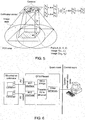
- FIG. 3 is a bottom view of the collimator having two image sensors, according to an embodiment of the present invention.
- two image sensors are arranged at different locations on the collimator. These two image sensors respectively capture images of the patient, and either of these two images is displayed on the display for selection of a region of interest or a point of interest by a user.
- the computing device After selection of the region of interest or the point of interest, the computing device computes the coordinates of the center of the desired field of view for exposure respectively on these two images, and computes two corresponding coordinates on the world coordinate system based on the imaging geometrical model and the imaging parameters of each of image sensors. Since distortion may occur during imaging of each camera, the computed two coordinates of the world coordinate system may not equal to each other. By combining the two coordinates of the world coordinate system to compute the final position of the center of the desired field of view for exposure, distortion error may be compensated for to some extent. For example, the final position of the center of the desired field of view for exposure may be obtained by averaging these two coordinates of the world coordinate system, or multiplying them respectively by respective weighting coefficient generated through experiments.
- Fig. 5 is a schematic diagram illustrating the computation of the position and size of the field of view for exposure in the case of two image sensors, according to an embodiment of the present invention.
- coefficients B and C are also referred to as correction coefficients, once these coefficients are determined during demarcating, they, similar to parameter(s) A, are also recorded and may be applied to any subsequent X-ray examination.
- the final coordinates of the center of the desired field of view for exposure may be obtained.
- the X and Y coordinates of the center of the desired field of view for exposure are the X and Y coordinates of the target position of the X-ray source.
- the range of the corrected desired field of view for exposure may also be computed.
- distortion error may be reduced or compensated for, and the accuracy with which the field of view for exposure is adjusted may be improved.
- the image sensor may not only take a single digital image, but also take a plurality of digital images or video images, and display them on the display.
- the user may select a proper digital image or select a frame of image in the video as the image from which the region of interest or the point of interest is selected.
- Fig. 6 is a schematic diagram of a communication line of the X-ray system according to an embodiment of the present invention.
- two image sensors 1 and 2 transmit the taken image or video to the OTS console, from which it is in turn transmitted to the display of the portable console or workstation.
- Two image sensors 1 and 2 mounted on the collimator may be connected to the AV1 interface and the AV2 interface of the OTS console respectively via the AV cable 1 and the AV cable 2.
- the OTS console converts the AV data from the image sensors to the Ethernet data, and transmits it to the portable console or workstation via the Ethernet video cable.
- Fig. 7 is a schematic flowchart illustrating a method of automatically adjusting the field of view for exposure according to an embodiment of the present invention.
- Step 701 an image of a patient on an examining table of an X-ray system is captured by an image sensor.
- Step 702 the position of the center of a current field of view for exposure on the image and the covering range of the current field of view for exposure on the image are determined based on the current position of the X-ray source, the size of the collimator shutter and the imaging parameters of the image sensor.
- the captured image is displayed on the display (Step 703), in which the current field of view for exposure is identified on the image.
- the user observes whether the current field of view for exposure on the image satisfies requirements, and if so, the flow ends; if not, the user selects the region of interest or the point of interest on the image (Step 704).
- the target position of the X-ray source of the X-ray system corresponding to the desired field of view for exposure is automatically determined (Step 705), and when the X-ray source is located at the target position, the region of interest or the point of interest falls within the desired field of view for exposure.
- the coordinates of the position of the center of the desired field of view for exposure, within which the region of interest or the point of interest falls, on the image are first determined; and then based on the coordinates of the position and the imaging parameters of the image sensor, the coordinates of the position of the center of the desired field of view for exposure on the world coordinate system are determined; and the coordinates of the target position of the X-ray source are subsequently determined based on the known position correspondence relation between the X-ray source and the center of the field of view for exposure.
- the coordinates of the center of the region of interest on the image or the coordinates of the point of interest on the image may be taken as the coordinates of the position of the center of the desired field of view for exposure on the image.
- the region size of the desired field of view for exposure is determined based on the imaging parameters (Step 706).
- Step 705 and 706 may be simultaneously or sequentially performed, either Step 705 or Step 706 may be performed first.
- the X-ray source is automatically located at the target position (Step 707).
- the region of the field of view for exposure may be adjusted to the desired size (Step 708), e.g., by adjusting the size of the collimator shutter.
- Step 707 and 708 are performed in random order.
- Step 702, 706, 708 may not be performed.
- Various aspects of the present invention are to utilize a video aided technology to help user automatically adjust the field of view for exposure. It is known from the above description, in accordance with the present invention, a user can perform the X-ray examination on a patient without manually adjusting the position and the region size of the field of view for exposure and without turning on the illumination light of the collimator, and may perform the adjustment remotely.
- Various embodiments of the present invention have one or more of the advantages described above.
Landscapes
- Health & Medical Sciences (AREA)
- Life Sciences & Earth Sciences (AREA)
- Engineering & Computer Science (AREA)
- Medical Informatics (AREA)
- Radiology & Medical Imaging (AREA)
- Molecular Biology (AREA)
- Biophysics (AREA)
- Nuclear Medicine, Radiotherapy & Molecular Imaging (AREA)
- Optics & Photonics (AREA)
- Pathology (AREA)
- Physics & Mathematics (AREA)
- Biomedical Technology (AREA)
- Heart & Thoracic Surgery (AREA)
- High Energy & Nuclear Physics (AREA)
- Surgery (AREA)
- Animal Behavior & Ethology (AREA)
- General Health & Medical Sciences (AREA)
- Public Health (AREA)
- Veterinary Medicine (AREA)
- Human Computer Interaction (AREA)
- Computer Vision & Pattern Recognition (AREA)
- Apparatus For Radiation Diagnosis (AREA)
Description
- The present invention generally relates to the field of an X-ray system, and in particular to a method and apparatus for adjusting a field of view for exposure of an x-ray system, and an X-ray system.
-
Fig. 1 shows a prior art digital X-ray system 100 that includes an Overhead Tube Suspensory (OTS)system 101 for moving an X-ray source, anOTS console 102, acollimator 103 constituting the X-ray source (other components constituting the X-ray source are not shown due to the angle of view), a movable examining table 104, and apositioner 105 for moving the examining table 104. Thecollimator 103 is typically mounted below the tube that emits X-rays, which impinges upon the patient through a shutter of thecollimator 103, wherein the size of the shutter of thecollimator 103 defines the irradiation range of X-rays, i.e., the size of the region of the field of view for exposure (FOV) 106. The lateral positions of the tube and the collimator determine the position of the field of view for exposure on the patient. It is well known that X-rays are harmful to human, thus it is required that X-rays are controlled so that it impinges only upon the part to be examined, of the patient, while its irradiation range should be large enough to satisfy all of regions to be examined. - In the current digital X-ray system 100, for each X-ray examination, a radiographer is required to check whether the field of view for
exposure 106 of X-ray is suitable or not. During checking, the radiographer turns on the illumination light of thecollimator 103, and acollimator beam 107 will form an exposure region on the patient. The exposure region is consistent with the field of view forexposure 106 of the X-ray, so that whether the field of view forexposure 106 is suitable or not may be checked. If the field of view for exposure can not satisfy exposure requirement, the size and position of the field of view are required to be adjusted. The position of the X-ray source may be adjusted by manually moving the OTS and/or the positioner, to adjust the position of the FOV on the patient. For an advanced X-ray system, it is often equipped with an automatic positioning function, which can help the radiographer in controlling the OTS so as to automatically move into the preset position. However, existing digital X-ray systems only can preset a limited number of positions for automatic positioning, and the preset position should be selected by a radiographer before automatically positioning at the preset position. - For a hospital with heavy load, a radiographer may often deal with various patients. The limited number of preset positions in the existing digital X-ray systems is far from satisfying clinical needs. In addition, during the practical operation, a radiographer often needs to manually adjust the positioner of the X-ray system, in order to better adjust the position of the field of view for exposure. Generally, in some hospitals, it may need to image several hundreds of patients every day, and during the diagnosis, the field of view for exposure of the X-ray system should be manually adjusted almost for each patient, which, for a radiographer, particularly for a female radiographer, is a huge challenge.
- In addition, when a radiographer wants to ensure that the region of the field of view is acceptable, he needs to turn on the lamp of the collimator, and at this time, a laser cross cursor for demarcating the position of the detector appears; however, the laser cross cursor is not patient friendly, and sometimes may hurt eyes of the patient. Currently, each protocol in an X-ray system is provided with a default FOV value (i.e., the size of the FOV region). However, the default value may sometimes be not suitable for a patient whose body size is rather different. At this time, a radiographer is required to manually modify the FOV value, which will increase the time required for the whole examination and the work flow. If the radiographer is unwilling to manually modify the FOV value, some patients may expose to excessive dose of radiation which will be very dangerous.
-
US2009/0232271 discloses X-ray imaging wherein the field of view of the X-ray exposure is automatically adjusted on the base of the desired region of interest. - To address one or more of the above-mentioned problems, according to an aspect of the present invention, there is provided a method for automatically adjusting the field of view for exposure of an X-ray system, comprising the steps of: capturing the image of a patient on the examining table of an X-ray system by an image sensor, wherein the image sensor is placed at a predetermined position in the X-ray system; displaying the captured image on a display for selection of a region of interest or a point of interest by a user on the image; automatically determining a target position of an X-ray source in response to the selection of the region of interest or the point of interest on the image, wherein the desired field of view for exposure covering the region of interest or the point of interest is obtained when the X-ray source is located at the target position; automatically locating the X-ray source at the target position in response to the determination of the target position.
- According to an embodiment of the present invention, the step of automatically determining the target position of the X-ray source for the X-ray system comprises: determining the position of the center of the desired field of view for exposure on the image in response to the selection of the region of interest or the point of interest; and determining the target position of the X-ray source based on the position of the center of the desired field of view for exposure on the image and the imaging parameters of the image sensor.
- According to an embodiment, the step of determining the target position of the X-ray source based on the position of the center of the desired field of view for exposure on the image further comprises: determining the actual position of the center of the desired field of view for exposure on the patient based on the position of the center of the desired field of view for exposure on the image and the imaging parameters of the image sensor; and determining the target position of the X-ray source based on the actual position of the center of the desired field of view for exposure on the patient and the inherent positional relationship between the X-ray source and the center.
- According to an embodiment of the present invention, the method for automatically adjusting the field of view for exposure of the X-ray system further comprises the steps of: automatically determining the size of the desired field of view for exposure in response to the selection of the region of interest on the image; and adjusting the size of a collimator shutter for the X-ray source in order to realize the size of the desired field of view for exposure.
- According to an embodiment of the present invention, the step of automatically determining the size of the desired field of view for exposure comprises: determining the coordinates of the actual positions of the points which constitute the boundary of the region of interest on the patient, based on coordinates of positions of the points which constitute the boundary on the captured image, and imaging parameters of the image sensor; determining the actual size of the region of interest based on the coordinates of the actual positions; and determining the size of the desired field of view for exposure based on the actual size of the region of interest.
- According to an embodiment of the present invention, the center of the desired field of view for exposure is the center of the region of interest or the point of interest.
- According to an embodiment of the present invention, the method for automatically adjusting the field of view for exposure of the X-ray system further comprises the steps of: determining the position of the center of current field of view for exposure on the image based on the current position of the X-ray source and the imaging parameters of the image sensor; determining the size of the current field of view for exposure of the X-ray source on the image based on the current size of the collimator shutter of the X-ray source and the imaging parameter of the image sensor; and showing the size and the position of center of the current field of view for exposure on the captured image displayed on the display.
- According to an embodiment of the present invention, determining the target position of the X-ray source comprises determining the moving distance of the X-ray source required for realizing the desired field of view for exposure, based on the current position and the target position of the X-ray source.
- According to an embodiment of the present invention, the target position of the X-ray source refers to the target position of the X-ray source relative to the patient, wherein the X-ray source is moved the distance relative to the patient so as to be located at the target position, by moving the X-ray source via use of the overhead tube suspensory system and/or moving the patient via use of the positioner.
- According to an embodiment of the present invention, the image sensor comprises two image sensors arranged at respective predetermined position, respectively, in the X-ray system.
- According to an embodiment of the present invention, the step of automatically determining the target position of the X-ray source for the X-ray system comprises: determining respectively the positions of the center of desired field of view for exposure on the first and second images respectively captured by the two image sensors, in response to the selection of the region of interest or the point of interest; determining respectively the first target position corresponding to the first image and the second target position corresponding to the second image of the X-ray source, based on the positions of the center of the desired field of view for exposure on the first and second images and respective imaging parameters of the two image sensors; and obtaining the target position of the X-ray source by multiplying the first target position and the second target position respectively by corresponding predetermined weighting correction coefficients and summing the resultant products.
- According to an embodiment of the present invention, the display may be a display of the local console of the X-ray system, a display of the workstation communicating with the local console or a display of the portable console communicating with the local console or the workstation.
- According to another aspect of the invention, there is provided an X-ray system comprising: an X-ray source for emitting an X-ray to form a field of view for exposure on the patient; an image sensor arranged at a predetermined position in the X-ray system for capturing the image of the patient; a display for displaying the captured image of the patient for selection of a region of interest or a point of interest by a user on the image; a computing device configured to compute the target position of the X-ray source, wherein the desired field of view for exposure covering the region of interest or the point of interest is obtained when the X-ray source is located at the target position; a shifting device for locating the X-ray source at the target position; and a control device configured to control the computing device to start computing the target position in response to the selection of the region of interest or the point of interest, and to control the shifting device to locate the X-ray source at the target position in response to the computed target position.
- According to an embodiment of the present invention, the display may be a display of the local console of the X-ray system, a display of the workstation communicating with the local console or a display of the portable console communicating with the local console or the workstation.
- According to an embodiment of the present invention, the computing device further comprises: a center of desired field of view for exposure computing unit for computing the position of the center of the desired field of view for exposure on the image; and a target position computing unit for determining the target position of the X-ray source based on the position of the center of the desired field of view for exposure on the image and the imaging parameters of the image sensor.
- According to an embodiment of the present invention, the X-ray system also comprises the size of desired field of view for exposure computing unit which is configured to automatically determine the size of the desired field of view for exposure in response to the selection of the region of interest on the image, wherein the control device adjusts the size of the collimator shutter of the X-ray source to realize the size of the desired field of view for exposure in response to the determination of the size of the desired field of view for exposure.
- According to an embodiment of the present invention, the target position computing unit determines the actual position of the center of the desired field of view for exposure on the patient based on the position of the center of the desired field of view for exposure on the image and the imaging parameters of the image sensor, and then determines the target position of the X-ray source based on the actual position of the center of the desired field of view for exposure on the patient and the inherent positional relationship between the X-ray source and the center.
- According to an embodiment of the present invention, the size of desired field of view for exposure computing unit determines the coordinates of the actual positions of the points which constitute the boundary of the region of interest on the patient, based on the coordinates of the positions of the points which constitute said boundary on the captured image and the imaging parameters of the image sensor; determines the actual size of the region of interest based on the coordinates of the actual position; and then determines the size of the desired field of view for exposure based on the actual size of the region of interest.
- According to an embodiment of the present invention, the computing device also comprises: a center of current field of view for exposure computing unit for determining the position of the center of current field of view for exposure on the image based on the current position of the X-ray source and the imaging parameters of the image sensor; a size of current field of view for exposure computing unit for determining the size of the current field of view for exposure of the X-ray source on the image based on the current size of the collimator shutter of the X-ray source and the imaging parameter of the image sensor, wherein the control device shows the size and the center of the current field of view for exposure in the image displayed on the display, based on the computed size of the current field of view for exposure on the image and the position of its center on the image.
- According to an embodiment of the present invention, the target position computing unit further computes the moving distance of the X-ray source required for realizing the desired field of view for exposure, based on the current position and the target position of the X-ray source.
- According to an embodiment of the present invention, the target position of the X-ray source refers to the target position of the X-ray source relative to the patient, wherein the shifting device comprises an overhead tube suspensory system for moving the X-ray source and a positioner for moving the patient, and wherein the X-ray source is moved the distance relative to the patient so as to be located at the target position via the overhead tube suspensory system and/or the positioner.
- According to an embodiment of the present invention, the image sensor comprises two image sensors respectively arranged at corresponding predetermined positions in the X-ray system, these two image sensor taking the first image and the second image of the patient.
- According to an embodiment of the present invention, the computing device further comprises: a desired field of view for exposure computing unit for computing the positions of the center of the desired field of view for exposure respectively on the first and second images; and a target position computing unit for determining respectively the first target position corresponding to the first image and the second target position corresponding to the second image, of the X-ray source, based on the positions of the center of the desired field of view for exposure on the first and second images and the imaging parameters of the image sensor; a weighting computing unit for obtaining the target position of the X-ray source by multiplying the first target position and the second target position respectively by corresponding predetermined weighting correction coefficients and summing the resultant products.
- According to yet another aspect of the present invention, there is provided a field of view for exposure automatic adjusting device for an X-ray system comprising: an image sensor arranged at a predetermined position in the X-ray system, for capturing the image of the patient to be examined on the examining table, and for transmitting the captured image to a display for the selection of a region of interest or a point of interest by the user; a computing device configured to compute the target position of the X-ray source in the X-ray system, wherein the desired field of view for exposure covering the region of interest or the point of interest selected by the user is obtained when the X-ray source is located at the target position; a control device configured to control the computing device to start computing the target position in response to the selection of the region of interest or the point of interest by the user on the captured image, and to send a locating signal to the X-ray system to locate the X-ray source at the target position in response to the computed target position.
- In comparison with the prior art, various embodiments of the present invention may have one or more of the following advantages. Since the adjusting method, apparatus or X-ray system may automatically compute the proper target position of the X-ray source in response to the selection of the region of interest or the point of interest by the user on the captured image of the patient and automatically locate the X-ray source at the target position, the good adjustment of the position of the field of view for exposure of the X-ray may be achieved without requiring the radiographer to manually adjust the overhead tube suspensory system or positioner of the X-ray system. Furthermore, the present invention may also realize the automatic adjustment of the size of the field of view for exposure. As no manual adjustment is needed, the burden on the radiographer is alleviated, while avoiding any false operation and operational error possibly caused by manual adjustment. In addition, it is not required to turn on the illumination light of the collimator of the X-ray source during automatic adjustment, the radiographer may obtain the position and range of FOV directly from the display in the control room or diagnosis room. Therefore, the patient will not be annoyed or hurted due to appearance of laser cross cursor of the illumination light. Furthermore, as the captured image may be transmitted to a remote display for selection of the region of interest or the point of interest by the user, remote and automatic adjustment of the field of view for exposure may be realized.
- Furthermore, a number of images or video images of the patient may be taken or captured continuously by the image sensor in the X-ray system or the automatic adjusting device according to the present invention. The user may select sharp images or grasp proper video frames for selection of the region of interest or the point of interest. This is particularly favorable for a restless patient (e.g., a crying infant).
- Furthermore, preferred embodiments of the present invention employ double image sensors. Combining images from two image sensors compensates for any distortion error, thereby improving the adjustment accuracy of the field of view for exposure.
- In addition, the image sensor according to embodiments of the present invention and post-processing modules (e.g., a computing device, a control device, and the like) are inexpensive. Therefore, the present invention provides an apparatus, method and system for automatically adjusting the field of view for exposure that are cost efficient.
- Finally, the apparatus, method and system for automatically adjusting the field of view for exposure according to embodiments of the present invention enable the workflow of the X-ray system to be simpler, faster, more effective, and ease to use.
- The content of this disclosure will be understood more thoroughly from reading the following detailed description in conjunction with accompanying drawings, wherein:
-
Fig. 1 is a schematic diagram of a prior art X-ray system, in which the field of view for exposure of the X-ray system needs to be adjusted manually; -
Fig. 2 is a schematic diagram of an X-ray system that may automatically adjust the field of view for exposure as needed, according to an embodiment of the present invention; -
Fig. 3 is a bottom view of a collimator of an X-ray system according to an embodiment of the present invention; -
Fig. 4 is a schematic diagram of a image of a patient captured by an X-ray system according to embodiments of the present invention; -
Fig. 5 is a schematic diagram illustrating computation of position and size of the field of view for exposure based on the captured image of the patient, according to an embodiment of the present invention; -
Fig. 6 is a schematic diagram of a communication line of the X-ray system according to an embodiment of the present invention; and -
Fig. 7 is a schematic flowchart illustrating a method of automatically adjusting the field of view for exposure according to an embodiment of the present invention. - Specific embodiments of the present invention will be described in detail below, but the present invention should not be limited to the following specific embodiments.
-
Fig. 2 is a schematic diagram of an X-ray system 200 according to an embodiment of the present invention. As shown in the figure, the X-ray system 200 includes an overheadtube suspentory system 201, anX-ray source 202, an examining table 204, apositioner 207 for moving the examining table, acontrol device 204 and adisplay 205. In addition, the X-ray system 200 includes animage sensor 208, which is fixed at a predetermined position in the X-ray system, for imaging the patient on the examining table 204. Theimage sensor 208 may be any of now known or later developed apparatus that can take a image, hereinafter an embodiment of the present invention will be explained by taking a digital camera as an example of theimage sensor 208. Thecamera 208 is fixed at a position where it can capture an image of the patient on the examining table 204, and a distance of the position from other devices in the X-ray system 200 is measurable or known. In the embodiment shown inFig. 2 , thecamera 208 is fixed on the lower surface (i.e., the surface on which the collimator shutter is located) of thecollimator 203 that is a part of the X-ray source, and is nearly flush with the surface. In one embodiment, the distance of thecamera 208 from the center of the collimator shutter is about several centimeters. For simplicity, in the following embodiments, the position of the center of the collimator shutter in the X-ray source is regarded as the position of the X-ray source, therefore, the projection of the position of the X-ray source upon the patient is just the position of the center of the field of view for exposure. Of course, position of other point on the X-ray source may be regarded as the position of the X-ray source, with the determination of the position of the center of the collimator shutter, it is easy to obtain the position of the point. - The X-ray system 200 also includes a
control device 205 and adisplay 206. Although thecontrol device 205 and thedisplay 206 are shown inFig. 2 as being separated from the overhead tube suspensory system (OTS) 201 and theX-ray source 202 by a distance and communicating via cables, it will be appreciated by one skilled in the art that thecontrol device 205 and thedisplay 206 may be the control device and the display of the OTS console as shown inFig. 1 , or may be the control and the display of the remote workstation in wired or wireless communication with the OTS console, or may also be the control device and the display of the portable console in wireless communication with the OTS console or the workstation, or any combination thereof. - The image of the patient captured by the
camera 208 is transmitted to thecontrol device 205 and displayed on thedisplay 206.Figs. 4 is a schematic diagram illustrating the image of the patient captured by the X-ray system according to embodiments of the present invention, which includes: a schematic diagram of the image on the display of the OTS console; a schematic diagram of the image on the display of the workstation; and an enlarged view of the captured image of the patient. - An operator of the X-ray system 200 uses a pointing device, such as a mouse to select the desirable region of interest or point of interest on the image of the patient that is displayed on the display. In addition, in the case where the display is a touch screen, the operator may directly touch the touch screen with his/her finger or a device such as a pen to select the region of interest or the point of interest.
- Returning to
Fig. 2 , the X-ray system 200 also includes a computing device 209 for computing the target position of the X-ray source corresponding to the selected region of interest or point of interest. When the X-ray source is at the target position, the X-ray emitted therefrom forms the desired field of view for exposure on the patient, that is, the region of interest or the point of interest falls within the desired field of view for exposure. After thecontrol device 205 detects the selection of the region of interest or the point of interest, it sends to the computing device 209 a control signal to start computation. After the computing device 209 receives the signal, it start computing the target position of the X-ray source, and returns the computed target position to thecontrol device 205. Thecontrol device 205 subsequently controls theOTS 201 to move the X-ray source to the target position. The target position of the X-ray source is actually a relative position relative to the patient. In another embodiment, thecontrol device 205 may also move the patient by controlling thepositioner 207 for moving the examining table 204, so as to locate the X-ray source at the target position, thereby obtaining the desired field of view for exposure. In other embodiments, thecontrol device 205 may also locate the X-ray source at the target position by simultaneously controlling both theOTS 201 and thepositioner 207 to move both the X-ray source and the patient. - The computing method of the target position of the X-ray source will be described in more detail below. To compute the target position of the X-ray source, it is necessary to utilize the mutual relation between three-dimensional coordinates of a point in space and its corresponding two-dimensional coordinates of the image. To determine the mutual relation between three-dimensional coordinates of a point in space and its corresponding two-dimensional coordinates of the image, it is required to build the geometrical model of the image sensor (taking the camera as an example) imaging, and determine the geometrical model parameters thereof (herein referred to as imaging parameters), this process is referred to as camera demarcating.
- The basic idea of a camera demarcating algorithm is to select a known object in space as a demarcating reference, on which the image processing and a series of mathematical transforming and computing methods are performed, so as to compute internal parameters and external parameters of the camera. The internal parameters include parameters such as a camera lens focus, a lens distortion coefficient, an image coordinate origin, and the external parameters include horizontal and rotating shift of the object relative to the camera lens.
- The accuracy of the camera demarcating has great influence on subsequent processing, and is one of very critical steps. To select a demarcating algorithm satisfying requirements, the inventor investigates a variety of demarcating algorithms outlined as follows:
- 1. Demarcating method utilizing a optimization algorithm:
- The method proposed by FAIG is a typical example of this kind of technology, this method utilizes coplanar constraint condition of a pinhole camera model. It is assumed that the optical imaging model of a camera is very complicated, considering various factors during imaging of the camera, each image requires 17 parameters to complete the demarcating function, and is computation intensive.
An advantage of this algorithm is being capable of assuming the optical imaging model of a camera is very complicated. However, its disadvantage is that the result of demarcating depends on the initially given value, and if the initially given value is not proper, it is difficult to get the correct result through optimization; in addition, the optimization program is time-consuming, and the result can not be given in real time. - 2. Direct linear transforming method:
- Karara proposed that directly solving a linear transformation may complete the solution of the model parameters in camera demarcating, which is attractive. A disadvantage of the method is that the influence of non-linear distortion factors of the lens is not considered, thus there is a relatively larger error. When there is high requirement on the accuracy, the linear model often cannot exactly describe the correspondence relation between geometrical model computations, therefore a non-linear model should be used.
- 3. Two-step method:
- Tsai proposed a two-step method based on radial constraint condition. The method first utilizes the radial constrain condition to solve the external parameters of the camera, and then solve other parameters of the camera. The method has a high accuracy, but a disadvantage is high requirements on equipment. Therefore, the accuracy of the method is at the cost of the complexity of the algorithm and equipment.
- 4. Zhengyou Zhang's demarcating method
This method assumes that the demarcating plate plane is in the world coordinate system, z = 0, the optimal solution of the parameters is computed by a linear model, and then non-linear refinement is performed based on the maximum likelihood method. This method first demarcates and solves the distortion parameters, and then solves internal and external parameters of the camera. The method is very robust, requires no expensive precise demarcating block, and is practical. However, the model assumes that a straight line remain the same after imaging by the camera, there is large error for a wide-angle camera. For Zhengyou Zhang's demarcaing method, see Zhengyou Zhang's "Flexible Camera Calibration By Viewing a Plane From Unknown Orientations", 0-7695-0164-8/99 (c) 1999 IEEE. - With the use of various demarcating methods described above, the mutual relation between three-dimensional coordinates of a point in space and its corresponding two-dimensional coordinates of the image, and then the imaging geometrical model and imaging parameters of the camera may be solved. The imaging geometrical model and the imaging parameters may be applied whenever the correspondence between the points of the image captured by the camera and the points in real world is applied later, as long as the lens of the camera is not replaced and the position of the camera in the X-ray system and the shooting angle of view of the camera remain unchanged. In case that the imaging geometrical model and the imaging parameters of the camera are demarcated, knowing the coordinates of a point on the image captured by the camera, its coordinates in real world may be solved, and vice versa.
- In response to selection of the region of interest or the point of interest in the image displayed on the display, the computing device 209 first computes the position of the center of the desired field of view for exposure on the image. In one embodiment, the position of the center of the selected region of interest on the image is calculated as the position of the center of the desired field of view for exposure on the image, or the position of the selected point of interest on the image is calculated as the position of the center of the desired field of view for exposure on the image. Then, the computing device 209 utilizes the stored imaging parameters and the imaging geometrical model to calculate the position of the center of the field of view for exposure in real world (i.e., the actual position on the patient), i.e. the projection position of the position of the X-ray source on the patient. In the present invention, the height of the X-ray source from the patient remains the same during adjustment. Therefore, knowing the projection position of the X-ray source, it is easy to obtain the real position of the X-ray source, i.e., the target position of the X-ray source.
- In one embodiment, the computing device 209 also calculates the actual size of the desired field of view for exposure based on the selected region of interest. First, the computing device 209 computes the coordinates of positions of points which constitute a boundary of the region of interest, on the image, and then determines the coordinates of actual positions of these points on the patient based on the coordinates of the positions of the points on the image and the imaging geometrical model and the imaging parameters of the image sensor. Then, the computing device 209 determines the actual size of the region of interest based on the coordinates of the actual positions of the boundary points, and determines the size of the desired field of view for exposure based on the actual size of the region of interest. Typically, the size of the desired field of view for exposure is selected such that the desired field of view for exposure is entirely overlapped with, or slightly larger than, the region of interest. For a given X-ray system, the relationship between the size of the region of the field of view for exposure and the size of the collimator shutter is known and fixed. According to the relationship and based on the size of the region of the desired field of view for exposure, the computing device 209 may compute the size to which the collimator shutter is adjusted. Therefore, the
control device 205 adjusts the collimator, based on the computed size of the collimator shutter, such that the region of the desired field of view for exposure is substantially consistent with, or properly larger than, the region of interest. The known correspondence relation between the size of the collimator shutter and the size of the region of the field of view for exposure is obtained in advance via experiments, and stored in the X-ray system. - Generally, the computing device 209 does not have to compute the coordinates of the positions of all boundary points, and instead, only need to compute the coordinates of the positions of some of the boundary points. For example, the field of view for exposure and the selected region of interest are typically rectangle or square. In this case, the computing device 209 may only compute the coordinates of the positions of the four vertexes of the region of interest on the image, then respectively compute the corresponding coordinates of each vertex in real world, and then may compute the real size of the region of interest and determine the size of the region of the desired field of view for exposure based on the real size. Although rectangle or square region of interest and region of the field of view for exposure are taken as examples hereinabove, it will be appreciated by those skilled in the art that other shapes of the region of interest and the region of the field of view for exposure may be feasible, and the computing method thereof is similar to those described above, and will not be repeated here.
- According to a preferred embodiment of the present invention, before an operator selects a region of interest or a point of interest, the position and the region range of a current field of view for exposure are also displayed on the patient image in the display. Therefore, the computing device 209 computes the coordinates of the positions of the center and each vertex of the current field of view for exposure based on the current position of the X-ray source and the size of the collimator shutter, and computes the positions of the center and each vertex on the image based on the imaging geometrical model and the imaging parameters of the camera. Thus, the
control device 205 may control the display to display the center and the region range of the current field of view for exposure on the patient image, based on the computed positions of the center and each vertex of the current field of view for exposure on the image. In this way, the operator may visually observe whether the current field of view satisfies requirements without turning on the illumination light of the collimator. If the requirements are satisfied, no adjustment is needed. If the requirements are not satisfied, the adjustment is made by selecting the region of interest or the point of interest on the image as described above. - In the foregoing explanation, the X-ray system has the imaging geometrical model and the imaging parameters of the camera that are obtained by demarcating, and the height of the X-ray source from the examining table (i.e., the patient), the relationship between the size of the collimator shutter and the size of the region of the field of view for exposure and so on, stored thereon in advance. For example, the
camera 208 may be demarcated before the X-ray system according to the present invention is delivered, and the obtained imaging geometrical model and the imaging parameters are recorded in the X-ray system for use later by the computing device 209. In addition, parameters such as the current position of the X-ray source, the current size of the collimator shutter and the like are known to the X-ray system. - In one embodiment, when the camera is demarcated, the plane where the patient lies (i.e., the plane where the examining table is located at) is taken as the XY plane of the coordinate system, with a fixed point on the examining table being the origin, since what is taken by the
camera 208 in the X-ray system is the image of the patient, such a coordinate system may facilitate computation of the position and size of the field of view for exposure. Therefore, the coordinate of the center of the field of view for exposure on the Z axis of the world coordinate system is 0. The X, Y coordinates of the target position of the X-ray source equal to the X, Y coordinates of the desired field of view for exposure, the Z coordinate of the target position of the X-ray source equals to the height h of the X-ray source from the examining table (i.e., from the patient). It should be appreciated that other planes may be taken as the XY plane, or other points may be taken as the origin. - In the case of using the above coordinate system, the relationship between the coordinates


- In response to the selection of the region of interest or the point of interest on the image displayed in the display, the computing device 209 first computes the position of the center of the selected region of interest on the image as the position of the center of the desired field of view for exposure on the image, or computes the position of the selected point of interest on the image as the position of the center of the desired field of view for exposure on the image. Then, the computing device 209 utilizes the stored imaging parameter(s) A to compute the position of the center of the field of view for exposure in the real world (i.e., the actual position on the patient) based on Equation (1), that is:


camera 208. - As described earlier, the position of the center of the field of view for exposure is the projection position of the position of the X-ray source on the surface of the patient's body. Therefore, the coordinates on X axis and Y axis of the target position of the X-ray source may also be X0, Y0, respectively. In addition, since the height h of the X-ray source from the plane where the patient lies remains unchanged and is known, therefore, it is known that the coordinate of the target position of the X-ray source on Z axis is h. In this way, the target position of the X-ray source is obtained.
- In one embodiment, the computing device 209 further computes the distance by which the X-ray source is moved so as to reach the target position. To this end, the computing device 209 calculates the moving distance Δx and Δy based on the coordinates respectively on X axis and Y axis of the current position and the target position of the X-ray source. And then, the control device controls a shifting device such as the positioner or the OTS to move the X-ray source by Δx and Δy on X axis and Y axis, respectively, relative to the patient.
- During production, the image sensor, the computing device, the control device and the display as described above may be made into separate modules and distributed across the X-ray system. For example, the image sensor is located on the bottom surface of the collimator, the computing device and the control device are located at the OTS console or the workstation communicating with the X-ray system, and the display is a display of the OTS console, the portable console or the workstation. Alternatively, the image sensor, the computing device and the control device may also be made into a self-contained module for automatically adjusting the field of view for exposure of the X-ray system, the module may be attached to the X-ray system via an interface and communicate with the X-ray system and the device provided with the display, so as to implement an embodiment of the present invention.
- Various aspects of the present invention are explained above taking a single image sensor as an example. However, it should be appreciated by those skilled in the art that multiple image sensors are applicable to the present invention as well.
Fig. 3 is a bottom view of the collimator having two image sensors, according to an embodiment of the present invention. In the embodiment, two image sensors are arranged at different locations on the collimator. These two image sensors respectively capture images of the patient, and either of these two images is displayed on the display for selection of a region of interest or a point of interest by a user. After selection of the region of interest or the point of interest, the computing device computes the coordinates of the center of the desired field of view for exposure respectively on these two images, and computes two corresponding coordinates on the world coordinate system based on the imaging geometrical model and the imaging parameters of each of image sensors. Since distortion may occur during imaging of each camera, the computed two coordinates of the world coordinate system may not equal to each other. By combining the two coordinates of the world coordinate system to compute the final position of the center of the desired field of view for exposure, distortion error may be compensated for to some extent. For example, the final position of the center of the desired field of view for exposure may be obtained by averaging these two coordinates of the world coordinate system, or multiplying them respectively by respective weighting coefficient generated through experiments. -
Fig. 5 is a schematic diagram illustrating the computation of the position and size of the field of view for exposure in the case of two image sensors, according to an embodiment of the present invention. In the embodiment, the explanation is given taking the coordinate system described above as an example. The camera 1 and the camera 2 are arranged on the bottom surface of the collimator symmetrically about the center of the collimator, and are several centimeters away from the center of the collimator. Both the camera 1 and the camera 2 are demarcated, their imaging parameters are A1 and A2 respectively, then the relationships between the coordinates of the points in the real world and of the points in the images taken respectively by the camera 1 and the camera 2 are known as follows:

- It is assumed that the selected region of interest or point of interest is point E on the image, the computing device determines the coordinates of point E on the image taken by the camera 1 as (u1, v1), and on the image taken by the camera 2 as (u2, v2). Then two pairs of coordinates of point E in the real world may be obtained as:

- When the dual-camera system is demarcated, in addition to determining respective imaging geometrical models and imaging parameters of each of these two cameras, the weighting coefficients of the coordinates of a point in the real world that are computed based on respective imaging Equation (3) and (4) of respective cameras are also determined. That is, it is determined, by iterative experiments, what values the coefficients B and C in the following equation take will make the resultant coordinates


- The coefficients B and C are also referred to as correction coefficients, once these coefficients are determined during demarcating, they, similar to parameter(s) A, are also recorded and may be applied to any subsequent X-ray examination.
- Replacing the computed two pairs of coordinates (X1, Y1) and (X2, Y2) of point E into the above equation (5), the final coordinates of the center of the desired field of view for exposure may be obtained. As described earlier, the X and Y coordinates of the center of the desired field of view for exposure are the X and Y coordinates of the target position of the X-ray source.
- Similarly, the range of the corrected desired field of view for exposure may also be computed.
- With the above-mentioned embodiment with dual image sensors, distortion error may be reduced or compensated for, and the accuracy with which the field of view for exposure is adjusted may be improved.
- In various embodiments described above, the image sensor may not only take a single digital image, but also take a plurality of digital images or video images, and display them on the display. The user may select a proper digital image or select a frame of image in the video as the image from which the region of interest or the point of interest is selected.
-
Fig. 6 is a schematic diagram of a communication line of the X-ray system according to an embodiment of the present invention. In the embodiment, two image sensors 1 and 2 transmit the taken image or video to the OTS console, from which it is in turn transmitted to the display of the portable console or workstation. Two image sensors 1 and 2 mounted on the collimator may be connected to the AV1 interface and the AV2 interface of the OTS console respectively via the AV cable 1 and the AV cable 2. The OTS console converts the AV data from the image sensors to the Ethernet data, and transmits it to the portable console or workstation via the Ethernet video cable. -
Fig. 7 is a schematic flowchart illustrating a method of automatically adjusting the field of view for exposure according to an embodiment of the present invention. InStep 701, an image of a patient on an examining table of an X-ray system is captured by an image sensor. InStep 702, the position of the center of a current field of view for exposure on the image and the covering range of the current field of view for exposure on the image are determined based on the current position of the X-ray source, the size of the collimator shutter and the imaging parameters of the image sensor. The captured image is displayed on the display (Step 703), in which the current field of view for exposure is identified on the image. The user observes whether the current field of view for exposure on the image satisfies requirements, and if so, the flow ends; if not, the user selects the region of interest or the point of interest on the image (Step 704). In response to the selection, the target position of the X-ray source of the X-ray system corresponding to the desired field of view for exposure is automatically determined (Step 705), and when the X-ray source is located at the target position, the region of interest or the point of interest falls within the desired field of view for exposure. In one embodiment, the coordinates of the position of the center of the desired field of view for exposure, within which the region of interest or the point of interest falls, on the image are first determined; and then based on the coordinates of the position and the imaging parameters of the image sensor, the coordinates of the position of the center of the desired field of view for exposure on the world coordinate system are determined; and the coordinates of the target position of the X-ray source are subsequently determined based on the known position correspondence relation between the X-ray source and the center of the field of view for exposure. Preferably, the coordinates of the center of the region of interest on the image or the coordinates of the point of interest on the image may be taken as the coordinates of the position of the center of the desired field of view for exposure on the image. In response to the selection of the region of interest or the point of interest, the region size of the desired field of view for exposure is determined based on the imaging parameters (Step 706). Step 705 and 706 may be simultaneously or sequentially performed, eitherStep 705 orStep 706 may be performed first. In response to the determination of the target position, the X-ray source is automatically located at the target position (Step 707). In response to the determination of the region size of the desired field of view for exposure, the region of the field of view for exposure may be adjusted to the desired size (Step 708), e.g., by adjusting the size of the collimator shutter. Similarly,Step - The embodiment shown in
Fig. 7 is exemplary only, and not all of the steps therein are necessary. For example, any or combination ofStep - The present invention is explained by way of example in the foregoing description of various embodiments. Various aspects of the present invention are to utilize a video aided technology to help user automatically adjust the field of view for exposure. It is known from the above description, in accordance with the present invention, a user can perform the X-ray examination on a patient without manually adjusting the position and the region size of the field of view for exposure and without turning on the illumination light of the collimator, and may perform the adjustment remotely. Various embodiments of the present invention have one or more of the advantages described above.
- While specific embodiments of the present invention are described above with reference to accompanying drawings, it will be understood by those skilled in the art that various changes, modifications and equivalents thereof may be made, without departing from the scope of the disclosure. These changes, modifications and equivalents are intended to fall within the scope as defined by the appended claims.
Claims (12)
- A method for automatically adjusting a field of view for exposure of an X-ray system, comprising steps of:capturing an image of a patient on a examining table (204) of the X-ray system by an image sensor (208), wherein the image sensor (208) is placed at a predetermined position in the X-ray system;displaying the captured image on a display (206) for selection of a region of interest or a point of interest by a user on the image;automatically determining a target position of an X-ray source (202) in response to the selection of the region of interest or the point of interest on the image by at least:determining a position of a center of the desired field of view for exposure on the image in response to the selection of the region of interest or the point of interest; anddetermining the target position of the X-ray source (202) based on the position of the center of the desired field of view for exposure on the image and imaging parameters of the image sensor by at least:determining an actual position of the center of the desired field of view for exposure on the patient based on the position of the center of the desired field of view for exposure on the image and the imaging parameters of the image sensor; anddetermining the target position of the X-ray source (202) based on the actual position of the center of the desired field of view for exposure on the patient and inherent positional relationship between the X-ray source (202) and the center;wherein the desired field of view for exposure covering the region of interest or the point of interest is obtained when the X-ray source (202) is located at the target position; andautomatically locating the X-ray source (202) at the target position in response to the determination of the target position.
- The method for automatically adjusting a field of view for exposure of an X-ray system according to claim 1, further comprising:automatically determining a size of the desired field of view for exposure in response to the selection of the region of interest on the image; andadjusting a size of a collimator shutter for the X-ray source (202) in order to realize the size of the desired field of view for exposure.
- The method for automatically adjusting a field of view for exposure of an X-ray system according to any preceding claim, wherein the step of automatically determining the size of the desired field of view for exposure comprises:determining coordinates of actual positions of points which constitute a boundary of the region of interest on the patient, based on coordinates of positions of the points which constitute the boundary on the captured image, and imaging parameters of the image sensor;determining actual size of the region of interest based on the coordinates of the actual positions; anddetermining the size of the desired field of view for exposure based on the actual size of the region of interest.
- The method for automatically adjusting a field of view for exposure of an X-ray system according to any preceding claim, wherein the center of the desired field of view for exposure is a center of the region of interest or the point of interest.
- The method for automatically adjusting a field of view for exposure of an X-ray system according to any preceding claim, further comprising steps of:determining a position of a center of current field of view for exposure on the image based on current position of the X-ray source (202) and imaging parameters of the image sensor;determining a size of the current field of view for exposure of the X-ray source (202) on the image based on a current size of a collimator shutter of the X-ray source (202) and the imaging parameter of the image sensor; andshowing the size and the position of the center of the current field of view for exposure on the captured image displayed on the display.
- The method for automatically adjusting a field of view for exposure of an X-ray system according to any preceding claim, wherein determining the target position of the X-ray source (202) comprises determining a moving distance of the X-ray source (202) required for realizing the desired field of view for exposure, based on a current position and the target position of the X-ray source.
- The method for automatically adjusting a field of view for exposure of an X-ray system according to any preceding claim, wherein the target position of the X-ray source (202) refers to the target position of the X-ray source relative to the patient, wherein the X-ray source is moved the distance relative to the patient so as to be located at the target position, by moving the X-ray source (202) via use of an overhead tube suspensory system and/or moving the patient via use of a positioner.
- The method for automatically adjusting a field of view for exposure of an X-ray system according to any preceding claim, wherein the image sensor (208) comprises two image sensors arranged at respective predetermined position, respectively, in the X-ray system.
- The method for automatically adjusting a field of view for exposure of an X-ray system according to any preceding claim, wherein the step of automatically determining the target position of the X-ray source (202) for the X-ray system comprises:determining respectively positions of a center of desired field of view for exposure on first and second images respectively captured by the two image sensors, in response to the selection of the region of interest or the point of interest;determining respectively a first target position corresponding to the first image and a second target position corresponding to the second image of the X-ray source (202), based on the positions of the center of the desired field of view for exposure on the first and second images and respective imaging parameters of the two image sensors; andobtaining the target position of the X-ray source (202) by multiplying the first target position and the second target position respectively by corresponding predetermined weighting correction coefficients and summing the resultant products.
- The method for automatically adjusting a field of view for exposure of an X-ray system according to any preceding claim, wherein the display may be a display of a local console of the X-ray system, a display of a workstation communicating with the local console or a display of a portable console communicating with the local console or the workstation.
- An X-ray system comprising:an X-ray source (202) for emitting an X-ray to form a field of view for exposure on a patient;an image sensor (208) arranged at a predetermined position in the X-ray system for capturing an image of the patient;a display (206) for displaying the captured image of the patient for selection of a region of interest or a point of interest by a user on the image;a computing device configured to compute a target position of the X-ray source, wherein a desired field of view for exposure covering the region of interest or the point of interest is obtained when the X-ray source is located at the target position, the computing device comprising:a first computing unit for computing a position of a center of the desired field of view for exposure on the image; anda target position computing unit for determining the target position of the X-ray source (202) based on the position of the center of the desired field of view for exposure on the image and imaging parameters of the image sensor (208);a shifting device for locating the X-ray source at the target position;a control device configured to control the computing device to start computing the target position in response to the selection of the region of interest or the point of interest, and to control the shifting device to locate the X-ray source (202) at the target position in response to the computed target position.
- The X-ray system according to claim 11, wherein the display (206) may be a display of a local console of the X-ray system, a display of a workstation communicating with the local console or a display of a portable console communicating with the local console or the workstation.
Applications Claiming Priority (1)
| Application Number | Priority Date | Filing Date | Title |
|---|---|---|---|
| CN201110289147.3A CN102961154B (en) | 2011-08-31 | 2011-08-31 | Regulate the method for exposure field of x-ray system and device and x-ray system |
Publications (2)
| Publication Number | Publication Date |
|---|---|
| EP2564787A1 EP2564787A1 (en) | 2013-03-06 |
| EP2564787B1 true EP2564787B1 (en) | 2017-01-18 |
Family
ID=46934445
Family Applications (1)
| Application Number | Title | Priority Date | Filing Date |
|---|---|---|---|
| EP12181963.5A Active EP2564787B1 (en) | 2011-08-31 | 2012-08-28 | A method and apparatus for adjusting a field of view for exposure of an X-ray system, and an X-ray system |
Country Status (3)
| Country | Link |
|---|---|
| US (1) | US9008269B2 (en) |
| EP (1) | EP2564787B1 (en) |
| CN (1) | CN102961154B (en) |
Families Citing this family (41)
| Publication number | Priority date | Publication date | Assignee | Title |
|---|---|---|---|---|
| SE537029C2 (en) * | 2013-03-27 | 2014-12-09 | Adolesco Ab | Method for accurate positioning of the detector in a mobile imaging system |
| US9814435B2 (en) | 2014-08-28 | 2017-11-14 | Samsung Electronics Co., Ltd. | Medical imaging apparatus and method of operating same |
| US10098598B2 (en) | 2013-06-13 | 2018-10-16 | Samsung Electronics Co., Ltd. | X-ray imaging apparatus and method for controlling the same |
| CN103399583A (en) * | 2013-07-30 | 2013-11-20 | 上海理工大学 | Control system and control method for medical X-ray machine beam limiting device |
| DE102013215516B4 (en) | 2013-08-07 | 2021-11-11 | Siemens Healthcare Gmbh | X-ray device and method for controlling an X-ray device |
| KR101534098B1 (en) | 2013-09-13 | 2015-07-07 | 삼성전자주식회사 | Computed tomography apparatus and method for controlling x-ray by using the same |
| CN104739508B (en) * | 2013-12-31 | 2017-04-12 | 上海西门子医疗器械有限公司 | Moving position setting method and system of moving component and medical device |
| US9566040B2 (en) * | 2014-05-14 | 2017-02-14 | Swissray Asia Healthcare Co., Ltd. | Automatic collimator adjustment device with depth camera and method for medical treatment equipment |
| JP6381966B2 (en) * | 2014-05-14 | 2018-08-29 | キヤノンメディカルシステムズ株式会社 | Medical diagnostic imaging equipment |
| DE102015205096A1 (en) * | 2014-05-19 | 2015-11-19 | Siemens Aktiengesellschaft | Visualization of an X-ray area |
| US20170112460A1 (en) * | 2014-06-30 | 2017-04-27 | Agfa Healthcare Nv | Method and system for configuring an x-ray imaging system |
| KR20160007121A (en) * | 2014-07-11 | 2016-01-20 | 삼성전자주식회사 | X-ray apparatus |
| KR102328117B1 (en) | 2014-12-08 | 2021-11-17 | 삼성전자주식회사 | X ray apparatus and system |
| CN104605872B (en) * | 2014-12-31 | 2017-10-03 | 沈阳东软医疗系统有限公司 | A kind of launched field control method and device of medical X-ray system |
| US10722200B2 (en) * | 2015-06-04 | 2020-07-28 | Siemens Healthcare Gmbh | Apparatus and methods for a projection display device on X-ray imaging devices |
| JP6479983B2 (en) * | 2015-07-07 | 2019-03-06 | 富士フイルム株式会社 | Radiographic imaging apparatus, and radiographic imaging apparatus control method and program |
| EP3473187B1 (en) * | 2015-07-23 | 2020-10-28 | Samsung Electronics Co., Ltd. | X-ray apparatus and method |
| US9895131B2 (en) * | 2015-10-13 | 2018-02-20 | Siemens Healthcare Gmbh | Method and system of scanner automation for X-ray tube with 3D camera |
| CN105520739A (en) * | 2015-11-27 | 2016-04-27 | 刘洋 | X-ray machine based on Internet of Things and adopting direct-current inversion technology |
| JP2017108821A (en) * | 2015-12-15 | 2017-06-22 | コニカミノルタ株式会社 | Radiographic imaging system |
| CN106344053B (en) * | 2016-09-09 | 2021-01-22 | 上海联影医疗科技股份有限公司 | Imaging method and positioning device of X-ray imaging equipment |
| EP3735907A1 (en) | 2016-06-13 | 2020-11-11 | Shanghai United Imaging Healthcare Co., Ltd. | Systems and methods for x-ray scanner positioning |
| CN106580355A (en) * | 2017-01-20 | 2017-04-26 | 深圳市深图医学影像设备有限公司 | Positioning method and system |
| CN106955120B (en) * | 2017-03-31 | 2020-12-29 | 北京东软医疗设备有限公司 | Imaging method and imaging system |
| US10792002B2 (en) * | 2017-04-20 | 2020-10-06 | Siemens Healthcare Gmbh | Method and system for determining the position of a C-arm of an X-ray system |
| CN107255642A (en) * | 2017-06-23 | 2017-10-17 | 昆山善思光电科技有限公司 | The guider and its method of X-ray non-destructive detecting device |
| CN107669284A (en) * | 2017-09-13 | 2018-02-09 | 沈阳东软医疗系统有限公司 | X-ray machine puts position method, apparatus and medical examination system |
| US11311267B2 (en) * | 2018-01-31 | 2022-04-26 | Siemens Healthcare Gmbh | Method of position planning for a recording system of a medical imaging device and medical imaging device |
| CN110192891A (en) * | 2018-02-24 | 2019-09-03 | 中国人民解放军第二军医大学第二附属医院 | X-ray imaging equipment and its localization method |
| CN109480906A (en) * | 2018-12-28 | 2019-03-19 | 无锡祥生医疗科技股份有限公司 | Ultrasonic transducer navigation system and supersonic imaging apparatus |
| CN110400351A (en) * | 2019-07-30 | 2019-11-01 | 晓智科技(成都)有限公司 | A kind of X-ray front end of emission automatic adjusting method and system |
| CN110301934B (en) * | 2019-08-14 | 2022-11-29 | 晓智未来(成都)科技有限公司 | System and method for adjusting light field area of part to be shot based on key point detection |
| CN112426163B (en) * | 2019-08-26 | 2024-08-20 | 上海西门子医疗器械有限公司 | Auxiliary positioning method and system for X-ray medical equipment and computer storage medium |
| CN110811654A (en) * | 2019-11-12 | 2020-02-21 | 飞瑞医疗器械(嘉兴)有限公司 | X-ray exposure control system and control method thereof |
| JP7381361B2 (en) | 2020-02-14 | 2023-11-15 | キヤノンメディカルシステムズ株式会社 | X-ray CT device |
| CN111528875B (en) * | 2020-04-23 | 2023-05-05 | 上海逸动医学科技有限公司 | X-ray scanning system based on linearization path |
| US11241295B2 (en) * | 2020-04-24 | 2022-02-08 | Terry L Ancar | System and method for automatic adjustment of fluoroscopic imaging using a motorized collimator |
| CN111528880B (en) * | 2020-05-08 | 2023-07-25 | 江苏康众数字医疗科技股份有限公司 | X-ray imaging system and method |
| WO2022022723A1 (en) * | 2020-07-30 | 2022-02-03 | 上海联影医疗科技股份有限公司 | Method and system for determining parameter related to medical operation |
| CN113114959A (en) * | 2021-02-24 | 2021-07-13 | 上海奕瑞光电子科技股份有限公司 | X-ray imaging method based on part prejudgment, control device and storage medium |
| CN115944518B (en) * | 2023-02-13 | 2023-06-09 | 天津尼瑞艾特测控技术有限公司 | Back massage manipulator, intelligent back massage robot and track determining method thereof |
Citations (1)
| Publication number | Priority date | Publication date | Assignee | Title |
|---|---|---|---|---|
| US20080037708A1 (en) * | 2006-08-01 | 2008-02-14 | Siemens Medical Solutions Usa, Inc. | Remote Visual Feedback of Collimated Area and Snapshot of Exposed Patient Area |
Family Cites Families (17)
| Publication number | Priority date | Publication date | Assignee | Title |
|---|---|---|---|---|
| US4323779A (en) * | 1977-06-03 | 1982-04-06 | Albert Richard David | Scanning radiographic method |
| US5485500A (en) * | 1993-01-29 | 1996-01-16 | Hitachi Medical Corporation | Digital x-ray imaging system and method |
| US6236050B1 (en) * | 1996-02-02 | 2001-05-22 | TüMER TüMAY O. | Method and apparatus for radiation detection |
| US6445761B1 (en) * | 1997-03-12 | 2002-09-03 | Hitachi Medical Corporation | X-ray computerized tomograph including collimator that restricts irradiation range of X-ray fan beam |
| DE10109219B4 (en) * | 2001-02-26 | 2005-07-07 | Siemens Ag | Positioning device for diagnostic imaging systems |
| DE10232681A1 (en) * | 2002-07-18 | 2004-01-29 | Siemens Ag | Method and device for positioning a patient in a medical diagnostic or therapeutic device |
| US6895076B2 (en) * | 2003-06-03 | 2005-05-17 | Ge Medical Systems Global Technology Company, Llc | Methods and apparatus for multiple image acquisition on a digital detector |
| US7835486B2 (en) * | 2006-08-30 | 2010-11-16 | General Electric Company | Acquisition and reconstruction of projection data using a stationary CT geometry |
| JP2009254787A (en) * | 2008-03-17 | 2009-11-05 | Fujifilm Corp | Radiation ct apparatus and radiation ct imaging method |
| JP5027714B2 (en) * | 2008-03-31 | 2012-09-19 | 富士フイルム株式会社 | X-ray imaging apparatus and method |
| JP5011238B2 (en) * | 2008-09-03 | 2012-08-29 | 株式会社日立製作所 | Radiation imaging device |
| WO2010041193A2 (en) * | 2008-10-10 | 2010-04-15 | Koninklijke Philips Electronics N.V. | Method and apparatus to improve ct image acquisition using a displaced geometry |
| DE102009051897A1 (en) * | 2009-11-04 | 2011-05-05 | Copf, Franz, Dr. | Method for intraoperative recording of two dimensional x-ray image of e.g. organ of patient during positioning of intervertebral disk prosthesis, involves moving x-ray source to calculated target position, and recording image of organ |
| WO2012046813A1 (en) * | 2010-10-08 | 2012-04-12 | 株式会社 日立メディコ | X-ray ct device |
| US9055913B2 (en) * | 2011-04-29 | 2015-06-16 | General Electric Company | System and method for orienting an X-ray detector |
| US9097642B2 (en) * | 2012-10-11 | 2015-08-04 | General Electric Company | X-ray dose estimation technique |
| US9125286B2 (en) * | 2012-12-28 | 2015-09-01 | General Electric Company | X-ray dose estimation technique |
-
2011
- 2011-08-31 CN CN201110289147.3A patent/CN102961154B/en active Active
-
2012
- 2012-08-28 EP EP12181963.5A patent/EP2564787B1/en active Active
- 2012-08-30 US US13/598,643 patent/US9008269B2/en not_active Expired - Fee Related
Patent Citations (1)
| Publication number | Priority date | Publication date | Assignee | Title |
|---|---|---|---|---|
| US20080037708A1 (en) * | 2006-08-01 | 2008-02-14 | Siemens Medical Solutions Usa, Inc. | Remote Visual Feedback of Collimated Area and Snapshot of Exposed Patient Area |
Also Published As
| Publication number | Publication date |
|---|---|
| EP2564787A1 (en) | 2013-03-06 |
| CN102961154A (en) | 2013-03-13 |
| US20130077745A1 (en) | 2013-03-28 |
| CN102961154B (en) | 2016-07-06 |
| US9008269B2 (en) | 2015-04-14 |
Similar Documents
| Publication | Publication Date | Title |
|---|---|---|
| EP2564787B1 (en) | A method and apparatus for adjusting a field of view for exposure of an X-ray system, and an X-ray system | |
| US10076293B2 (en) | Rapid frame-rate wireless imaging system | |
| CN110461237B (en) | View field adjustment | |
| CN109464156B (en) | Mobile X-ray imaging using detectors docked in spatially aligned compartments | |
| US11382582B1 (en) | Imaging systems and methods | |
| US11207047B2 (en) | Imaging systems and methods | |
| EP3960089A1 (en) | An x-ray radiography apparatus | |
| JP6970203B2 (en) | Computed tomography and positioning of anatomical structures to be imaged | |
| CN112807003A (en) | Method and system for field of view preview | |
| JP2008148964A (en) | Composite apparatus for radiotherapy and data acquisition system for alignment correction | |
| US20230414185A1 (en) | Imaging systems and methods | |
| WO2023183854A1 (en) | Improved imaging systems and methods | |
| JP7245783B2 (en) | Computed tomography and positioning of the imaged volume | |
| US12097065B2 (en) | Imaging systems and methods |
Legal Events
| Date | Code | Title | Description |
|---|---|---|---|
| PUAI | Public reference made under article 153(3) epc to a published international application that has entered the european phase |
Free format text: ORIGINAL CODE: 0009012 |
|
| AK | Designated contracting states |
Kind code of ref document: A1 Designated state(s): AL AT BE BG CH CY CZ DE DK EE ES FI FR GB GR HR HU IE IS IT LI LT LU LV MC MK MT NL NO PL PT RO RS SE SI SK SM TR |
|
| AX | Request for extension of the european patent |
Extension state: BA ME |
|
| 17P | Request for examination filed |
Effective date: 20130906 |
|
| RBV | Designated contracting states (corrected) |
Designated state(s): AL AT BE BG CH CY CZ DE DK EE ES FI FR GB GR HR HU IE IS IT LI LT LU LV MC MK MT NL NO PL PT RO RS SE SI SK SM TR |
|
| 17Q | First examination report despatched |
Effective date: 20150521 |
|
| GRAP | Despatch of communication of intention to grant a patent |
Free format text: ORIGINAL CODE: EPIDOSNIGR1 |
|
| GRAS | Grant fee paid |
Free format text: ORIGINAL CODE: EPIDOSNIGR3 |
|
| INTG | Intention to grant announced |
Effective date: 20161114 |
|
| GRAA | (expected) grant |
Free format text: ORIGINAL CODE: 0009210 |
|
| AK | Designated contracting states |
Kind code of ref document: B1 Designated state(s): AL AT BE BG CH CY CZ DE DK EE ES FI FR GB GR HR HU IE IS IT LI LT LU LV MC MK MT NL NO PL PT RO RS SE SI SK SM TR |
|
| REG | Reference to a national code |
Ref country code: GB Ref legal event code: FG4D |
|
| REG | Reference to a national code |
Ref country code: CH Ref legal event code: EP |
|
| REG | Reference to a national code |
Ref country code: AT Ref legal event code: REF Ref document number: 862416 Country of ref document: AT Kind code of ref document: T Effective date: 20170215 |
|
| REG | Reference to a national code |
Ref country code: IE Ref legal event code: FG4D |
|
| REG | Reference to a national code |
Ref country code: DE Ref legal event code: R096 Ref document number: 602012027925 Country of ref document: DE |
|
| REG | Reference to a national code |
Ref country code: NL Ref legal event code: MP Effective date: 20170118 |
|
| REG | Reference to a national code |
Ref country code: LT Ref legal event code: MG4D |
|
| REG | Reference to a national code |
Ref country code: AT Ref legal event code: MK05 Ref document number: 862416 Country of ref document: AT Kind code of ref document: T Effective date: 20170118 |
|
| PG25 | Lapsed in a contracting state [announced via postgrant information from national office to epo] |
Ref country code: NL Free format text: LAPSE BECAUSE OF FAILURE TO SUBMIT A TRANSLATION OF THE DESCRIPTION OR TO PAY THE FEE WITHIN THE PRESCRIBED TIME-LIMIT Effective date: 20170118 |
|
| PG25 | Lapsed in a contracting state [announced via postgrant information from national office to epo] |
Ref country code: HR Free format text: LAPSE BECAUSE OF FAILURE TO SUBMIT A TRANSLATION OF THE DESCRIPTION OR TO PAY THE FEE WITHIN THE PRESCRIBED TIME-LIMIT Effective date: 20170118 Ref country code: IS Free format text: LAPSE BECAUSE OF FAILURE TO SUBMIT A TRANSLATION OF THE DESCRIPTION OR TO PAY THE FEE WITHIN THE PRESCRIBED TIME-LIMIT Effective date: 20170518 Ref country code: LT Free format text: LAPSE BECAUSE OF FAILURE TO SUBMIT A TRANSLATION OF THE DESCRIPTION OR TO PAY THE FEE WITHIN THE PRESCRIBED TIME-LIMIT Effective date: 20170118 Ref country code: GR Free format text: LAPSE BECAUSE OF FAILURE TO SUBMIT A TRANSLATION OF THE DESCRIPTION OR TO PAY THE FEE WITHIN THE PRESCRIBED TIME-LIMIT Effective date: 20170419 Ref country code: FI Free format text: LAPSE BECAUSE OF FAILURE TO SUBMIT A TRANSLATION OF THE DESCRIPTION OR TO PAY THE FEE WITHIN THE PRESCRIBED TIME-LIMIT Effective date: 20170118 Ref country code: NO Free format text: LAPSE BECAUSE OF FAILURE TO SUBMIT A TRANSLATION OF THE DESCRIPTION OR TO PAY THE FEE WITHIN THE PRESCRIBED TIME-LIMIT Effective date: 20170418 |
|
| REG | Reference to a national code |
Ref country code: FR Ref legal event code: PLFP Year of fee payment: 6 |
|
| PG25 | Lapsed in a contracting state [announced via postgrant information from national office to epo] |
Ref country code: RS Free format text: LAPSE BECAUSE OF FAILURE TO SUBMIT A TRANSLATION OF THE DESCRIPTION OR TO PAY THE FEE WITHIN THE PRESCRIBED TIME-LIMIT Effective date: 20170118 Ref country code: PL Free format text: LAPSE BECAUSE OF FAILURE TO SUBMIT A TRANSLATION OF THE DESCRIPTION OR TO PAY THE FEE WITHIN THE PRESCRIBED TIME-LIMIT Effective date: 20170118 Ref country code: SE Free format text: LAPSE BECAUSE OF FAILURE TO SUBMIT A TRANSLATION OF THE DESCRIPTION OR TO PAY THE FEE WITHIN THE PRESCRIBED TIME-LIMIT Effective date: 20170118 Ref country code: LV Free format text: LAPSE BECAUSE OF FAILURE TO SUBMIT A TRANSLATION OF THE DESCRIPTION OR TO PAY THE FEE WITHIN THE PRESCRIBED TIME-LIMIT Effective date: 20170118 Ref country code: ES Free format text: LAPSE BECAUSE OF FAILURE TO SUBMIT A TRANSLATION OF THE DESCRIPTION OR TO PAY THE FEE WITHIN THE PRESCRIBED TIME-LIMIT Effective date: 20170118 Ref country code: PT Free format text: LAPSE BECAUSE OF FAILURE TO SUBMIT A TRANSLATION OF THE DESCRIPTION OR TO PAY THE FEE WITHIN THE PRESCRIBED TIME-LIMIT Effective date: 20170518 Ref country code: BG Free format text: LAPSE BECAUSE OF FAILURE TO SUBMIT A TRANSLATION OF THE DESCRIPTION OR TO PAY THE FEE WITHIN THE PRESCRIBED TIME-LIMIT Effective date: 20170418 Ref country code: AT Free format text: LAPSE BECAUSE OF FAILURE TO SUBMIT A TRANSLATION OF THE DESCRIPTION OR TO PAY THE FEE WITHIN THE PRESCRIBED TIME-LIMIT Effective date: 20170118 |
|
| REG | Reference to a national code |
Ref country code: DE Ref legal event code: R097 Ref document number: 602012027925 Country of ref document: DE |
|
| PG25 | Lapsed in a contracting state [announced via postgrant information from national office to epo] |
Ref country code: IT Free format text: LAPSE BECAUSE OF FAILURE TO SUBMIT A TRANSLATION OF THE DESCRIPTION OR TO PAY THE FEE WITHIN THE PRESCRIBED TIME-LIMIT Effective date: 20170118 Ref country code: RO Free format text: LAPSE BECAUSE OF FAILURE TO SUBMIT A TRANSLATION OF THE DESCRIPTION OR TO PAY THE FEE WITHIN THE PRESCRIBED TIME-LIMIT Effective date: 20170118 Ref country code: SK Free format text: LAPSE BECAUSE OF FAILURE TO SUBMIT A TRANSLATION OF THE DESCRIPTION OR TO PAY THE FEE WITHIN THE PRESCRIBED TIME-LIMIT Effective date: 20170118 Ref country code: EE Free format text: LAPSE BECAUSE OF FAILURE TO SUBMIT A TRANSLATION OF THE DESCRIPTION OR TO PAY THE FEE WITHIN THE PRESCRIBED TIME-LIMIT Effective date: 20170118 Ref country code: CZ Free format text: LAPSE BECAUSE OF FAILURE TO SUBMIT A TRANSLATION OF THE DESCRIPTION OR TO PAY THE FEE WITHIN THE PRESCRIBED TIME-LIMIT Effective date: 20170118 |
|
| PLBE | No opposition filed within time limit |
Free format text: ORIGINAL CODE: 0009261 |
|
| STAA | Information on the status of an ep patent application or granted ep patent |
Free format text: STATUS: NO OPPOSITION FILED WITHIN TIME LIMIT |
|
| PG25 | Lapsed in a contracting state [announced via postgrant information from national office to epo] |
Ref country code: DK Free format text: LAPSE BECAUSE OF FAILURE TO SUBMIT A TRANSLATION OF THE DESCRIPTION OR TO PAY THE FEE WITHIN THE PRESCRIBED TIME-LIMIT Effective date: 20170118 Ref country code: SM Free format text: LAPSE BECAUSE OF FAILURE TO SUBMIT A TRANSLATION OF THE DESCRIPTION OR TO PAY THE FEE WITHIN THE PRESCRIBED TIME-LIMIT Effective date: 20170118 |
|
| 26N | No opposition filed |
Effective date: 20171019 |
|
| PG25 | Lapsed in a contracting state [announced via postgrant information from national office to epo] |
Ref country code: SI Free format text: LAPSE BECAUSE OF FAILURE TO SUBMIT A TRANSLATION OF THE DESCRIPTION OR TO PAY THE FEE WITHIN THE PRESCRIBED TIME-LIMIT Effective date: 20170118 |
|
| REG | Reference to a national code |
Ref country code: CH Ref legal event code: PL |
|
| PG25 | Lapsed in a contracting state [announced via postgrant information from national office to epo] |
Ref country code: MC Free format text: LAPSE BECAUSE OF FAILURE TO SUBMIT A TRANSLATION OF THE DESCRIPTION OR TO PAY THE FEE WITHIN THE PRESCRIBED TIME-LIMIT Effective date: 20170118 |
|
| PG25 | Lapsed in a contracting state [announced via postgrant information from national office to epo] |
Ref country code: CH Free format text: LAPSE BECAUSE OF NON-PAYMENT OF DUE FEES Effective date: 20170831 Ref country code: LI Free format text: LAPSE BECAUSE OF NON-PAYMENT OF DUE FEES Effective date: 20170831 |
|
| REG | Reference to a national code |
Ref country code: IE Ref legal event code: MM4A |
|
| REG | Reference to a national code |
Ref country code: BE Ref legal event code: MM Effective date: 20170831 |
|
| PG25 | Lapsed in a contracting state [announced via postgrant information from national office to epo] |
Ref country code: LU Free format text: LAPSE BECAUSE OF NON-PAYMENT OF DUE FEES Effective date: 20170828 |
|
| REG | Reference to a national code |
Ref country code: FR Ref legal event code: PLFP Year of fee payment: 7 |
|
| PG25 | Lapsed in a contracting state [announced via postgrant information from national office to epo] |
Ref country code: IE Free format text: LAPSE BECAUSE OF NON-PAYMENT OF DUE FEES Effective date: 20170828 |
|
| PG25 | Lapsed in a contracting state [announced via postgrant information from national office to epo] |
Ref country code: BE Free format text: LAPSE BECAUSE OF NON-PAYMENT OF DUE FEES Effective date: 20170831 |
|
| PG25 | Lapsed in a contracting state [announced via postgrant information from national office to epo] |
Ref country code: MT Free format text: LAPSE BECAUSE OF NON-PAYMENT OF DUE FEES Effective date: 20170828 |
|
| PG25 | Lapsed in a contracting state [announced via postgrant information from national office to epo] |
Ref country code: HU Free format text: LAPSE BECAUSE OF FAILURE TO SUBMIT A TRANSLATION OF THE DESCRIPTION OR TO PAY THE FEE WITHIN THE PRESCRIBED TIME-LIMIT; INVALID AB INITIO Effective date: 20120828 |
|
| PG25 | Lapsed in a contracting state [announced via postgrant information from national office to epo] |
Ref country code: CY Free format text: LAPSE BECAUSE OF NON-PAYMENT OF DUE FEES Effective date: 20170118 |
|
| PG25 | Lapsed in a contracting state [announced via postgrant information from national office to epo] |
Ref country code: MK Free format text: LAPSE BECAUSE OF FAILURE TO SUBMIT A TRANSLATION OF THE DESCRIPTION OR TO PAY THE FEE WITHIN THE PRESCRIBED TIME-LIMIT Effective date: 20170118 |
|
| PG25 | Lapsed in a contracting state [announced via postgrant information from national office to epo] |
Ref country code: TR Free format text: LAPSE BECAUSE OF FAILURE TO SUBMIT A TRANSLATION OF THE DESCRIPTION OR TO PAY THE FEE WITHIN THE PRESCRIBED TIME-LIMIT Effective date: 20170118 |
|
| PG25 | Lapsed in a contracting state [announced via postgrant information from national office to epo] |
Ref country code: AL Free format text: LAPSE BECAUSE OF FAILURE TO SUBMIT A TRANSLATION OF THE DESCRIPTION OR TO PAY THE FEE WITHIN THE PRESCRIBED TIME-LIMIT Effective date: 20170118 |
|
| P01 | Opt-out of the competence of the unified patent court (upc) registered |
Effective date: 20230528 |
|
| PGFP | Annual fee paid to national office [announced via postgrant information from national office to epo] |
Ref country code: GB Payment date: 20230720 Year of fee payment: 12 |
|
| PGFP | Annual fee paid to national office [announced via postgrant information from national office to epo] |
Ref country code: FR Payment date: 20230720 Year of fee payment: 12 Ref country code: DE Payment date: 20230720 Year of fee payment: 12 |