EP2564531B1 - Optisches zugangsnetz - Google Patents
Optisches zugangsnetz Download PDFInfo
- Publication number
- EP2564531B1 EP2564531B1 EP10721137.7A EP10721137A EP2564531B1 EP 2564531 B1 EP2564531 B1 EP 2564531B1 EP 10721137 A EP10721137 A EP 10721137A EP 2564531 B1 EP2564531 B1 EP 2564531B1
- Authority
- EP
- European Patent Office
- Prior art keywords
- wavelength
- ports
- division multiplexed
- networks
- network
- Prior art date
- Legal status (The legal status is an assumption and is not a legal conclusion. Google has not performed a legal analysis and makes no representation as to the accuracy of the status listed.)
- Not-in-force
Links
- 230000003287 optical effect Effects 0.000 title claims abstract description 87
- 238000000034 method Methods 0.000 claims description 32
- 230000003068 static effect Effects 0.000 claims description 8
- 125000004122 cyclic group Chemical group 0.000 description 39
- 238000011144 upstream manufacturing Methods 0.000 description 28
- 230000006854 communication Effects 0.000 description 26
- 238000004891 communication Methods 0.000 description 26
- 239000000835 fiber Substances 0.000 description 10
- 230000008901 benefit Effects 0.000 description 7
- 238000012544 monitoring process Methods 0.000 description 5
- 230000008859 change Effects 0.000 description 4
- 230000008569 process Effects 0.000 description 4
- 238000012806 monitoring device Methods 0.000 description 3
- 238000000926 separation method Methods 0.000 description 3
- 238000012546 transfer Methods 0.000 description 3
- 230000001276 controlling effect Effects 0.000 description 2
- 238000005516 engineering process Methods 0.000 description 2
- 238000012986 modification Methods 0.000 description 2
- 230000004048 modification Effects 0.000 description 2
- 230000000630 rising effect Effects 0.000 description 2
- 238000004458 analytical method Methods 0.000 description 1
- 230000007175 bidirectional communication Effects 0.000 description 1
- 230000005540 biological transmission Effects 0.000 description 1
- 238000006243 chemical reaction Methods 0.000 description 1
- 238000007429 general method Methods 0.000 description 1
- 238000003780 insertion Methods 0.000 description 1
- 230000037431 insertion Effects 0.000 description 1
- 230000001105 regulatory effect Effects 0.000 description 1
- 238000001228 spectrum Methods 0.000 description 1
Images


Classifications
-
- H—ELECTRICITY
- H04—ELECTRIC COMMUNICATION TECHNIQUE
- H04J—MULTIPLEX COMMUNICATION
- H04J14/00—Optical multiplex systems
- H04J14/02—Wavelength-division multiplex systems
- H04J14/0278—WDM optical network architectures
- H04J14/0282—WDM tree architectures
-
- H—ELECTRICITY
- H04—ELECTRIC COMMUNICATION TECHNIQUE
- H04J—MULTIPLEX COMMUNICATION
- H04J14/00—Optical multiplex systems
- H04J14/02—Wavelength-division multiplex systems
- H04J14/0227—Operation, administration, maintenance or provisioning [OAMP] of WDM networks, e.g. media access, routing or wavelength allocation
- H04J14/0254—Optical medium access
- H04J14/0256—Optical medium access at the optical channel layer
- H04J14/0257—Wavelength assignment algorithms
-
- H—ELECTRICITY
- H04—ELECTRIC COMMUNICATION TECHNIQUE
- H04J—MULTIPLEX COMMUNICATION
- H04J14/00—Optical multiplex systems
- H04J14/02—Wavelength-division multiplex systems
- H04J14/0227—Operation, administration, maintenance or provisioning [OAMP] of WDM networks, e.g. media access, routing or wavelength allocation
- H04J14/0254—Optical medium access
- H04J14/0267—Optical signaling or routing
-
- H—ELECTRICITY
- H04—ELECTRIC COMMUNICATION TECHNIQUE
- H04J—MULTIPLEX COMMUNICATION
- H04J14/00—Optical multiplex systems
- H04J14/02—Wavelength-division multiplex systems
- H04J14/0201—Add-and-drop multiplexing
- H04J14/0202—Arrangements therefor
-
- H—ELECTRICITY
- H04—ELECTRIC COMMUNICATION TECHNIQUE
- H04J—MULTIPLEX COMMUNICATION
- H04J14/00—Optical multiplex systems
- H04J14/02—Wavelength-division multiplex systems
- H04J14/0227—Operation, administration, maintenance or provisioning [OAMP] of WDM networks, e.g. media access, routing or wavelength allocation
- H04J14/0254—Optical medium access
- H04J14/0267—Optical signaling or routing
- H04J14/0269—Optical signaling or routing using tables for routing
Definitions
- This invention relates to wavelength division multiplexed (WDM) optical access networks, such as WDM passive optical networks (WDM-PONs).
- WDM wavelength division multiplexed
- a PON typically has a central office (CO) at which apparatus called an Optical Line Termination (OLT) interfaces with a metro or carrier network.
- OLT Optical Line Termination
- An arrangement of optical fibres and splitters connect the OLT with multiple Optical Network Termination units (ONTs).
- An ONT can be located at a subscriber premises in a Fibre To The Home (FTTH) system, or an ONT can be located at a roadside cabinet near to a group of premises in a Fibre To The Curb (FTTC) system.
- FTTH Fibre To The Home
- FTTC Fibre To The Curb
- PON Asynchronous Transfer Mode Passive Optical Network
- BPON Broadband PON
- GPON Gigagbit PON
- EPON Ethernet PON
- ITU-T International Telecommunications Union
- IEEE Institute of Electrical and Electronic Engineers
- WDM PON Wavelength Division Multiplexed Passive Optical Networks
- ONT Optical Network Unit
- an access network will already be deployed with an operator, called the incumbent operator, owning and operating the access network.
- the incumbent operator In open markets, such as Europe, there is a regulatory requirement that a subscriber should be able to choose between a number of possible operators to provide their communications service.
- OFS Other Local Operators
- EP1761103 discloses an optical switching architecture utilizing a multiple stage configuration of wavelength division multiplexed component wavelength converters and cyclic arrayed waveguide grating (AWG) routers.
- a first aspect of the present invention provides apparatus for use in an optical access network.
- the access network comprises L wavelength division multiplexed access sub-networks, where L ⁇ 2.
- Each of the wavelength division multiplexed access sub-networks is arranged to use a set of wavelength channels and has an optical link for carrying a signal comprising a multiplexed set of the wavelength channels.
- the apparatus comprises M optical line termination apparatus, where M ⁇ 1, each for receiving traffic from a respective operator network and for outputting traffic on the wavelength channels.
- the apparatus also comprises a passive and static wavelength routing apparatus comprising M sets of first ports and L second ports, each set of first ports for connecting to a respective one of the optical line termination apparatus and each second port for connecting to an optical link of a respective one of the wavelength division multiplexed access sub-networks.
- the wavelength routing apparatus is arranged to route the wavelength channels between the sets of first ports and the second ports and to route different wavelength channels of the same wavelength to different ones of the second ports.
- An advantage of the apparatus is that it permits a full optical unbundling of the wavelengths used in multiple wavelength division multiplexed access sub-networks (e.g. WDM-PONs) to one, or multiple, operator networks.
- Different wavelength channels of the same wavelength can co-exist within the wavelength routing apparatus. This allows each of a plurality of wavelength division multiplexed access sub-networks to use a set of wavelength channels of the same wavelength, which has an advantage of allowing similar equipment to be installed in each wavelength division multiplexed access sub-network, thereby simplifying and reducing the overall cost of the equipment.
- the wavelength routing apparatus can route these wavelength channels to a respective optical line termination apparatus.
- the wavelength routing apparatus is arranged to route different wavelength channels of the same wavelength received from one of the optical line termination apparatus to different ones of the second ports.
- This allows an optical line termination (OLT) apparatus associated with a particular operator network to serve subscribers in a plurality of different wavelength division multiplexed access sub-networks, even where the subscribers use the same wavelength for their respective wavelength channel.
- OLT optical line termination
- the wavelength routing apparatus ensures that multiple wavelength channels of the same wavelength do not collide.
- the wavelength routing apparatus is operable in downstream and upstream directions.
- the wavelength routing apparatus is arranged to route wavelength channels between the second ports and the sets of first ports.
- the wavelength routing apparatus is arranged to route different wavelength channels of the same wavelength received from different ones of the second ports to one of the sets of first ports.
- the wavelength channels used in the upstream direction can be at different wavelengths to the wavelength channels used in the downstream direction.
- the wavelength routing apparatus comprises L splitter/combiners each connected to a respective one of the second ports.
- Each splitter/combiner has a plurality of third ports and is arranged to combine and output on the second port signals received on the plurality of third ports.
- the wavelength routing apparatus also comprises M wavelength routing devices each connected to a respective one of the sets of first ports and also has fourth ports. Each wavelength routing device is arranged to route wavelength channels between the set of first ports and the fourth ports in dependence upon a wavelength of the wavelength channel and on which port of the set of first ports the wavelength channel is received.
- the wavelength routing apparatus also comprises links arranged to connect the fourth ports of the wavelength routing devices to the third ports of the L splitter/combiners.
- Each wavelength routing device can separately route different wavelength channels of the same wavelength to different ones of the fourth ports, thereby allowing an optical line termination (OLT) apparatus associated with a particular operator network to serve subscribers in a plurality of different wavelength division multiplexed access sub-networks, even where the subscribers use the same wavelength for their respective wavelength channel.
- OLT optical line termination
- the wavelength routing device ensures that multiple wavelength channels of the same wavelength do not collide.
- An advantage of the apparatus is that it is readily scalable as additional operators require connection to the access network, as a further wavelength routing device and a further optical line termination apparatus can be added to connect to a new operator network.
- a further advantage of the apparatus is that it allows the possibility for Central Office equipment of different operators to be installed at different locations. For example, the OLT of one operator can be located remote from the OLT of another operator.
- the wavelength routing devices are cyclic arrayed waveguide gratings.
- the cyclic arrayed waveguide gratings can be NxN cyclic arrayed waveguide gratings each having a set of N first ports and a set of N fourth ports.
- Another aspect of the invention provides a method of operating apparatus in an optical access network comprising L wavelength division multiplexed access sub-networks, where L ⁇ 2.
- Each of the wavelength division multiplexed access sub-networks is arranged to use a set of wavelength channels.
- Each wavelength division multiplexed access sub-network has an optical link for carrying a signal comprising a multiplexed set of the channels.
- the apparatus comprises M optical line termination apparatus, where M ⁇ 1.
- Each optical line termination apparatus is connected to a respective operator network.
- the method comprises receiving traffic on wavelength channels from one of the optical line termination apparatus.
- the method further comprises using a passive and static wavelength routing apparatus to route the wavelength channels to the wavelength division multiplexed access sub-networks such that different wavelength channels of the same wavelength are routed to different wavelength division multiplexed access sub-networks.
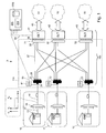
- FIG. 1 shows an optical access network 5 according to a first embodiment of the present invention.
- the optical access network 5 comprises a plurality of access sub-networks 10, 11, 12.
- Each access sub-network in Figure 1 is a WDM-PON 10, 11, 12.
- the optical access network 5 connects to multiple operator networks 51, 52, 53.
- Each WDM-PON 10, 11, 12 has a tree-like structure of fibres 14 emanating from a trunk fibre 16.
- Each WDM-PON 10, 11, 12 can be used as an access network to serve Optical Network Termination units (ONTs) 13.
- ONTs can be deployed at individual subscriber premises or at curbside cabinets, depending on the type of PON architecture. In an implementation where ONTs are deployed at curbside cabinets, electrical cables connect the ONT to terminals at subscriber premises.
- Each WDM-PON 10, 11, 12 can serve residential customers, commercial customers, wireless infrastructure (e.g. wireless base stations or access points), or any mix of these.
- the optical access network 5 comprises apparatus 41, 42, 43, 110 for interconnecting the wavelength division multiplexed passive optical networks (WDM-PON) 10, 11, 12 and operator networks 51, 52, 53.
- Apparatus 41, 42, 43, 110 can be installed at a Central Office (CO) 100 and, for clarity, Figure 1 shows this arrangement.
- CO Central Office
- the multiple wavelength division multiplexed passive optical networks (WDM-PON) 10, 11, 12 each connect with the CO 100.
- Central Office 100 interfaces with metro or core communication networks 51, 52, 53 belonging to different operators.
- the operators are different telco providers who can compete to offer a communications service to subscribers served by the WDM-PONs 10, 11, 12.
- CO 100 comprises apparatus for each operator who wishes to provide a communication service to any of the subscribers served by the WDM-PONs 10, 11, 12.
- OLT optical line termination unit
- each WDM-PON 10, 11, 12 a set of wavelength channels, called lambdas ⁇ , are allocated for communication between the Central Office 100 and ONTs 13.
- a single lambda is allocated for communication between the Central Office 100 and a single ONT 13.
- a set of wavelength channels are carried between the CO and a remote node 12 on a trunk fibre 16, and then passively demultiplexed at a remote node 15 onto a set of fibres 14.
- Each fibre 14 carries a single wavelength channel to an ONT 13.
- Network 5 supports communication in an upstream direction (i.e. from an ONT 13 towards an OLT 41, 42, 43) and in a downstream direction (i.e. from an OLT 41, 42, 43 towards an ONT 13).
- Bi-directional communication can be achieved in various ways, such as by the use of two wavelength channels to each ONT (i.e. one wavelength channel ⁇ D for downstream communication and a different wavelength channel ⁇ U for upstream communication) or by time-division multiplexed use of a single wavelength channel.
- CO side refers to the side of network apparatus nearest the operator networks 51, 52, 53 and the term “user side” refers to the side of network apparatus nearest the ONTs 13.
- Optical apparatus 110 which will be called wavelength routing apparatus 110, connects the WDM-PONs 10, 11, 12 and the OLTs 41, 42, 43.
- the wavelength routing apparatus 110 works in the upstream and downstream directions. In the upstream direction, the wavelength routing apparatus 110 routes wavelengths between the WDM-PONs 10, 11, 12 and the OLTs 41, 42, 43 so that a particular wavelength channel is connected between a WDM-PON and an OLT of a required operator network. In the downstream direction, the wavelength routing apparatus 110 routes wavelengths between the OLTs 41, 42, 43 and the WDM-PONs 10, 11, 12 so that a particular wavelength channel is connected between an OLT of a required operator network and an ONT.
- the wavelength routing apparatus 110 can separately route multiple wavelength channels of the same wavelength.
- OLT 41 can use a particular wavelength - say ⁇ 1 - for a wavelength channel between the OLT 41 and WDM-PON 10
- OLT 42 can use ⁇ 1 for a wavelength channel between the OLT 42 and WDM-PON 11
- OLT 43 can use ⁇ 1 for a wavelength channel between the OLT 43 and WDM-PON 12.
- it allows a particular OLT to use the same wavelength for a wavelength channel serving each of a plurality of different WDM-PONs 10, 11, 12.
- a wavelength - say ⁇ 2 - used for communication between OLT 41 and an ONT 13 in WDM-PON 10 can also be used for communication between OLT 41 and an ONT 13 in WDM-PON 11 and for communication between OLT 41 and an ONT 13 in WDM-PON 12. Separation is maintained between multiple instances of the same wavelength within the OLTs and wavelength routing apparatus 110, allowing each instance of the wavelength to carry different traffic.
- FIGS 1 , 3 and 4 show an advantageous form of the wavelength routing apparatus 110.
- Each trunk fibre 16 leading to a WDM-PON 10, 11, 12 connects to a respective splitter/combiner 21, 22, 23.
- Splitter/combiner 21 comprises a port 24 on the user side of the device for connecting to trunk fibre 16 and a set of ports 25 on the CO side of the device 21.
- splitter/combiner 21 functions as a splitter and replicates the set of signals ( ⁇ 1 - ⁇ N ) received on fibre 16 onto each of the ports 25 on the CO side of the splitter.
- splitter/combiner 21 functions as a combiner and combines the set of signals received on ports 25 and transmits the combined signal on port 24 on the user side of the splitter.
- a wavelength routing device 31, 32, 33 connects to the user side of a respective OLT 41, 42, 43.
- each wavelength routing device 31, 32, 33 is a cyclic arrayed waveguide grating (AWG) 31, 32, 33.
- AWG cyclic arrayed waveguide grating
- the cyclic AWG can be an N port x N port device, or other sized devices can be used.
- Each CO side port 35 connects to a port on the user side of OLT 41.
- Ports 34 on the user side of the cyclic AWG 31 connect, via fibres 27, to ports 25 on the splitters 21, 22, 23.
- the cyclic AWG 31 provides a wavelength multiplexing/demultiplexing function and a wavelength routing function.
- a set of wavelength signals ( ⁇ 1 - ⁇ N ) received on a user side port 34 are demultiplexed onto the set of CO side ports 35.
- a set of wavelength signals ( ⁇ 1 - ⁇ N ) received on the set of CO side ports 35 are multiplexed and output on one of the user side ports 34. Operation of the cyclic AWG is described in more detail later.
- a Cyclic AWG can carry a wavelength pair per port. One of the wavelengths in a wavelength pair is used for upstream communication and the other wavelength in a wavelength pair is used for downstream communication.
- the upstream and downstream wavelengths are located in different frequency bands.
- the range 1530nm - 1560nm can be used for downstream communication
- the range 1570nm - 1600nm can be used for upstream communication.
- the offset between a downstream wavelength and the corresponding upstream wavelength, on the same AWG port is 40nm.
- Table 1, shown later, can be considered to define one of the wavelengths in the wavelength pair.
- the other wavelength in the wavelength pair is found by adding a fixed wavelength offset to the value in Table 1.
- the wavelength routing apparatus shown in Figures 1 , 3 and 4 is passive and static.
- the term "static" means that the wavelength routing relationship between input ports of the cyclic AWG and output ports of the cyclic AWG, and between input ports of the cyclic AWG and output ports of the combiner, is static, and does not change.
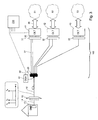
- FIG. 2 shows one of the optical line termination units (OLT) 41 of Figure 1 in more detail.
- the OLT 41 comprises a set of ports 35 which connect to a cyclic AWG 31.
- the OLT 41 comprises an interface 45 to a metro or core network of that operator.
- each port 35 carries a wavelength channel ⁇ U used for upstream communication and a separate wavelength channel ⁇ D used for downstream communication.
- unit 81 forwards the wavelengths used for upstream communication from ports 35 to a receiver unit 82.
- Each wavelength channel comprises an optical signal which is modulated in some way (e.g. by phase or amplitude/intensity modulation) with coded data.
- each upstream wavelength channel is demodulated by receiver unit 82.
- signals are received from interface 45 and an optical source 84 in transmitter unit 83 is modulated with the data signal to form a wavelength channel.
- a set of wavelength channels are combined by unit 81 and output from a port 35 of the OLT 41.
- Optical sources 84 can be fixed wavelength sources which are connected to a required port of the transmitter unit 83, such as by a manual or an automatic switching operation. More advantageously, optical sources 84 are tunable devices which can be caused to operate at a required wavelength.
- a tunable source 84 is associated with each port of the transmitter unit 83.
- a transceiver comprises a combination of a receiver device in receiver unit 82 and a transmitter device in transmitter unit 83.
- Control unit 90 controls operation of the optical sources 84.
- Control unit 90 interfaces 66 with a network management unit 200.
- Figure 2 shows one example form of the OLT 41 and it will be appreciated that it can take different forms.
- the OLT can be fully optical, with no electrical-to-optical conversion.
- the OLT can receive an optical signal from an operator network at a particular wavelength and either (i) forward it at the received wavelength or (ii) adjust the wavelength of the received optical signal to a wavelength required in the destination WDM-PON.
- Interface 45 can take various forms.
- Interface 45 can comprise functions such as an interface to a WDM or Dense Wavelength Division Multiplexed (DWDM) link used to connect to the operator network 51 and a switching function to switch signals between required channels of the OLT and required channels of the WDM/DWDM link.
- WDM Wideband Division Multiplexed
- any wavelength ( ⁇ 1 - ⁇ N ) from any one of the WDM-PONs 10, 11, 12 can connect, via a respective splitter 21, 22, 23, and a cyclic AWG 31, 32, 33, with an OLT 41, 42, 43 of a desired operator.
- ⁇ 1 a subscriber in WDM-PON 10 is allocated wavelength ⁇ 1 .
- This subscriber receives a communication service from operator network 53.
- Wavelength ⁇ 1 from WDM-PON 10 is split at splitter 21 onto a set of fibres 27.
- One of these fibres 27 connects with an input port of cyclic AWG 33.
- Wavelength ⁇ 1 travels through the cyclic AWG 33, and from an output port of the cyclic AWG 33 to OLT 43 of operator network 53.
- Any OLT 41, 42, 43 of an operator can connect to one, or more, of the WDM-PONs 10, 11, 12.
- any of the OLTs 41, 42, 43 of an operator can connect, via a respective cyclic AWG 31, 32, 33 and a splitter 21, 22, 23 with any one of the WDM-PONs 10, 11, 12.
- Two optical interfaces emitting at the same wavelength can coexist in the same OLT provided that they are sent to two different WDM-PONs 10, 11, 12.
- the cyclic AWG maintains separation of the wavelengths at the OLT itself. This property exists for upstream and downstream directions of communication.
- traffic on wavelength ⁇ 1 is received from OLT 41 on one of the ports 35 of AWG 31 and routed to an output port 34 of the AWG 31 which is connected to the splitter 21 connected to WDM-PON 10.
- (different) traffic on wavelength ⁇ 1 is received from OLT 41 on another of the ports 35 of AWG 31 and routed to an output port 34 of the AWG 31 which is connected to splitter 22 connected to WDM-PON 11.
- traffic on wavelength ⁇ 1 is received at port 24 of splitter 21 from WDM-PON 10 and forwarded to a port 34 of AWG 31.
- AWG 31 routes wavelength ⁇ 1 to a port 35, which is connected to a receiver in OLT 41 configured to receive traffic on this wavelength.
- (different) traffic on wavelength ⁇ 1 is received at a port 24 of splitter 22 from WDM-PON 11 and forwarded to another port 34 of AWG 31.
- AWG 31 routes wavelength ⁇ 1 to a port 35, which is connected to a receiver in OLT 41 configured to receive traffic on this wavelength.
- THis property of the wavelength routing apparatus 110 allows two or more of the WDM-PONs 10, 11, 12 to simultaneously use the same set of wavelengths ( ⁇ 1 - ⁇ N ), and for any of the OLTs 41, 42, 43 to serve multiple ONTs 13 in different WDM-PONs operating on the same wavelength.
- a further feature of the apparatus shown in Figure 1 is a monitoring arrangement for monitoring which wavelengths are in use in each of the WDM-PONs 10, 11, 12.
- a monitoring device 61 On the user side of each splitter 21, 22, 23 a small portion of the optical signal is tapped and coupled to a monitoring device 61.
- the monitoring device 61 connects 65 with a management unit 200.
- the monitoring device 61 can simply forward the optical signal tapped at the splitter 21, for analysis at unit 200 or, advantageously, it is an Optical Spectrum Analyser (OSA) for analysing which wavelengths are in use and forwarding a data signal to the management unit 200 indicating which wavelengths are in use.
- Management unit 200 also connects, via a respective path 66, with each of the OLT units 41, 42, 43.
- Management unit 200 controls configuration of the system. Management unit 200 determines, from the information received via paths 65, which wavelength channels are in use on each of the WDM-PONs 10, 11, 12. This information is held as a look-up table in store 220. Advantageously, this information is accessible by the OLTs 41, 42, 43 of different operator networks, thereby allowing the different operator networks to co-ordinate their use of wavelength channels. For example, if OLT 41 is already using wavelength ⁇ 1 to serve an ONT in WDM-PON 10, then other OLTs 42, 43 will not use this wavelength channel to serve an ONT in WDM-PON 10.
- the wavelength routing unit 110 shown in Figure 1 uses cyclic AWGs (e.g. NxN AWGs). It will now be described how a cyclic AWG operates.
- a cyclic AWG operates as a static wavelength router.
- a cyclic AWG is a device having a set of input ports and a set of output ports.
- An NxN cyclic AWG will be considered (N input ports, N output ports).
- a regular (non-cyclic) AWG when a comb of N wavelengths is applied at one input port, the wavelengths in the comb are split so that each wavelength of the comb is present at a corresponding output port.
- a configuration unit 210 performs the method.
- the configuration unit 210 can form part of the management unit 200, or can comprise a further functional unit of the access network 5.
- each OLT 41, 42, 43 can have a dedicated configuration unit 210.
- Each OLT 41, 42, 43 uses three different tables.
- a first table (Table 1 above) indicates what wavelength corresponds to each output port/input port pair of the NxN cyclic AWG. To explain this table, consider that a signal at wavelength ⁇ 2 is applied to input (CO side) port 2. The signal is emitted on output (user side) port 1. Similarly, if wavelength ⁇ 2 is received at output (user side) port 1 it will emerge on input (CO side) port 2.
- signals at the same wavelength ⁇ 2 can be applied to other input ports of the OLT and they are emitted on output ports according to Table 1. So, a signal ⁇ 2 applied to input (CO side) port 3 is emitted from output (user side) port 10 and a signal ⁇ 2 applied to input (CO side) port 4 is emitted from output (user side) port 9.
- a second table indicates what wavelengths are currently used at that OLT.
- Table 2 An example is shown below. where "x" indicates the wavelength indicated in column is already used on the WDM-PON corresponding to the AWG output port indicated in the column. In this example, the WDM-PON corresponding to output (user side) port 1 already uses the wavelengths ⁇ 1, ⁇ 3, ⁇ 6 and ⁇ 7.
- Table 2 can be populated using the wavelength monitoring function described earlier. Before allocating a wavelength, Table 2 is updated using the latest information 220 which has been obtained using the wavelength monitoring function. If operator networks share information about which wavelengths they have assigned in each WDM-PON, then this shared information can be used to populate Table 2, without needing to perform the wavelength monitoring function.
- a third table indicates what input (CO side) ports are already in use on the NxN cyclic AWG: where "x" indicates the input port is busy and cannot be used.
- the configuration module checks Table 2 for the available wavelengths on the WDM-PON connected to that port, which are ⁇ 2, ⁇ 4, ⁇ 5, ⁇ 8, ⁇ 9, ⁇ 10 in this example. The configuration module then selects one of these wavelengths, e.g. ⁇ 2. Using Table 1, the configuration module determines which input port corresponds to ⁇ 2 ⁇ on the output port 1. Stated another way, the configuration module determines which input (CO side) port a signal at ⁇ 2 must be applied to in order for it to emerge on output port 1 corresponding to the required WDM-PON. In this example, it is input port 2.
- the configuration module determines, using Table 2, if input port 2 is free. In this example it is free, so a transceiver can be connected to this input (CO side) port.
- the tables shown above can be held as data structures in a data store 220 at the management unit 200 or at some other data store which is accessible by the configuration unit 210. In this example the wavelength ⁇ 2 is selected. The tables are updated to indicate that ⁇ 2 is now in use. No other instance of ⁇ 2 can be used by the OLT to serve an ONT in the same WDM-PON. ⁇ 2 is marked as "in use" in Table 2 for output port 2, and for all other output ports which are connected to the same WDM-PON.
- the corresponding Table 2 held for other OLTs is updated to indicate that ⁇ 2 is "in use” on any output ports which connect to the WDM-PON where ⁇ 2 has just been allocated. This prevents other OLTs from allocating the same wavelength. ⁇ 2 can still be used by the OLT to serve an ONT in any another WDM-PON where ⁇ 2 is not already in use.
- FIG. 1 there are multiple WDM-PONs 10, 11, 12 and multiple AWGs 31, 32, 33 and OLTs 41, 42, 43 connecting to operator networks 51, 52, 53.
- Each passive splitter 21, 22, 23 is shown with a single link 27 to a cyclic AWG.
- Providing multiple links 27 allows a greater opportunity for routing a required wavelength between an OLT 41 and a WDM-PON 10. Referring again to the configuration example described above, consider that the WDM-PON is connected to output (user side) ports 1 and 2 of the cyclic AWG.
- An operator network 51 can connect to multiple OLT units to further increase capacity.
- the cyclic AWG will, by itself, prevent any more than one instance of a wavelength being output to a given WDM-PON. Referring to Table 1, only once instance of wavelength ⁇ 1 will be output to port 1.
- there are multiple links 27 between an OLT 31 and a splitter 21 serving a WDM-PON there is a possibility that multiple instances of a wavelength can be output to a given WDM-PON.
- Configuration module 210 will ensure that only one instance of the same wavelength is used in WDM-PON 10 by using the information held in Table 2.
- Other OLTs can also access Table 2 to ensure that only one instance of the same wavelength is used by any of the OLTs 41, 42, 43 in WDM-PON 10.
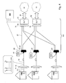
- Figure 3 shows an optical access network comprising a single WDM-PON and connections to multiple operator networks 51, 52, 53.
- the splitter 21 can comprise a single, or multiple, links 27 between splitter ports 25 and a particular one of the cyclic AWGs 31, 32, 33. Multiple links are shown between ports 25 and each of OLT 41 and OLT 42.
- Figure 3 typically represents an early stage of access network deployment. Additional WDM-PONs can be added to arrive at the arrangement shown in Figure 1 .
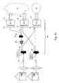
- Figure 4 shows another embodiment of an optical access network comprising multiple WDM-PONs and connections to multiple operator networks.
- the number of operator networks is less than the number of WDM-PONs.
- the splitter 21 can comprise a single, or multiple, links 27 between splitter ports 25 and a particular one of the cyclic AWGs 31, 32, 33.
- the number of splitter ports 25 should be large enough to enable one OLT to serve users belonging to different WDM-PONs.
- the limit case is when one operator serves N users, one user per WDM-PON, by means of the same OLT.
- FIG. 5 shows a general method of operating the apparatus of the access network.
- wavelength channels are received from OLTs. There can be one OLT or several OLTs.
- wavelength channels are routed to WDM-PONs using the wavelength routing apparatus 110. Different wavelength channels of the same wavelength value are routed to different ones of the WDM-PONs.
- Apparatus installed at the Central Office 100 can be modified as additional WDM-PONs are added to the access network.
- Apparatus installed at the Central Office 100 can be modified as additional operator networks are added.
- a new subscriber wishes to obtain service in the access network from a particular operator network (e.g. network 51).
- the subscriber will be served by one of the existing WDM-PONs 10, 11, 12.
- WDM-PON 10 Depending on the type of access network, a new ONT 13 is installed at the subscriber premises (FTTH), or cabling is installed between an existing ONT 13 in the WDM-PON and a new terminal in the subscriber premises (FTTC). No additional apparatus is required in the CO.
- Figure 6 describes the method.
- a request for service is received for a subscriber in one of the WDM-PONs.
- Step 212, 213 the configuration process described above is performed to find an available wavelength between the OLT 41 of operator network 51 and the new subscriber in WDM-PON 10.
- a transceiver in OLT 41 is connected to the input (CO side) port 35.
- Step 214 checks if there is a free input port. If a free input port is found at step 214, the method proceeds to step 216 and a transmitter operating at the available wavelength is connected to the input port. As described above, this can comprise manually, or automatically, forming a connection between a source operating at the required wavelength and the required input port 35 of the AWG, or by controlling a tunable source connected to the input port to operate at the required wavelength.
- step 214 If a free input port is not found at step 214, the method proceeds to step 215.
- a connection is not possible using the existing apparatus.
- An upgrade path may be used to provide service, as described later.
- the upstream path is configured at the same time. Typically, the upstream wavelength will be a fixed offset from the downstream wavelength.
- a receiver is connected to the AWG port.
- FIG. 7 describes the method.
- an OLT 43 is provided for the new operator.
- the OLT is connected to a free set of ports of the wavelength routing apparatus.
- the set of ports is created by installing an additional AWG 33 at the CO 100.
- wavelength channels are routed to the WDM-PONs.
- one or more links 27 are added between splitters 21, 22, 23 of the WDM-PONs 10, 11, 12 and the new AWG 33.
- the configuration process described above is performed to find available wavelengths to serve each of the ONTs in the WDM-PONs 10, 11, 12 which require service from the new operator network 53.
- a transceiver in OLT 43 is connected to the input (CO side) port 35.
- this can comprise a manual or automatic switch between a source operating at that wavelength and the required input port 35 of the AWG, or by controlling a tunable source connected to the input port to operate at the required wavelength.
- the upstream path is configured at the same time. Typically, the upstream wavelength will be a fixed offset from the downstream wavelength.
- a receiver is connected to the AWG port. Step 222 is repeated for each ONT requiring service by the new operator network.
- a new WDM-PON can be added to the access network.
- FIG 1 consider that WDM-PONs 10 and 11 already exist.
- Figure 8 describes the method for adding a new WDM-PON 12 to the access network.
- Apparatus for the new WDM-PON 12 is deployed at step 231. This comprises ONTs 13, fibres 14, a remote node 15 and trunk fibre 16 for the new WDM-PON.
- the trunk fibre is connected to a free port 24 on the wavelength routing apparatus 110.
- the port 24 is provided by adding a splitter 23 to the wavelength routing apparatus 110. Links 27 are added between splitter 23 and each of the AWGs 31, 32, 33.
- wavelength channels are configured and routed to the operator networks at step 233.
- the configuration process described above is performed to find available wavelengths to serve ONTs in the new WDM-PON 13.
- ONTs in the new WDM-PON 12 can be served by any of the operator networks 51, 52, 53.
- a transceiver in respective OLT 41, 42, 43 is connected to the input (CO side) port 35 of the AWG.
- the upstream path is configured at the same time.
- the upstream wavelength will be a fixed offset from the downstream wavelength.
- a receiver is connected to the AWG port. This is repeated for each ONT requiring service in the new WDM-PON.
- a request to transfer service is received.
- the configuration process described above is performed to determine if the current wavelength (e.g. ⁇ 1) that is used between the ONT 13 and OLT 41 can be used between the OLT 42 of the new operator network 52 and the subscriber in WDM-PON 10. This is because the operating wavelength of the ONT 13 is fixed at the deployment, when the ONT 13 is connected to a particular one of the ports 14 of the remote node 15. A change of the operating wavelength of the ONT would require a change at the remote node 15.
- Step 243 checks if there is a free input port. If a free input port is found at step 243, the method proceeds to step 244 and a transmitter in OLT 42, operating at the wavelength, is connected to the input port of AWG 32. The transceiver in OLT 41 is disconnected from the input (CO side) port 35 of AWG 31 and the tables held in store 220 are updated to reflect the new configuration. If a free input port is not found at step 243, the method proceeds to step 245. A connection is not possible using the existing apparatus. An upgrade path may be used to provide service, as described later. Typically, the upstream wavelength will be a fixed offset from the downstream wavelength. A receiver is connected to the same port of AWG 32.
- the configuration unit 210 determines which wavelengths are not already used on the WDM-PON and determines if, for at least one of these wavelengths, there is a free input (CO side) port of the AWG from where it is possible to send the wavelength to the corresponding output (user side) port. If the check is positive, the operator plugs an optical transceiver (e.g. a SFP) emitting at that wavelength on the AWG input (CO side) port. If the check is negative, the configuration module repeats until a free port is found on other OLTs owned by the operator. If no free port is found on any OLT of the operator, the apparatus of Figure 1 does not permit a connection.
- an optical transceiver e.g. a SFP
- Figure 10 shows an alternative apparatus which allows additional connections.
- An additional splitter 60 is added upstream of the 1:N splitter 21.
- this additional splitter 60 is a 1:2 splitter to minimise losses, although the splitter can split a signal a larger number of ways.
- One port 61 of the new splitter 60 is connected to the NxN AWG 31, as in the apparatus of Figures 1 to 3 .
- the other port 62 of splitter 60 is used for expansion. For example, it can be connected to an additional NxN cyclic AWG 131, with an associated OLT 141. It may be necessary to compensate for the additional insertion loss introduced by the splitter 60 by means of optical amplifiers 64.
- the wavelength routing apparatus 110 which routes wavelengths between WDM-PONs 10, 11, 12 and OLTs 41, 42, 43 of different operator networks can be co-located at a central office CO 100.
- the AWG of one operator network can be located at a different physical location from the AWG of another operator. This allows further flexibility.
- the OLTs 41, 42, 43 of different operators share configuration data 210, thereby still allowing the OLTs 41, 42, 43 of different operator networks to co-ordinate their use of wavelength channels.
Landscapes
- Engineering & Computer Science (AREA)
- Computer Networks & Wireless Communication (AREA)
- Signal Processing (AREA)
- Optical Communication System (AREA)
- Small-Scale Networks (AREA)
Claims (15)
- Vorrichtung zur Verwendung in einem optischen Zugangsnetz (5), wobei das Zugangsnetz L Wellenlängenmultiplexzugriffs-Subnetze (10, 11, 12), wobei L ≥ 2, umfasst, wobei jedes der Wellenlängenmultiplexzugriffs-Subnetze (10, 11, 12) so ausgelegt ist, dass es einen Satz von Wellenlängenkanälen (λ1 - λN) verwendet und eine optische Strecke (16) zum Übertragen eines Signals aufweist, das einen gemultiplexten Satz der Wellenlängenkanäle umfasst, wobei die Vorrichtung umfasst:M optische Leitungsanschlussvorrichtungen (41, 42, 43), wobei M ≥ 1, jeweils zum Empfangen von Verkehr von einem jeweiligen Betreibernetz (51, 52, 53) und zum Ausgeben von Verkehr auf den Wellenlängenkanälen;eine passive und statische Wellenlängenleitvorrichtung (110), die M Sätze von ersten Ports (35) und L zweite Ports (24) umfasst, jeder Satz von ersten Ports zum Verbinden mit einer jeweiligen der optischen Leitungsanschlussvorrichtungen (41, 42, 43) und jeder zweite Port (24) zum Verbinden mit einer optischen Strecke (16) eines jeweiligen der Wellenlängenmultiplexzugriffs-Subnetze, wobei die Wellenlängenleitvorrichtung (110) so ausgelegt ist, dass sie die Wellenlängenkanäle (λ1 - λN) zwischen den Sätzen von ersten Ports (35) und den zweiten Ports (24) leitet und verschiedene Wellenlängenkanäle der gleichen Wellenlänge zu verschiedenen der zweiten Ports (24) leitet.
- Vorrichtung nach Anspruch 1, wobei die Wellenlängenleitvorrichtung (110) so ausgelegt ist, dass sie verschiedene Wellenlängenkanäle der gleichen Wellenlänge, die von einer der optischen Leitungsanschlussvorrichtungen (41, 42, 43) empfangen werden, zu verschiedenen der zweiten Ports (24) leitet.
- Vorrichtung nach Anspruch 1, wobei die Wellenlängenleitvorrichtung (110) so ausgelegt ist, dass sie Wellenlängenkanäle (λ1 - λN), die an den zweiten Ports (24) empfangen werden, zu den Sätzen von ersten Ports (35) leitet.
- Vorrichtung nach einem der vorhergehenden Ansprüche, wobei die Wellenlängenleitvorrichtung (110) umfasst:L Verteiler/Kombinierer (21, 22, 23), jeweils verbunden mit einem jeweiligen der zweiten Ports (24), wobei jeder Verteiler/Kombinierer (21, 22, 23) eine Mehrzahl von dritten Ports (25) aufweist und so ausgelegt ist, dass er Signale, die an der Mehrzahl von dritten Ports (25) empfangen werden, am zweiten Port (24) kombiniert und ausgibt;M Wellenlängenleiteinrichtungen (31, 32, 33), jeweils verbunden mit einem jeweiligen der Sätze von ersten Ports (35) und außerdem aufweisend vierte Ports (34) und ausgelegt zum Leiten von Wellenlängenkanälen zwischen dem Satz von ersten Ports (35) und den vierten Ports (34) in Abhängigkeit von einer Wellenlänge des Wellenlängenkanals und davon, an welchem Port des Satzes von ersten Ports (35) der Wellenlängenkanal empfangen wird; undStrecken (27), die so ausgelegt sind, dass sie die vierten Ports (34) der Wellenlängenleiteinrichtungen mit den dritten Ports der L Verteiler/Kombinierer (21, 22, 23) verbinden.
- Vorrichtung nach Anspruch 4, ferner umfassend einen weiteren Verteiler/Kombinierer (60), der in einem Pfad zwischen den dritten Ports (25) eines der L Verteiler/Kombinierer (21, 22, 23) und einem vierten Port (34) einer der Wellenlängenleiteinrichtungen (31, 32, 33) angeschlossen ist, wobei der weitere Verteiler/Kombinierer (60) einen Port (62) zum Anschließen einer weiteren Wellenlängenleiteinrichtung (131) bereitstellt.
- Vorrichtung nach einem der vorhergehenden Ansprüche, ferner umfassend eine Steuerung (200) und einen Speicher zum Speichern von Informationen darüber, welche Wellenlängen für die Wellenlängenkanäle (λ1 - λN) in jedem der Wellenlängenmultiplexzugriffs-Subnetze (10, 11, 12) in Verwendung sind.
- Verfahren zum Betreiben einer Vorrichtung in einem optischen Zugangsnetz, das L Wellenlängenmultiplexzugriffs-Subnetze (10, 11, 12), wobei L ≥ 2, umfasst, wobei jedes der Wellenlängenmultiplexzugriffs-Subnetze (10, 11, 12) so ausgelegt ist, dass es einen Satz von Wellenlängenkanälen (λ1 - λN) verwendet, jedes Wellenlängenmultiplexzugriffs-Subnetz (10, 11, 12) eine optische Strecke (16) zum Übertragen eines Signals aufweist, das einen gemultiplexten Satz der Kanäle umfasst, die Vorrichtung M optische Leitungsanschlussvorrichtungen (41, 42, 43), wobei M ≥ 1, umfasst, die jeweils mit einem jeweiligen Betreibernetz (51, 52, 53) verbunden sind, wobei das Verfahren umfasst:Empfangen (201) von Verkehr auf Wellenlängenkanälen von einer der optischen Leitungsanschlussvorrichtungen (41, 42, 43);Verwenden einer passiven und statischen Wellenlängenleitvorrichtung zum derartigen Leiten (202) der Wellenlängenkanäle zu den Wellenlängenmultiplexzugriffs-Subnetzen (10, 11, 12), dass verschiedene Wellenlängenkanäle der gleichen Wellenlänge zu verschiedenen Wellenlängenmultiplexzugriffs-Subnetzen (10, 11, 12) geleitet werden.
- Verfahren nach Anspruch 7, wobei die Wellenlängenleitvorrichtung (110) so ausgelegt ist, dass sie verschiedene Wellenlängenkanäle der gleichen Wellenlänge, die von einer der optischen Leitungsanschlussvorrichtungen (41, 42, 43) empfangen werden, zu verschiedenen der zweiten Ports (24) leitet.
- Verfahren nach Anspruch 7 oder 8, ferner umfassend:Empfangen von Wellenlängenkanälen von den Wellenlängenmultiplexzugriffs-Subnetzen (10, 11, 12);Leiten der empfangenen Wellenlängenkanäle (λ1 - λN) zu den optischen Leitungsanschlussvorrichtungen (41, 42, 43).
- Verfahren nach einem der Ansprüche 7 bis 9, wobei der Schritt des Leitens (202) der Wellenlängenkanäle umfasst:Anlegen der Wellenlängenkanäle an eine Wellenlängenleiteinrichtung, welche Wellenlängenkanäle zwischen Ports der Einrichtung in Abhängigkeit von einer Wellenlänge des Wellenlängenkanals und davon leitet, an welchem Port der Einrichtung der Wellenlängenkanal empfangen wird; undWeitersenden von Ausgaben der Wellenlängenleiteinrichtung zu L Verteilern/Kombinieren, wobei ein Verteiler/Kombinierer mit jedem der L Wellenlängenmultiplexzugriffs-Subnetze (10, 11, 12) assoziiert ist,wobei das Verfahren ferner ein Kombinieren von Signalen, die an jedem Verteiler/Kombinierer empfangen werden, und Weitersenden des kombinierten Signals zu den jeweiligen Wellenlängenmultiplexzugriffs-Subnetzen (10, 11, 12) umfasst.
- Verfahren nach Anspruch 7, ferner umfassend ein Verbinden eines ersten der Betreibernetze mit einem neuen Teilnehmer in einem ersten der L Wellenlängenmultiplexzugriffs-Subnetze, wobei das Verfahren umfasst:Auswählen (212) eines Wellenlängenkanals für den neuen Teilnehmer;Veranlassen (216), dass ein Sender in der optischen Leitungsanschlussvorrichtung (41) des ersten Betreibernetzes auf dem Wellenlängenkanal sendet.
- Verfahren nach Anspruch 11, wobei die Vorrichtung eine Wellenlängenleitvorrichtung (110) umfasst, die L Verteiler/Kombinierer, die jeweils mit einem der Wellenlängenmultiplexzugriffs-Subnetze verbunden sind, und M Wellenlängenleiteinrichtungen (31, 32, 33) umfasst, die jeweils mit einer jeweiligen der optischen Leitungsanschlussvorrichtungen verbunden sind, wobei jede Wellenlängenleiteinrichtung (31, 32, 33) so ausgelegt ist, dass sie Wellenlängenkanäle zwischen Ports der Einrichtung in Abhängigkeit von einer Wellenlänge des Wellenlängenkanals und davon leitet, an welchem Port der Einrichtung der Wellenlängenkanal empfangen wird, und der Schritt des Auswählens eines Wellenlängenkanals für den neuen Teilnehmer umfasst:Bestimmen (212), welche Wellenlängen zur Verwendung im ersten Wellenlängenmultiplexzugriffs-Subnetz verfügbar sind;Bestimmen (213), ob ein verfügbarer Port (35) in der Wellenlängenleiteinrichtung vorhanden ist, der einen der verfügbaren Wellenlängenkanäle mit dem ersten Wellenlängenmultiplexzugriffs-Subnetz verbinden kann, und Veranlassen, wenn dies der Fall ist, dass ein Sender in der optischen Leitungsanschlussvorrichtung (41) auf dem Wellenlängenkanal sendet.
- Verfahren nach Anspruch 7, ferner umfassend ein Verbinden mit einem neuen Betreibernetz durch:Bereitstellen (221) einer zusätzlichen optischen Leitungsanschlussvorrichtung (41);Verbinden (221) der zusätzlichen optischen Leitungsanschlussvorrichtung (41) mit dem neuen Betreibernetz; undLeiten (222) für jedes der L Wellenlängenmultiplexzugriffs-Subnetze, mit welchen das neue Betreibernetz Verbindung benötigt, der Wellenlängenkanäle zu dem Wellenlängenmultiplexzugriffs-Subnetz (10, 11, 12).
- Verfahren nach Anspruch 7, ferner umfassend ein Verbinden eines neuen Wellenlängenmultiplexzugriffs-Subnetzes für das neue Wellenlängenmultiplexzugriffs-Subnetz durch:Verbinden (232) mit dem neuen Wellenlängenmultiplexzugriffs-Subnetz;Leiten (233) für jedes der Betreibernetze, mit welchen das neue Wellenlängenmultiplexzugriff-Subnetz Verbindung benötigt, der Wellenlängenkanäle zwischen dem neuen Wellenlängenmultiplexzugriffs-Subnetz und den Betreibernetzen.
- Verfahren nach Anspruch 7, ferner umfassend ein Übermitteln eines Teilnehmers unter Verwendung eines ersten Wellenlängenkanals in einem ersten der Wellenlängenmultiplexzugriffs-Subnetze von einem ersten der Betreibernetze (51) zu einem zweiten der Betreibernetze (52) durch:Bestimmen (242), ob der erste Wellenlängenkanal durch eine optische Leitungsanschlussvorrichtung (42) des zweiten Betreibernetzes (52) verwendet werden kann; undVeranlassen (244), wenn der erste Wellenlängenkanal durch eine optische Leitungsanschlussvorrichtung (42) des zweiten Betreibernetzes (52) verwendet werden kann, dass ein Sender in der optischen Leitungsanschlussvorrichtung (42) des zweiten Betreibernetzes auf dem Wellenlängenkanal sendet.
Applications Claiming Priority (1)
| Application Number | Priority Date | Filing Date | Title |
|---|---|---|---|
| PCT/EP2010/055723 WO2011134507A1 (en) | 2010-04-28 | 2010-04-28 | Optical access network |
Publications (3)
| Publication Number | Publication Date |
|---|---|
| EP2564531A1 EP2564531A1 (de) | 2013-03-06 |
| EP2564531B1 true EP2564531B1 (de) | 2013-12-25 |
| EP2564531B2 EP2564531B2 (de) | 2017-03-01 |
Family
ID=43446717
Family Applications (1)
| Application Number | Title | Priority Date | Filing Date |
|---|---|---|---|
| EP10721137.7A Not-in-force EP2564531B2 (de) | 2010-04-28 | 2010-04-28 | Optisches zugangsnetz |
Country Status (3)
| Country | Link |
|---|---|
| US (1) | US8861957B2 (de) |
| EP (1) | EP2564531B2 (de) |
| WO (1) | WO2011134507A1 (de) |
Cited By (1)
| Publication number | Priority date | Publication date | Assignee | Title |
|---|---|---|---|---|
| US10615901B2 (en) | 2017-06-30 | 2020-04-07 | Juniper Networks, Inc. | Apparatus, systems, and methods for optical channel management |
Families Citing this family (18)
| Publication number | Priority date | Publication date | Assignee | Title |
|---|---|---|---|---|
| US9031408B2 (en) * | 2011-06-09 | 2015-05-12 | Telefonaktiebolaget L M Ericsson (Publ) | Method for fast wavelength division multiplexing (WDM) passive optical network (PON) initialization in heterogeneous networks |
| US8855492B2 (en) * | 2012-01-18 | 2014-10-07 | Telefonaktiebolaget Lm Ericsson (Publ) | Selectable multiple-wavelength access for optical network units in arrayed waveguide based wavelength division multiplexing passive optical network |
| US9377921B2 (en) * | 2012-06-29 | 2016-06-28 | Infinera Corporation | Digital link viewer |
| EP2913947B1 (de) * | 2014-02-27 | 2019-11-27 | ADVA Optical Networking SE | Passives optisches Netzwerk und optisches Leitungsendgerät |
| WO2016122527A1 (en) * | 2015-01-29 | 2016-08-04 | Hewlett Packard Enterprise Development Lp | Photonic interconnect including a cyclic arrayed waveguide grating |
| EP3113397A1 (de) * | 2015-06-29 | 2017-01-04 | Alcatel Lucent | Schutz eines optischen verteilungsnetzwerks |
| KR102459683B1 (ko) * | 2015-07-09 | 2022-10-28 | 삼성전자주식회사 | 무선 주파수 모듈에서의 교정장치 및 방법 |
| US9729950B2 (en) * | 2015-11-25 | 2017-08-08 | Google Inc. | Upgrading PON systems using a multi-cycle field AWG |
| WO2017150277A1 (ja) * | 2016-02-29 | 2017-09-08 | 日本電気株式会社 | 光伝送装置 |
| US20200052790A1 (en) * | 2017-03-22 | 2020-02-13 | Sumitomo Electric Industries, Ltd. | Upper device, opposing device, communication system, and communication method |
| US10616056B2 (en) | 2018-03-26 | 2020-04-07 | At&T Intellectual Property I, L.P. | Modulation and demodulation of signals conveyed by electromagnetic waves and methods thereof |
| US10547545B2 (en) | 2018-03-30 | 2020-01-28 | At&T Intellectual Property I, L.P. | Method and apparatus for switching of data channels provided in electromagnetic waves |
| CN111355554B (zh) * | 2018-12-20 | 2023-04-28 | 中兴通讯股份有限公司 | 路由合波器、路由合波方法、波分路由方法及网络系统 |
| CN112398569A (zh) * | 2019-08-15 | 2021-02-23 | 裴璇 | 一种支持wdm-pon子网间光互联的光接入系统与方法 |
| US20210119787A1 (en) | 2019-10-17 | 2021-04-22 | Cable Television Laboratories, Inc. | Quantum key distribution and management in passive optical networks |
| US10930992B1 (en) | 2019-12-03 | 2021-02-23 | At&T Intellectual Property I, L.P. | Method and apparatus for communicating between waveguide systems |
| US10812291B1 (en) | 2019-12-03 | 2020-10-20 | At&T Intellectual Property I, L.P. | Method and apparatus for communicating between a waveguide system and a base station device |
| DE102020104699B4 (de) | 2020-02-21 | 2024-07-25 | Deutsche Telekom Ag | Verfahren zur automatisierten Inbetriebnahme für Fiber-to-the-Home (FTTH) Endgeräte |
Family Cites Families (10)
| Publication number | Priority date | Publication date | Assignee | Title |
|---|---|---|---|---|
| KR100610245B1 (ko) * | 2004-11-16 | 2006-08-09 | 한국과학기술원 | 파장분할다중방식 수동형 광가입자망의 통신 복구시스템 |
| KR100724936B1 (ko) * | 2005-01-27 | 2007-06-04 | 삼성전자주식회사 | 자기 치유 수동형 광가입자망 |
| EP1761103B1 (de) | 2005-09-01 | 2011-07-06 | Lucent Technologies Nederland B.V. | Blockierungsfreie, zyklische wellenleitergittern-basierte Knotenarchitektur |
| CN101213776A (zh) * | 2006-01-27 | 2008-07-02 | 日本电信电话株式会社 | 光波长多路接入系统 |
| US8090256B2 (en) * | 2006-10-04 | 2012-01-03 | Arizona Board Of Regents, A Body Corporate Of The State Of Arizona, Acting For And On Behalf Of Arizona State University | Optical network architectures and optical communication schemes |
| US7970281B2 (en) * | 2007-01-26 | 2011-06-28 | Fujitsu Limited | System and method for managing different transmission architectures in a passive optical network |
| CN101290213B (zh) * | 2007-04-20 | 2011-12-21 | 华为技术有限公司 | 光纤长度测量方法、通信设备、通信系统 |
| US20090263122A1 (en) * | 2008-04-22 | 2009-10-22 | Roger Jonathan Helkey | Method and apparatus for network diagnostics in a passive optical network |
| US20110026930A1 (en) * | 2009-07-29 | 2011-02-03 | Zhi Cui | Methods and apparatus to upgrade communication services in subscriber distribution areas |
| US8412044B2 (en) * | 2009-07-31 | 2013-04-02 | Go! Foton Holdings, Inc. | Optical fiber network with improved fiber utilization |
-
2010
- 2010-04-28 WO PCT/EP2010/055723 patent/WO2011134507A1/en active Application Filing
- 2010-04-28 US US13/695,007 patent/US8861957B2/en active Active
- 2010-04-28 EP EP10721137.7A patent/EP2564531B2/de not_active Not-in-force
Cited By (2)
| Publication number | Priority date | Publication date | Assignee | Title |
|---|---|---|---|---|
| US10615901B2 (en) | 2017-06-30 | 2020-04-07 | Juniper Networks, Inc. | Apparatus, systems, and methods for optical channel management |
| US11595146B2 (en) | 2017-06-30 | 2023-02-28 | Juniper Networks, Inc. | Apparatus, systems, and methods for optical channel management |
Also Published As
| Publication number | Publication date |
|---|---|
| US8861957B2 (en) | 2014-10-14 |
| WO2011134507A1 (en) | 2011-11-03 |
| EP2564531B2 (de) | 2017-03-01 |
| US20130136447A1 (en) | 2013-05-30 |
| EP2564531A1 (de) | 2013-03-06 |
Similar Documents
| Publication | Publication Date | Title |
|---|---|---|
| EP2564531B1 (de) | Optisches zugangsnetz | |
| EP3169010B1 (de) | Twdm-passivnetzwerk mit erweiterter reichweite und kapazität | |
| EP1863204B1 (de) | System und Verfahren zum Übertragen von Verkehrsdaten in mehreren passiven optischen Netzwerken | |
| US7483633B2 (en) | Optical communication network | |
| CN102106103B (zh) | 光网络 | |
| US20160365931A1 (en) | Remote node configuration for providing upgraded services in a passive optical network and a passive optical network having the same | |
| US20070092249A1 (en) | System and Method for Traffic Distribution in an Optical Network | |
| US20050175344A1 (en) | System and apparatus for a carrier class WDM PON accommodating multiple services or protocols | |
| KR20140027502A (ko) | 이동 가능한 파장 분할 멀티플랙싱 수동 광 네트워크 | |
| GB2452180A (en) | Optical access network system | |
| US8335432B1 (en) | Extended broadband passive optical networks | |
| WO2010009533A1 (en) | Wdm pon rf/video broadcast overlay | |
| KR20140088438A (ko) | 파장 가변 광 모듈 기반 수동형 광 망 거리 확장장치 및 그 방법 | |
| JPWO2007026749A1 (ja) | 光通信ネットワークシステム、親局光通信装置および子局光通信装置 | |
| JP2013506329A (ja) | パッシブ光ネットワークの装置および方法 | |
| JP2001358697A (ja) | 光アクセス網、光網終端装置及び光加入者線終端装置 | |
| US20170150243A1 (en) | Upgrading PON Systems Using A Multi-Cycle Field AWG | |
| CN102064904B (zh) | 多业务共享光分配网络的业务传输方法、系统和装置 | |
| CN101073211A (zh) | 容纳多个服务或协议的运营商级wdm pon的系统和装置 | |
| JP2019068198A (ja) | 局側装置及び光アクセスネットワーク。 | |
| KR20110050413A (ko) | 파장 분할 다중 방식의 광가입자망 장치 | |
| JP2011014960A (ja) | 加入者側終端装置、局側終端装置、及び光通信システム | |
| WO2011154048A1 (en) | Optical access network |
Legal Events
| Date | Code | Title | Description |
|---|---|---|---|
| PUAI | Public reference made under article 153(3) epc to a published international application that has entered the european phase |
Free format text: ORIGINAL CODE: 0009012 |
|
| 17P | Request for examination filed |
Effective date: 20121010 |
|
| AK | Designated contracting states |
Kind code of ref document: A1 Designated state(s): AT BE BG CH CY CZ DE DK EE ES FI FR GB GR HR HU IE IS IT LI LT LU LV MC MK MT NL NO PL PT RO SE SI SK SM TR |
|
| RIN1 | Information on inventor provided before grant (corrected) |
Inventor name: D'ERRICO, ANTONIO Inventor name: GROSSO, RENATO Inventor name: GIORGI, LUCA Inventor name: CAVALIERE, FABIO |
|
| DAX | Request for extension of the european patent (deleted) | ||
| GRAP | Despatch of communication of intention to grant a patent |
Free format text: ORIGINAL CODE: EPIDOSNIGR1 |
|
| INTG | Intention to grant announced |
Effective date: 20130927 |
|
| RAP1 | Party data changed (applicant data changed or rights of an application transferred) |
Owner name: TELEFONAKTIEBOLAGET L M ERICSSON (PUBL) |
|
| GRAS | Grant fee paid |
Free format text: ORIGINAL CODE: EPIDOSNIGR3 |
|
| GRAA | (expected) grant |
Free format text: ORIGINAL CODE: 0009210 |
|
| AK | Designated contracting states |
Kind code of ref document: B1 Designated state(s): AT BE BG CH CY CZ DE DK EE ES FI FR GB GR HR HU IE IS IT LI LT LU LV MC MK MT NL NO PL PT RO SE SI SK SM TR |
|
| REG | Reference to a national code |
Ref country code: GB Ref legal event code: FG4D |
|
| REG | Reference to a national code |
Ref country code: CH Ref legal event code: EP |
|
| REG | Reference to a national code |
Ref country code: AT Ref legal event code: REF Ref document number: 647076 Country of ref document: AT Kind code of ref document: T Effective date: 20140115 |
|
| REG | Reference to a national code |
Ref country code: IE Ref legal event code: FG4D |
|
| REG | Reference to a national code |
Ref country code: DE Ref legal event code: R096 Ref document number: 602010012675 Country of ref document: DE Effective date: 20140213 |
|
| REG | Reference to a national code |
Ref country code: NL Ref legal event code: T3 |
|
| PG25 | Lapsed in a contracting state [announced via postgrant information from national office to epo] |
Ref country code: FI Free format text: LAPSE BECAUSE OF FAILURE TO SUBMIT A TRANSLATION OF THE DESCRIPTION OR TO PAY THE FEE WITHIN THE PRESCRIBED TIME-LIMIT Effective date: 20131225 Ref country code: LT Free format text: LAPSE BECAUSE OF FAILURE TO SUBMIT A TRANSLATION OF THE DESCRIPTION OR TO PAY THE FEE WITHIN THE PRESCRIBED TIME-LIMIT Effective date: 20131225 Ref country code: HR Free format text: LAPSE BECAUSE OF FAILURE TO SUBMIT A TRANSLATION OF THE DESCRIPTION OR TO PAY THE FEE WITHIN THE PRESCRIBED TIME-LIMIT Effective date: 20131225 Ref country code: NO Free format text: LAPSE BECAUSE OF FAILURE TO SUBMIT A TRANSLATION OF THE DESCRIPTION OR TO PAY THE FEE WITHIN THE PRESCRIBED TIME-LIMIT Effective date: 20140325 Ref country code: SE Free format text: LAPSE BECAUSE OF FAILURE TO SUBMIT A TRANSLATION OF THE DESCRIPTION OR TO PAY THE FEE WITHIN THE PRESCRIBED TIME-LIMIT Effective date: 20131225 |
|
| REG | Reference to a national code |
Ref country code: AT Ref legal event code: MK05 Ref document number: 647076 Country of ref document: AT Kind code of ref document: T Effective date: 20131225 |
|
| REG | Reference to a national code |
Ref country code: LT Ref legal event code: MG4D |
|
| PG25 | Lapsed in a contracting state [announced via postgrant information from national office to epo] |
Ref country code: LV Free format text: LAPSE BECAUSE OF FAILURE TO SUBMIT A TRANSLATION OF THE DESCRIPTION OR TO PAY THE FEE WITHIN THE PRESCRIBED TIME-LIMIT Effective date: 20131225 |
|
| PG25 | Lapsed in a contracting state [announced via postgrant information from national office to epo] |
Ref country code: BE Free format text: LAPSE BECAUSE OF FAILURE TO SUBMIT A TRANSLATION OF THE DESCRIPTION OR TO PAY THE FEE WITHIN THE PRESCRIBED TIME-LIMIT Effective date: 20131225 Ref country code: IS Free format text: LAPSE BECAUSE OF FAILURE TO SUBMIT A TRANSLATION OF THE DESCRIPTION OR TO PAY THE FEE WITHIN THE PRESCRIBED TIME-LIMIT Effective date: 20140425 Ref country code: EE Free format text: LAPSE BECAUSE OF FAILURE TO SUBMIT A TRANSLATION OF THE DESCRIPTION OR TO PAY THE FEE WITHIN THE PRESCRIBED TIME-LIMIT Effective date: 20131225 |
|
| PG25 | Lapsed in a contracting state [announced via postgrant information from national office to epo] |
Ref country code: SK Free format text: LAPSE BECAUSE OF FAILURE TO SUBMIT A TRANSLATION OF THE DESCRIPTION OR TO PAY THE FEE WITHIN THE PRESCRIBED TIME-LIMIT Effective date: 20131225 Ref country code: ES Free format text: LAPSE BECAUSE OF FAILURE TO SUBMIT A TRANSLATION OF THE DESCRIPTION OR TO PAY THE FEE WITHIN THE PRESCRIBED TIME-LIMIT Effective date: 20131225 Ref country code: CZ Free format text: LAPSE BECAUSE OF FAILURE TO SUBMIT A TRANSLATION OF THE DESCRIPTION OR TO PAY THE FEE WITHIN THE PRESCRIBED TIME-LIMIT Effective date: 20131225 Ref country code: CY Free format text: LAPSE BECAUSE OF FAILURE TO SUBMIT A TRANSLATION OF THE DESCRIPTION OR TO PAY THE FEE WITHIN THE PRESCRIBED TIME-LIMIT Effective date: 20131225 Ref country code: AT Free format text: LAPSE BECAUSE OF FAILURE TO SUBMIT A TRANSLATION OF THE DESCRIPTION OR TO PAY THE FEE WITHIN THE PRESCRIBED TIME-LIMIT Effective date: 20131225 Ref country code: RO Free format text: LAPSE BECAUSE OF FAILURE TO SUBMIT A TRANSLATION OF THE DESCRIPTION OR TO PAY THE FEE WITHIN THE PRESCRIBED TIME-LIMIT Effective date: 20131225 Ref country code: PT Free format text: LAPSE BECAUSE OF FAILURE TO SUBMIT A TRANSLATION OF THE DESCRIPTION OR TO PAY THE FEE WITHIN THE PRESCRIBED TIME-LIMIT Effective date: 20140428 |
|
| REG | Reference to a national code |
Ref country code: DE Ref legal event code: R026 Ref document number: 602010012675 Country of ref document: DE |
|
| PLBI | Opposition filed |
Free format text: ORIGINAL CODE: 0009260 |
|
| PLAX | Notice of opposition and request to file observation + time limit sent |
Free format text: ORIGINAL CODE: EPIDOSNOBS2 |
|
| PG25 | Lapsed in a contracting state [announced via postgrant information from national office to epo] |
Ref country code: DK Free format text: LAPSE BECAUSE OF FAILURE TO SUBMIT A TRANSLATION OF THE DESCRIPTION OR TO PAY THE FEE WITHIN THE PRESCRIBED TIME-LIMIT Effective date: 20131225 |
|
| 26 | Opposition filed |
Opponent name: HUAWEI TECHNOLOGIES CO., LTD. Effective date: 20140925 |
|
| PG25 | Lapsed in a contracting state [announced via postgrant information from national office to epo] |
Ref country code: MC Free format text: LAPSE BECAUSE OF FAILURE TO SUBMIT A TRANSLATION OF THE DESCRIPTION OR TO PAY THE FEE WITHIN THE PRESCRIBED TIME-LIMIT Effective date: 20131225 Ref country code: LU Free format text: LAPSE BECAUSE OF FAILURE TO SUBMIT A TRANSLATION OF THE DESCRIPTION OR TO PAY THE FEE WITHIN THE PRESCRIBED TIME-LIMIT Effective date: 20140428 Ref country code: PL Free format text: LAPSE BECAUSE OF FAILURE TO SUBMIT A TRANSLATION OF THE DESCRIPTION OR TO PAY THE FEE WITHIN THE PRESCRIBED TIME-LIMIT Effective date: 20131225 |
|
| REG | Reference to a national code |
Ref country code: CH Ref legal event code: PL |
|
| REG | Reference to a national code |
Ref country code: DE Ref legal event code: R026 Ref document number: 602010012675 Country of ref document: DE Effective date: 20140925 |
|
| REG | Reference to a national code |
Ref country code: FR Ref legal event code: ST Effective date: 20141231 |
|
| REG | Reference to a national code |
Ref country code: IE Ref legal event code: MM4A |
|
| PG25 | Lapsed in a contracting state [announced via postgrant information from national office to epo] |
Ref country code: LI Free format text: LAPSE BECAUSE OF NON-PAYMENT OF DUE FEES Effective date: 20140430 Ref country code: CH Free format text: LAPSE BECAUSE OF NON-PAYMENT OF DUE FEES Effective date: 20140430 |
|
| PG25 | Lapsed in a contracting state [announced via postgrant information from national office to epo] |
Ref country code: FR Free format text: LAPSE BECAUSE OF NON-PAYMENT OF DUE FEES Effective date: 20140430 |
|
| PLBB | Reply of patent proprietor to notice(s) of opposition received |
Free format text: ORIGINAL CODE: EPIDOSNOBS3 |
|
| PG25 | Lapsed in a contracting state [announced via postgrant information from national office to epo] |
Ref country code: IE Free format text: LAPSE BECAUSE OF NON-PAYMENT OF DUE FEES Effective date: 20140428 |
|
| PG25 | Lapsed in a contracting state [announced via postgrant information from national office to epo] |
Ref country code: SI Free format text: LAPSE BECAUSE OF FAILURE TO SUBMIT A TRANSLATION OF THE DESCRIPTION OR TO PAY THE FEE WITHIN THE PRESCRIBED TIME-LIMIT Effective date: 20131225 |
|
| PG25 | Lapsed in a contracting state [announced via postgrant information from national office to epo] |
Ref country code: MT Free format text: LAPSE BECAUSE OF FAILURE TO SUBMIT A TRANSLATION OF THE DESCRIPTION OR TO PAY THE FEE WITHIN THE PRESCRIBED TIME-LIMIT Effective date: 20131225 |
|
| PG25 | Lapsed in a contracting state [announced via postgrant information from national office to epo] |
Ref country code: SM Free format text: LAPSE BECAUSE OF FAILURE TO SUBMIT A TRANSLATION OF THE DESCRIPTION OR TO PAY THE FEE WITHIN THE PRESCRIBED TIME-LIMIT Effective date: 20131225 |
|
| PG25 | Lapsed in a contracting state [announced via postgrant information from national office to epo] |
Ref country code: BG Free format text: LAPSE BECAUSE OF FAILURE TO SUBMIT A TRANSLATION OF THE DESCRIPTION OR TO PAY THE FEE WITHIN THE PRESCRIBED TIME-LIMIT Effective date: 20131225 Ref country code: IT Free format text: LAPSE BECAUSE OF FAILURE TO SUBMIT A TRANSLATION OF THE DESCRIPTION OR TO PAY THE FEE WITHIN THE PRESCRIBED TIME-LIMIT Effective date: 20131225 Ref country code: GR Free format text: LAPSE BECAUSE OF FAILURE TO SUBMIT A TRANSLATION OF THE DESCRIPTION OR TO PAY THE FEE WITHIN THE PRESCRIBED TIME-LIMIT Effective date: 20140326 |
|
| PG25 | Lapsed in a contracting state [announced via postgrant information from national office to epo] |
Ref country code: TR Free format text: LAPSE BECAUSE OF FAILURE TO SUBMIT A TRANSLATION OF THE DESCRIPTION OR TO PAY THE FEE WITHIN THE PRESCRIBED TIME-LIMIT Effective date: 20131225 Ref country code: HU Free format text: LAPSE BECAUSE OF FAILURE TO SUBMIT A TRANSLATION OF THE DESCRIPTION OR TO PAY THE FEE WITHIN THE PRESCRIBED TIME-LIMIT; INVALID AB INITIO Effective date: 20100428 |
|
| PLBP | Opposition withdrawn |
Free format text: ORIGINAL CODE: 0009264 |
|
| PUAH | Patent maintained in amended form |
Free format text: ORIGINAL CODE: 0009272 |
|
| STAA | Information on the status of an ep patent application or granted ep patent |
Free format text: STATUS: PATENT MAINTAINED AS AMENDED |
|
| 27A | Patent maintained in amended form |
Effective date: 20170301 |
|
| AK | Designated contracting states |
Kind code of ref document: B2 Designated state(s): AT BE BG CH CY CZ DE DK EE ES FI FR GB GR HR HU IE IS IT LI LT LU LV MC MK MT NL NO PL PT RO SE SI SK SM TR |
|
| REG | Reference to a national code |
Ref country code: DE Ref legal event code: R102 Ref document number: 602010012675 Country of ref document: DE |
|
| REG | Reference to a national code |
Ref country code: NL Ref legal event code: FP |
|
| PG25 | Lapsed in a contracting state [announced via postgrant information from national office to epo] |
Ref country code: MK Free format text: LAPSE BECAUSE OF FAILURE TO SUBMIT A TRANSLATION OF THE DESCRIPTION OR TO PAY THE FEE WITHIN THE PRESCRIBED TIME-LIMIT Effective date: 20131225 |
|
| PGFP | Annual fee paid to national office [announced via postgrant information from national office to epo] |
Ref country code: NL Payment date: 20220426 Year of fee payment: 13 |
|
| PGFP | Annual fee paid to national office [announced via postgrant information from national office to epo] |
Ref country code: GB Payment date: 20220427 Year of fee payment: 13 Ref country code: DE Payment date: 20220427 Year of fee payment: 13 |
|
| REG | Reference to a national code |
Ref country code: DE Ref legal event code: R119 Ref document number: 602010012675 Country of ref document: DE |
|
| REG | Reference to a national code |
Ref country code: NL Ref legal event code: MM Effective date: 20230501 |
|
| GBPC | Gb: european patent ceased through non-payment of renewal fee |
Effective date: 20230428 |
|
| PG25 | Lapsed in a contracting state [announced via postgrant information from national office to epo] |
Ref country code: GB Free format text: LAPSE BECAUSE OF NON-PAYMENT OF DUE FEES Effective date: 20230428 |
|
| PG25 | Lapsed in a contracting state [announced via postgrant information from national office to epo] |
Ref country code: NL Free format text: LAPSE BECAUSE OF NON-PAYMENT OF DUE FEES Effective date: 20230501 Ref country code: GB Free format text: LAPSE BECAUSE OF NON-PAYMENT OF DUE FEES Effective date: 20230428 Ref country code: DE Free format text: LAPSE BECAUSE OF NON-PAYMENT OF DUE FEES Effective date: 20231103 |