EP2564064B1 - Moteur a effet hall avec regulation de la temperature du dispositif de chauffage de la cathode - Google Patents
Moteur a effet hall avec regulation de la temperature du dispositif de chauffage de la cathode Download PDFInfo
- Publication number
- EP2564064B1 EP2564064B1 EP11723536.6A EP11723536A EP2564064B1 EP 2564064 B1 EP2564064 B1 EP 2564064B1 EP 11723536 A EP11723536 A EP 11723536A EP 2564064 B1 EP2564064 B1 EP 2564064B1
- Authority
- EP
- European Patent Office
- Prior art keywords
- cathode
- discharge current
- temperature
- magnitude
- thruster
- Prior art date
- Legal status (The legal status is an assumption and is not a legal conclusion. Google has not performed a legal analysis and makes no representation as to the accuracy of the status listed.)
- Active
Links
Images

Classifications
-
- H—ELECTRICITY
- H05—ELECTRIC TECHNIQUES NOT OTHERWISE PROVIDED FOR
- H05H—PLASMA TECHNIQUE; PRODUCTION OF ACCELERATED ELECTRICALLY-CHARGED PARTICLES OR OF NEUTRONS; PRODUCTION OR ACCELERATION OF NEUTRAL MOLECULAR OR ATOMIC BEAMS
- H05H1/00—Generating plasma; Handling plasma
- H05H1/54—Plasma accelerators
-
- F—MECHANICAL ENGINEERING; LIGHTING; HEATING; WEAPONS; BLASTING
- F03—MACHINES OR ENGINES FOR LIQUIDS; WIND, SPRING, OR WEIGHT MOTORS; PRODUCING MECHANICAL POWER OR A REACTIVE PROPULSIVE THRUST, NOT OTHERWISE PROVIDED FOR
- F03H—PRODUCING A REACTIVE PROPULSIVE THRUST, NOT OTHERWISE PROVIDED FOR
- F03H99/00—Subject matter not provided for in other groups of this subclass
-
- F—MECHANICAL ENGINEERING; LIGHTING; HEATING; WEAPONS; BLASTING
- F03—MACHINES OR ENGINES FOR LIQUIDS; WIND, SPRING, OR WEIGHT MOTORS; PRODUCING MECHANICAL POWER OR A REACTIVE PROPULSIVE THRUST, NOT OTHERWISE PROVIDED FOR
- F03H—PRODUCING A REACTIVE PROPULSIVE THRUST, NOT OTHERWISE PROVIDED FOR
- F03H1/00—Using plasma to produce a reactive propulsive thrust
- F03H1/0006—Details applicable to different types of plasma thrusters
- F03H1/0031—Thermal management, heating or cooling parts of the thruster
-
- F—MECHANICAL ENGINEERING; LIGHTING; HEATING; WEAPONS; BLASTING
- F03—MACHINES OR ENGINES FOR LIQUIDS; WIND, SPRING, OR WEIGHT MOTORS; PRODUCING MECHANICAL POWER OR A REACTIVE PROPULSIVE THRUST, NOT OTHERWISE PROVIDED FOR
- F03H—PRODUCING A REACTIVE PROPULSIVE THRUST, NOT OTHERWISE PROVIDED FOR
- F03H1/00—Using plasma to produce a reactive propulsive thrust
- F03H1/0037—Electrostatic ion thrusters
-
- F—MECHANICAL ENGINEERING; LIGHTING; HEATING; WEAPONS; BLASTING
- F03—MACHINES OR ENGINES FOR LIQUIDS; WIND, SPRING, OR WEIGHT MOTORS; PRODUCING MECHANICAL POWER OR A REACTIVE PROPULSIVE THRUST, NOT OTHERWISE PROVIDED FOR
- F03H—PRODUCING A REACTIVE PROPULSIVE THRUST, NOT OTHERWISE PROVIDED FOR
- F03H1/00—Using plasma to produce a reactive propulsive thrust
- F03H1/0037—Electrostatic ion thrusters
- F03H1/0062—Electrostatic ion thrusters grid-less with an applied magnetic field
-
- F—MECHANICAL ENGINEERING; LIGHTING; HEATING; WEAPONS; BLASTING
- F03—MACHINES OR ENGINES FOR LIQUIDS; WIND, SPRING, OR WEIGHT MOTORS; PRODUCING MECHANICAL POWER OR A REACTIVE PROPULSIVE THRUST, NOT OTHERWISE PROVIDED FOR
- F03H—PRODUCING A REACTIVE PROPULSIVE THRUST, NOT OTHERWISE PROVIDED FOR
- F03H1/00—Using plasma to produce a reactive propulsive thrust
- F03H1/0037—Electrostatic ion thrusters
- F03H1/0062—Electrostatic ion thrusters grid-less with an applied magnetic field
- F03H1/0068—Electrostatic ion thrusters grid-less with an applied magnetic field with a central channel, e.g. end-Hall type
-
- G—PHYSICS
- G05—CONTROLLING; REGULATING
- G05D—SYSTEMS FOR CONTROLLING OR REGULATING NON-ELECTRIC VARIABLES
- G05D23/00—Control of temperature
- G05D23/19—Control of temperature characterised by the use of electric means
- G05D23/20—Control of temperature characterised by the use of electric means with sensing elements having variation of electric or magnetic properties with change of temperature
- G05D23/24—Control of temperature characterised by the use of electric means with sensing elements having variation of electric or magnetic properties with change of temperature the sensing element having a resistance varying with temperature, e.g. a thermistor
-
- H—ELECTRICITY
- H01—ELECTRIC ELEMENTS
- H01J—ELECTRIC DISCHARGE TUBES OR DISCHARGE LAMPS
- H01J1/00—Details of electrodes, of magnetic control means, of screens, or of the mounting or spacing thereof, common to two or more basic types of discharge tubes or lamps
- H01J1/02—Main electrodes
- H01J1/13—Solid thermionic cathodes
- H01J1/15—Cathodes heated directly by an electric current
-
- H—ELECTRICITY
- H01—ELECTRIC ELEMENTS
- H01J—ELECTRIC DISCHARGE TUBES OR DISCHARGE LAMPS
- H01J1/00—Details of electrodes, of magnetic control means, of screens, or of the mounting or spacing thereof, common to two or more basic types of discharge tubes or lamps
- H01J1/02—Main electrodes
- H01J1/13—Solid thermionic cathodes
- H01J1/20—Cathodes heated indirectly by an electric current; Cathodes heated by electron or ion bombardment
- H01J1/22—Heaters
-
- H—ELECTRICITY
- H01—ELECTRIC ELEMENTS
- H01J—ELECTRIC DISCHARGE TUBES OR DISCHARGE LAMPS
- H01J19/00—Details of vacuum tubes of the types covered by group H01J21/00
- H01J19/02—Electron-emitting electrodes; Cathodes
- H01J19/04—Thermionic cathodes
- H01J19/08—Cathodes heated directly by an electric current
-
- H—ELECTRICITY
- H01—ELECTRIC ELEMENTS
- H01J—ELECTRIC DISCHARGE TUBES OR DISCHARGE LAMPS
- H01J19/00—Details of vacuum tubes of the types covered by group H01J21/00
- H01J19/02—Electron-emitting electrodes; Cathodes
- H01J19/04—Thermionic cathodes
- H01J19/14—Cathodes heated indirectly by an electric current; Cathodes heated by electron or ion bombardment
- H01J19/16—Heaters
-
- B—PERFORMING OPERATIONS; TRANSPORTING
- B64—AIRCRAFT; AVIATION; COSMONAUTICS
- B64G—COSMONAUTICS; VEHICLES OR EQUIPMENT THEREFOR
- B64G1/00—Cosmonautic vehicles
- B64G1/22—Parts of, or equipment specially adapted for fitting in or to, cosmonautic vehicles
- B64G1/40—Arrangements or adaptations of propulsion systems
- B64G1/411—Electric propulsion
- B64G1/413—Ion or plasma engines
-
- F—MECHANICAL ENGINEERING; LIGHTING; HEATING; WEAPONS; BLASTING
- F03—MACHINES OR ENGINES FOR LIQUIDS; WIND, SPRING, OR WEIGHT MOTORS; PRODUCING MECHANICAL POWER OR A REACTIVE PROPULSIVE THRUST, NOT OTHERWISE PROVIDED FOR
- F03H—PRODUCING A REACTIVE PROPULSIVE THRUST, NOT OTHERWISE PROVIDED FOR
- F03H1/00—Using plasma to produce a reactive propulsive thrust
- F03H1/0037—Electrostatic ion thrusters
- F03H1/0062—Electrostatic ion thrusters grid-less with an applied magnetic field
- F03H1/0075—Electrostatic ion thrusters grid-less with an applied magnetic field with an annular channel; Hall-effect thrusters with closed electron drift
Definitions
- the present invention relates to a Hall effect motor comprising a discharge channel whose downstream end is open, a cathode situated outside the discharge channel, an injection system situated at the upstream end of the discharge channel, this injection system being located at the upstream end of the discharge channel and also forming an anode, and a heating device able to heat the cathode.
- a Hall effect motor is a motor used for example in the field of space propulsion, because it makes it possible to propel objects in space vacuum using a lower mass of fuel than in the case of heat engines, and has a duration of significant life, several thousand hours.
- the document US 2009/0058305 describes an example of a Hall effect motor.
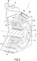
- the figure 2 shows a Hall effect motor 1 in perspective and in partial section.
- a central core 10 extending along a longitudinal axis A, is located a central magnetic winding 12.
- An internal wall 20, of annular shape surrounds the central magnetic winding 12 and the central core 10.
- This internal wall 20 is surrounded by an outer wall 40, of annular shape, so that these two walls delimit an annular channel extending along the axis A, called the discharge channel 50.
- the upstream end of the discharge channel 50 is closed by an injection system 30 which injects gas atoms into this discharge channel 50, and which also constitutes an anode.
- the downstream end 52 of the discharge channel 50 is open.
- peripheral magnetic coils 14 are located on the periphery of the external wall 40.
- the central magnetic coil 12 and the peripheral magnetic coils 14 are used to generate a radial magnetic field B whose intensity is maximum towards the downstream end 52 of the channel of discharge 50.
- a hollow cathode 100 is located outside the outer wall 40, and a potential difference is established between the cathode 100 and the anode (injection system 30). This hollow cathode 100 is positioned so that it ejects electrons in the vicinity of the downstream end 52 of the discharge channel 50.
- the electrons are thus led to describe circumferential trajectories in the discharge channel 50, at its downstream opening 52. These electrons then ionize via shocks the atoms of neutral gas (generally xenon Xe) flowing from upstream to downstream in the discharge channel 50, thereby creating ions. In addition, these electrons create an axial electric field E, which accelerates these ions from the anode (injection system 30 at the bottom of the channel 80) towards the downstream opening 52, so that these ions are ejected at high speed. of the discharge channel 50 through its downstream end 52, which generates the propulsion of the engine.
- neutral gas generally xenon Xe
- Starting the engine requires preheating the cathode 100 by a heating device 60 to a threshold temperature which allows the cathode to emit the quantity of electrons necessary for establishment in the discharge channel 50 of a critical discharge current I cd sufficient to ionize the atoms of the neutral gas in the discharge channel.
- the establishment of this discharge current I cd causes the engine to start.
- the threshold temperature depends on conditions outside the engine, in particular the temperature outside the engine (which can for example vary between -50 ° C and + 70 ° C). To ensure that the engine starts in all conditions, a preheating time is chosen fixed long enough for the highest threshold temperature, corresponding to the most unfavorable external conditions, to be reached.
- the preheating time is too long. This results in unnecessary overheating of the cathode to too high temperatures, and therefore damage thereof, and a reduction in the life of the motor.
- the present invention aims to remedy these drawbacks.
- the invention aims to provide a Hall effect motor in which the preheating time is optimized so that there is no unnecessary overheating of the cathode when starting the motor, and this under any condition of operation of this engine.
- the Hall effect motor as described in claim 1 further comprises a means for measuring the temperature T d of the heating device, and a circuit for regulating this temperature T d so that that the heating device heats up as long as its temperature T d is lower than a threshold temperature T s from which the engine start is likely to occur, and stops heating as soon as the intensity of the discharge current emitted by said cathode reaches a critical intensity of the discharge current I cd which corresponds to the starting of said motor after the threshold temperature T s is reached, said threshold temperature T s being a function of said critical intensity of discharge current I cd .
- the cathode is not heated for a long time beyond a threshold temperature T s , which corresponds to a temperature at which the engine is able to start. In each operating situation of the engine, the cathode is therefore only heated for the time necessary to start the engine. This results in minimization of the damage to the cathode, and a prolongation of the service life of the Hall effect motor.
- the invention also relates to a method for regulating a Hall effect motor comprising a discharge channel whose downstream end is open, a cathode situated outside the discharge channel, an injection system capable of injecting gas atoms in the discharge channel, this injection system being located at the upstream end of the channel and also forming an anode, and a heating device capable of heating the cathode.
- the operation of the motor is optimized so as to heat the cathode 100 only for the time necessary to start the motor, as explained below.
- the Hall effect motor comprises a means 70 for measuring the temperature T d of the heating device 60, and a control circuit 80 for the temperature T d of the heating device 60.
- the figure 1 shows a diagram which illustrates an example of a sequence of steps for starting the Hall effect motor, these steps comprising the steps of starting a Hall effect motor according to the invention.
- the sequence of steps is simplified and does not illustrate the possible safety mechanisms intended, for example, to identify erroneous operating modes when starting the engine, and to stop it if necessary.
- a rectangle indicates an action
- a rhombus indicates a test
- an oval indicates a state.
- an arrow directed downwards indicates that the test has been satisfied
- an arrow directed to the right indicates that the test has not been satisfied.
- step S1 step (a)
- step S2 step (a)
- the temperature of the cathode 100 is measured continuously or at regular intervals so as to detect the moment when this temperature reaches the threshold temperature T s (step S3).
- the temperature of the cathode is not measured directly.
- the temperature T d of the heating device 60 which heats the cathode is measured, and this temperature is compared with the threshold temperature T s , knowing that the temperatures of the heating device 60 and the cathode 100 are substantially equal.
- the heater 60 is integrated inside the cathode 100, as shown in the figure 2 .
- This heating device can also surround the cathode 100.
- the temperature T d of the heating device 60 is determined by means of a measurement means 70.
- the electrical resistivity of the heating device 60 is measured.
- the measuring means 70 is then a means of measuring the electrical resistivity.
- the heating device 60 comprises a heating element which heats the cathode 100
- the electrical resistivity of this heating element is measured.
- thermocouple which measures the temperature of the heating device.
- step (b) When the threshold temperature T s is reached (step (b)), a downstream injection valve located between the enclosure containing the gas and the discharge channel 50 is opened so as to inject the gas into the discharge channel 50 (step S4).
- this downstream injection valve is replaced by a restrictor which allows automatic passage of the gas from this enclosure into the discharge channel with a restricted flow, this flow being a function of the pressure in the enclosure.
- the upstream injection valve is opened at a calculated time so that when the temperature of the heating device 60 reaches the temperature threshold T s , the gas flow through the restrictor is sufficient for the engine to be able to start.
- the threshold temperature T s is the temperature that cathode 100 must normally reach in order for the Hall effect motor to be able to start. Indeed, under favorable engine operating conditions, when this threshold temperature T s is reached, the intensity of the discharge current (electron flow) emitted by said cathode 100 is then equal to or greater than the critical intensity of discharge current I cd at which the atoms of the neutral gas injected into the discharge channel 50 are ionized (step S5), which causes the automatic starting of the engine (auto ignition of the engine - Step S6-1). This first start-up mode is illustrated on the figure 1 .
- the threshold temperature T s is therefore a function of this critical discharge current intensity I cd .
- the threshold temperature T s depends on the material constituting the cathode. Indeed, the starting of the engine occurs when a critical intensity of discharge current I cd , that is to say a flow of electrons, is emitted by the cathode. Now the density of electrons emitted per unit area of the cathode under a given electrical voltage is a function of the material constituting the cathode, and of the geometry of this cathode. Under favorable operating conditions, and for a lanthanum hexaboride cathode (LaB 6 ), the threshold temperature T s is, for certain geometries, around 1700 ° C.
- the threshold temperature T s is of the order of 1300 ° C.
- the intensity of the discharge current emitted by the cathode 100 does not reach the critical intensity of discharge current I cd when the temperature of the cathode 100 passes above the threshold temperature T s .
- it is then necessary to send a voltage pulse to the cathode 100 in order to extract more electrons from the cathode 100, and to reach an intensity of discharge current at least equal to the critical discharge current intensity I cd (step S6-4), in which case the motor starts automatically (step S6-1). If this intensity is not reached after a first voltage pulse, a second, and if necessary more voltage pulses are sent until this intensity is reached.
- step S6-2 the pressure P g of gas in the discharge channel 50 is linked, in a known manner, to the gas pressure in the enclosure which is located immediately upstream and which opens into the discharge channel 50 (see above). It is this gas pressure in the enclosure which is directly measured.
- the voltage pulses are therefore sent to the cathode 100 (step S6-3) only when this additional condition relating to the pressure of the gas in the discharge channel 50 is satisfied. As long as the pressure P g of the gas in the discharge channel 50 remains below the critical pressure P c , the cathode 100 is continued to heat and gas is injected into the discharge channel 50.
- step S6-1 We exit from this state either because the critical discharge current I cd is finally reached in which case there is an auto-ignition of the engine (step S6-1), or because the pressure P g of the gas in the channel discharge 50 becomes greater than the critical pressure P c in which case one begins to send a voltage pulse to the cathode (step S6-2).
- This second start mode is illustrated in figure 1 .
- step S7 step (c)
- the cathode 100 is not unnecessarily heated, and therefore its service life is extended. For example, the engine starts a few tens of seconds after the threshold temperature T s is reached.
- heating of the cathode 100 is stopped for a few seconds to a few tens of seconds (for example between 5 seconds and 300 seconds, and preferably between 5 seconds and 60 seconds) after the threshold temperature T s is reached.
- the diagram of the figure 1 is only one example of the operation of a Hall effect motor according to the invention. Variations in the starting sequence are possible depending on the type of engine, without departing from the scope of the invention.
Landscapes
- Engineering & Computer Science (AREA)
- Chemical & Material Sciences (AREA)
- Combustion & Propulsion (AREA)
- Physics & Mathematics (AREA)
- General Engineering & Computer Science (AREA)
- Mechanical Engineering (AREA)
- Plasma & Fusion (AREA)
- Automation & Control Theory (AREA)
- General Physics & Mathematics (AREA)
- Spectroscopy & Molecular Physics (AREA)
- Plasma Technology (AREA)
- Other Investigation Or Analysis Of Materials By Electrical Means (AREA)
- Combined Controls Of Internal Combustion Engines (AREA)
Description
- La présente invention concerne un moteur à effet Hall comportant un canal de décharge dont l'extrémité aval est ouverte, une cathode située à l'extérieur du canal de décharge, un système d'injection situé à l'extrémité amont du canal de décharge, ce système d'injection étant situé à l'extrémité amont du canal de décharge et formant également anode, et un dispositif de chauffage apte à chauffer la cathode.
- Un moteur à effet Hall est un moteur utilisé par exemple dans le domaine de la propulsion spatiale, car il permet de propulser des objets dans le vide spatial en utilisant une masse de combustible plus faible que dans le cas de moteurs thermiques, et présente une durée de vie importante, de plusieurs milliers d'heures. Le document
US 2009/0058305 décrit un exemple de moteur à effet Hall. - Le moteur à effet Hall étant connu, sa structure et son principe de fonctionnement sont rappelés ci-après brièvement.
- La
figure 2 montre un moteur à effet Hall 1 en perspective et en coupe partielle. Autour d'un noyau central 10 s'étendant selon un axe longitudinal A, est situé un bobinage magnétique central 12. Une paroi interne 20, de forme annulaire, entoure le bobinage magnétique central 12 et le noyau central 10. Cette paroi interne 20 est entourée par une paroi externe 40, de forme annulaire, de telle sorte que ces deux parois délimitent un canal annulaire s'étendant selon l'axe A, appelé canal de décharge 50. - Dans la description qui suit, le terme "interne" désigne une partie plus proche de l'axe A, et le terme "externe" une partie plus éloignée de l'axe A.
- L'extrémité amont du canal de décharge 50 est fermée par un système d'injection 30 qui injecte des atomes de gaz dans ce canal de décharge 50, et qui constitue également une anode. L'extrémité aval 52 du canal de décharge 50 est ouverte.
- Plusieurs bobinages magnétiques périphériques 14 sont situés sur le pourtour de la paroi externe 40. Le bobinage magnétique central 12 et les bobinages magnétiques périphériques 14 servent à générer un champ magnétique radial B dont l'intensité est maximale vers l'extrémité aval 52 du canal de décharge 50.
- Une cathode creuse 100 se situe à l'extérieur de la paroi externe 40, et il est établit une différence de potentiel entre la cathode 100 et l'anode (système d'injection 30). Cette cathode creuse 100 est positionnée de telle sorte qu'elle éjecte des électrons au voisinage de l'extrémité aval 52 du canal de décharge 50.
- Ces électrons se dirigent, dans le canal de décharge 50, vers le système d'injection 30 sous l'influence du champ électrique généré par la différence de potentiel entre la cathode 100 et l'anode, mais ils se retrouvent en partie piégés par le champ magnétique B au voisinage de l'ouverture aval 52 du canal de décharge 50.
- Les électrons sont ainsi amenés à décrire des trajectoires circonférentielles dans le canal de décharge 50, au niveau de son ouverture aval 52. Ces électrons ionisent alors via des chocs les atomes de gaz neutre (en général du xénon Xe) circulant de l'amont vers l'aval dans le canal de décharge 50, créant ainsi des ions. De plus, ces électrons créent un champ électrique E axial, qui accélère ces ions depuis l'anode (système d'injection 30 au fond du canal 80) vers l'ouverture aval 52, de telle sorte que ces ions sont éjectés à grande vitesse du canal de décharge 50 par son extrémité aval 52, ce qui engendre la propulsion du moteur.
- Le démarrage du moteur nécessite le préchauffage de la cathode 100 par un dispositif de chauffage 60 jusqu'à une température seuil qui permet l'émission par la cathode de la quantité d'électrons nécessaire à l'établissement dans le canal de décharge 50 d'un courant de décharge critique Icd suffisant pour ioniser les atomes du gaz neutre dans le canal de décharge. L'établissement de ce courant de décharge Icd entraîne le démarrage du moteur.
- En général, l'atteinte de cette température seuil est suffisante pour l'établissement de ce courant de décharge Icd.
- Dans certaines conditions de fonctionnement défavorables, il faut, pour établir ce courant de décharge Icd, envoyer un ou plusieurs pulses de tension sur la cathode une fois la température seuil atteinte.
- En pratique, la température seuil dépend des conditions extérieures au moteur, notamment la température extérieure au moteur (qui peut par exemple varier entre -50°C et +70°C). Afin d'assurer un démarrage du moteur dans toutes les conditions, on choisit une durée de préchauffage fixe suffisamment longue pour que la température seuil la plus élevée, correspondant aux conditions extérieures les plus défavorables, soit atteinte.
- Ainsi, dans la majorité des cas, qui correspondent à des conditions favorables ou peu défavorables, la durée de préchauffage est trop longue. Il en résulte une surchauffe inutile de la cathode jusqu'à des températures trop élevées, et donc un endommagement de celle-ci, et une réduction de la durée de vie du moteur.
- La présente invention vise à remédier à ces inconvénients.
- L'invention vise à proposer un moteur à effet Hall dans lequel la durée de préchauffage est optimisée de telle sorte qu'il ne se produise pas de surchauffe inutile de la cathode lors du démarrage du moteur, et ce dans n'importe quelle condition de fonctionnement de ce moteur.
- Ce but est atteint grâce au fait que le moteur à effet Hall tel que décrit dans la revendication 1 comprend en outre un moyen de mesure de la température Td du dispositif de chauffage, et un circuit de régulation de cette température Td de telle sorte que le dispositif de chauffage chauffe tant que sa température Td est inférieure à une température seuil Ts à partir de laquelle le démarrage du moteur est susceptible de se produire, et cesse de chauffer dès que l'intensité du courant de décharge émis par ladite cathode atteint une intensité critique du courant de décharge Icd qui correspond au démarrage dudit moteur après que la température seuil Ts est atteinte, ladite température seuil Ts étant fonction de ladite intensité critique de courant de décharge Icd.
- Grâce à ces dispositions, la cathode n'est pas chauffée longtemps au-delà d'une température seuil Ts, qui correspond à une température à laquelle le moteur est apte à démarrer. Dans chaque situation de fonctionnement du moteur, la cathode n'est donc chauffée que le temps nécessaire au démarrage du moteur. Il en résulte une minimisation de l'endommagement de la cathode, et une prolongation de la durée de vie du moteur à effet Hall.
- L'invention concerne également un procédé de régulation d'un moteur à effet Hall comportant un canal de décharge dont l'extrémité aval est ouverte, une cathode située à l'extérieur du canal de décharge, un système d'injection apte à injecter des atomes de gaz dans le canal de décharge, ce système d'injection étant situé à l'extrémité amont du canal de décharge et formant également anode, et un dispositif de chauffage apte à chauffer la cathode.
- Selon l'invention, ce procédé selon la revendication 3 comprend les étapes suivantes :
- (a) On chauffe la cathode à l'aide du dispositif de chauffage et on mesure simultanément la température Td du dispositif de chauffage,
- (b) On continue ce chauffage de la cathode tant que température Td est inférieure à une température seuil Ts à partir de laquelle le démarrage du moteur est susceptible de se produire,
- (c) On cesse ce chauffage dès que l'intensité du courant de décharge émis par ladite cathode atteint ladite intensité critique du courant de décharge Icd après que la température seuil Ts est atteinte.
- L'invention sera bien comprise et ses avantages apparaîtront mieux, à la lecture de la description détaillée qui suit, d'un mode de réalisation représenté à titre d'exemple non limitatif. La description se réfère aux dessins annexés sur lesquels :
- la
figure 1 est un diagramme illustrant la séquence des étapes du procédé selon l'invention, - la
figure 2 est une vue en coupe en en perspective d'un moteur à effet Hall selon l'invention, illustrant sa structure générale. - Le fonctionnement général d'un moteur à effet Hall a été décrit ci-dessus, en référence à la
figure 2 . - De plus, dans le moteur à effet Hall selon l'invention, le fonctionnement du moteur est optimisé de façon à ne chauffer la cathode 100 que le temps nécessaire au démarrage du moteur, comme expliqué ci-dessous.
- Ainsi, le moteur à effet Hall comprend un moyen de mesure 70 de la température Td du dispositif de chauffage 60, et un circuit de régulation 80 de la température Td du dispositif de chauffage 60.
- On explique ci-dessous comment fonctionne ce circuit de régulation 80.
- La
figure 1 montre un diagramme qui illustre un exemple d'une séquence des étapes du démarrage du moteur à effet Hall, ces étapes comprenant les étapes du démarrage d'un moteur à effet Hall selon l'invention. La séquence des étapes est simplifiée et ne n'illustre pas les possibles mécanismes de sécurité destinés par exemple à identifier les modes fonctionnement erronés lors de démarrage du moteur, et à le stopper si nécessaire. Un rectangleindique une action, un losange indique un test, un ovale
 indique un état. En sortie d'un test, une flèche dirigée vers le bas indique que le test a été satisfait, une flèche dirigée vers la droite indique que le test n'a pas été satisfait.
- Les étapes du démarrage sont référencées comme suit :
- Etape S1: Allumage du chauffage de la cathode.
- Etape S2: Ouverture de la vanne d'injection amont du gaz.
- Etape S3: La température seuil Ts est-elle atteinte ?
- Etape S4: Ouverture de la vanne d'injection aval du gaz dans le canal de décharge.
- Etape S5: Le courant critique de décharge Icd est-il atteint ?
- Etape S6-1 :Auto-allumage du moteur.
- Etape S7: Arrêt du chauffage de la cathode.
- Etape S6-2 :La pression du gaz dans le canal de décharge est-elle supérieure à la pression critique Pc ?
- Etape S6-3 :Envoi d'un puise de tension sur la cathode.
- Etape S6-4 :Le courant critique de décharge Icd est-il atteint ?
- Etape S7: Arrêt ou réduction du chauffage de la cathode.
- Initialement, on allume le dispositif de chauffage 60 de façon à commencer le chauffage de la cathode 100 (étape S1 = étape (a)). On ouvre alors une vanne d'injection amont du gaz (étape S2) de façon à amener le gaz dans une enceinte (non-représentée), prêt à être injecté dans le canal de décharge 50.
- Durant la phase de chauffage du dispositif de chauffage 60, la température de la cathode 100 est mesurée en continu ou à intervalles réguliers de façon à détecter le moment où cette température atteint la température seuil Ts (étape S3).
- En pratique, on ne mesure pas directement la température de la cathode. On mesure la température Td du dispositif de chauffage 60 qui chauffe la cathode, et on compare cette température avec la température seuil Ts, sachant que les températures du dispositif de chauffage 60 et de la cathode 100 sont sensiblement égales. Par exemple, le dispositif de chauffage 60 est intégré à l'intérieur de la cathode 100, comme représenté sur la
figure 2 . - Ce dispositif de chauffage peut également entourer la cathode 100.
- La température Td du dispositif de chauffage 60 est déterminée grâce à un moyen de mesure 70.
- Par exemple, on mesure la résistivité électrique du dispositif de chauffage 60. Le moyen de mesure 70 est alors un moyen de mesure de la résistivité électrique. Dans le cas où le dispositif de chauffage 60 comprend un élément chauffant qui chauffe la cathode 100, on mesure la résistivité électrique de cet élément chauffant.
- D'autres moyens de mesure sont possibles, par exemple un thermocouple, qui mesure la température du dispositif de chauffage.
- Lorsque la température seuil Ts est atteinte (étape (b)), une vanne d'injection aval située entre l'enceinte contenant le gaz et le canal de décharge 50 est ouverte de façon à injecter le gaz dans le canal de décharge 50 (étape S4).
- Dans certains cas, cette vanne d'injection aval est remplacée par un restricteur qui permet un passage automatique du gaz depuis cette enceinte dans le canal de décharge avec un débit restreint, ce débit étant fonction de la pression dans l'enceinte. Dans ce cas, étant donné que la gamme de montée en température Td du dispositif de chauffage 60 est connue, on ouvre la vanne d'injection amont à un temps calculé de telle sorte que lorsque la température du dispositif de chauffage 60 atteint la température seuil Ts, le débit de gaz au travers du restricteur soit suffisant pour que le moteur soit susceptible de démarrer.
- La température seuil Ts est la température que doit normalement atteindre la cathode 100 pour que le moteur à effet Hall soit susceptible de démarrer. En effet, dans des conditions favorables de fonctionnement du moteur, lorsque cette température seuil Ts est atteinte, l'intensité du courant de décharge (flux d'électrons) émis par ladite cathode 100 est alors égale ou supérieure à l'intensité critique de courant de décharge Icd à laquelle les atomes du gaz neutre injectés dans le canal de décharge 50 sont ionisés (étape S5), ce qui entraine le démarrage automatique du moteur (auto allumage du moteur - Étape S6-1). Ce premier mode de démarrage est illustré sur la
figure 1 . - La température seuil Ts est donc une fonction de cette intensité critique de courant de décharge Icd.
- La température seuil Ts dépend du matériau constituant la cathode. En effet, le démarrage du moteur se produit lorsqu'une intensité critique de courant de décharge Icd, c'est-à-dire un flux d'électrons, est émise par la cathode. Or la densité d'électrons émise par unité de surface de la cathode sous une tension électrique donnée est fonction du matériau constituant la cathode, et de la géométrie de cette cathode. Dans des conditions favorables de fonctionnement, et pour une cathode en héxaborure de lanthane (LaB6) la température seuil Ts est, pour certaines géométries, environ de 1700 °C.
- Dans le cas d'une cathode constituée d'oxydes de baryum imprégnant une matrice en tungstène, la température seuil Ts est de l'ordre de 1300°C.
- Dans certaines conditions défavorables, l'intensité du courant de décharge émis par la cathode 100 n'atteint pas l'intensité critique de courant de décharge Icd lorsque la température de la cathode 100 passe au dessus de la température seuil Ts. Afin d'amorcer le démarrage du moteur, il est alors nécessaire d'envoyer sur la cathode 100 un pulse de tension (étape S6-3) afin d'extraire plus d'électrons de la cathode 100, et d'atteindre une intensité de courant de décharge au moins égale à l'intensité critique de courant de décharge Icd (étape S6-4), auquel cas le moteur démarre automatiquement (étape S6-1). Si cette intensité n'est pas atteinte après un premier pulse de tension, un deuxième, et si nécessaire davantage de pulses de tension sont envoyés jusqu'à ce que cette intensité soit atteinte.
- Cependant, un tel envoi de pulses n'est efficace que si la pression Pg du gaz dans le canal de décharge 50 est supérieure à une pression critique Pc (étape S6-2). Dans le cadre du moteur à effet Hall, la pression Pg de gaz dans le canal de décharge est liée, de façon connue, à la pression de gaz dans l'enceinte qui est située immédiatement en amont et qui débouche dans le canal de décharge 50 (voir ci-dessus). C'est cette pression de gaz dans l'enceinte qui est directement mesurée.
- Les pulses de tension ne sont donc envoyés sur la cathode 100 (étape S6-3) que lorsque cette condition supplémentaire portant sur la pression du gaz dans le canal de décharge 50 est satisfaite. Tant que la pression Pg du gaz dans le canal de décharge 50 reste inférieure à la pression critique Pc, on continue à chauffer la cathode 100 et à injecter du gaz dans le canal de décharge 50.
- On sort de cet état soit parce que le courant critique de décharge Icd est finalement atteint auquel cas il se produit un autoallumage du moteur (étape S6-1), soit parce que la pression Pg du gaz dans le canal de décharge 50 devient supérieure à la pression critique Pc auquel cas on commence à envoyer un pulse de tension sur la cathode (étape S6-2). Ce second mode de démarrage est illustré en
figure 1 . - Dans tous les cas (premier mode et second mode), dès que le moteur a démarré, ce qui se produit peu de temps après la température seuil Ts atteinte par la cathode 100, le chauffage de la cathode 100 est interrompu ou réduite (étape S7 = étape (c)). Ainsi, on ne chauffe pas inutilement la cathode 100, et on prolonge donc sa durée de vie. Par exemple, le moteur démarre quelques dizaines de secondes après la température seuil Ts atteinte.
- Ainsi, on cesse de chauffer la cathode 100 quelques secondes à quelques dizaines de secondes (par exemple entre 5 secondes et 300 secondes, et de préférence entre 5 secondes et 60 secondes) après que la température seuil Ts est atteinte.
- Dans un cas particulier du second cas, on peut être amené à poursuivre le chauffage de la cathode 100 jusqu'à plusieurs minutes après le démarrage du moteur 1. En effet, on se trouve alors dans le cas où le moteur a démarré sans que le courant de décharge ait atteint son intensité critique Icd, et où la pression de gaz en amont est faible car on est en train d'utiliser les dernières réserves de gaz. On poursuit alors le chauffage de la cathode 100 jusqu'à plusieurs minutes après le démarrage du moteur 1 en augmentant la pression de gaz afin d'utiliser de façon efficace ces dernières réserves de gaz.
- Le diagramme de la
figure 1 n'est qu'un exemple du fonctionnement d'un moteur à effet Hall selon l'invention. Des variations de la séquence de démarrage sont possibles en fonction du type de moteur, sans sortir du cadre de l'invention.
Claims (5)
- Moteur à effet Hall (1) comportant un canal de décharge (50) dont l'extrémité aval (52) est ouverte, une cathode (100) située à l'extérieur dudit canal de décharge (50), un système d'injection (30) apte à injecter des atomes de gaz dans ledit canal de décharge (50), ce système d'injection (30) étant situé à l'extrémité amont dudit canal de décharge (50) et formant également anode, et un dispositif de chauffage (60) apte à chauffer ladite cathode (100), ledit moteur (1) étant caractérisé en ce qu'il comprend en outre un moyen de mesure (70) de la température Td dudit dispositif de chauffage (60), et un circuit de régulation (80) de ladite température Td de telle sorte que ledit dispositif de chauffage (60) chauffe tant que sa température Td est inférieure à une température seuil Ts à partir de laquelle le démarrage dudit moteur est susceptible de se produire, et cesse de chauffer dès que l'intensité du courant de décharge émis par ladite cathode (100) atteint une intensité critique du courant de décharge Icd qui correspond au démarrage dudit moteur, après que ladite température seuil Ts est atteinte, ladite température seuil Ts étant fonction de ladite intensité critique de courant de décharge Icd.
- Moteur à effet Hall (1) selon la revendication 1 caractérisé en ce que la température Td dudit dispositif de chauffage (60) est déterminée grâce à la mesure de la résistivité électrique de ce dispositif de chauffage (60).
- Procédé de régulation d'un moteur à effet Hall (1) selon la revendication 1 ou 2, caractérisé en ce qu'il comprend les étapes suivantes :(a) On chauffe ladite cathode (100) à l'aide du dispositif de chauffage (60) et on mesure simultanément la température Td dudit dispositif de chauffage (60),(b) On continue ce chauffage de ladite cathode (100) tant que la température Td est inférieure à ladite température seuil Ts à partir de laquelle le démarrage dudit moteur est susceptible de se produire,(c) On cesse ce chauffage dès que l'intensité du courant de décharge émis par ladite cathode (100) atteint ladite intensité critique du courant de décharge Icd après que ladite température seuil Ts est atteinte.
- Procédé de régulation selon la revendications 3, caractérisé en ce que: après que ladite température de seuil Ts est atteinte par ledit dispositif de chauffage (60), lorsque l'intensité du courant de décharge émis par ladite cathode (100) est inférieure à ladite intensité critique de courant de décharge Icd et la pression Pg dudit gaz dans ledit canal de décharge (50) est inférieure à une pression critique Pc, on continue à chauffer ladite cathode (100) et à injecter du gaz dans ledit canal de décharge (50).
- Procédé de régulation selon la revendication 3, caractérisé en ce que, après que ladite température de seuil Ts est atteinte par ledit dispositif de chauffage (60), lorsque l'intensité du courant de décharge émis par ladite cathode (100) est inférieure à ladite intensité critique de courant de décharge Icd et la pression Pg dudit gaz dans ledit canal de décharge (50) est supérieure à une pression critique Pc, au moins un pulse de tension est envoyé sur ladite cathode (100) jusqu'à ce que l'intensité du courant de décharge devienne égale à ladite intensité critique de courant de décharge Icd de façon à permettre le démarrage dudit moteur.
Applications Claiming Priority (2)
| Application Number | Priority Date | Filing Date | Title |
|---|---|---|---|
| FR1053311A FR2959534B1 (fr) | 2010-04-29 | 2010-04-29 | Moteur a effet hall avec regulation de la temperature du dispositif de chauffage de la cathode |
| PCT/FR2011/050980 WO2011135271A1 (fr) | 2010-04-29 | 2011-04-29 | Moteur a effet hall avec regulation de la temperature du dispositif de chauffage de la cathode |
Publications (2)
| Publication Number | Publication Date |
|---|---|
| EP2564064A1 EP2564064A1 (fr) | 2013-03-06 |
| EP2564064B1 true EP2564064B1 (fr) | 2019-12-18 |
Family
ID=43432361
Family Applications (1)
| Application Number | Title | Priority Date | Filing Date |
|---|---|---|---|
| EP11723536.6A Active EP2564064B1 (fr) | 2010-04-29 | 2011-04-29 | Moteur a effet hall avec regulation de la temperature du dispositif de chauffage de la cathode |
Country Status (8)
| Country | Link |
|---|---|
| US (1) | US9309871B2 (fr) |
| EP (1) | EP2564064B1 (fr) |
| JP (1) | JP6069655B2 (fr) |
| CN (1) | CN102869883B (fr) |
| FR (1) | FR2959534B1 (fr) |
| IL (1) | IL222535A (fr) |
| RU (1) | RU2564733C2 (fr) |
| WO (1) | WO2011135271A1 (fr) |
Families Citing this family (16)
| Publication number | Priority date | Publication date | Assignee | Title |
|---|---|---|---|---|
| FR3032325A1 (fr) * | 2015-01-30 | 2016-08-05 | Snecma | Propulseur a effet hall et engin spatial comprenant un tel propulseur |
| CN105003409A (zh) * | 2015-07-16 | 2015-10-28 | 兰州空间技术物理研究所 | 一种霍尔推力器的阴极中心布局 |
| CN105822515B (zh) * | 2016-04-14 | 2019-03-29 | 哈尔滨工业大学 | 空间碎片等离子体推进器 |
| FR3053784B1 (fr) * | 2016-07-07 | 2020-01-17 | Airbus Defence And Space Sas | Procedes de determination et de regulation de la temperature d’un propulseur electrique |
| FR3053742B1 (fr) * | 2016-07-07 | 2020-03-13 | Airbus Defence And Space Sas | Procede de controle d’un propulseur electrique a effet hall |
| CN106050592B (zh) * | 2016-07-27 | 2018-09-07 | 哈尔滨工业大学 | 霍尔推力器散热支架 |
| CN108533469B (zh) * | 2018-03-09 | 2020-01-14 | 中国科学院微电子研究所 | 自加热式电推进器工质供给装置以及电推进器 |
| CN111219306B (zh) * | 2019-03-21 | 2020-12-11 | 哈尔滨工业大学 | 一种双磁屏的霍尔推力器 |
| EP3836762B1 (fr) * | 2019-12-13 | 2023-02-08 | Airbus Defence and Space GmbH | Neutraliseur pour un moteur-fusée ionique, procédé de fonctionnement d'un neutraliseur et moteur-fusée ionique |
| CN113266542B (zh) * | 2021-06-29 | 2022-05-17 | 哈尔滨工业大学 | 一种霍尔推力器磁路散热结构 |
| EP4299449A1 (fr) * | 2022-06-27 | 2024-01-03 | Airbus Defence and Space SAS | Procédé de pilotage d'un propulseur plasmique |
| CN115450876B (zh) * | 2022-10-17 | 2023-07-18 | 兰州空间技术物理研究所 | 一种连续可调离子电推进推力控制及阈值保护方法 |
| CN115681053B (zh) * | 2023-01-03 | 2023-06-02 | 国科大杭州高等研究院 | 一种自维持霍尔推力系统的运行方法 |
| CN115681057B (zh) * | 2023-01-03 | 2023-06-02 | 国科大杭州高等研究院 | 一种霍尔推进系统及其运行方法 |
| WO2024146568A2 (fr) * | 2023-01-03 | 2024-07-11 | 国科大杭州高等研究院 | Procédé de fonctionnement pour système de poussée à effet hall autonome, cathode de milieu non actif, propulseur à effet hall la comprenant, et équipement spatial |
| CN115839324B (zh) * | 2023-01-03 | 2023-06-02 | 国科大杭州高等研究院 | 霍尔推进系统的运行方法 |
Family Cites Families (13)
| Publication number | Priority date | Publication date | Assignee | Title |
|---|---|---|---|---|
| US4086466A (en) * | 1976-04-30 | 1978-04-25 | Scharlack Ronald S | Automatic heater controller |
| GB1573679A (en) * | 1978-05-31 | 1980-08-28 | English Electric Valve Co Ltd | Arrangements including electrical heating elements |
| US4733530A (en) | 1986-08-04 | 1988-03-29 | Hughes Aircraft Company | Emission current control system for multiple hollow cathode devices |
| FR2693770B1 (fr) * | 1992-07-15 | 1994-10-14 | Europ Propulsion | Moteur à plasma à dérive fermée d'électrons. |
| RU2030016C1 (ru) * | 1992-11-11 | 1995-02-27 | Опытное конструкторское бюро "Факел" | Плазменный катод-компенсатор |
| US5646476A (en) * | 1994-12-30 | 1997-07-08 | Electric Propulsion Laboratory, Inc. | Channel ion source |
| US6518693B1 (en) * | 1998-11-13 | 2003-02-11 | Aerojet-General Corporation | Method and apparatus for magnetic voltage isolation |
| RU2219683C2 (ru) * | 2001-11-28 | 2003-12-20 | Федеральное государственное унитарное предприятие Российского авиационно-космического агентства "Опытное конструкторское бюро "Факел" | Источник плазмы и способы его работы (варианты) |
| US6724160B2 (en) * | 2002-04-12 | 2004-04-20 | Kaufman & Robinson, Inc. | Ion-source neutralization with a hot-filament cathode-neutralizer |
| JP2007071055A (ja) * | 2005-09-05 | 2007-03-22 | Osaka Univ | 磁場集中構造を有する磁気回路を備えたホールスラスタ |
| JP4650258B2 (ja) * | 2005-12-27 | 2011-03-16 | 三菱電機株式会社 | 電源装置 |
| JP4697460B2 (ja) * | 2006-10-04 | 2011-06-08 | 三菱電機株式会社 | 電源装置 |
| US8143788B2 (en) * | 2007-08-31 | 2012-03-27 | California Institute Of Technology | Compact high current rare-earth emitter hollow cathode for hall effect thrusters |
-
2010
- 2010-04-29 FR FR1053311A patent/FR2959534B1/fr active Active
-
2011
- 2011-04-29 EP EP11723536.6A patent/EP2564064B1/fr active Active
- 2011-04-29 US US13/643,109 patent/US9309871B2/en active Active
- 2011-04-29 WO PCT/FR2011/050980 patent/WO2011135271A1/fr not_active Ceased
- 2011-04-29 RU RU2012148835/06A patent/RU2564733C2/ru active
- 2011-04-29 CN CN201180021448.6A patent/CN102869883B/zh active Active
- 2011-04-29 JP JP2013506720A patent/JP6069655B2/ja active Active
-
2012
- 2012-10-18 IL IL222535A patent/IL222535A/en active IP Right Grant
Non-Patent Citations (1)
| Title |
|---|
| None * |
Also Published As
| Publication number | Publication date |
|---|---|
| CN102869883B (zh) | 2016-07-06 |
| US9309871B2 (en) | 2016-04-12 |
| IL222535A (en) | 2016-09-29 |
| RU2564733C2 (ru) | 2015-10-10 |
| RU2012148835A (ru) | 2014-06-10 |
| WO2011135271A1 (fr) | 2011-11-03 |
| IL222535A0 (en) | 2012-12-31 |
| CN102869883A (zh) | 2013-01-09 |
| US20130125526A1 (en) | 2013-05-23 |
| EP2564064A1 (fr) | 2013-03-06 |
| JP2013531755A (ja) | 2013-08-08 |
| FR2959534A1 (fr) | 2011-11-04 |
| JP6069655B2 (ja) | 2017-02-01 |
| FR2959534B1 (fr) | 2012-07-13 |
Similar Documents
| Publication | Publication Date | Title |
|---|---|---|
| WO2011135271A1 (fr) | Moteur a effet hall avec regulation de la temperature du dispositif de chauffage de la cathode | |
| FR2536507A1 (fr) | Procede pour faire fonctionner un bruleur a gazeification pour carburant liquide, bruleur a gazeification et dispositif de commande pour la mise en oeuvre dudit procede | |
| EP3030844B1 (fr) | Procédé de gestion du chauffage d'eau dans une cuve d'un chauffe-eau | |
| FR2944065A1 (fr) | Demarreur monte sur un vehicule equipe d'un appareil d'arret au ralenti | |
| WO2013124566A1 (fr) | Injecteur de carburant pour une turbomachine | |
| FR3082236A1 (fr) | Procede de detection d’un catalyseur d’oxydation dans la ligne d’echappement d’un moteur diesel et utilisation dudit procede pour des vehicules automobiles equipes de moteurs diesel | |
| WO2011007083A1 (fr) | Methode de fabrication de conduites tubulaires rigides a double enveloppe et installation dediee a la fabrication de ces conduites | |
| FR2910561A1 (fr) | Systeme d'alimentation en carburant d'un moteur a combustion interne | |
| EP1041277B1 (fr) | Dispositif de commande de démarreur de véhicule automobile protégeant ce dernier de l'usure | |
| FR3044612B1 (fr) | Controle de la depressurisation d'un reservoire de carburant d'un vehicule automobile | |
| FR3033593A1 (fr) | Systeme chauffant de lubrification de moteur | |
| WO2016207556A1 (fr) | Procédé et calculateur pour le contrôle de la pression à l'intérieur d'un réservoir de carburant d'un véhicule automobile | |
| FR3084914A1 (fr) | Circuit de refroidissement d'un groupe motopropulseur thermique ou hybride et procede de commande d'un tel circuit | |
| CA3068399C (fr) | Procede de regulation de la temperature d'un propulseur electrique | |
| FR3080154A1 (fr) | Procede de fabrication d'un propulseur electrique | |
| FR2773593A1 (fr) | Systeme d'injection de carburant pour moteurs a combustion interne | |
| FR3042229B1 (fr) | Commande d'une vanne d'isolation d'un reservoir de carburant d'un vehicule automobile. | |
| FR2928969A1 (fr) | Procede de detection de defaillance d'une electrovanne d'injection a l'echappement de moteur a combustion | |
| FR2484023A1 (fr) | Dispositif d'echauffement prealable de carburant, pour moteurs diesel | |
| EP1041278A1 (fr) | Dispositif de commande de démarreur de véhicule automobile produisant une usure faible du démarreur | |
| FR3007910A1 (fr) | Dispositif de rehaussement de tension de demarreur et combinaison correspondante d'un demarreur et dudit dispositif de rehaussement de tension | |
| FR3013770A1 (fr) | Procede de demarrage d'un moteur thermique et moteur thermique pour la mise en oeuvre du procede | |
| WO2018037193A1 (fr) | Procede de gestion d'une panne de vanne de demarrage d'une turbomachine | |
| FR3075273A1 (fr) | Procede de gestion d'une pompe a piston pour moteur thermique | |
| FR3075276A1 (fr) | Circuit d'allumage d'une bougie d'un moteur de vehicule |
Legal Events
| Date | Code | Title | Description |
|---|---|---|---|
| PUAI | Public reference made under article 153(3) epc to a published international application that has entered the european phase |
Free format text: ORIGINAL CODE: 0009012 |
|
| 17P | Request for examination filed |
Effective date: 20121123 |
|
| AK | Designated contracting states |
Kind code of ref document: A1 Designated state(s): AL AT BE BG CH CY CZ DE DK EE ES FI FR GB GR HR HU IE IS IT LI LT LU LV MC MK MT NL NO PL PT RO RS SE SI SK SM TR |
|
| DAX | Request for extension of the european patent (deleted) | ||
| STAA | Information on the status of an ep patent application or granted ep patent |
Free format text: STATUS: EXAMINATION IS IN PROGRESS |
|
| 17Q | First examination report despatched |
Effective date: 20170814 |
|
| RAP1 | Party data changed (applicant data changed or rights of an application transferred) |
Owner name: SAFRAN AIRCRAFT ENGINES |
|
| GRAP | Despatch of communication of intention to grant a patent |
Free format text: ORIGINAL CODE: EPIDOSNIGR1 |
|
| STAA | Information on the status of an ep patent application or granted ep patent |
Free format text: STATUS: GRANT OF PATENT IS INTENDED |
|
| RIC1 | Information provided on ipc code assigned before grant |
Ipc: H01J 1/15 20060101ALI20190624BHEP Ipc: F03H 1/00 20060101AFI20190624BHEP Ipc: H01J 1/22 20060101ALI20190624BHEP Ipc: G05D 23/24 20060101ALI20190624BHEP |
|
| INTG | Intention to grant announced |
Effective date: 20190708 |
|
| GRAS | Grant fee paid |
Free format text: ORIGINAL CODE: EPIDOSNIGR3 |
|
| GRAA | (expected) grant |
Free format text: ORIGINAL CODE: 0009210 |
|
| STAA | Information on the status of an ep patent application or granted ep patent |
Free format text: STATUS: THE PATENT HAS BEEN GRANTED |
|
| AK | Designated contracting states |
Kind code of ref document: B1 Designated state(s): AL AT BE BG CH CY CZ DE DK EE ES FI FR GB GR HR HU IE IS IT LI LT LU LV MC MK MT NL NO PL PT RO RS SE SI SK SM TR |
|
| REG | Reference to a national code |
Ref country code: GB Ref legal event code: FG4D Free format text: NOT ENGLISH |
|
| REG | Reference to a national code |
Ref country code: CH Ref legal event code: EP |
|
| REG | Reference to a national code |
Ref country code: IE Ref legal event code: FG4D Free format text: LANGUAGE OF EP DOCUMENT: FRENCH |
|
| REG | Reference to a national code |
Ref country code: DE Ref legal event code: R096 Ref document number: 602011064075 Country of ref document: DE |
|
| REG | Reference to a national code |
Ref country code: AT Ref legal event code: REF Ref document number: 1214887 Country of ref document: AT Kind code of ref document: T Effective date: 20200115 |
|
| REG | Reference to a national code |
Ref country code: NL Ref legal event code: MP Effective date: 20191218 |
|
| PG25 | Lapsed in a contracting state [announced via postgrant information from national office to epo] |
Ref country code: LV Free format text: LAPSE BECAUSE OF FAILURE TO SUBMIT A TRANSLATION OF THE DESCRIPTION OR TO PAY THE FEE WITHIN THE PRESCRIBED TIME-LIMIT Effective date: 20191218 Ref country code: SE Free format text: LAPSE BECAUSE OF FAILURE TO SUBMIT A TRANSLATION OF THE DESCRIPTION OR TO PAY THE FEE WITHIN THE PRESCRIBED TIME-LIMIT Effective date: 20191218 Ref country code: FI Free format text: LAPSE BECAUSE OF FAILURE TO SUBMIT A TRANSLATION OF THE DESCRIPTION OR TO PAY THE FEE WITHIN THE PRESCRIBED TIME-LIMIT Effective date: 20191218 Ref country code: BG Free format text: LAPSE BECAUSE OF FAILURE TO SUBMIT A TRANSLATION OF THE DESCRIPTION OR TO PAY THE FEE WITHIN THE PRESCRIBED TIME-LIMIT Effective date: 20200318 Ref country code: GR Free format text: LAPSE BECAUSE OF FAILURE TO SUBMIT A TRANSLATION OF THE DESCRIPTION OR TO PAY THE FEE WITHIN THE PRESCRIBED TIME-LIMIT Effective date: 20200319 Ref country code: NO Free format text: LAPSE BECAUSE OF FAILURE TO SUBMIT A TRANSLATION OF THE DESCRIPTION OR TO PAY THE FEE WITHIN THE PRESCRIBED TIME-LIMIT Effective date: 20200318 Ref country code: LT Free format text: LAPSE BECAUSE OF FAILURE TO SUBMIT A TRANSLATION OF THE DESCRIPTION OR TO PAY THE FEE WITHIN THE PRESCRIBED TIME-LIMIT Effective date: 20191218 |
|
| REG | Reference to a national code |
Ref country code: LT Ref legal event code: MG4D |
|
| PG25 | Lapsed in a contracting state [announced via postgrant information from national office to epo] |
Ref country code: RS Free format text: LAPSE BECAUSE OF FAILURE TO SUBMIT A TRANSLATION OF THE DESCRIPTION OR TO PAY THE FEE WITHIN THE PRESCRIBED TIME-LIMIT Effective date: 20191218 Ref country code: HR Free format text: LAPSE BECAUSE OF FAILURE TO SUBMIT A TRANSLATION OF THE DESCRIPTION OR TO PAY THE FEE WITHIN THE PRESCRIBED TIME-LIMIT Effective date: 20191218 |
|
| PG25 | Lapsed in a contracting state [announced via postgrant information from national office to epo] |
Ref country code: AL Free format text: LAPSE BECAUSE OF FAILURE TO SUBMIT A TRANSLATION OF THE DESCRIPTION OR TO PAY THE FEE WITHIN THE PRESCRIBED TIME-LIMIT Effective date: 20191218 |
|
| PG25 | Lapsed in a contracting state [announced via postgrant information from national office to epo] |
Ref country code: CZ Free format text: LAPSE BECAUSE OF FAILURE TO SUBMIT A TRANSLATION OF THE DESCRIPTION OR TO PAY THE FEE WITHIN THE PRESCRIBED TIME-LIMIT Effective date: 20191218 Ref country code: RO Free format text: LAPSE BECAUSE OF FAILURE TO SUBMIT A TRANSLATION OF THE DESCRIPTION OR TO PAY THE FEE WITHIN THE PRESCRIBED TIME-LIMIT Effective date: 20191218 Ref country code: NL Free format text: LAPSE BECAUSE OF FAILURE TO SUBMIT A TRANSLATION OF THE DESCRIPTION OR TO PAY THE FEE WITHIN THE PRESCRIBED TIME-LIMIT Effective date: 20191218 Ref country code: PT Free format text: LAPSE BECAUSE OF FAILURE TO SUBMIT A TRANSLATION OF THE DESCRIPTION OR TO PAY THE FEE WITHIN THE PRESCRIBED TIME-LIMIT Effective date: 20200513 Ref country code: EE Free format text: LAPSE BECAUSE OF FAILURE TO SUBMIT A TRANSLATION OF THE DESCRIPTION OR TO PAY THE FEE WITHIN THE PRESCRIBED TIME-LIMIT Effective date: 20191218 |
|
| PG25 | Lapsed in a contracting state [announced via postgrant information from national office to epo] |
Ref country code: SK Free format text: LAPSE BECAUSE OF FAILURE TO SUBMIT A TRANSLATION OF THE DESCRIPTION OR TO PAY THE FEE WITHIN THE PRESCRIBED TIME-LIMIT Effective date: 20191218 Ref country code: IS Free format text: LAPSE BECAUSE OF FAILURE TO SUBMIT A TRANSLATION OF THE DESCRIPTION OR TO PAY THE FEE WITHIN THE PRESCRIBED TIME-LIMIT Effective date: 20200418 Ref country code: SM Free format text: LAPSE BECAUSE OF FAILURE TO SUBMIT A TRANSLATION OF THE DESCRIPTION OR TO PAY THE FEE WITHIN THE PRESCRIBED TIME-LIMIT Effective date: 20191218 |
|
| REG | Reference to a national code |
Ref country code: DE Ref legal event code: R097 Ref document number: 602011064075 Country of ref document: DE |
|
| REG | Reference to a national code |
Ref country code: AT Ref legal event code: MK05 Ref document number: 1214887 Country of ref document: AT Kind code of ref document: T Effective date: 20191218 |
|
| PLBE | No opposition filed within time limit |
Free format text: ORIGINAL CODE: 0009261 |
|
| STAA | Information on the status of an ep patent application or granted ep patent |
Free format text: STATUS: NO OPPOSITION FILED WITHIN TIME LIMIT |
|
| PG25 | Lapsed in a contracting state [announced via postgrant information from national office to epo] |
Ref country code: DK Free format text: LAPSE BECAUSE OF FAILURE TO SUBMIT A TRANSLATION OF THE DESCRIPTION OR TO PAY THE FEE WITHIN THE PRESCRIBED TIME-LIMIT Effective date: 20191218 Ref country code: ES Free format text: LAPSE BECAUSE OF FAILURE TO SUBMIT A TRANSLATION OF THE DESCRIPTION OR TO PAY THE FEE WITHIN THE PRESCRIBED TIME-LIMIT Effective date: 20191218 |
|
| 26N | No opposition filed |
Effective date: 20200921 |
|
| PG25 | Lapsed in a contracting state [announced via postgrant information from national office to epo] |
Ref country code: MC Free format text: LAPSE BECAUSE OF FAILURE TO SUBMIT A TRANSLATION OF THE DESCRIPTION OR TO PAY THE FEE WITHIN THE PRESCRIBED TIME-LIMIT Effective date: 20191218 Ref country code: SI Free format text: LAPSE BECAUSE OF FAILURE TO SUBMIT A TRANSLATION OF THE DESCRIPTION OR TO PAY THE FEE WITHIN THE PRESCRIBED TIME-LIMIT Effective date: 20191218 Ref country code: AT Free format text: LAPSE BECAUSE OF FAILURE TO SUBMIT A TRANSLATION OF THE DESCRIPTION OR TO PAY THE FEE WITHIN THE PRESCRIBED TIME-LIMIT Effective date: 20191218 |
|
| REG | Reference to a national code |
Ref country code: CH Ref legal event code: PL |
|
| PG25 | Lapsed in a contracting state [announced via postgrant information from national office to epo] |
Ref country code: LU Free format text: LAPSE BECAUSE OF NON-PAYMENT OF DUE FEES Effective date: 20200429 Ref country code: CH Free format text: LAPSE BECAUSE OF NON-PAYMENT OF DUE FEES Effective date: 20200430 Ref country code: LI Free format text: LAPSE BECAUSE OF NON-PAYMENT OF DUE FEES Effective date: 20200430 |
|
| REG | Reference to a national code |
Ref country code: BE Ref legal event code: MM Effective date: 20200430 |
|
| PG25 | Lapsed in a contracting state [announced via postgrant information from national office to epo] |
Ref country code: BE Free format text: LAPSE BECAUSE OF NON-PAYMENT OF DUE FEES Effective date: 20200430 Ref country code: PL Free format text: LAPSE BECAUSE OF FAILURE TO SUBMIT A TRANSLATION OF THE DESCRIPTION OR TO PAY THE FEE WITHIN THE PRESCRIBED TIME-LIMIT Effective date: 20191218 |
|
| PG25 | Lapsed in a contracting state [announced via postgrant information from national office to epo] |
Ref country code: IE Free format text: LAPSE BECAUSE OF NON-PAYMENT OF DUE FEES Effective date: 20200429 |
|
| PG25 | Lapsed in a contracting state [announced via postgrant information from national office to epo] |
Ref country code: TR Free format text: LAPSE BECAUSE OF FAILURE TO SUBMIT A TRANSLATION OF THE DESCRIPTION OR TO PAY THE FEE WITHIN THE PRESCRIBED TIME-LIMIT Effective date: 20191218 Ref country code: MT Free format text: LAPSE BECAUSE OF FAILURE TO SUBMIT A TRANSLATION OF THE DESCRIPTION OR TO PAY THE FEE WITHIN THE PRESCRIBED TIME-LIMIT Effective date: 20191218 Ref country code: CY Free format text: LAPSE BECAUSE OF FAILURE TO SUBMIT A TRANSLATION OF THE DESCRIPTION OR TO PAY THE FEE WITHIN THE PRESCRIBED TIME-LIMIT Effective date: 20191218 |
|
| PG25 | Lapsed in a contracting state [announced via postgrant information from national office to epo] |
Ref country code: MK Free format text: LAPSE BECAUSE OF FAILURE TO SUBMIT A TRANSLATION OF THE DESCRIPTION OR TO PAY THE FEE WITHIN THE PRESCRIBED TIME-LIMIT Effective date: 20191218 |
|
| PGFP | Annual fee paid to national office [announced via postgrant information from national office to epo] |
Ref country code: GB Payment date: 20260327 Year of fee payment: 16 |
|
| PGFP | Annual fee paid to national office [announced via postgrant information from national office to epo] |
Ref country code: IT Payment date: 20260430 Year of fee payment: 16 |
|
| PGFP | Annual fee paid to national office [announced via postgrant information from national office to epo] |
Ref country code: DE Payment date: 20260420 Year of fee payment: 16 |
|
| PGFP | Annual fee paid to national office [announced via postgrant information from national office to epo] |
Ref country code: FR Payment date: 20260422 Year of fee payment: 16 |