EP2563640B1 - Einparksystemen mit längs- und querführung - Google Patents
Einparksystemen mit längs- und querführung Download PDFInfo
- Publication number
- EP2563640B1 EP2563640B1 EP11716872.4A EP11716872A EP2563640B1 EP 2563640 B1 EP2563640 B1 EP 2563640B1 EP 11716872 A EP11716872 A EP 11716872A EP 2563640 B1 EP2563640 B1 EP 2563640B1
- Authority
- EP
- European Patent Office
- Prior art keywords
- parking
- driver
- stop point
- changing
- parking system
- Prior art date
- Legal status (The legal status is an assumption and is not a legal conclusion. Google has not performed a legal analysis and makes no representation as to the accuracy of the status listed.)
- Active
Links
Images
Classifications
-
- B—PERFORMING OPERATIONS; TRANSPORTING
- B62—LAND VEHICLES FOR TRAVELLING OTHERWISE THAN ON RAILS
- B62D—MOTOR VEHICLES; TRAILERS
- B62D15/00—Steering not otherwise provided for
- B62D15/02—Steering position indicators ; Steering position determination; Steering aids
- B62D15/027—Parking aids, e.g. instruction means
- B62D15/0285—Parking performed automatically
-
- B—PERFORMING OPERATIONS; TRANSPORTING
- B62—LAND VEHICLES FOR TRAVELLING OTHERWISE THAN ON RAILS
- B62D—MOTOR VEHICLES; TRAILERS
- B62D15/00—Steering not otherwise provided for
- B62D15/02—Steering position indicators ; Steering position determination; Steering aids
- B62D15/027—Parking aids, e.g. instruction means
Definitions
- the invention relates to a method in a parking system to assist a parking with a longitudinal guide and a transverse guide, and such a parking system.
- a parking system helps the driver to park. It is, for example, the same measured while driving past a parking space and then the driver is guided by means of information in the parking space.
- the driving into the parking space can be done in passive form, i. the driver is given steering angle specifications as well as start and stop commands.
- the parking assistant can actively take over the parking, whereby the driver only receives start-up or stopping instructions and a guidance is at least partially automatically carried out by the system.
- the braking and drive system of the vehicle is automatically controlled.
- a steering control is automatically controlled by the parking assistant.
- a parking maneuver is usually based on a calculated parking trajectory with at least one stop point at which a train change (backward ⁇ forward, or forward ⁇ backward) and a deflection are required.
- a train change backward ⁇ forward, or forward ⁇ backward
- a deflection For systems with pure transverse guidance, it is known that the deflection by a Gear change of the driver is triggered, as it is necessary when changing direction between two trains.
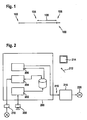
- the timing is in Fig. 1 illustrated. On a time axis 100, the point 102 marks the reaching of a stop point. After the driver has registered that the stop point has been reached, the driver performs a gear change at time 104. This is detected by the parking system and in the period 106, an automatic redirecting performed by the parking system. Thus, the vehicle is ready for the next train at time 108.
- An object of the invention is to propose a method in a parking system for assisting a parking with a longitudinal and a transverse guidance, as well as to propose such a system in which the residence time is minimized at a stop point.
- a method is proposed in a parking system for assisting parking with a longitudinal guide and a transverse guide, comprising the following steps: calculating a parking trajectory with at least one stop point; Detecting, independently of driver actions, that the calculated stop point has been reached; and providing, in response to the detection, a signal for redirecting for a steering control.
- the invention is based on the surprising finding that, at least in the case of a parking system with a longitudinal guide, the dwell time at the stop point can be minimized in a simple manner.
- a system makes it possible to detect that a calculated stop point has been reached on the basis of sensor values as they are already detected, for example for planning the parking trajectory or for other driver assistance systems.
- the sensor data may relate to, for example, an environment of the vehicle, a state of one or more wheels, the brake system, and / or a drive of the vehicle.
- a driver-initiated gear change is thus superfluous as well as the detection of any other actions of the driver, for example, a parking system affecting the operation of the driver such as a button on a mechanical button or a soft-key on a display, or an acoustic input with which a driver must initiate a parking maneuver and / or a redirection in a conventional system.
- a parking system affecting the operation of the driver such as a button on a mechanical button or a soft-key on a display, or an acoustic input with which a driver must initiate a parking maneuver and / or a redirection in a conventional system.
- the dwell time at the stop point also consists, in part, of the reaction time required by the driver to recognize that the stop point has been reached. Since, according to the invention, it is not necessary to wait for an action by the driver, the dwell time at the stop point is also shortened by this reaction time of the driver. Overall, an objectively and subjectively significant shortening of the time that the vehicle lingers at the stop point can be achieved.
- the parking trajectory may include multiple stopping points. After each detection of one of the plurality of stop points, a corresponding signal for redirecting can be provided in each case.
- the advantages of the invention are the greater, the more automatically guided trains has a parking maneuver, as reduced in a corresponding manner, the total duration of Einparkmanövers.
- the parking trajectory may include an automatically guided train immediately before and / or immediately after the stop point. If the stop point is located, for example, in the midst of a precalculated parking trajectory, the parking system can immediately detect whether the predicted stop point has been reached and can start immediately after deflection with the initiation of the next train, which further minimizes the stay time at the stop point.
- the signal for redirecting can be provided in particular before a driver-initiated gear change or other action of the driver. If the driver executes the gear change while the diverting is performed, the dwell time at the stop point is shortened. In particular, the subjective time spent at the stop point is also shortened for the driver.
- the signal for redirecting may concern a redirecting in the state. This will produce a more robust, i. achieves a more reliable and easier behavior of the parking system, to which a driver can subjectively be more confident.
- a computer program for carrying out one of the methods described here is also proposed when the computer program is executed on a programmable computer device.
- This device may be, for example, a programmable microprocessor, an application-specific integrated circuit and / or a digital signal processor with associated memory installed in a vehicle.
- At least portions of the computer program may be stored in the form of instructions on a machine-readable medium, such as a permanent or rewritable memory in or associated with a programmable computer device, or a removable CD-ROM, DVD or USB stick.
- the computer program may additionally or alternatively for downloading to a programmable computer device, for example via a data network such as the Internet or a communication connection such as a telephone connection or a wireless connection.
- a system for assisting parking with a longitudinal guide and a transverse guide which has the following components: a component for calculating a parking trajectory with at least one stop point; a component for detecting, independent of driver actions, that the calculated stop point is reached, and a component for providing, in response to the detection, a signal for redirecting for a steering control.
- the system may, for example, be a parking system that is integrated in a driver assistance system for a vehicle.
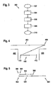
- Fig. 2 1 shows an exemplary embodiment 200 of a parking system according to the invention with a calculation device 202, a detection device 204, and a supply device 206.
- An operation of the system 200 will now be described with reference to FIG Fig. 3 indicated flowchart 300, a in Fig. 4 sketched exemplary parking trajectory 400 and an in Fig. 5 described timing described.
- the system 200 basically serves to assist a parking with a longitudinal guide and a transverse guide (302).
- Fig. 4 indicated situation is located between two pa rleklückebegrenzenden objects 402 and 404 a parking space 406, in which a not further illustrated vehicle along the trajectory 400 einparkt.
- the trajectory 400 includes stop points 408, 410, and 412, with at least points 408 and 410 also being diverted.
- the parking system 200 takes over the longitudinal and transverse guidance of the vehicle, so that the vehicle is automatically guided along trains 414 and 416. An operation of the system 200 in the vicinity of the stop or deflection point 410 will now be discussed in detail.
- the computing device 202 calculates the parking trajectory 400 with at least the trains 414 and 416 and the stop points 406 (eg, the parking assistant 200 may be activated at this point), turning point 410, and stopping point 412.
- the computing device 202 may, for example, refer to sensor data, about one in Fig. 2 schematically indicated ultrasonic sensor 208, which represent an environment of the vehicle.
- the vehicle After activation of the parking system and calculation of the trajectory 400, the vehicle is guided by the parking system 200 along the train 414 (for example, backwards) into the parking space 406.
- the detection means 204 detects that the calculated stop point 410 has been reached.
- the device 204 for example, in Fig. 2 use schematically indicated wheel sensors 210, for example, a stoppage of the vehicle to detect. Further sensor data, for example from the environmental sensor 208, and / or from sensors which, for example, detect the state of a braking and / or drive system, can likewise be processed in the device 204.
- the driver Upon reaching the stop point 410, the driver performs at least one action, namely an operation of a gear lever 212 to make a gear change at about the stop point 410 about in a forward gear.
- Other driver actions at the stop point 410 may include actuation of a button, a button, or, for example, a softkey on a display screen 214 to control the parking system or other in-vehicle (driver assistance) systems, such as in conventional systems.
- the detection means 204 detects reaching the stop point 414 independently of such or any actions of the driver, i. A detection of driver actions does not take place.
- step 308 immediately following step 306, the providing means 206 is driven by the detecting means 204 to output a signal 216 to a steering control 218 of the vehicle to cause the steering control 218 to redirect the steering 220 in preparation for the next turn 416 ,
- step 310 method 300 ends.
- a timing during the dwell time of the vehicle at the stop point 410 is in Fig. 5 illustrated.
- the representation is for the sake of comparability analogous to the representation in Fig. 1 selected.
- the point 502 indicates the time of reaching the stop point 414.
- the step 306 detection of reaching the stop point 414) and immediately thereafter, the step 308 (signal output to the steering controller 218), so that a deflection the steering 220 in the period 504 immediately after reaching the stop point 502 then takes place.
- the driver may make a gear change at about time 506, which gear change does not affect the operation of parking system 200 in steps 306 and 308.
- the redirection is completed and the vehicle is immediately ready for the next train 416.
- the parking maneuver is accelerated by the present invention working parking system 200, since the automatic parking system 200 no longer has to wait for the gear change by the driver, but initiates the redirecting immediacy after reaching the stop point. If the driver changes gear during the deflection, the vehicle is ready for the next train immediately after the deflection has been completed. Since a parking system with a longitudinal guide already has sensors for monitoring the guidance along a parking trajectory, the invention enables an acceleration of a parking maneuver in a surprisingly simple manner.
- Another advantage is the subjective shortening of the waiting time during the deflection for the driver. This can change the gear during the deflection and thus need not idle to wait for the end of the turning process.
- the inventively constructed parking system 200 can also control a deflection at the points 408 and 412, even if the feeding train is not done automatically (408) or no further train after reaching the stop point 412 more occurs.
- the parking system 200 may direct the steering for the train 414 as soon as a parking trajectory is calculated after activation of the parking system without having to wait for the driver to engage reverse gear. Rather, the driver could take the incipient deflection of the wheels as an opportunity to engage the reverse gear, so here is a sequence as in Fig. 5 outlined would result.
- the alignment of the wheels at the stop point 416 for example in a predetermined standard position, can be regarded as a comfort feature of a parking assistant.
Landscapes
- Engineering & Computer Science (AREA)
- Chemical & Material Sciences (AREA)
- Combustion & Propulsion (AREA)
- Transportation (AREA)
- Mechanical Engineering (AREA)
- Steering Control In Accordance With Driving Conditions (AREA)
- Traffic Control Systems (AREA)
- Control Of Driving Devices And Active Controlling Of Vehicle (AREA)
Description
- Die Erfindung betrifft ein Verfahren in einem Einparksystem zur Unterstützung eines Einparkens mit einer Längsführung und einer Querführung, und ein solches Einparksystem.
- Ein Einparksystem (bzw. Einparkassistent) unterstützt den Fahrer beim Einparken. Es wird beispielsweise während der Vorbeifahrt an einer Parklücke dieselbe vermessen und anschließend wird der Fahrer mittels Hinweisen in die Parklücke geführt. Das Führen in die Parklücke kann dabei in passiver Form geschehen, d.h. der Fahrer bekommt Lenkwinkelvorgaben sowie Losfahr- und Anhaltebefehle übermittelt. Der Einparkassistent kann aber das Einparken auch aktiv übernehmen, wobei der Fahrer lediglich Losfahr- bzw. Anhaltevorgaben erhält und eine Führung mindestens teilweise automatisch durch das System vorgenommen wird. Bei einer Längsführung wird das Brems- und Antriebssystem des Fahrzeugs automatisch angesteuert. Bei einer Querführung wird eine Lenksteuerung durch den Einparkassistenten automatisch angesteuert.
- Während bisher überwiegend passive oder teilautomatische Einparksysteme verfügbar sind, die entweder nur eine Längsführung oder nur eine Querführung übernehmen, steht zu erwarten, dass in Zukunft Einparksysteme mit Längs- und Querführung in Fahrzeugen vorhanden sein werden.
- Ein Einparkmanöver basiert üblicherweise auf einer berechneten Einparktrajektorie mit mindestens einem Stopppunkt, an dem ein Zugwechsel (rückwärts → vorwärts, bzw. vorwärts → rückwärts) und ein Umlenken erforderlich ist. Für Systeme mit reiner Querführung ist es bekannt, dass das Umlenken durch einen Gangwechsel des Fahrers ausgelöst wird, wie er beim Richtungswechsel zwischen zwei Zügen notwendig ist. Der zeitliche Ablauf wird in
Fig. 1 veranschaulicht. Auf einer Zeitachse 100 markiert der Punkt 102 das Erreichen eines Stopppunktes. Nachdem der Fahrer registriert hat, dass der Stopppunkt erreicht ist, führt der Fahrer zum Zeitpunkt 104 einen Gangwechsel durch. Dies wird durch das Einparksystem detektiert und im Zeitraum 106 wird ein automatisches Umlenken durch das Einparksystem durchgeführt. Somit ist das Fahrzeug zum Zeitpunkt 108 bereit für den nächsten Zug. - Es besteht ein genereller Bedarf, die für ein Einparkmanöver benötigte Einparkzeit so kurz wie möglich zu halten. So stellen Längs- wie Querparkmanöver häufig eine Behinderung für andere Verkehrsteilnehmer dar, indem eine Fahrspur blockiert und/oder ein Ausschwenken auf eine andere Fahrspur erforderlich ist. Derartige Behinderungen sollten so minimal wie möglich sein.
- Bezogen auf die in
Fig. 1 dargestellte Verweildauer an einem Stopppunkt ist anzumerken, dass viele Fahrer hierbei ungeduldig werden, weil beim assistierten Umlenken in diesem Moment für den Fahrer nichts zu tun ist. Dadurch verlängert sich auch in der subjektiven Wahrnehmung die Verweildauer am Stopppunkt. Diese Wahrnehmung verstärkt sich entsprechend bei Einparkmanövern mit mehreren Stopppunkten. - In der
US 6,059,063 wird ein automatisches Steuerungssystem für ein Fahrzeug beschrieben. Das Fahrzeug wird an einer Startposition gestoppt. Der Fahrer betätigt einen Knopf, um einen bestimmten Einparkmodus anzuwählen. Daraufhin steuert das Steuerungssystem einen Antrieb und eine Lenkung an, um einen vorgegebenen Standardlenkwinkel einzustellen. Danach wird das Fahrzeug gemäß eines vorgegebenen Standardeinparkmanövers in eine angestrebte Parkposition geführt. - Das Dokument
US 2008 154 464 A1 ist als nächstliegender Stand der Technik nach dem Oberbegriff des Anspruchs 1 zu sehen. - Eine Aufgabe der Erfindung besteht darin, ein Verfahren in einem Einparksystem zur Unterstützung eines Einparkens mit einem Längs- und einer Querführung vorzuschlagen, sowie ein derartiges System vorzuschlagen, bei dem die Verweildauer an einem Stopppunkt minimiert wird.
- Erfindungsgemäß wird ein Verfahren in einem Einparksystem zur Unterstützung eines Einparkens mit einer Längsführung und einer Querführung vorgeschlagen, welches die folgenden Schritte aufweist: Berechnen einer Einparktrajektorie mit mindestens einem Stopppunkt; Erfassen, unabhängig von Fahreraktionen, dass der berechnete Stopppunkt erreicht ist; und Bereitstellen, in Reaktion auf die Erfassung, eines Signals zum Umlenken für eine Lenksteuerung.
- Die Erfindung basiert - unter anderem - auf der überraschenden Erkenntnis, dass zumindest bei einem Einparksystem mit Längsführung die Verweildauer am Stopppunkt auf einfache Weise minimiert werden kann. Ein solches System ermöglicht das Erfassen, dass ein berechneter Stopppunkt erreicht ist, auf Basis von Sensorwerten wie sie ohnehin erfasst werden, etwa zur Planung der Einparktrajektorie oder für andere Fahrerassistenzsysteme. Die Sensordaten können etwa eine Umgebung des Fahrzeugs, einen Zustand eines oder mehrerer Räder, des Bremssystems, und/oder eines Antriebs des Fahrzeugs betreffen.
- Die Detektion eines fahrer-initiierten Gangwechsels wird dadurch ebenso überflüssig wie die Detektion beliebiger anderer Aktionen des Fahrers, bspw. einer das Einparksystem betreffenden Betätigung des Fahrers wie etwa einen Knopfdruck auf einen mechanischen Knopf oder einen Soft-Key auf einer Anzeige, oder eine akustische Eingabe, mit denen ein Fahrer in einem herkömmlichen System ein Einparkmanöver und/oder ein Umlenken initiieren muss.
- Wie aus
Fig. 1 ersichtlich, besteht die Verweildauer am Stopppunkt zu einem Teil auch aus der Reaktionszeit, die der Fahrer benötigt, um zu erkennen, dass der Stopppunkt erreicht ist. Da erfindungsgemäß nicht auf eine Aktion des Fahrers gewartet werden muss, verkürzt sich die Verweildauer am Stopppunkt auch um diese Reaktionszeit des Fahrers. Insgesamt kann so eine objektiv wie subjektiv deutliche Verkürzung der Zeit erreicht werden, die das Fahrzeug am Stopppunkt verweilt. - Da auf eine Detektion von Fahreraktionen verzichtet wird, vereinfacht sich das erfindungsgemäße Einparksystem im Vergleich zu herkömmlichen Systemen. Die Einparktrajektorie kann mehrere Stopppunkte umfassen. Nach jedem Erfassen eines der mehreren Stopppunkte kann jeweils ein entsprechendes Signal zum Umlenken bereitgestellt werden. Die Vorteile der Erfindung werden umso größer, je mehr automatisch geführte Züge ein Einparkmanöver aufweist, da sich in entsprechender Weise die Gesamtdauer des Einparkmanövers verringert.
- Die Einparktrajektorie kann einen automatisch geführten Zug unmittelbar vor und/oder unmittelbar nach dem Stopppunkt umfassen. Befindet sich der Stopppunkt bspw. inmitten in einer vorausberechneten Einparktrajektorie, kann das Einparksystem unmittelbar erfassen, ob der vorausberechnete Stopppunkt erreicht wurde, und kann unmittelbar nach erfolgtem Umlenken mit der Einleitung des nächsten Zuges beginnen, was die Verweildauer am Stopppunkt nochmals minimiert.
- Das Signal zum Umlenken kann insbesondere vor einem fahrer-initiierten Gangwechsel oder einer sonstigen Aktion des Fahrers bereitgestellt werden. Führt der Fahrer den Gangwechsel aus, während das Umlenken vollzogen wird, verkürzt sich die Verweildauer am Stopppunkt. Insbesondere verkürzt sich auch die subjektive am Stopppunkt verbrachte Zeit für den Fahrer.
- Das Signal zum Umlenken kann ein Umlenken im Stand betreffen. Hierdurch wird ein robusteres, d.h. zuverlässigeres und einfacheres Verhalten des Einparksystems erzielt, dem ein Fahrer auch subjektiv mehr Vertrauen entgegenbringen kann.
- Erfindungsgemäß wird weiterhin ein Computerprogramm zur Durchführung eines der hier beschriebenen Verfahren vorgeschlagen, wenn das Computerprogramm auf einer programmierbaren Computereinrichtung ausgeführt wird. Bei dieser Einrichtung kann es sich beispielsweise um einen programmierbaren Mikroprozessor, eine anwendungsspezifische, integrierte Schaltung und/oder einen digitalen Signalprozessor mit zugeordnetem Speicher handeln, der in einem Fahrzeug eingebaut ist. Zumindest Teile des Computerprogramms können in Form von folgen von Instruktionen auf einem maschinenlesbaren Datenträger gespeichert sein, etwa einem permanenten oder wiederbeschreibbaren Speicher in oder in Zuordnung zu einer programmierbaren Computereinrichtung, oder einer entfernbaren CD-ROM, DVD oder einem USB-Stick. Das Computerprogramm kann zusätzlich oder alternativ auch zum Herunterladen auf eine programmierbare Computereinrichtung vorgesehen sein, zum Beispiel über ein Datennetzwerk wie etwa das Internet oder eine Kommunikationsverbindung wie etwa eine Telefonverbindung oder eine drahtlose Verbindung.
- Erfindungsgemäß wird weiterhin ein System zur Unterstützung eines Einparkens mit einer Längsführung und einer Querführung vorgeschlagen, welches die folgenden Komponenten aufweist: eine Komponente zum Berechnen einer Einparktrajektorie mit mindestens einem Stopppunkt; eine Komponente zum Erfassen, unabhängig von Fahreraktionen, dass der berechnete Stopppunkt erreicht ist, und eine Komponente zum Bereitstellen, in Reaktion auf die Erfassung, eines Signals zum Umlenken für eine Lenksteuerung. Bei dem System kann es sich beispielsweise um ein Einparksystem handelt, welches in ein Fahrerassistenzsystem für ein Fahrzeug integriert ist.
- Weitere Aspekte und Vorteile der Erfindung werden nunmehr anhand der beigefügten Figuren eingehender beschrieben. Hierbei zeigt:
- Fig. 1
- eine schematische Illustration einer Verweildauer an einem Stopppunkt bei einem herkömmlichen Einparksystem;
- Fig. 2
- in Form eines Blockschaltbildes funktionale Komponenten eines erfindungsgemäßen Einparksystems;
- Fig. 3
- in Form eines Flussdiagramms eine Arbeitsweise des Einparksystems der
Fig. 2 ; - Fig. 4
- in schematischer Form eine Einparktrajektorie zur weiteren Veranschaulichung der Arbeitsweise des Einparksystems der
Fig. 2 ; und - Fig. 5
- eine Illustration der Verweildauer an einem Stopppunkt bei dem erfindungsgemäßen Einparksystem der
Fig. 2 . -
Fig. 2 zeigt ein Ausführungsbeispiel 200 eines efindungsgemäßen Einparksystems mit einer Berechnungseinrichtung 202, einer Erfassungseinrichtung 204, und eine Bereitstellungseinrichtung 206. Eine Arbeitsweise des Systems 200 wird nunmehr unter Bezugnahme auf das inFig. 3 angedeutete Ablaufdiagramm 300, eine inFig. 4 skizzierte beispielhafte Einparktrajektorie 400 und einen inFig. 5 dargestellten zeitlichen Ablauf beschrieben. Das System 200 dient grundsätzlich zur Unterstützung eines Einparkens mit einer Längsführung und einer Querführung (302). - Gemäß der in
Fig. 4 angedeuteten Situation befindet sich zwischen zwei pa rklückenbegrenzenden Objekten 402 und 404 eine Parklücke 406, in die ein nicht weiter dargestelltes Fahrzeug entlang der Trajektorie 400 einparkt. Die Trajektorie 400 enthält Stopppunkte 408, 410 und 412, wobei wenigstens an den Punkten 408 und 410 auch umzulenken ist. Spätestens ab dem Punkt 408 übernimmt das Einparksystem 200 die Längs- sowie Querführung des Fahrzeugs, so dass das Fahrzeug entlang von Zügen 414 und 416 automatisch geführt wird. Auf eine Arbeitsweise des Systems 200 in der Umgebung des Stopp- bzw. Umlenkpunktes 410 wird nunmehr besonders eingegangen. - In Schritt 304 berechnet die Berechnungseinrichtung 202 die Einparktrajektorie 400 mit wenigstens den Zügen 414 und 416 sowie den Stopppunkten 406 (bspw. kann der Einparkassistent 200 an diesem Punkt aktiviert werden), Umlenkpunkt 410 und Stopppunkt 412. Die Berechnungseinrichtung 202 kann hierzu beispielsweise auf Sensordaten, etwa eines in
Fig. 2 schematisch angedeuteten Ultraschallsensors 208, zurückgreifen, die eine Umgebung des Fahrzeugs repräsentieren. - Nach Aktivierung des Einparksystems und Berechnung der Trajektorie 400 wird das Fahrzeug vom Einparksystem 200 entlang des Zuges 414 (zum Beispiel rückwärts) in die Parklücke 406 hineingeführt. In Schritt 306 erfasst die Erfassungseinrichtung 204, dass der berechnete Stopppunkt 410 erreicht ist. Hierzu kann die Einrichtung 204 beispielsweise auf in
Fig. 2 schematisch angedeutete Radsensoren 210 zurückgreifen, um beispielsweise einen Stillstand des Fahrzeugs zu detektieren. Weitere Sensordaten, zum Beispiel vom Umgebungssensor 208, und/oder von Sensoren, die bspw. den Zustand eines Brems- und/oder Antriebssystems erfassen, können ebenfalls in der Einrichtung 204 verarbeitet werden. - Bei Erreichen des Stopppunktes 410 führt der Fahrer mindestens eine Aktion durch, nämlich eine Betätigung eines Ganghebels 212, um am Stopppunkt 410 einen Gangwechsel etwa in einen Vorwärtsgang vorzunehmen. Weitere Fahreraktionen am Stopppunkt 410 könnten etwa gemäß herkömmlicher Systeme die Betätigung eines Knopfes, einer Taste, oder beispielsweise eines Soft-Keys auf einem Anzeigeschirm 214 zur Steuerung des Einparksystems oder anderer im Fahrzeug befindlicher (Fahrerassistenz-)Systeme umfassen. Die Erfassungseinrichtung 204 erfasst jedoch das Erreichen des Stopppunktes 414 unabhängig von solchen oder beliebigen Aktionen des Fahrers, d.h. eine Detektierung von Fahreraktionen findet nicht statt.
- In Schritt 308, der unmittelbar auf den Schritt 306 folgt, wird die Bereitstellungseinrichtung 206 von der Erfassungseinrichtung 204 angesteuert, um ein Signal 216 an eine Lenksteuerung 218 des Fahrzeugs auszugeben, damit die Lenksteuerung 218 ein Umlenken der Lenkung 220 in Vorbereitung des nächsten Zuges 416 durchführt. Mit Schritt 310 endet das Verfahren 300.
- Eine zeitlicher Ablauf während der Verweildauer des Fahrzeugs am Stopppunkt 410 ist in
Fig. 5 veranschaulicht. Die Darstellung ist der Vergleichbarkeit halber analog zur Darstellung inFig. 1 gewählt. Auf einer Zeitachse 500 bezeichnet der Punkt 502 den Zeitpunkt des Erreichens des Stopppunktes 414. Zu diesem Zeitpunkt läuft der Schritt 306 (Erfassen des Erreichens des Stopppunktes 414) und unmittelbar danach der Schritt 308 (Signalausgabe an die Lenksteuerung 218) ab, so dass ein Umlenken der Lenkung 220 im Zeitraum 504 unmittelbar an das Erreichen des Stopppunktes 502 anschließend erfolgt. Während des Umlenkens im Zeitraum 504 kann der Fahrer etwa zum Zeitpunkt 506 einen Gangwechsel durchführen, wobei dieser Gangwechsel sich nicht auf die Arbeitsweise des Einparksystems 200 in den Schritten 306 und 308 auswirkt. Zum Zeitpunkt 508 ist das Umlenken beendet und das Fahrzeug ist unmittelbar bereit für den nächsten Zug 416. - Wie aus einem Vergleich der
Figur 5 mit derFigur 1 unmittelbar hervorgeht, wird das Einparkmanöver durch das erfindungsgemäß arbeitende Einparksystem 200 beschleunigt, da das automatische Einparksystem 200 nicht mehr auf den Gangwechsel durch den Fahrer warten muss, sondern das Umlenken ummittelbar nach Erreichen des Stopppunktes einleitet. Wechselt der Fahrer während des Umlenkens den Gang, ist das Fahrzeug unmittelbar nach Beendigung des Umlenkens bereit für den nächsten Zug. Da ein Einparksystem mit Längsführung bereits über Sensorik zur Überwachung der Führung entlang einer Einparktrajektorie verfügt, ermöglicht die Erfindung hier auf überraschend einfache Weise eine Beschleunigung eines Einparkmanövers. - Als weiterer Vorteil ist die subjektive Verkürzung der Wartezeit während des Umlenkens für den Fahrer anzusehen. Dieser kann während des Umlenkens den Gang wechseln und braucht somit nicht untätig auf das Ende des Umlenkvorgangs zu warten.
- Die oben beschriebenen Vorteile wirken sich entsprechend stärker bei Einparktrajektorien mit mehreren Stopp- und/oder Umlenkpunkten aus. Unter erneutem Bezug auf das in den
Figuren 2 - 5 dargestellte Ausführungsbeispiel wird darauf hingewiesen, dass das erfindungsgemäß ausgebildete Einparksystem 200 auch ein Umlenken an den Punkten 408 und 412 steuern kann, auch wenn hier der zuführende Zug nicht automatisch erfolgt (408) bzw. kein weiterer Zug nach Erreichen des Stopppunktes 412 mehr erfolgt. Am Punkt 408 kann das Einparksystem 200 die Lenkung für den Zug 414 ausrichten, sobald nach Aktivierung des Einparksystems eine Einparktrajektorie berechnet ist, ohne auf das Einlegen des Rückwärtsganges durch den Fahrer warten zu müssen. Vielmehr könnte der Fahrer das beginnende Umlenken der Räder zum Anlass nehmen, den Rückwärtsgang einzulegen, so das sich auch hier ein Ablauf wie inFig. 5 skizziert ergeben würde. Das Ausrichten der Räder im Stopppunkt 416, bspw. in eine vorgegebene Standardposition, kann als ein Komfortmerkmal eines Einparkassistenten angesehen werden. - Die Erfindung ist nicht auf die hier beschriebenen Ausführungsbeispiele und die darin hervorgehobenen Aspekte beschränkt; vielmehr sind innerhalb des durch die anhängenden Ansprüche angegebenen Bereichs eine Vielzahl von Abwandlungen möglich, die im Rahmen fachmännischen Handelns liegen.
Claims (7)
- Verfahren in einem Einparksystem zur Unterstützung eines Einparkens mit einer Längsführung und einer Querführung, mit den folgenden Schritten:- Berechnen (304) einer Einparktrajektorie (400) mit mindestens einem Stopppunkt (410);- Erfassen (306), unabhängig von Fahreraktionen, dass der berechnete Stopppunkt (410) erreicht ist; und- Bereitstellen (308), in Reaktion auf die Erfassung, eines Signals (216) zum Umlenken für eine Lenksteuerung (218),
dadurch gekennzeichnet, dass das Signal (216) zum Umlenken vor (502) einem fahrer-initiierten Gangwechsel (508) bereitgestellt wird. - Verfahren nach Anspruch 1,
dadurch gekennzeichnet, dass
die Einparktrajektorie (400) einen automatisch geführten Zug unmittelbar vor (414) und/oder unmittelbar nach dem Stopppunkt (416) umfasst. - Verfahren nach Anspruch 1 oder 2,
dadurch gekennzeichnet, dass
die Einparktrajektorie mehrere Stopppunkte umfasst und nach jedem Erfassen eines der mehreren Stopppunkte ein entsprechendes Signal zum Umlenken bereitgestellt wird. - Verfahren nach einem der vorhergehenden Ansprüche,
dadurch gekennzeichnet, dass
das Erfassen insbesondere unabhängig von einem fahrer-initiierten Gangwechsel und/oder einer das Einparksystem betreffenden Betätigung des Fahrers erfolgt. - Verfahren nach einem der vorhergehenden Ansprüche,
dadurch gekennzeichnet, dass
das Signal zum Umlenken (216) ein Umlenken im Stand betrifft. - Computerprogramm zur Durchführung des Verfahrens nach einem der vorhergehenden Ansprüche, wenn das Computerprogramm auf einer programmierbaren Computereinrichtung ausgeführt wird.
- Maschinenlesbarer Datenträger, auf dem Instruktionen zur Durchführung eines Verfahrens nach einem der Ansprüche 1 bis 5 gespeichert sind, wenn die Instruktionen von einer Computereinrichtung ausgeführt werden.
Applications Claiming Priority (2)
| Application Number | Priority Date | Filing Date | Title |
|---|---|---|---|
| DE102010028330A DE102010028330A1 (de) | 2010-04-28 | 2010-04-28 | Einparksystemen mit Längs- und Querführung |
| PCT/EP2011/056218 WO2011134843A1 (de) | 2010-04-28 | 2011-04-19 | Einparksystemen mit längs- und querführung |
Publications (2)
| Publication Number | Publication Date |
|---|---|
| EP2563640A1 EP2563640A1 (de) | 2013-03-06 |
| EP2563640B1 true EP2563640B1 (de) | 2014-04-02 |
Family
ID=44170399
Family Applications (1)
| Application Number | Title | Priority Date | Filing Date |
|---|---|---|---|
| EP11716872.4A Active EP2563640B1 (de) | 2010-04-28 | 2011-04-19 | Einparksystemen mit längs- und querführung |
Country Status (6)
| Country | Link |
|---|---|
| US (1) | US20130103246A1 (de) |
| EP (1) | EP2563640B1 (de) |
| JP (1) | JP2013525192A (de) |
| CN (1) | CN102883937B (de) |
| DE (1) | DE102010028330A1 (de) |
| WO (1) | WO2011134843A1 (de) |
Families Citing this family (12)
| Publication number | Priority date | Publication date | Assignee | Title |
|---|---|---|---|---|
| DE102010028330A1 (de) * | 2010-04-28 | 2011-11-03 | Robert Bosch Gmbh | Einparksystemen mit Längs- und Querführung |
| DE102013214764B4 (de) * | 2013-07-29 | 2020-03-19 | Bayerische Motoren Werke Aktiengesellschaft | Durchführen eines Fahrtrichtungswechsels bei einem Parkassistenzsystem mit Längs- und Querführung |
| US9751558B2 (en) | 2015-03-25 | 2017-09-05 | Ford Global Technologies, Llc | Handwheel obstruction detection and inertia compensation |
| US9616928B2 (en) | 2015-03-25 | 2017-04-11 | Ford Global Technologies, Llc | Steering angle control for multiple features |
| US10214206B2 (en) * | 2015-07-13 | 2019-02-26 | Magna Electronics Inc. | Parking assist system for vehicle |
| US9849864B2 (en) | 2015-07-31 | 2017-12-26 | Ford Global Technologies, Llc | Vehicle parking assist system |
| US10328933B2 (en) | 2015-10-29 | 2019-06-25 | Ford Global Technologies, Llc | Cognitive reverse speed limiting |
| US9895945B2 (en) | 2015-12-08 | 2018-02-20 | Ford Global Technologies, Llc | Trailer backup assist system with hitch assist |
| US9829883B1 (en) | 2016-10-17 | 2017-11-28 | Ford Global Technologies, Llc | Trailer backup assist system having remote control and user sight management |
| CN113850313B (zh) * | 2021-09-18 | 2025-11-11 | 上海万位科技有限公司 | 一种基于大数据的车辆转弯停留事件检测方法、设备 |
| US12252172B2 (en) | 2021-09-21 | 2025-03-18 | Magna Electronics Inc. | Vehicular intelligent remote parking assist system |
| DE102023114408A1 (de) | 2023-06-01 | 2024-12-05 | Bayerische Motoren Werke Aktiengesellschaft | Verfahren und Fahrsystem zur Durchführung eines Fahrtrichtungswechsels |
Family Cites Families (23)
| Publication number | Priority date | Publication date | Assignee | Title |
|---|---|---|---|---|
| JPS61263851A (ja) * | 1985-05-17 | 1986-11-21 | Nippon Denso Co Ltd | 自動車の自動幅寄せ装置 |
| JP3396893B2 (ja) * | 1992-05-25 | 2003-04-14 | 株式会社デンソー | 車両の車庫誘導装置 |
| DE19632929C1 (de) * | 1996-08-16 | 1997-11-27 | Daimler Benz Ag | Vorrichtung zur selbsttätigen Fahrzeugquerführung längs einer Fahrspur |
| JP3044534B2 (ja) | 1997-04-28 | 2000-05-22 | 本田技研工業株式会社 | 車両の自動操舵装置 |
| JP3266828B2 (ja) * | 1997-07-16 | 2002-03-18 | 本田技研工業株式会社 | 車両の自動操舵装置 |
| DE19841914A1 (de) * | 1998-09-14 | 2000-03-16 | Bosch Gmbh Robert | Automatisches Lenksystem |
| JP2002172988A (ja) * | 2000-12-05 | 2002-06-18 | Mitsubishi Motors Corp | 駐車補助装置 |
| CN2700163Y (zh) * | 2003-12-09 | 2005-05-18 | 比亚迪股份有限公司 | 自动泊车系统 |
| JP2005313710A (ja) * | 2004-04-27 | 2005-11-10 | Toyota Motor Corp | 駐車支援装置 |
| JP4389650B2 (ja) * | 2004-04-28 | 2009-12-24 | 三菱自動車工業株式会社 | 自動操舵駐車支援装置 |
| CN100535598C (zh) * | 2004-08-20 | 2009-09-02 | 爱信精机株式会社 | 用于车辆的停车辅助装置及停车辅助方法 |
| JP4283199B2 (ja) * | 2004-10-07 | 2009-06-24 | 本田技研工業株式会社 | 車両の操舵制御装置 |
| DE102005027165B4 (de) * | 2005-06-13 | 2024-01-25 | Robert Bosch Gmbh | Verfahren und Vorrichtung zur Ausgabe von Einparkhinweisen |
| JP4572752B2 (ja) * | 2005-06-17 | 2010-11-04 | トヨタ自動車株式会社 | 走行支援装置 |
| DE102005037468A1 (de) * | 2005-08-09 | 2007-02-15 | Robert Bosch Gmbh | Vorrichtung und Verfahren zur Unterstützung eines Einparkvorgangs eines Fahrzeugs |
| JP2007176324A (ja) * | 2005-12-28 | 2007-07-12 | Aisin Seiki Co Ltd | 駐車支援装置 |
| DE102006026092A1 (de) * | 2006-06-03 | 2007-12-06 | Bayerische Motoren Werke Ag | Verfahren zur Steuerung eines Einparkvorgangs |
| US20080154464A1 (en) * | 2006-12-26 | 2008-06-26 | Honda Motor Co., Ltd. | Automatic Parking control apparatus for vehicle |
| CN101573257B (zh) * | 2006-12-28 | 2011-08-10 | 株式会社丰田自动织机 | 停车辅助装置及方法、行车参数的计算方法及装置 |
| DE102007029773A1 (de) * | 2007-06-22 | 2008-12-24 | Volkswagen Ag | Parklenkassistenzsystem und Verfahren zum Unterstützen eines Ausparkvorgangs |
| US7737866B2 (en) * | 2007-09-27 | 2010-06-15 | Automotive Research & Testing Center | Auto-parking device |
| DE102008041681A1 (de) * | 2008-08-29 | 2010-03-04 | Robert Bosch Gmbh | Steuereinrichtung und Verfahren zur Durchführung eines automatischen Einparkvorgangs |
| DE102010028330A1 (de) * | 2010-04-28 | 2011-11-03 | Robert Bosch Gmbh | Einparksystemen mit Längs- und Querführung |
-
2010
- 2010-04-28 DE DE102010028330A patent/DE102010028330A1/de not_active Withdrawn
-
2011
- 2011-04-19 US US13/643,856 patent/US20130103246A1/en not_active Abandoned
- 2011-04-19 JP JP2013506587A patent/JP2013525192A/ja active Pending
- 2011-04-19 CN CN201180021011.2A patent/CN102883937B/zh active Active
- 2011-04-19 EP EP11716872.4A patent/EP2563640B1/de active Active
- 2011-04-19 WO PCT/EP2011/056218 patent/WO2011134843A1/de not_active Ceased
Also Published As
| Publication number | Publication date |
|---|---|
| CN102883937A (zh) | 2013-01-16 |
| DE102010028330A1 (de) | 2011-11-03 |
| CN102883937B (zh) | 2016-11-09 |
| EP2563640A1 (de) | 2013-03-06 |
| WO2011134843A1 (de) | 2011-11-03 |
| US20130103246A1 (en) | 2013-04-25 |
| JP2013525192A (ja) | 2013-06-20 |
Similar Documents
| Publication | Publication Date | Title |
|---|---|---|
| EP2563640A1 (de) | Einparksystemen mit längs- und querführung | |
| EP2780213B1 (de) | Verfahren und vorrichtung zum bestimmen einer ausparkstrategie | |
| EP3261903B1 (de) | Parkassistenzsystem mit erkennung einer universalparklücke | |
| EP3803526B1 (de) | Trainingsverfahren für ein fahrerassistenzverfahren, fahrerassistenzverfahren, steuergerät und fahrzeug mit dem steuergerät | |
| EP3512754B1 (de) | Vorrichtung, betriebsverfahren und elektronische steuereinheit zur steuerung eines zumindest teilweise automatisiert fahrbaren fahrzeugs | |
| EP2576324B1 (de) | Verfahren und vorrichtung zum unterstützten parken eines kraftfahrzeugs | |
| EP3177504B1 (de) | Verfahren zum zumindest semi-autonomen manövrieren eines kraftfahrzeugs, fahrerassistenzsystem sowie kraftfahrzeug | |
| EP2429872B1 (de) | Verfahren und vorrichtung zur einparkunterstützung eines fahrzeugs | |
| EP3479183B2 (de) | Verfahren zum betrieb eines kraftfahrzeugs in einer navigationsumgebung und kraftfahrzeug | |
| EP4422943B1 (de) | Verfahren zum unterstützen eines nutzers eines fahrzeugs beim manövrieren des fahrzeugs auf einer mehrspurigen strasse unter berücksichtigung einer individuellen reaktionszeit des nutzers, fahrerassistenzsystem sowie fahrzeug | |
| EP2008915A2 (de) | Vorrichtung zur semiautonomen Unterstützung der Lenkbewegung eines Fahrzeuges | |
| DE102014115334B4 (de) | Verfahren zum Unterstützen eines Fahrers eines Kraftfahrzeugs beim Einparken in eine Parklücke, Fahrerassistenzsystem sowie Kraftfahrzeug | |
| EP2159121B1 (de) | Steuereinrichtung und Verfahren zur Durchführung eines automatischen Einparkvorgangs | |
| DE102010049585A1 (de) | Verfahren zur Unterstützung eines Fahrzeugführers eines Fahrzeugs bei einem Parkmanöver und Vorrichtung zur Durchführung des Verfahrens | |
| EP4412881B1 (de) | Verfahren zum manövrieren eines fahrzeugs auf einer mehrspurigen strasse unter berücksichtigung einer steigung in einem bereich einer ausfahrt der strasse, fahrerassistenzsystem sowie fahrzeug | |
| EP2993111B1 (de) | Verfahren zum unterstützen eines fahrers eines kraftfahrzeugs beim einparken, fahrerassistenzsystem sowie kraftfahrzeug | |
| EP3121095A1 (de) | Verfahren und vorrichtung zur fahrerassistenz | |
| DE102010022716A1 (de) | Verfahren und Vorrichtung zum unterstützten Parken eines Kraftfahrzeugs | |
| DE102017210173A1 (de) | Trajektorienbasiertes Führen eines Kraftfahrzeugs | |
| EP2886422A2 (de) | Verfahren zum Bestimmen eines aktuellen Lenkwinkels eines Kraftfahrzeugs, Fahrerassistenzeinrichtung und Kraftfahrzeug | |
| DE102015216101A1 (de) | Automatisches Fahren eines Gespanns | |
| WO2015117611A2 (de) | Verfahren und vorrichtung zum sicheren parken eines fahrzeugs | |
| EP1872997A1 (de) | Kraftfahrzeug umfassend wenigstens ein den Abstand zu einem vorausfahrenden Fahrzeug erfassendes Abstandswarnsystem, insbesondere ein Längsführungssystem | |
| DE102018131598A1 (de) | Parkassistenzsystem und Verfahren zum automatisierten Ausparken nach einem manuellen Einparkvorgang | |
| DE102016120677A1 (de) | Verfahren zum Betreiben eines Fahrerassistenzsystems zum Durchführen eines zumindest semi-autonomen Einparkmanövers eines Kraftfahrzeugs unter Berücksichtigung von Eingriffen des Fahrers, Fahrerassistenzsystem sowie Kraftfahrzeug |
Legal Events
| Date | Code | Title | Description |
|---|---|---|---|
| PUAI | Public reference made under article 153(3) epc to a published international application that has entered the european phase |
Free format text: ORIGINAL CODE: 0009012 |
|
| 17P | Request for examination filed |
Effective date: 20121128 |
|
| AK | Designated contracting states |
Kind code of ref document: A1 Designated state(s): AL AT BE BG CH CY CZ DE DK EE ES FI FR GB GR HR HU IE IS IT LI LT LU LV MC MK MT NL NO PL PT RO RS SE SI SK SM TR |
|
| DAX | Request for extension of the european patent (deleted) | ||
| GRAP | Despatch of communication of intention to grant a patent |
Free format text: ORIGINAL CODE: EPIDOSNIGR1 |
|
| INTG | Intention to grant announced |
Effective date: 20131202 |
|
| GRAP | Despatch of communication of intention to grant a patent |
Free format text: ORIGINAL CODE: EPIDOSNIGR1 |
|
| GRAS | Grant fee paid |
Free format text: ORIGINAL CODE: EPIDOSNIGR3 |
|
| GRAA | (expected) grant |
Free format text: ORIGINAL CODE: 0009210 |
|
| INTG | Intention to grant announced |
Effective date: 20140204 |
|
| AK | Designated contracting states |
Kind code of ref document: B1 Designated state(s): AL AT BE BG CH CY CZ DE DK EE ES FI FR GB GR HR HU IE IS IT LI LT LU LV MC MK MT NL NO PL PT RO RS SE SI SK SM TR |
|
| REG | Reference to a national code |
Ref country code: GB Ref legal event code: FG4D Free format text: NOT ENGLISH |
|
| REG | Reference to a national code |
Ref country code: CH Ref legal event code: EP Ref country code: AT Ref legal event code: REF Ref document number: 659906 Country of ref document: AT Kind code of ref document: T Effective date: 20140415 |
|
| REG | Reference to a national code |
Ref country code: IE Ref legal event code: FG4D Free format text: LANGUAGE OF EP DOCUMENT: GERMAN |
|
| REG | Reference to a national code |
Ref country code: DE Ref legal event code: R096 Ref document number: 502011002610 Country of ref document: DE Effective date: 20140515 |
|
| REG | Reference to a national code |
Ref country code: NL Ref legal event code: VDEP Effective date: 20140402 |
|
| REG | Reference to a national code |
Ref country code: LT Ref legal event code: MG4D |
|
| PG25 | Lapsed in a contracting state [announced via postgrant information from national office to epo] |
Ref country code: NL Free format text: LAPSE BECAUSE OF FAILURE TO SUBMIT A TRANSLATION OF THE DESCRIPTION OR TO PAY THE FEE WITHIN THE PRESCRIBED TIME-LIMIT Effective date: 20140402 Ref country code: NO Free format text: LAPSE BECAUSE OF FAILURE TO SUBMIT A TRANSLATION OF THE DESCRIPTION OR TO PAY THE FEE WITHIN THE PRESCRIBED TIME-LIMIT Effective date: 20140702 Ref country code: IS Free format text: LAPSE BECAUSE OF FAILURE TO SUBMIT A TRANSLATION OF THE DESCRIPTION OR TO PAY THE FEE WITHIN THE PRESCRIBED TIME-LIMIT Effective date: 20140802 Ref country code: CZ Free format text: LAPSE BECAUSE OF FAILURE TO SUBMIT A TRANSLATION OF THE DESCRIPTION OR TO PAY THE FEE WITHIN THE PRESCRIBED TIME-LIMIT Effective date: 20140402 Ref country code: CY Free format text: LAPSE BECAUSE OF FAILURE TO SUBMIT A TRANSLATION OF THE DESCRIPTION OR TO PAY THE FEE WITHIN THE PRESCRIBED TIME-LIMIT Effective date: 20140402 Ref country code: LT Free format text: LAPSE BECAUSE OF FAILURE TO SUBMIT A TRANSLATION OF THE DESCRIPTION OR TO PAY THE FEE WITHIN THE PRESCRIBED TIME-LIMIT Effective date: 20140402 Ref country code: GR Free format text: LAPSE BECAUSE OF FAILURE TO SUBMIT A TRANSLATION OF THE DESCRIPTION OR TO PAY THE FEE WITHIN THE PRESCRIBED TIME-LIMIT Effective date: 20140703 Ref country code: FI Free format text: LAPSE BECAUSE OF FAILURE TO SUBMIT A TRANSLATION OF THE DESCRIPTION OR TO PAY THE FEE WITHIN THE PRESCRIBED TIME-LIMIT Effective date: 20140402 Ref country code: BG Free format text: LAPSE BECAUSE OF FAILURE TO SUBMIT A TRANSLATION OF THE DESCRIPTION OR TO PAY THE FEE WITHIN THE PRESCRIBED TIME-LIMIT Effective date: 20140702 |
|
| PG25 | Lapsed in a contracting state [announced via postgrant information from national office to epo] |
Ref country code: PL Free format text: LAPSE BECAUSE OF FAILURE TO SUBMIT A TRANSLATION OF THE DESCRIPTION OR TO PAY THE FEE WITHIN THE PRESCRIBED TIME-LIMIT Effective date: 20140402 Ref country code: ES Free format text: LAPSE BECAUSE OF FAILURE TO SUBMIT A TRANSLATION OF THE DESCRIPTION OR TO PAY THE FEE WITHIN THE PRESCRIBED TIME-LIMIT Effective date: 20140402 Ref country code: HR Free format text: LAPSE BECAUSE OF FAILURE TO SUBMIT A TRANSLATION OF THE DESCRIPTION OR TO PAY THE FEE WITHIN THE PRESCRIBED TIME-LIMIT Effective date: 20140402 Ref country code: SE Free format text: LAPSE BECAUSE OF FAILURE TO SUBMIT A TRANSLATION OF THE DESCRIPTION OR TO PAY THE FEE WITHIN THE PRESCRIBED TIME-LIMIT Effective date: 20140402 Ref country code: LV Free format text: LAPSE BECAUSE OF FAILURE TO SUBMIT A TRANSLATION OF THE DESCRIPTION OR TO PAY THE FEE WITHIN THE PRESCRIBED TIME-LIMIT Effective date: 20140402 Ref country code: RS Free format text: LAPSE BECAUSE OF FAILURE TO SUBMIT A TRANSLATION OF THE DESCRIPTION OR TO PAY THE FEE WITHIN THE PRESCRIBED TIME-LIMIT Effective date: 20140402 |
|
| REG | Reference to a national code |
Ref country code: CH Ref legal event code: PL |
|
| PG25 | Lapsed in a contracting state [announced via postgrant information from national office to epo] |
Ref country code: PT Free format text: LAPSE BECAUSE OF FAILURE TO SUBMIT A TRANSLATION OF THE DESCRIPTION OR TO PAY THE FEE WITHIN THE PRESCRIBED TIME-LIMIT Effective date: 20140804 |
|
| REG | Reference to a national code |
Ref country code: DE Ref legal event code: R097 Ref document number: 502011002610 Country of ref document: DE |
|
| REG | Reference to a national code |
Ref country code: IE Ref legal event code: MM4A |
|
| PG25 | Lapsed in a contracting state [announced via postgrant information from national office to epo] |
Ref country code: MC Free format text: LAPSE BECAUSE OF FAILURE TO SUBMIT A TRANSLATION OF THE DESCRIPTION OR TO PAY THE FEE WITHIN THE PRESCRIBED TIME-LIMIT Effective date: 20140402 Ref country code: SK Free format text: LAPSE BECAUSE OF FAILURE TO SUBMIT A TRANSLATION OF THE DESCRIPTION OR TO PAY THE FEE WITHIN THE PRESCRIBED TIME-LIMIT Effective date: 20140402 Ref country code: RO Free format text: LAPSE BECAUSE OF FAILURE TO SUBMIT A TRANSLATION OF THE DESCRIPTION OR TO PAY THE FEE WITHIN THE PRESCRIBED TIME-LIMIT Effective date: 20140402 Ref country code: DK Free format text: LAPSE BECAUSE OF FAILURE TO SUBMIT A TRANSLATION OF THE DESCRIPTION OR TO PAY THE FEE WITHIN THE PRESCRIBED TIME-LIMIT Effective date: 20140402 Ref country code: LI Free format text: LAPSE BECAUSE OF NON-PAYMENT OF DUE FEES Effective date: 20140430 Ref country code: CH Free format text: LAPSE BECAUSE OF NON-PAYMENT OF DUE FEES Effective date: 20140430 Ref country code: EE Free format text: LAPSE BECAUSE OF FAILURE TO SUBMIT A TRANSLATION OF THE DESCRIPTION OR TO PAY THE FEE WITHIN THE PRESCRIBED TIME-LIMIT Effective date: 20140402 |
|
| PLBE | No opposition filed within time limit |
Free format text: ORIGINAL CODE: 0009261 |
|
| STAA | Information on the status of an ep patent application or granted ep patent |
Free format text: STATUS: NO OPPOSITION FILED WITHIN TIME LIMIT |
|
| 26N | No opposition filed |
Effective date: 20150106 |
|
| PG25 | Lapsed in a contracting state [announced via postgrant information from national office to epo] |
Ref country code: IT Free format text: LAPSE BECAUSE OF FAILURE TO SUBMIT A TRANSLATION OF THE DESCRIPTION OR TO PAY THE FEE WITHIN THE PRESCRIBED TIME-LIMIT Effective date: 20140402 |
|
| REG | Reference to a national code |
Ref country code: DE Ref legal event code: R097 Ref document number: 502011002610 Country of ref document: DE Effective date: 20150106 |
|
| PG25 | Lapsed in a contracting state [announced via postgrant information from national office to epo] |
Ref country code: IE Free format text: LAPSE BECAUSE OF NON-PAYMENT OF DUE FEES Effective date: 20140419 |
|
| PG25 | Lapsed in a contracting state [announced via postgrant information from national office to epo] |
Ref country code: RS Free format text: LAPSE BECAUSE OF FAILURE TO SUBMIT A TRANSLATION OF THE DESCRIPTION OR TO PAY THE FEE WITHIN THE PRESCRIBED TIME-LIMIT Effective date: 20141119 |
|
| PG25 | Lapsed in a contracting state [announced via postgrant information from national office to epo] |
Ref country code: SI Free format text: LAPSE BECAUSE OF FAILURE TO SUBMIT A TRANSLATION OF THE DESCRIPTION OR TO PAY THE FEE WITHIN THE PRESCRIBED TIME-LIMIT Effective date: 20140402 |
|
| PG25 | Lapsed in a contracting state [announced via postgrant information from national office to epo] |
Ref country code: MT Free format text: LAPSE BECAUSE OF FAILURE TO SUBMIT A TRANSLATION OF THE DESCRIPTION OR TO PAY THE FEE WITHIN THE PRESCRIBED TIME-LIMIT Effective date: 20140402 |
|
| REG | Reference to a national code |
Ref country code: FR Ref legal event code: PLFP Year of fee payment: 6 |
|
| PG25 | Lapsed in a contracting state [announced via postgrant information from national office to epo] |
Ref country code: SM Free format text: LAPSE BECAUSE OF FAILURE TO SUBMIT A TRANSLATION OF THE DESCRIPTION OR TO PAY THE FEE WITHIN THE PRESCRIBED TIME-LIMIT Effective date: 20140402 |
|
| PG25 | Lapsed in a contracting state [announced via postgrant information from national office to epo] |
Ref country code: BE Free format text: LAPSE BECAUSE OF FAILURE TO SUBMIT A TRANSLATION OF THE DESCRIPTION OR TO PAY THE FEE WITHIN THE PRESCRIBED TIME-LIMIT Effective date: 20140430 Ref country code: HU Free format text: LAPSE BECAUSE OF FAILURE TO SUBMIT A TRANSLATION OF THE DESCRIPTION OR TO PAY THE FEE WITHIN THE PRESCRIBED TIME-LIMIT; INVALID AB INITIO Effective date: 20110419 Ref country code: LU Free format text: LAPSE BECAUSE OF NON-PAYMENT OF DUE FEES Effective date: 20140419 Ref country code: TR Free format text: LAPSE BECAUSE OF FAILURE TO SUBMIT A TRANSLATION OF THE DESCRIPTION OR TO PAY THE FEE WITHIN THE PRESCRIBED TIME-LIMIT Effective date: 20140402 |
|
| REG | Reference to a national code |
Ref country code: FR Ref legal event code: PLFP Year of fee payment: 7 |
|
| REG | Reference to a national code |
Ref country code: AT Ref legal event code: MM01 Ref document number: 659906 Country of ref document: AT Kind code of ref document: T Effective date: 20160419 |
|
| PG25 | Lapsed in a contracting state [announced via postgrant information from national office to epo] |
Ref country code: AT Free format text: LAPSE BECAUSE OF NON-PAYMENT OF DUE FEES Effective date: 20160419 |
|
| REG | Reference to a national code |
Ref country code: FR Ref legal event code: PLFP Year of fee payment: 8 |
|
| PG25 | Lapsed in a contracting state [announced via postgrant information from national office to epo] |
Ref country code: MK Free format text: LAPSE BECAUSE OF FAILURE TO SUBMIT A TRANSLATION OF THE DESCRIPTION OR TO PAY THE FEE WITHIN THE PRESCRIBED TIME-LIMIT Effective date: 20140402 |
|
| PG25 | Lapsed in a contracting state [announced via postgrant information from national office to epo] |
Ref country code: AL Free format text: LAPSE BECAUSE OF FAILURE TO SUBMIT A TRANSLATION OF THE DESCRIPTION OR TO PAY THE FEE WITHIN THE PRESCRIBED TIME-LIMIT Effective date: 20140402 |
|
| PGFP | Annual fee paid to national office [announced via postgrant information from national office to epo] |
Ref country code: FR Payment date: 20210422 Year of fee payment: 11 |
|
| PGFP | Annual fee paid to national office [announced via postgrant information from national office to epo] |
Ref country code: GB Payment date: 20210422 Year of fee payment: 11 |
|
| GBPC | Gb: european patent ceased through non-payment of renewal fee |
Effective date: 20220419 |
|
| PG25 | Lapsed in a contracting state [announced via postgrant information from national office to epo] |
Ref country code: GB Free format text: LAPSE BECAUSE OF NON-PAYMENT OF DUE FEES Effective date: 20220419 Ref country code: FR Free format text: LAPSE BECAUSE OF NON-PAYMENT OF DUE FEES Effective date: 20220430 |
|
| P01 | Opt-out of the competence of the unified patent court (upc) registered |
Effective date: 20230509 |
|
| PGFP | Annual fee paid to national office [announced via postgrant information from national office to epo] |
Ref country code: DE Payment date: 20250624 Year of fee payment: 15 |