EP2563045B1 - Verfahren und binaurales System zur Maximierung eines Effekts des besseren Ohrs. - Google Patents
Verfahren und binaurales System zur Maximierung eines Effekts des besseren Ohrs. Download PDFInfo
- Publication number
- EP2563045B1 EP2563045B1 EP20110178463 EP11178463A EP2563045B1 EP 2563045 B1 EP2563045 B1 EP 2563045B1 EP 20110178463 EP20110178463 EP 20110178463 EP 11178463 A EP11178463 A EP 11178463A EP 2563045 B1 EP2563045 B1 EP 2563045B1
- Authority
- EP
- European Patent Office
- Prior art keywords
- signal
- user
- frequency
- sound
- bee
- Prior art date
- Legal status (The legal status is an assumption and is not a legal conclusion. Google has not performed a legal analysis and makes no representation as to the accuracy of the status listed.)
- Not-in-force
Links
Images


Classifications
-
- H—ELECTRICITY
- H04—ELECTRIC COMMUNICATION TECHNIQUE
- H04R—LOUDSPEAKERS, MICROPHONES, GRAMOPHONE PICK-UPS OR LIKE ACOUSTIC ELECTROMECHANICAL TRANSDUCERS; ELECTRIC HEARING AIDS; PUBLIC ADDRESS SYSTEMS
- H04R25/00—Electric hearing aids
- H04R25/35—Electric hearing aids using translation techniques
- H04R25/353—Frequency, e.g. frequency shift or compression
-
- H—ELECTRICITY
- H04—ELECTRIC COMMUNICATION TECHNIQUE
- H04R—LOUDSPEAKERS, MICROPHONES, GRAMOPHONE PICK-UPS OR LIKE ACOUSTIC ELECTROMECHANICAL TRANSDUCERS; ELECTRIC HEARING AIDS; PUBLIC ADDRESS SYSTEMS
- H04R2225/00—Details of deaf aids covered by H04R25/00, not provided for in any of its subgroups
- H04R2225/43—Signal processing in hearing aids to enhance the speech intelligibility
-
- H—ELECTRICITY
- H04—ELECTRIC COMMUNICATION TECHNIQUE
- H04R—LOUDSPEAKERS, MICROPHONES, GRAMOPHONE PICK-UPS OR LIKE ACOUSTIC ELECTROMECHANICAL TRANSDUCERS; ELECTRIC HEARING AIDS; PUBLIC ADDRESS SYSTEMS
- H04R25/00—Electric hearing aids
- H04R25/40—Arrangements for obtaining a desired directivity characteristic
- H04R25/407—Circuits for combining signals of a plurality of transducers
-
- H—ELECTRICITY
- H04—ELECTRIC COMMUNICATION TECHNIQUE
- H04R—LOUDSPEAKERS, MICROPHONES, GRAMOPHONE PICK-UPS OR LIKE ACOUSTIC ELECTROMECHANICAL TRANSDUCERS; ELECTRIC HEARING AIDS; PUBLIC ADDRESS SYSTEMS
- H04R25/00—Electric hearing aids
- H04R25/55—Electric hearing aids using an external connection, either wireless or wired
- H04R25/552—Binaural
-
- H—ELECTRICITY
- H04—ELECTRIC COMMUNICATION TECHNIQUE
- H04S—STEREOPHONIC SYSTEMS
- H04S2420/00—Techniques used stereophonic systems covered by H04S but not provided for in its groups
- H04S2420/01—Enhancing the perception of the sound image or of the spatial distribution using head related transfer functions [HRTF's] or equivalents thereof, e.g. interaural time difference [ITD] or interaural level difference [ILD]
Definitions
- the present application relates to listening devices, e.g. listening systems comprising first and second listening devices, in particular to sound localization and a user's ability to separate different sound sources from each other in a dynamic acoustic environment, e.g. aiming at improving speech intelligibility.
- the disclosure relates specifically to a method of processing audio signals from a sound field picked up by a microphone system of a binaural listening system comprising left and right listening devices adapted for being worn at a left and right ear, respectively, of a user, the sound field comprising sound signals from one or more sound sources, the sound signals impinging on the user from one more directions relative to the user, the left and right listening devices comprising transceivers for establishing a communication link between them.
- the application further relates to a binaural listening system.
- the application further relates to a data processing system comprising a processor and program code means for causing the processor to perform at least some of the steps of the method and to a computer readable medium storing the program code means.
- the disclosure may e.g. be useful in applications such as hearing aid systems for compensating a user's hearing impairment.
- the disclosure may specifically be useful in applications comprising hearing instruments, headsets, ear phones, active ear protection systems, or combinations thereof.
- Frequency transposition has been used to modify selected spectral components of an audio signal to improve a user's perception of the audio signal.
- the term “frequency transposition” can imply a number of different approaches to altering the spectrum of a signal.
- “frequency compression” refers to compressing a (wider) source frequency region into a narrower target frequency region, e.g. by discarding every n-th frequency analysis band and “pushing" the remaining bands together in the frequency domain.
- Frequency lowering refers to shifting a high-frequency source region into a lower-frequency target region without discarding any spectral information contained in the shifted high-frequency band. Rather, the higher frequencies that are transposed either replace the lower frequencies completely or they are mixed with them.
- both types of approaches can be performed on all or only some frequencies of a given input spectrum.
- both approaches are intended to transpose higher frequencies downwards, either by frequency compression or frequency lowering.
- Patent application EP 1742509 relates to eliminating acoustical feedback and noise by synthesizing an audio input signal of a hearing device. Even though this method utilises frequency transposition, the purpose of frequency transposition in this prior art method is to eliminate acoustical feedback and noise in hearing aids and not to improve spatial hearing abilities.
- the inventive algorithms provide a way of transforming the Better Ear Effect (BEE) observed by the Hearing Instruments into a BEE that the wearer can access by means of frequency transposition.
- BEE Better Ear Effect
- Ear, Head, and Torso Geometry e.g. characterized by Head Related Transfer Functions (HRTF)
- HRTF Head Related Transfer Functions
- the impact of the Ear, Head, and Torso Geometry on the BEE is estimated without the knowledge of the individual HRTFs by comparing the estimated source signals across the ears. This corresponds to the system outlined in FIG. 2 .
- ILDs Interaural Level Differences
- Knowledge of the hearing loss of a user in particular the Audiogram and the frequency dependent frequency resolution, is used to derive the frequency regions where the wearer is receptive to the BEE. These are called the target frequency ranges or bands.
- an algorithm continuously changes the transposition to maximize the BEE.
- the present invention does, on the other hand, not provide the user with a consistent representation of the spatial information.
- the knowledge of the spectral configuration of the current physical BEE is combined with the knowledge of how to make it accessible to the wearer of the Hearing Instrument.
- An object of the present application is to provide an improved sound localization for a user of a binaural listening system.
- a method of operating a binaural listening system :
- an object of the application is achieved by a method of processing audio signals from a sound field picked up by a microphone system of a binaural listening system comprising left and right listening devices adapted for being worn at a left and right ear, respectively, of a user, the sound field comprising sound signals from one or more sound sources, the sound signals impinging on the user from one more directions relative to the user, the left and right listening devices comprising transceivers for establishing a communication link between them.
- the method comprises,
- the predefined transposition criterion comprises that the at least one donor frequency band of the selected signal overlaps with or is identical to a potential donor frequency band of the selected signal. In an embodiment, the predefined transposition criterion comprises that no potential donor frequency band is identified in step c4bin) in the direction of origin of the selected signal. In an embodiment, the predefined transposition criterion comprises that the donor band comprises speech.
- the term 'signals of the sound field' in relation to determining the SNR measure in step c3), is taken to mean 'all signals of the sound field' or, alternatively, 'a selected sub-set of the signals of the sound field' (typically including the selected one) comprising the sound fields that are estimated to be the more important to the user, e.g. the those comprising the more signal energy or power (e.g. the signal sources which in common comprise more than a predefined fraction of the total energy or power of the sound sources of the sound field at a given point in time).
- the predefined fraction is 50%, e.g. 80% or 90%.
- the method comprises a) providing information about the transfer functions for the propagation of sound to the user's left and right ears, the transfer functions depending on the frequency of the sound signal and the direction of sound impact relative to the user, and on properties of the head and body of the user.
- the transfer functions for the propagation of sound to the user's left and right ears comprise the head related transfer functions of the left and right ears HRTF l and HRTF r , respectively.
- the head related transfer functions of the left and right ears HRTLF l and HRTF r are determined in advance of normal operation of the listening system and made available to the listening system during normal operation.
- the head related transfer functions of the left and right ears HRTLF l and HRTF r are determined during normal operation of the listening system.
- steps c2) to c5bin) are performed for two or more, such as for all, of the dynamically separated sound signals, and wherein all other detected signal sources than the selected signal are considered as noise when determining the SNR-measure.
- a target signal is chosen among the dynamically separated sound signals, and wherein step d) is performed for the target signal, and wherein all other detected signal sources than the target signal are considered as noise.
- the target signal is selected among the separated signal sources as the source fulfilling one or more of the criteria comprising: a) having the largest energy content, b) being located the closest to the user, c) being located in front of the user, d) comprising the loudest speech signal components.
- the target signal is selectable by the user, e.g. via a user interface allowing a selection between the currently separated sound sources, or a selection of sound sources from a particular direction relative to the user, etc.
- signal components that are not attributed to one of the dynamically separated sound signals are considered as noise.
- step d) comprises substitution of the magnitude and/or phase of the target frequency band with the magnitude and/or phase of a donor frequency band. In an embodiment, step d) comprises mixing of the magnitude and/or phase of the target frequency band with the magnitude and/or phase of a donor frequency band. In an embodiment, step d) comprises substituting or mixing of the magnitude of the target frequency band with the magnitude of a donor frequency band, while the phase of the target band is left unaltered. In an embodiment, step d) comprises substituting or mixing of the phase of the target frequency band with the phase a donor frequency band, while the magnitude of the target band is left unaltered.
- step d) comprises substituting or mixing of the magnitude and/or phase of the target frequency band with the magnitude and/or phase of two or more donor frequency bands. In an embodiment, step d) comprises substituting or mixing of the magnitude and/or phase of the target frequency band with the magnitude from one donor band and the phase from another donor frequency band.
- donor frequency bands are selected above a predefined minimum donor frequency and wherein target frequency bands are selected below a predefined maximum target frequency.
- the minimum donor frequency and/or the maximum target frequency is/are adapted to the users hearing ability.
- a target frequency band is determined based on an audiogram. In an embodiment, in step b2) a target frequency band is determined based on the frequency resolution of the user's hearing ability. In an embodiment, in step b2) a target frequency band is determined as a band for which a user has the ability to correctly decide on which ear the level is the larger, when sounds of different levels are played simultaneously to the user's left and right ears.
- a hearing ability criterion can be related to one or more of a) the user's hearing ability is related to an audiogram of the user, e.g.
- the user's hearing ability is above a predefined hearing threshold at a number of frequencies (as defined by the audiogram); b) the frequency resolution ability of the user; c) the user's ability to correctly decide on which ear the level is the larger, when sounds of different levels are played simultaneously to the user's left and right ears.
- target frequency bands that contribute poorly to the wearer's current spatial perception and speech intelligibility are determined, such that their information may be substituted with the information from a donor frequency band.
- target frequency bands that contribute poorly to the wearer's current spatial perception are target bands for which a better ear effect function BEE is below a predefined threshold.
- target frequency bands that contribute poorly to the wearer's speech intelligibility are target bands for which an SNR-measure for the selected signal indicating a strength of the selected signal relative to signals of the sound field is below a predefined threshold.
- step d) is operated independently (asynchronously) in the left and right listening devices.
- step d) is operated synchronously in the left and right listening devices.
- the left and right hearing instruments share the same donor and target band configuration.
- the synchronization is achieved by communication between the left and right listening devices.
- the synchronization is achieved via bilateral approximation to binaural BEE estimation, where a given listening device is adapted to be able to estimate what the other listening device will do without the need for communication between them.
- a given listening device receives the transposed signal from the other listening and optionally scales this according to the desired interaural level difference, ILD .
- the ILD from a donor frequency band is determined and applied to a target frequency band of the same listening device.
- the ILD is determined in one of the listening devices and transferred to the other listening device and applied therein.
- a binaural listening system :
- a binaural listening system comprising left and right listening devices adapted for being worn at, respectively, left and right ears of a user
- each listening device comprising a microphone system for picking up sounds from a sound field comprising sound signals from one or more sound sources, the sound signals impinging on the user from one more directions relative to the user
- the left and right listening devices comprising transceivers for establishing a communication link between them
- the listening system being adapted to process audio signals picked up by the microphone systems of the left and right listening devices according to the method described above, in the 'detailed description of embodiments' and in the claims.
- the listening system comprises an auxiliary device.
- the system is adapted to establish a communication link between the listening device(s) and the auxiliary device to provide that information (e.g. control and status signals, possibly audio signals) can be exchanged or forwarded from one to the other.
- the auxiliary device is an audio gateway device adapted for receiving a multitude of audio signals (e.g. from an entertainment device, e.g. a TV or a music player, a telephone apparatus, e.g. a mobile telephone or a computer, e.g. a PC) and adapted for selecting and/or combining an appropriate one of the received audio signals (or combination of signals) for transmission to the listening device.
- the binaural listening system comprises a binaural hearing aid system.
- At least one of the listening devices is adapted to provide a frequency dependent gain to compensate for a hearing loss of a user.
- the listening device comprises a signal processing unit for enhancing the input signals and providing a processed output signal.
- At least one of the listening devices comprises an output transducer for converting an electric signal to a stimulus perceived by the user as an acoustic signal.
- the output transducer comprises a number of electrodes of a cochlear implant or a vibrator of a bone conducting hearing device.
- the output transducer comprises a receiver (speaker) for providing the stimulus as an acoustic signal to the user.
- each of the listening devices comprises an input transducer for converting an input sound to an electric input signal.
- each of the listening devices comprises a directional microphone system adapted to separate two or more acoustic sources in the local environment of the user wearing the listening devices.
- the directional system is adapted to detect (such as adaptively detect) from which direction a particular part of the microphone signal originates. This can be achieved in various different ways as e.g. described in US 5,473,701 or in WO 99/09786 A1 or in EP 2 088 802 A1 .
- each of the listening devices comprises an antenna and transceiver circuitry for wirelessly receiving a direct electric input signal from an auxiliary device, e.g. a communication device or another listening device.
- the listening device comprises a (possibly standardized) electric interface (e.g. in the form of a connector) for receiving a wired direct electric input signal from the auxiliary device.
- the direct electric input signal represents or comprises an audio signal and/or a control signal and/or an information signal.
- a listening device comprises demodulation circuitry for demodulating the received direct electric input to provide the direct electric input signal representing an audio signal and/or a control signal e.g. for setting an operational parameter (e.g.
- the wireless link established by a transmitter and antenna and transceiver circuitry of a listening device can be of any type.
- the wireless link is used under power constraints, e.g. in that the listening device comprises a portable (typically battery driven) device.
- the wireless link is a link based on near-field communication, e.g. an inductive link based on an inductive coupling between antenna coils of transmitter and receiver parts.
- the wireless link is based on far-field, electromagnetic radiation.
- the communication via the wireless link is arranged according to a specific modulation scheme, e.g.
- an analogue modulation scheme such as FM (frequency modulation) or AM (amplitude modulation) or PM (phase modulation)
- a digital modulation scheme such as ASK (amplitude shift keying), e.g. On-Off keying, FSK (frequency shift keying), PSK (phase shift keying) or QAM (quadrature amplitude modulation).
- ASK amplitude shift keying
- FSK frequency shift keying
- PSK phase shift keying
- QAM quadrature amplitude modulation
- the communication between the listening devices and possible other devices is in the base band (audio frequency range, e.g. between 0 and 20 kHz).
- communication between the listening devices and/or between the listening devices and other devices is based on some sort of modulation at frequencies above 100 kHz.
- frequencies used to establish communication between the listening device and the other device is below 50 GHz, e.g. located in a range from 50 MHz to 50 GHz, e.g. above 300 MHz, e.g. in an ISM range above 300 MHz, e.g. in the 900 MHz range or in the 2.4 GHz range.
- each of the listening devices comprises a forward or signal path between an input transducer (microphone system and/or direct electric input (e.g. a wireless receiver)) and an output transducer.
- the signal processing unit is located in the forward path.
- the signal processing unit is adapted to provide a frequency dependent gain according to a user's particular needs.
- each of the listening devices comprises an analysis path comprising functional components for analyzing the input signal (e.g. determining a level, a modulation, a type of signal, an acoustic feedback estimate, etc.).
- some or all signal processing of the analysis path and/or the signal path is conducted in the frequency domain.
- some or all signal processing of the analysis path and/or the signal path is conducted in the time domain.
- a listening device e.g. the microphone unit, and or the transceiver unit comprise(s) a TF-conversion unit for providing a time-frequency representation of an input signal.
- the time-frequency representation comprises an array or map of corresponding complex or real values of the signal in question in a particular time and frequency range.
- the TF conversion unit comprises a filter bank for filtering a (time varying) input signal and providing a number of (time varying) output signals each comprising a distinct frequency range of the input signal.
- the TF conversion unit comprises a Fourier transformation unit for converting a time variant input signal to a (time variant) signal in the frequency domain.
- the frequency range considered by the listening device from a minimum frequency f min to a maximum frequency f max comprises a part of the typical human audible frequency range from 20 Hz to 20 kHz, e.g. a part of the range from 20 Hz to 12 kHz.
- the frequency range f min -f max considered by the listening device is split into a number P of frequency bands, where P is e.g. larger than 5, such as larger than 10, such as larger than 50, such as larger than 100, at least some of which are processed individually.
- the listening device is/are adapted to process their input signals in a number of different frequency ranges or bands.
- the frequency bands may be uniform or non-uniform in width (e.g. increasing in width with frequency), overlapping or non-overlapping.
- a listening device comprises a level detector (LD) for determining the level of an input signal (e.g. on a band level and/or of the full (wide band) signal).
- the input level of the electric microphone signal picked up from the user's acoustic environment is e.g. a classifier of the environment.
- the level detector is adapted to classify a current acoustic environment of the user according to a number of different (e.g. average) signal levels, e.g. as a HIGH-LEVEL or LOW-LEVEL environment.
- Level detection in hearing aids is e.g. described in WO 03/081947 A1 or US 5,144,675 .
- a listening device comprises a voice detector (VD) for determining whether or not an input signal comprises a voice signal (at a given point in time).
- VD voice detector
- a voice signal is in the present context taken to include a speech signal from a human being. It may also include other forms of utterances generated by the human speech system (e.g. singing).
- the voice detector unit is adapted to classify a current acoustic environment of the user as a VOICE or NO-VOICE environment. This has the advantage that time segments of the electric microphone signal comprising human utterances (e.g. speech) in the user's environment can be identified, and thus separated from time segments only comprising other sound sources (e.g. artificially generated noise).
- the voice detector is adapted to detect as a VOICE also the user's own voice.
- the voice detector is adapted to exclude a user's own voice from the detection of a VOICE.
- a speech detector is e.g. described in WO 91/03042 A1 .
- a listening device comprises an own voice detector for detecting whether a given input sound (e.g. a voice) originates from the voice of the user of the system. Own voice detection is e.g. dealt with in US 2007/009122 and in WO 2004/077090 .
- the microphone system of the listening device is adapted to be able to differentiate between a user's own voice and another person's voice and possibly from NON-voice sounds.
- a listening device comprises an acoustic (and/or mechanical) feedback suppression system.
- the listening devices further comprise other relevant functionality for the application in question, e.g. compression, noise reduction, etc.
- a listening device comprises a hearing aid, e.g. a hearing instrument, e.g. a hearing instrument adapted for being located at the ear or fully or partially in the ear canal of a user, e.g. a headset, an earphone, an ear protection device or a combination thereof.
- a hearing aid e.g. a hearing instrument, e.g. a hearing instrument adapted for being located at the ear or fully or partially in the ear canal of a user, e.g. a headset, an earphone, an ear protection device or a combination thereof.
- a binaural listening system as described above, in the 'detailed description of embodiments' and in the claims, is moreover provided.
- use is provided in a system comprising one or more hearing instruments, headsets, ear phones, active ear protection systems, etc.
- a computer readable medium :
- a tangible computer-readable medium storing a computer program comprising program code means for causing a data processing system to perform at least some (such as a majority or all) of the steps of the method described above, in the 'detailed description of embodiments' and in the claims, when said computer program is executed on the data processing system is furthermore provided by the present application.
- the computer program can also be transmitted via a transmission medium such as a wired or wireless link or a network, e.g. the Internet, and loaded into a data processing system for being executed at a location different from that of the tangible medium.
- a data Processing system :
- a data processing system comprising a processor and program code means for causing the processor to perform at least some (such as a majority or all) of the steps of the method described above, in the 'detailed description of embodiments' and in the claims is furthermore provided by the present application.
- connection or “coupled” as used herein may include wirelessly connected or coupled.
- the term “and/or” includes any and all combinations of one or more of the associated listed items. The steps of any method disclosed herein do not have to be performed in the exact order disclosed, unless expressly stated otherwise.
- the present disclosure relates to the Better Ear Effect and in particular to making it available to a hearing impaired person by Adaptive Frequency Transposition.
- the algorithms are based on a unique combination of an estimation of the current sound environment (including sound source separation), the individual wearers hearing loss and possibly information about or related to a user's head- and torso-geometry.
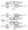
- Ear, Head, and Torso Geometry e.g. characterized by Head Related Transfer Functions (HRTF), combined with knowledge of spectral profile and location of current sound sources, provide the means for deciding upon which frequency bands that, at a given time, contribute most to the BEE seen by the listener or the Hearing Instrument. This corresponds to the system outlined in FIG. 1 .
- HRTF Head Related Transfer Functions
- FIG. 1 shows a block diagram of an embodiment of a listening device comprising a BEE maximizer algorithm, implemented without exchanging information between listening devices located at left and right ears of a user, respectively (bilateral system).
- the listening device comprises a forward path from an input transducer ( Microphones ) to an output transducer ( Receivers ), the forward path comprising a processing unit (here blocks (from left to right) Localization, Source Extraction, Source enhancement, Additional HI processing, and Transposition engine, BEE Provider and Additional HI processing ) for processing (e.g.
- the enhancement of the signal of the forward path comprises a dynamic application of a BEE algorithm as described in the present application.
- the listening device comprises an analysis path for analysing a signal of the forward path and influencing the processing of the signal path, including providing the basis for the dynamic utilization of the BEE effect.
- the analysis path comprises blocks BEE Locator and BEE Allocator.
- the block BEE Locator is adapted to provide an estimate of donor range(s), i.e. the spectral location of BEE's, associated with the present sound sources, in particular to provide a set of potential donor frequency bands DONOR s (n) for a given sound source s, for which the BEE associated with source s is useful.
- the BEE Locator uses inputs concerning the head and torso geometry of a user of the listening device (related to the propagation of sound to the user's left and right ears) stored in a memory of the listening device (cf. signal HTG from medium Head and torso geometry ), e.g. in the form of Head Related Transfer Functions stored in a memory of the listening device.
- the estimation ends up with a (sorted) list of bands that contribute to the better ear effect seen by the listening device(s) in question, cf. signal PDB which is used as an input to the BEE Allocator block.
- the block BEE Allocator provides a dynamic allocation of the donor bands with most spatial information (as seen by the listening device in question) to the target bands with best spatial reception (as seen by the wearer (user) of the listening device(s)), cf. signal DB-BEE which is fed to the Transposition engine, BEE Provider block.
- the BEE Allocator block identifies the frequency bands - termed target frequency bands - where the user has an acceptable hearing ability AND that contribute poorly to the wearer's current spatial perception and speech intelligibility such that their information may advantageously be substituted with the information with good BEE (from appropriate donor bands).
- the allocation of the identified target bands is performed in the BEE Allocator block based on the input DB-BEE input from the BEE Locator block and the input HLI concerning a user's (frequency dependent) hearing ability stored in a memory of the listening device (here medium Hearing Loss ).
- the information about a user's hearing ability comprises e.g.
- the blocks BEE Locator, BEE Allocator and Transposition engine, BEE Provider and Additional HI processing together form part of or constitute the BEE Maximizer algorithm.
- Other functional units may additionally be present (fully or partially located) in an analysis path of a listening device according to the present disclosure, e.g. feedback estimation and/or cancellation, noise reduction, compression, etc.
- the Transposition engine, BEE Provider block receives as inputs the input signal SL of the forward path and the DB-BEE signal from the BEE Allocator block and provides as an output signal TB-BEE comprising target bands with adaptively allocated BEE-information from appropriate donor bands.
- the enhanced signal TB-BEE is fed to the Additional HI processing block for possible further processing of the signal (e.g. compression, noise reduction, feedback reduction, etc.) before being presented to a user via an output transducer (here block Receivers ).
- processing of a signal of the forward path may be performed in the Localization, Source Extraction, Source enhancement, Additional HI processing block prior to the BEE maximizer algorithm being applied to the signal of the forward path.
- the impact of the Ear, Head, and Torso Geometry on the BEE is estimated without the knowledge of the individual HRTFs by comparing the estimated source signals across the ears of a user.
- the system of FIG. 2 comprises e.g. left and right listening devices as shown and described in connection to FIG. 1 .
- the left and right listening devices ( LD-1 (top device), LD-2 (bottom device)) of the system of FIG. 2 comprise transceivers for establishing a wireless communication link ( WL ) between them.
- information about donor frequency bands DONOR s (n) for a given sound source s, for which the BEE associated with source s is useful can be exchanged between the left and right listening devices (e.g. between respective BEE Locator blocks, as shown in FIG. 2 ).
- information allowing a direct comparison of BEE and SNR values in the left and right listening devices for use in the dynamic allocation of available donor bands to appropriate target bands can be exchanged between the left and right listening devices (e.g. between respective BEE Allocator blocks, as shown in FIG.
- information allowing a direct comparison of other information e.g. related to sound source localization, e.g. related to or including microphone signals or signals from sensors located locally in or at the left or right listening devices, respectively, e.g. sensors related to the local acoustic environment, e.g. howl, modulation, noise, etc. can be exchanged between the left and right listening devices (e.g. between the respective Localization, Source Extraction, Source enhancement, Additional HI processing blocks, as shown in FIG. 2 ).
- the WL -indications are only intended to indicate the exchange of data, the physical exchange may or may not be performed via the same link.
- the information related to the head and torso geometry of a user of the listening devices is omitted in the left and/or right listening devices.
- information is indeed stored in one or both instruments, or made available from a database accessible to the listening devices, e.g. via a wireless link (cf. medium Head and torso geometry in FIG. 2 ).
- FIG. 1 Further embodiments and modifications of a listening device and a bilateral listening system based on left and right listening devices as illustrated in FIG. 1 are further discussed in the following. Likewise, further embodiments and modifications of a binaural listening system as illustrated in FIG. 2 are further discussed in the following.
- FIG. 3 The better ear effect as discussed in the present application is illustrated in FIG. 3 by some simple examples of sound source configurations.
- the four examples provide simplified visualizations of the calculations that lead to the estimation of which frequency regions that provide a BEE for a given source.
- the visualizations are based on three sets of HRTF's chosen from Gardner and Martin's KEMAR HRTF database [Gardner and Martin, 1994].
- the source spectra are flat (impulse sources), and the visualizations therefore neglect the impact of the source magnitude spectra, which would additionally occur in practice.
- Example 1 FIG. 3a Example 2, FIG. 3b Example 3, FIG. 3c Example 4, FIG. 3d Target source 20° to the left 50° to the right Front Front Noise source(s) Front 20° to the left 50° to the right 20° to the left 50° to the right 20° to the left 50° to the right.
- FIG. 3a, 3b , 3c, 3d Each example (1, 2, 3, 4) is contained in a single figure ( FIG. 3a, 3b , 3c, 3d , respectively), the sources present and their location relative to each other is summarized in the above table.
- the upper middle panel of each of FIG. 3a-3d shows the spatial configuration of the source and noise(s) signals corresponding to the table above.
- the two outer (left and right) upper panels of each of FIG. 3a-3d show the Power Spectral Density (PSD) of the source signal and the noise signal(s) when they reach each ear (left ear PSD to the left, right ear PSD to the right).
- the outer (left and right) lower panels of each of FIG. 3a-3d (immediately below the respective PSD's) show the SNR for the respective ears.
- the middle lower panel of each of FIG. 3a-3d indicates the location (left/right) of the better ear effect (BEE, i.e. the ear having the better SNR) as a function of frequency (e.g. if SNR(right) > SNR(left) at a given frequency, the BEE is indicated in the right part of the middle lower panel, and vice versa).
- BEE better ear effect
- the size of the BEE difference in dB between the SNR curves of the left and right ears, respectively
- two sound sources are assumed to be present in the vicinity of the user, one comprising noise, the other a target sound.
- FIG. 3a, 3b and 3c two sound sources are assumed to be present in the vicinity of the user, one comprising noise, the other a target sound.
- the BBE is predominantly on the left ear.
- the BBE is predominantly on the left ear at the relatively lower frequencies (below 5 kHz) and predominantly on the right ear at the relatively higher frequencies (above 5 kHz), with deviations there from in narrow frequency ranges around 4.5 kHz and 8 kHz, respectively.
- the examples use impulse sources, so basically the examples are just comparisons of the magnitude spectra of the measured HRTF's (and do not include the effect of spectral coloring, when an ordinary sound source is used, but the simplified examples nevertheless illustrate principles of the BEE utilized in embodiments of the present invention).
- the Power Spectral Density in comparison to the Short Time Fourier Transforms (STFT's) is used to smooth the magnitude spectra for ease of reading and understanding.
- STFT's Short Time Fourier Transforms
- the two noise sources are attenuated 12 dB.
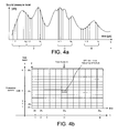
- FIG. 4a illustrates a time dependent sound signal (amplitude versus time), its sampling in an analogue to digital converter and a grouping of time samples in frames, each comprising N s samples.
- FIG. 4b illustrates a resulting 'map' of time-frequency units after a Fourier transformation (e.g. a DFT) of the input signal of FIG. 4a , where a given time-frequency unit m, k corresponds to one DFT-bin and comprises a complex value of the signal (magnitude and phase) in a given time frame m and frequency band k.
- a Fourier transformation e.g. a DFT
- a given frequency band is assumed to contain one (generally complex) value of the signal in each time frame. It may alternatively comprise more than one value.
- the terms 'frequency range' and 'frequency band' are used interchangeably in the present disclosure.
- a frequency range may comprise one or more frequency bands.
- the Short Time Fourier Transform (STFT) is approximated with the periodic Discrete Fourier Transform (DFT).
- DFT Discrete Fourier Transform
- the STFT obtained with a window function w[m] that balances the trade-off between time-resolution and frequency-resolution via its shape and length.
- the size of the DFT K specifies the sampling of the frequency axis, with the rate of FS / K , where FS is the system sample rate:
- the STFT is sampled in time and frequency, and each combination of n and k specifies a single time-frequency unit.
- the range of k 's corresponds to a spectrum.
- the range of n 's corresponds to a time-domain signal restricted to the frequency range of the k 'th channel.
- the BEE is provided via a frequency transposition engine that is capable of individually combining magnitude and phase of one or more donor bands with magnitude and phase, respectively, of a target band to provide a resulting magnitude and phase, respectively, of the target band.
- D-FB1, D-FB2, ...., D-FBq in FIG. 5 D-FB1, D-FB2, ...., D-FBq in FIG. 5
- kt is an index for the available target frequency bands (cf. T-FB1, T-FB2, ...., T-FBp in FIG. 5 )
- the SUM is made over the available kd's and where ⁇ and ⁇ are constants (e.g. between 0 and 1).
- the frequency transposition is e.g. adapted to provide that transposing the donor frequency range to the target frequency range:
- other transposition designs may be
- FIG. 5 illustrates an example of the effect of the transposition process (the (Transposition engine in FIG. 1, 2 ).
- the vertical axes have low frequencies in the bottom and high frequencies at the top, corresponding to frequency bands FB1, FB2, ..., FBi, ..., FBK, increasing index i corresponding to increasing frequency.
- the left instrument transpose three donor bands (D-FBi) from the donor range (comprising donor frequency bands D-FB1, D-FB2, ..., D-FBq) to the target range (comprising target frequency bands T-FB1, T-FB2, ..., T-FBp), and show that it is not necessary to maintain the natural frequency ordering of the bands.
- the right instrument shows a configuration where the highest target band receives both magnitude and phase from the same donor band.
- the next lower target band receives magnitude from one donor frequency band the phase from another (lower lying) donor frequency band.
- the lowest frequency band only substitutes its magnitude with the magnitude from the donor band, while the phase of the target band is kept.
- FIG. 5 provides a few simple examples of configurations of the transposition engine. Other transposition strategies may be implemented by the transposition engine. As the BEE occurs mainly at relatively higher frequencies, and is mainly needed at relatively lower frequencies, the examples throughout the document have the donor frequency range above the target frequency range. This is, however, not a necessary constraint.
- the noise term may function as a container for all signal parts that cannot be attributed to an identified source.
- the described calculations are required for all identified sources, although there will be a great degree of overlap and shared calculations.
- Microphone array techniques provide an example of full source signal estimation in source separation. Essentially the microphone array techniques separate the input into full bandwidth signals that originate from various directions. Thus if the signal originating from a direction is dominated by a single source, this technique provides a representation of that source signal.
- Another application of the binary masks is with directional microphones (possibly achieved with the microphone array techniques or beamforming mentioned above. If one microphone is more sensitive to one direction than to another, then the time-frequency units where the first microphone are louder than the second, indicates that the sound arrives from the direction where the first microphone is more sensitive.
- the present invention does not necessarily require a full separation of the signal, in the sense that a perfect reconstruction of a source's contribution to the signal that a given microphone or artificial microphone, sometimes used in beamforming and microphone array techniques, receives.
- the partial source signal estimation may take place as a booking that merely assign time-frequency units to the identified sources or the noise.
- the global signal-to-noise ratio 10 ⁇ log ⁇ ⁇ n ⁇ x n 2 ⁇ n ⁇ v n 2 ,
- this value does not reflect the spectral and temporal changes of the signals, instead the SNR in a specific time interval and frequency interval is required.
- a SNR measure based on the Short Time Fourier Transform of x[n] x[n] and v ( n ), denoted X[n,k] and N[n,k], respectively, fulfils the requirement SNR n k 10 ⁇ log ⁇ X ⁇ n k 2 N ⁇ n k 2 . With this equation the SNR measure is confined to a specific time instant n and frequency k and thus local.
- HRTF Head related transfer functions
- the head related transfer function (HRTF) is the Fourier Transform of the head related impulse response (HRIR). Both characterize the transformation that a sound undergoes when travelling from its origin to the tympanic membrane.
- the hearing instrument Given the separated source signals in the time-frequency domain (after the application of the STFT), i.e. X s l n k and X s r n k (although a binary mask associated with the source, or an estimate of the magnitude spectrum of that signal will be sufficient), and an estimate of the angle of incidence in the horizontal plane, the hearing instrument compares the local SNR's across the ears to estimate the frequency bands for which this source have beneficial SNR differences. The estimation takes place for one or more, such as a majority or all present identified sound sources.
- the BEE is the difference between the source specific SNR at the two ears
- BEE s l n k SNR s l n k - SNR s r n k ⁇ ⁇ SNR s l n k > ⁇
- BEE s r n k SNR s r n k - SNR s l n k ⁇ ⁇ SNR s r n k > ⁇ SNR
- s is the currently selected source
- the present invention describes two different approaches to estimating the BEE.
- One method do not require the hearing aids (assuming one for each ear) to exchange information about the sources.
- the approach also works for a monaural fit.
- the other approach utilizes communication in a binaural fit to exchange the relevant information.
- the hearing instrument Given that the hearing instrument can separate the sources - at least assign a binary mask, and estimate the angle of incidence in the horizontal plane, the hearing instrument utilizes the stored individual HRTF database to estimate the frequency bands where this source should have beneficial BEE. The estimation takes place for one or more, such as a majority or all present identified sound sources.
- the selection in time frame n for a given source s is as follows: select bands (indexed by k ) that fulfill SNR s n k > ⁇ SNR ⁇ ILD k ⁇ s ⁇ s > ⁇ ILD
- select bands (indexed by k ) that fulfill SNR s n k > ⁇ SNR ⁇ ILD k ⁇ s ⁇ s > ⁇ ILD
- T SNR and T ILD are threshold values for the signal to noise ratios and interaural level differences, respectively.
- the threshold values T SNR and T ILD are constant over frequency. They may, however, be frequency dependent.
- the hearing instrument wearer's individual left and right HRTFs are preferably mapped (in advance of normal operation of the hearing instrument) and stored in a database of the hearing instrument (or at least in a memory accessible to the hearing instrument).
- specific clinical measures to establish the individual or group values of T SNR and T ILD are performed and the results stored in the hearing instrument in advance of its normal operation.
- the approach may be used for bilateral fits (i.e. two hearing aids without inter-instrument communication) and monaural fits (one hearing aid).
- the instrument is capable of estimating the magnitude of each source at the other instrument. From that estimate it is possible for a set of bilaterally operating hearing instruments to approximate the binaural BEE estimation described in the next section without communication between them.
- the selection in the left instrument in time frame n for source s is as follows: Select the set of bands (indexed by k ) DONOR s l n that fulfills BEE s l n k > ⁇ BEE .
- ⁇ BEE ⁇ BEE is a threshold parameter.
- the threshold value ⁇ BEE is constant over frequency and location of the listening device (left, right). They may, however, be different from left to right and/or frequency dependent.
- specific clinical measures in order to establish individual or group-specific values are performed in advance of normal operation of the hearing instrument(s).
- the BEE Provider is placed after the BEE Allocator on the flowcharts (cf. FIG. 1 and 2 ), the invention is more easily described by going through the BEE Provider first.
- the transposition moves the donor frequency range to the target frequency range.
- FIG. 6 illustrates two examples of the effect of the transposition process, FIG. 6a a so-called asynchronous transposition and FIG. 6b a so-called synchronous transposition.
- FIG. 7 illustrates a so-called enhanced mono mode and FIG. 8 illustrates an ILD-transposition mode.
- FIG. 6a, 6b , 7, 8 illustrates one or more donor ranges and a target range for a left and a right hearing instrument, each graph for a left or right instrument having a donor frequency axis and a target frequency axis, the arrow on the frequency axes indicating a direction of increasing frequency.
- the hearing instrument configures the transposition independently, such that the same frequency band may be used as target for one source in one instrument, and another source in the other instrument, and consequently the two sources will be perceived as more prominent in one ear each.
- FIG. 6a shows an example of asynchronous transposition.
- the left instrument transposes the frequency range where source 1 (corresponding to Donor 1 range in FIG. 6a ) has beneficial BEE to the target range while the right instrument transposes the frequency range where source 2 ( Donor 2 range ) has beneficial BEE to the same target range.
- the hearing instruments share donor and target configuration, such that the frequency in the instrument with the beneficial BEE and the signal in the other instrument is transposed to the same frequency range.
- frequency range in both ears are there is used for that source.
- the synchronized transposition may use the same frequency range for multiple sources.
- the synchronization may be achieved by communication between the hearing instruments, or via the bilateral approximation to binaural BEE estimation, where the hearing instrument can estimate what the other hearing instrument will do without the need for communication between them.
- the hearing instrument with the beneficial BEE shares that signal with the instrument with the poor BEE.
- the physical BEE may be reduced by choice, however, both ears will receive the signal that was estimated from the most positive source specific SNR.
- the right instrument receives the transposed signal from the left instrument and (optionally) scales this according to the desired ILD.
- an ILD of a (relatively higher frequency) donor frequency band is determined (symbolized by dashed arrows ILD in FIG. 8 ) and applied to a (relatively lower frequency) target frequency band (symbolized by arrows A in FIG. 8 ).
- the ILD is e.g. determined in one of the instruments as the ratio of the magnitude of the signals from the respective hearing instruments in the frequency band in question (thus only a transfer of the magnitude of the signal in the frequency range in question from one instrument to the other is needed).
- the ILD may be e.g. applied in both instruments (only shown in FIG. 8 to be applied to the target range of the left hearing instrument).
- the next step aims at finding the frequency bands that contribute poorly to the wearer's current spatial perception and speech intelligibility such that their information may be substituted with the information with good BEE.
- Those bands are referred to as the target frequency bands in the following.
- the next steps involve the allocation of the identified target ranges. How this takes place is described after the description of the estimation of the target range.
- a potential target band may e.g. be determined as a frequency band where a user's hearing ability is above a predefined level (e.g. based on an audiogram for the user).
- a potential target band may, however, alternatively or additionally, be determined as a frequency band for which a user has the ability to correctly decide on which ear the level is the larger, when sounds of different levels are played simultaneously to the user's left and right ears.
- a corresponding test that may influence the choice of potential frequency bands for a user could be a test wherein the user's ability to correctly sense a difference in phase, when sounds (in a given frequency band) of different phase are played simultaneously to the user's left and right ears, is tested.
- the hearing instrument(s) do not have direct access to the BEE estimate, although it may be estimated from the combination of the separated sources and the knowledge of the individual HRTF's.
- target bands fulfill BEE s n k ⁇ ⁇ BEE ⁇ SNR s n k ⁇ ⁇ SNR for all sources s using the indirect comparison.
- the selection of target bands can also happen through the monaural SNR measure, by selecting the frequency bands that don't have beneficial SNR or ILD for all sources s SNR s n k ⁇ ⁇ SNR ⁇ ILD k ⁇ s ⁇ s ⁇ ILD
- the target frequency bands are the frequency bands that don't have beneficial BEE (via the indirect comparison) in either instrument and don't have beneficial SNR in either instrument for any source S BEE s n k ⁇ ⁇ BEE ⁇ SNR s l n k ⁇ ⁇ SNR ⁇ SNR s r n k ⁇ ⁇ SNR
- the binaural estimation of target frequency bands involve the direct comparison of left and right instruments BEE and SNR values.
- the (target) frequency bands whose SNR difference do not exceed the BEE threshold may be substituted with the contents of the (donor) frequency bands where a beneficial BEE occurs.
- the two hearing instruments are not operating in synchronous mode the two instruments do not coordinate their targets and donors, thus a frequency band with a large negative BEE estimate (that means that there is a beneficial BEE in the other instrument) can be substituted as well.
- the aim can be formulated as maximizing the overall spatial contrast between a single source (a speaker) and one or more other sources (being other speakers and noise sources).
- An example of this focusing strategy is illustrated in FIG. 9 , where two sources occupying Donor 1 range and Donor 2 range, respectively, are available, but only two donor bands from the Donor 1 range are transposed to two target bands in the Target range.
- a single source can be applied, e.g. the signal that contains speech having the highest energy content, e.g. when averaged over a predefined time period, e.g. ⁇ 5 s.
- a source coming approximately from the front of the user may be selected.
- a source may selected by a user via a user interface, e.g. a remote control.
- the strategy can also be called "focus BEE", due to the fact that it provides as much BEE for a single object as possible, enabling the wearer to focus solely on that sound.
- the hearing instrument may try to divide the available frequency bands between a number of sources.
- the aim can be formulated as maximizing the number of independently received spatial contrasts, i.e., provide "clear" spatial information for as many of the current sound sources as the individual wearer can cope.
- the second mode is called “scanning BEE", due to the fact that it provides BEE for as many objects as possible, depending on the wearer, enabling the wearer to scan/track multiple sources.
- This operation mode is likely to require better residual spatial skills than for the single source BEE enhancement.
- the scanning BEE mode is illustrated in FIG. 10 , where two sources occupying Donor 1 range and Donor 2 range, respectively, are available, and one donor band (Donor FB) from each of the Donor 1 range and Donor 2 range are transposed to two different target bands (Target FB) in the Target range.
- FIG. 11 schematically illustrates embodiments of a listening device for implementing methods and ideas of the present disclosure.
- FIG. 11a shows an embodiment of a listening device ( LD ), e.g. a hearing instrument, comprising a forward path from an input transducer ( MS ) to an output transducer ( SP ), the forward path comprising a processing unit ( SPU ) for processing (e.g. applying a frequency dependent gain to) an input signal MIN picked up by the input transducer (here microphone system MS ), or a signal derived therefrom, and providing an enhanced signal REF to the output transducer (here speaker SP ).
- the forward path from the input transducer to the output transducer (here comprising SUM-unit '+' and signal processing unit SPU ) is indicated with a bold line.
- the listening device (optionally) comprises a feedback cancellation system (for reducing or cancelling acoustic feedback from an 'external' feedback path from the output transducer to the input transducer of the listening device) comprising a feedback estimation unit (FBE) for estimating the feedback path and SUM unit ('+') for subtracting the feedback estimate FBest from the input signal MIN, thereby ideally cancelling the part of the input signal that is caused by feedback.
- the resulting feedback corrected input signal ER is further processed by the signal processing unit ( SPU ).
- the processed output signal from the signal processing unit termed the reference signal REF, is fed to the output transducer ( SP ) for presentation to a user.
- An analysis unit (ANA) receives signals from the forward path (here input signal MIN, feedback corrected input signal ER , reference signal REF, and wirelessly received input signal WIN).
- the analysis unit ( ANA ) provides a control signal CNT to the signal processing unit ( SPU ) for controlling or influencing the processing in the forward path.
- the algorithms for processing an audio signal are executed fully or partially in the signal processing unit ( SPU ) and the analysis unit ( ANA ).
- the input transducer ( MS ) is representative of a microphone system comprising a number of microphones, the microphone system allowing to modify the characteristic of the system in one or more spatial directions (e.g. to focus the sensitivity in a forward direction of a user (attenuate signals from a rear direction of the user)).
- the input transducer may comprise a directional algorithm allowing the separation of one or more sound sources from the sound field. Such directional algorithm may alternatively be implemented in the signal processing unit.
- the input transducer may further comprise an analogue to digital conversion unit for sampling an analogue input signal and provide a digitized input signal.
- the input transducer may further comprise a time to time-frequency conversion unit, e.g. an analysis filter bank, for providing the input signal in a number of frequency bands allowing a separate processing of the signal in different frequency bands.
- the output transducer may comprise a digital to analogue conversion unit and/or a time-frequency to time conversion unit, e.g.
- the listening device can be adapted to be able to process information relating to the better ear effect, either derived solely from local information of the listening device itself (cf. FIG. 1 ) or derived partially from data received from another device via the wireless interface (antenna, transceiver Rx-Tx and signal WIN ), whereby a binaural listening system comprising two listening devices located at left and right ears of a use can be implemented (cf. FIG. 2 ).
- Other information than information related to the BEE may be exchanged via the wireless interface, e.g. commands and status signals and/or audio signals (in full or in part, e.g. one or more frequency bands of an audio signal).
- Information related the BEE may e.g. be signal to noise ( SNR) measures, interaural level differences ( ILD ), donor frequency bands, etc.
- FIG. 11b shows another embodiment of a listening device ( LD ) for implementing methods and ideas of the present disclosure.
- the embodiment of a listening device ( LD ) of FIG. 11b is similar to the one illustrated in FIG. 11 a.
- the input transducer comprises a microphone system comprising two microphones ( M1 , M2 ) providing input microphone signals IN1, IN2 and a directional algorithm ( DIR ) providing a weighted combination of the two input microphone signals in the form of directional signal IN , which is fed to processing block ( PRO ) for further processing, e.g. applying a frequency dependent gain to the input signal and providing a processed output signal OUT , which is fed to the speaker unit ( SPK ).
- DIR directional algorithm
- Units DIR and PRO correspond to signal processing unit ( SPU ) of the embodiment of FIG. 11a .
- the embodiment of a listening device ( LD ) of FIG. 11b comprises two feedback estimation paths, one for each of the feedback paths from speaker SPK to microphones M1 and M2, respectively.
- a feedback estimate ( FB est1 , FB est2 ) for each feedback path is subtracted from the respective input signals IN1, IN2 from microphones ( M1, M2 ) in respective subtraction units ('+').
- the outputs of the subtraction units ER1, ER2 representing respective feedback corrected input signals are fed to the signal processing unit ( SPU ), here to the directional unit ( DIR ) .
- Each feedback estimation path comprises a feedback estimation unit ( FBE1, FBE2 ) , e.g. comprising an adaptive filter for filtering an input signal ( OUT ( REF )) and providing a filtered output signal ( FB est1 , FB est2 , respectively) providing an estimate of the respective feedback paths.
- FBE1, FBE2 a feedback estimation unit
- FB est1 , FB est2 a filtered output signal
- the listening device of FIG. 11b can be can be adapted to be able to process information relating to the better ear effect, either derived solely from local information of the listening device itself (cf. FIG.
- a binaural listening system comprising two listening devices located at left and right ears of a use can be implemented (cf. FIG. 2 ).
- the analysis unit ( ANA ) and the signal processing unit ( SPU ) comprises the necessary BEE Maximizer blocks ( BEE Locator, and BEE Allocator, and Transpostion engine, BEE Provider, storage media holding relevant data, etc.).
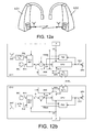
- FIG. 12a shows an example of a binaural or a bilateral listening system comprising first and second listening devices LD1, LD2, each being e.g. a listening device as illustrated in FIG. 11a or in FIG. 11 b.
- the listening devices are adapted to exchange information via transceivers RxTx.
- the information that can be exchanged between the two listening devices comprises e.g. information, control signals and/or audio signals (e.g. one or more frequency bands of an audio signal, including BEE information).
- FIG. 12b shows an embodiment of a binaural or a bilateral listening system, e.g. a hearing aid system, comprising first and second listening devices ( LD-1, LD-2), here termed hearing instruments.
- the first and second hearing instruments are adapted for being located at or in left and right ears of a user.
- the hearing instruments are adapted for exchanging information between them via a wireless communication link, e.g. a specific inter-aural (IA) wireless link (IA-WL).
- the two hearing instruments (LD-1, LD-2 ) are adapted to allow the exchange of status signals, e.g. including the transmission of characteristics of the input signal (including BEE information) received by a device at a particular ear to the device at the other ear.
- each hearing instrument comprises antenna and transceiver circuitry (here indicated by block IA-RxlTx ).
- Each hearing instrument LD-1 and LD-2 comprise a forward signal path comprising a microphone ( MIC ) a signal processing unit ( SPU ) and a speaker ( SPK ).
- the hearing instruments further comprises a feedback cancellation system comprising a feedback estimation unit ( FBE ) and combination unit ('+') as described in connection with FIG. 11 .
- a signal WIN comprising BEE-information (and possibly other information) generated by Analysis unit (ANA ) of one of the hearing instruments (e.g. LD-1 ) is transmitted to the other hearing instrument (e.g.
- the information and control signals from the local and the opposite device are e.g. in some cases used together to influence a decision or a parameter setting in the local device.
- the control signals may e.g. comprise information that enhances system quality to a user, e.g. improve signal processing, information relating to a classification of the current acoustic environment of the user wearing the hearing instruments, synchronization, etc.
- the BEE information signals may comprise directional information (e.g. ILD) and/or one or more frequency bands of the audio signal of a hearing instrument for use in the opposite hearing instrument of the system.
- Each (or one of the) hearing instruments comprises a manually operable user interface (UI ) for generating a control signal UC, e.g. for providing a user input to the analysis unit (e.g. for selecting a target signal among a number of signals in the sound field picked up by the microphone system ( MIC )) .
- UI manually operable user interface
- UC control signal
- the hearing instruments each further comprise wireless transceivers ( ANT, A-Rx / Tx ) for receiving a wireless signal (e.g. comprising an audio signal and/or control signals) from an auxiliary device, e.g. an audio gateway device and/or a remote control device.
- the hearing instruments each comprise a selector/mixer unit (SEL / MIX) for selecting either of the input audio signal INm from the microphone or the input signal INw from the wireless receiver unit ( ANT, A-Rx / Tx) or a mixture thereof, providing as an output a resulting input signal IN .
- the selector/mixer unit can be controlled by the user via the user interface ( UI ), cf.
- control signal UC and/or via the wirelessly received input signal (such input signal e.g. comprising a corresponding control signal (e.g. from a remote control device) or a mixture of audio and control signals (e.g. from a combined remote control and audio gateway device)).
- input signal e.g. comprising a corresponding control signal (e.g. from a remote control device) or a mixture of audio and control signals (e.g. from a combined remote control and audio gateway device)).
Landscapes
- Health & Medical Sciences (AREA)
- General Health & Medical Sciences (AREA)
- Neurosurgery (AREA)
- Otolaryngology (AREA)
- Physics & Mathematics (AREA)
- Engineering & Computer Science (AREA)
- Acoustics & Sound (AREA)
- Signal Processing (AREA)
- Stereophonic System (AREA)
- Headphones And Earphones (AREA)
Claims (15)
- Ein Verfahren zum Verarbeiten von Audiosignalen, die von einem Schallfeld mit Hilfe eines Mikrophonsystems eines binauralen Hörsystems aufgenommen werden, das linke und rechte Hörvorrichtungen aufweist, die ausgebildet sind an einem linken bzw. rechten Ohr eines Nutzers getragen zu werden, wobei das Schallfeld Schallsignale von einer oder mehreren Schallquellen aufweist, wobei die Schallsignale auf den Nutzer aus einer oder mehreren Richtungen bezüglich des Nutzers eintreffen und wobei die linken und rechten Hörvorrichtungen Transceiver zum Herstellen einer Kommunikationsverbindung zwischen ihnen aufweisen, wobei das Verfahren umfasst:b1) Bereitstellen von Informationen über eine Hörfähigkeit des Nutzers, die von der Frequenz eines Schallsignals abhängt;b2) Bestimmen einer Anzahl von Zielfrequenzbändern, für die die Hörfähigkeit des Nutzers ein vordefiniertes Hörfähigkeitskriterium erfüllt; und Durchführen von Schritten c1) bis c3) für jede der an dem linken bzw. rechten Ohr des Nutzers angeordneten linken und rechten Hörvorrichtungen:c1) Vorsehen einer dynamischen Trennung von Schallsignalen der einen oder mehreren Schallquellen abhängig von Zeit, Frequenz und Herkunftsrichtung der Schallsignale bezüglich des Nutzers;c2) Auswählen eines Signals aus den dynamisch getrennten Schallsignalen;c3) Bestimmen einer Signal-Rausch-Verhältnis-Messgröße (SNR-Messgröße), die eine Stärke des ausgewählten Signals relativ zu anderen Signalen des Schallfeldes für das ausgewählte Signal und Hörvorrichtung abhängig von Zeit, Frequenz und Herkunftsrichtung des ausgewählten Signals bezüglich des Nutzers und dem Ort und der wechselseitigen Stärke der Schallquellen angibt;
Durchführen von Schritten c4bin) bis d) in wenigstens einem der linken und rechten Hörvorrichtungen:c4bin)Bestimmen einer Besseres-Ohr-Effekt Messgröße für die linke Hörvorrichtung als Differenz zwischen den Werten der SNR-Messgröße für das ausgewählte Signal für die linke bzw. rechte Hörvorrichtung oder Bestimmen einer Besseres-Ohr-Effekt Messgröße für die rechte Hörvorrichtung als Differenz zwischen den Werten der SNR-Messgröße für das ausgewählte Signal für die rechte bzw. linke Hörvorrichtung;c5bin)Bestimmen in den linken und/oder rechten Hörvorrichtungen einer Anzahl von Geberfrequenzbändern des ausgewählten Signals zu einer bestimmten Zeit, zu der die Besseres-Ohr-Effekt Messgröße für das ausgewählte Signal über einem vorbestimmten Grenzwert ist;d) Transponieren eines Geberfrequenzbandes des ausgewählten Signals in der linken und/oder rechten Hörvorrichtung - zu einer bestimmten Zeit - in ein Zielfrequenzband, wenn ein vorbestimmtes Transpositionskriterium erfüllt ist. - Verfahren gemäß Anspruch 1, wobei das vorbestimmte Transpositionskriterium umfasst, dass das wenigstens eine Geberfrequenzband des ausgewählten Signals mit einem potentiellen Geberfrequenzband des ausgewählten Signals überlappt oder identisch zu diesem ist.
- Verfahren gemäß Anspruch 1 oder 2, wobei Schritte c2) bis c5bin) für zwei oder mehr, beispielsweise für alle, der dynamisch getrennten Schallsignale durchgeführt werden und wobei alle anderen detektierten Signalquellen als das ausgewählte Signal als Rauschen betrachtet werden, wenn die SNR-Messgröße bestimmt wird.
- Verfahren gemäß irgendeinem der Ansprüche 1 bis 3, wobei in Schritt c2) ein Zielsignal aus den dynamisch getrennten Schallsignalen ausgewählt wird und wobei Schritt d) für das Zielsignal durchgeführt wird und wobei alle anderen detektierten Signalquellen als das Zielsignal als Rauschen betrachtet werden.
- Verfahren gemäß Anspruch 4, wobei das Zielsignal aus den getrennten Signalquellen als die Quelle ausgewählt wird, welche ein oder mehrere der Kriterien erfüllt, die umfassen: a) Besitzen des größten Energieinhalts, b) Am nächsten zum Nutzer Positioniert sein, c) Positioniert sein vor dem Nutzer, d) Aufweisen der lautesten Sprachsignalkomponenten.
- Verfahren gemäß Anspruch 4 oder 5, wobei das Zielsignal von dem Nutzer auswählbar ist, beispielsweise mit Hilfe einer Benutzerschnittstelle, die eine Auswahl zwischen den augenblicklich getrennten Schallquellen oder eine Auswahl von Schallquellen aus einer bestimmten Richtung bezüglich des Nutzers, etc. ermöglicht.
- Verfahren gemäß irgendeinem der Ansprüche 1 bis 6, wobei Signalkomponenten die nicht zu einem der dynamisch getrennten Schallsignale zugeordnet sind als Rauschen betrachtet werden.
- Verfahren gemäß irgendeinem der Ansprüche 1 bis 7, wobei Schritt d) umfasst Ersetzen der Größe und/oder Phase des Zielfrequenzbandes durch die Größe und/oder Phase eines Geberfrequenzbandes.
- Verfahren gemäß irgendeinem der Ansprüche 1 bis 8, wobei Geberfrequenzbänder oberhalb einer vorbestimmten minimalen Geberfrequenz ausgewählt werden und wobei Zielfrequenzbänder unterhalb einer vorbestimmten maximalen Zielfrequenz ausgewählt werden.
- Verfahren gemäß Anspruch 9, wobei die minimale Geberfrequenz und/oder die maximale Zielfrequenz auf die Hörfähigkeit des Nutzers angepasst ist/sind.
- Verfahren gemäß irgendeinem der Ansprüche 1 bis 10, wobei in Schritt b2) ein Zielfrequenzband als ein Band bestimmt wird, für das ein Nutzer die Fähigkeit hat korrekt zu entscheiden auf welchem Ohr der Pegel größer ist, wenn Schall mit verschiedenen Pegeln simultan den linken und rechten Ohren des Nutzers vorgespielt werden.
- Verfahren gemäß irgendeinem der Ansprüche 1 bis 11, wobei Zielfrequenzbänder die schlecht zu der augenblicklichen räumlichen Wahrnehmung des Trägers beitragen und Sprachverständlichkeit bestimmt werden, so dass ihre Information mit der Information eines Geberfrequenzbandes ersetzt werden kann.
- Verfahren gemäß irgendeinem der Ansprüche 1 bis 12, wobei Schritt d) in den linken und rechten Hörvorrichtungen synchron miteinander betrieben wird.
- Ein binaurales Hörsystem umfassend linke und rechte Hörvorrichtungen, die ausgebildet sind, um an linkem bzw. rechtem Ohr eines Nutzers getragen zu werden, wobei jede Hörvorrichtung ein Mikrophonsystem zum Aufnehmen von Schall von einem Schallfeld umfassend Schallsignale von einer oder mehreren Schallquellen aufweist, wobei die Schallsignale auf den Nutzer aus einer oder mehreren Richtungen bezüglich des Nutzers eintreffen, wobei die linken und rechten Hörvorrichtungen Transceiver zum Herstellen einer Kommunikationsverbindung zwischen ihnen aufweisen und wobei das Hörsystem ausgebildet ist von den Mikrophonsystemen der linken und rechten Hörvorrichtungen aufgenommene Audiosignale gemäß dem Verfahren von irgendeinem der Ansprüche 1 bis 13 zu verarbeiten.
- Ein physisches ein Computerprogram speicherndes computerlesbares Medium, umfassend Programmcodemittel, um einem Datenverarbeitungssystem zu ermöglichen die Schritte des Verfahrens von irgendeinem der Ansprüche 1 bis 13 durchzuführen, wenn das Computerprogramm auf dem Datenverarbeitungssystem ausgeführt wird.
Priority Applications (5)
| Application Number | Priority Date | Filing Date | Title |
|---|---|---|---|
| EP20110178463 EP2563045B1 (de) | 2011-08-23 | 2011-08-23 | Verfahren und binaurales System zur Maximierung eines Effekts des besseren Ohrs. |
| DK11178463T DK2563045T3 (da) | 2011-08-23 | 2011-08-23 | Fremgangsmåde og et binauralt lyttesystem for at maksimere en bedre øreeffekt |
| US13/592,100 US9031271B2 (en) | 2011-08-23 | 2012-08-22 | Method and a binaural listening system for maximizing a better ear effect |
| CN201210303754.5A CN102984638B (zh) | 2011-08-23 | 2012-08-23 | 使好耳效应最大化的方法和双耳听音系统 |
| AU2012216394A AU2012216394A1 (en) | 2011-08-23 | 2012-08-23 | A Method and a Binaural Listening System for Maximising a Better Ear Effect |
Applications Claiming Priority (1)
| Application Number | Priority Date | Filing Date | Title |
|---|---|---|---|
| EP20110178463 EP2563045B1 (de) | 2011-08-23 | 2011-08-23 | Verfahren und binaurales System zur Maximierung eines Effekts des besseren Ohrs. |
Publications (2)
| Publication Number | Publication Date |
|---|---|
| EP2563045A1 EP2563045A1 (de) | 2013-02-27 |
| EP2563045B1 true EP2563045B1 (de) | 2014-07-23 |
Family
ID=44582431
Family Applications (1)
| Application Number | Title | Priority Date | Filing Date |
|---|---|---|---|
| EP20110178463 Not-in-force EP2563045B1 (de) | 2011-08-23 | 2011-08-23 | Verfahren und binaurales System zur Maximierung eines Effekts des besseren Ohrs. |
Country Status (5)
| Country | Link |
|---|---|
| US (1) | US9031271B2 (de) |
| EP (1) | EP2563045B1 (de) |
| CN (1) | CN102984638B (de) |
| AU (1) | AU2012216394A1 (de) |
| DK (1) | DK2563045T3 (de) |
Cited By (1)
| Publication number | Priority date | Publication date | Assignee | Title |
|---|---|---|---|---|
| EP3796678A1 (de) * | 2013-11-05 | 2021-03-24 | Oticon A/s | Binaurales hörgerätesystem das dem nutzer erlaubt position einer schallquelle zu ändern |
Families Citing this family (33)
| Publication number | Priority date | Publication date | Assignee | Title |
|---|---|---|---|---|
| US10721574B2 (en) * | 2011-11-04 | 2020-07-21 | Med-El Elektromedizinische Geraete Gmbh | Fitting unilateral electric acoustic stimulation for binaural hearing |
| KR20150020810A (ko) * | 2013-08-19 | 2015-02-27 | 삼성전자주식회사 | 청각 기기 및 양이 청각 모델을 이용한 청각 기기의 피팅 방법 |
| US11412334B2 (en) * | 2013-10-23 | 2022-08-09 | Cochlear Limited | Contralateral sound capture with respect to stimulation energy source |
| CN104681034A (zh) * | 2013-11-27 | 2015-06-03 | 杜比实验室特许公司 | 音频信号处理 |
| DK2897382T3 (da) * | 2014-01-16 | 2020-08-10 | Oticon As | Forbedring af binaural kilde |
| EP2928210A1 (de) | 2014-04-03 | 2015-10-07 | Oticon A/s | Binaurales Hörgerätesystem mit binauraler Rauschunterdrückung |
| GB2527126B (en) * | 2014-06-13 | 2019-02-06 | Elaratek Ltd | Noise cancellation with dynamic range compression |
| US9226090B1 (en) * | 2014-06-23 | 2015-12-29 | Glen A. Norris | Sound localization for an electronic call |
| EP2988531B1 (de) * | 2014-08-20 | 2018-09-19 | Starkey Laboratories, Inc. | Hörhilfesystem mit erkennung der eigenen stimme |
| US10181328B2 (en) | 2014-10-21 | 2019-01-15 | Oticon A/S | Hearing system |
| WO2016096043A1 (en) * | 2014-12-19 | 2016-06-23 | Widex A/S | Method of operating a hearing aid system and a hearing aid system |
| WO2016116160A1 (en) * | 2015-01-22 | 2016-07-28 | Sonova Ag | Hearing assistance system |
| DK3051844T3 (da) * | 2015-01-30 | 2018-01-29 | Oticon As | Binauralt høresystem |
| EP3054706A3 (de) * | 2015-02-09 | 2016-12-07 | Oticon A/s | Binaurales hörsystem und hörgerät mit einer strahlformungseinheit |
| EP3057340B1 (de) * | 2015-02-13 | 2019-05-22 | Oticon A/s | Partnermikrofoneinheit und hörsystem mit einer partnermikrofoneinheit |
| US10575103B2 (en) | 2015-04-10 | 2020-02-25 | Starkey Laboratories, Inc. | Neural network-driven frequency translation |
| CN104853283A (zh) * | 2015-04-24 | 2015-08-19 | 华为技术有限公司 | 一种音频信号处理的方法和装置 |
| WO2016180704A1 (en) | 2015-05-08 | 2016-11-17 | Dolby International Ab | Dialog enhancement complemented with frequency transposition |
| DK3108929T3 (da) * | 2015-06-22 | 2020-08-31 | Oticon Medical As | Lydbehandling til et bilateralt cochleaimplantatsystem |
| DE102015211747B4 (de) * | 2015-06-24 | 2017-05-18 | Sivantos Pte. Ltd. | Verfahren zur Signalverarbeitung in einem binauralen Hörgerät |
| US9843875B2 (en) * | 2015-09-25 | 2017-12-12 | Starkey Laboratories, Inc. | Binaurally coordinated frequency translation in hearing assistance devices |
| CN111988727A (zh) * | 2015-10-08 | 2020-11-24 | 班安欧股份公司 | 扬声器系统中的主动式房间补偿 |
| CN105280195B (zh) | 2015-11-04 | 2018-12-28 | 腾讯科技(深圳)有限公司 | 语音信号的处理方法及装置 |
| EP3185585A1 (de) | 2015-12-22 | 2017-06-28 | GN ReSound A/S | Binaurales hörgerät mit erhaltung der räumlichen signalinformationen |
| US9591427B1 (en) * | 2016-02-20 | 2017-03-07 | Philip Scott Lyren | Capturing audio impulse responses of a person with a smartphone |
| WO2017151482A1 (en) * | 2016-03-01 | 2017-09-08 | Mayo Foundation For Medical Education And Research | Audiology testing techniques |
| DK3214620T3 (da) * | 2016-03-01 | 2019-11-25 | Oticon As | Monaural forstyrrende taleforståelighedsforudsigelsesenhed, et høreapparat og et binauralt høreapparatsystem |
| EP3326685B1 (de) | 2016-11-11 | 2019-08-14 | Oticon Medical A/S | Cochleaimplantatsystem zur verarbeitung der informationen mehrerer klangquellen |
| DE102017201195A1 (de) * | 2017-01-25 | 2018-07-26 | Sivantos Pte. Ltd. | Verfahren zum Betrieb eines binauralen Hörgerätesystems |
| CN107182003B (zh) * | 2017-06-01 | 2019-09-27 | 西南电子技术研究所(中国电子科技集团公司第十研究所) | 机载三维通话虚拟听觉处理方法 |
| EP4418690A3 (de) * | 2019-02-08 | 2024-10-16 | Oticon A/s | Hörgerät mit einem rauschunterdrückungssystem |
| US11043201B2 (en) | 2019-09-13 | 2021-06-22 | Bose Corporation | Synchronization of instability mitigation in audio devices |
| CN111009257B (zh) * | 2019-12-17 | 2022-12-27 | 北京小米智能科技有限公司 | 一种音频信号处理方法、装置、终端及存储介质 |
Family Cites Families (20)
| Publication number | Priority date | Publication date | Assignee | Title |
|---|---|---|---|---|
| US4366349A (en) * | 1980-04-28 | 1982-12-28 | Adelman Roger A | Generalized signal processing hearing aid |
| DK406189A (da) | 1989-08-18 | 1991-02-19 | Otwidan Aps Forenede Danske Ho | Fremgangsmaade og apparat til klassifikation af et blandet tale- og stoejsignal |
| US5144675A (en) | 1990-03-30 | 1992-09-01 | Etymotic Research, Inc. | Variable recovery time circuit for use with wide dynamic range automatic gain control for hearing aid |
| US5473701A (en) | 1993-11-05 | 1995-12-05 | At&T Corp. | Adaptive microphone array |
| EP0820210A3 (de) | 1997-08-20 | 1998-04-01 | Phonak Ag | Verfahren zur elektronischen Strahlformung von akustischen Signalen und akustisches Sensorgerät |
| US7333623B2 (en) | 2002-03-26 | 2008-02-19 | Oticon A/S | Method for dynamic determination of time constants, method for level detection, method for compressing an electric audio signal and hearing aid, wherein the method for compression is used |
| WO2004077090A1 (en) | 2003-02-25 | 2004-09-10 | Oticon A/S | Method for detection of own voice activity in a communication device |
| US20040175010A1 (en) * | 2003-03-06 | 2004-09-09 | Silvia Allegro | Method for frequency transposition in a hearing device and a hearing device |
| US20040175008A1 (en) | 2003-03-07 | 2004-09-09 | Hans-Ueli Roeck | Method for producing control signals, method of controlling signal and a hearing device |
| AU2003904207A0 (en) | 2003-08-11 | 2003-08-21 | Vast Audio Pty Ltd | Enhancement of sound externalization and separation for hearing-impaired listeners: a spatial hearing-aid |
| DK1699261T3 (da) | 2005-03-01 | 2011-08-15 | Oticon As | System og fremgangsmåde til bestemmelse af direktionalitet af lyd detekteret af et høreapparat |
| AU2005201813B2 (en) * | 2005-04-29 | 2011-03-24 | Phonak Ag | Sound processing with frequency transposition |
| EP1742509B1 (de) | 2005-07-08 | 2013-08-14 | Oticon A/S | Vorrichtung und Verfahren zum Eliminieren von Feedback-Rauschen in einem Hörgerät |
| DE102005032274B4 (de) | 2005-07-11 | 2007-05-10 | Siemens Audiologische Technik Gmbh | Hörvorrichtung und entsprechendes Verfahren zur Eigenstimmendetektion |
| AU2008203351B2 (en) * | 2007-08-08 | 2011-01-27 | Oticon A/S | Frequency transposition applications for improving spatial hearing abilities of subjects with high frequency hearing loss |
| EP2026601A1 (de) * | 2007-08-08 | 2009-02-18 | Oticon A/S | Frequenztranspositionsanwendungen zur Verbesserung des räumlichen Hörvermögens von Personen mit hochfrequentem Hörverlust |
| DK2088802T3 (da) | 2008-02-07 | 2013-10-14 | Oticon As | Fremgangsmåde til estimering af lydsignalers vægtningsfunktion i et høreapparat |
| US8705751B2 (en) * | 2008-06-02 | 2014-04-22 | Starkey Laboratories, Inc. | Compression and mixing for hearing assistance devices |
| WO2010115227A1 (en) * | 2009-04-07 | 2010-10-14 | Cochlear Limited | Localisation in a bilateral hearing device system |
| EP2262285B1 (de) * | 2009-06-02 | 2016-11-30 | Oticon A/S | Hörvorrichtung mit verbesserten Lokalisierungshinweisen, deren Verwendung und ein Verfahren |
-
2011
- 2011-08-23 EP EP20110178463 patent/EP2563045B1/de not_active Not-in-force
- 2011-08-23 DK DK11178463T patent/DK2563045T3/da active
-
2012
- 2012-08-22 US US13/592,100 patent/US9031271B2/en not_active Expired - Fee Related
- 2012-08-23 CN CN201210303754.5A patent/CN102984638B/zh not_active Expired - Fee Related
- 2012-08-23 AU AU2012216394A patent/AU2012216394A1/en not_active Abandoned
Cited By (1)
| Publication number | Priority date | Publication date | Assignee | Title |
|---|---|---|---|---|
| EP3796678A1 (de) * | 2013-11-05 | 2021-03-24 | Oticon A/s | Binaurales hörgerätesystem das dem nutzer erlaubt position einer schallquelle zu ändern |
Also Published As
| Publication number | Publication date |
|---|---|
| EP2563045A1 (de) | 2013-02-27 |
| DK2563045T3 (da) | 2014-10-27 |
| CN102984638B (zh) | 2017-08-25 |
| CN102984638A (zh) | 2013-03-20 |
| US20130051566A1 (en) | 2013-02-28 |
| AU2012216394A1 (en) | 2013-03-14 |
| US9031271B2 (en) | 2015-05-12 |
Similar Documents
| Publication | Publication Date | Title |
|---|---|---|
| EP2563045B1 (de) | Verfahren und binaurales System zur Maximierung eines Effekts des besseren Ohrs. | |
| EP2563044B1 (de) | Verfahren, Hörvorrichtung und Hörsystem zur Maximierung eines Effekts des besseren Ohrs. | |
| Kollmeier et al. | Functionality of hearing aids: State-of-the-art and future model-based solutions | |
| Van den Bogaert et al. | Speech enhancement with multichannel Wiener filter techniques in multimicrophone binaural hearing aids | |
| US10567889B2 (en) | Binaural hearing system and method | |
| DK3057335T3 (en) | HEARING SYSTEM, INCLUDING A BINAURAL SPEECH UNDERSTANDING | |
| US20100002886A1 (en) | Hearing system and method implementing binaural noise reduction preserving interaural transfer functions | |
| US9325285B2 (en) | Method of reducing un-correlated noise in an audio processing device | |
| EP2584794A1 (de) | Für Echtzeitkommunikation mit räumlicher Informationsbereitstellung in einem Audiostrom angepasstes Hörsystem | |
| Rennies et al. | Benefit of binaural listening as revealed by speech intelligibility and listening effort | |
| Derleth et al. | Binaural signal processing in hearing aids | |
| Hu et al. | Better-ear glimpsing with symmetrically-placed interferers in bilateral cochlear implant users | |
| Marquardt et al. | Binaural cue preservation for hearing aids using multi-channel Wiener filter with instantaneous ITF preservation | |
| Gibbs et al. | Effects of better-ear glimpsing, binaural unmasking, and spectral resolution on spatial release from masking in cochlear-implant users | |
| DK3148217T3 (en) | Method of using a binaural hearing system | |
| EP4094685B1 (de) | Spektro-temporale modulationsdetektionseinheit | |
| Piechowiak et al. | A binaural auditory steering strategy based hearing-aid algorithm design | |
| Christensen | The Evolution of Directionality: Have Developments Led to Greater Benefit for Hearing Aid Users? | |
| Arweiler | Processing of spatial sounds in the impaired auditory system | |
| Lee et al. | Parameter-based binaural hearing aid algorithms to improve speech intelligibility and localization in complex environments |
Legal Events
| Date | Code | Title | Description |
|---|---|---|---|
| PUAI | Public reference made under article 153(3) epc to a published international application that has entered the european phase |
Free format text: ORIGINAL CODE: 0009012 |
|
| AK | Designated contracting states |
Kind code of ref document: A1 Designated state(s): AL AT BE BG CH CY CZ DE DK EE ES FI FR GB GR HR HU IE IS IT LI LT LU LV MC MK MT NL NO PL PT RO RS SE SI SK SM TR |
|
| AX | Request for extension of the european patent |
Extension state: BA ME |
|
| 17P | Request for examination filed |
Effective date: 20130827 |
|
| RBV | Designated contracting states (corrected) |
Designated state(s): AL AT BE BG CH CY CZ DE DK EE ES FI FR GB GR HR HU IE IS IT LI LT LU LV MC MK MT NL NO PL PT RO RS SE SI SK SM TR |
|
| GRAP | Despatch of communication of intention to grant a patent |
Free format text: ORIGINAL CODE: EPIDOSNIGR1 |
|
| INTG | Intention to grant announced |
Effective date: 20140213 |
|
| GRAS | Grant fee paid |
Free format text: ORIGINAL CODE: EPIDOSNIGR3 |
|
| GRAA | (expected) grant |
Free format text: ORIGINAL CODE: 0009210 |
|
| AK | Designated contracting states |
Kind code of ref document: B1 Designated state(s): AL AT BE BG CH CY CZ DE DK EE ES FI FR GB GR HR HU IE IS IT LI LT LU LV MC MK MT NL NO PL PT RO RS SE SI SK SM TR |
|
| REG | Reference to a national code |
Ref country code: GB Ref legal event code: FG4D |
|
| REG | Reference to a national code |
Ref country code: CH Ref legal event code: EP |
|
| REG | Reference to a national code |
Ref country code: IE Ref legal event code: FG4D |
|
| REG | Reference to a national code |
Ref country code: AT Ref legal event code: REF Ref document number: 679430 Country of ref document: AT Kind code of ref document: T Effective date: 20140815 |
|
| REG | Reference to a national code |
Ref country code: DE Ref legal event code: R096 Ref document number: 602011008518 Country of ref document: DE Effective date: 20140904 |
|
| REG | Reference to a national code |
Ref country code: DK Ref legal event code: T3 Effective date: 20141021 |
|
| REG | Reference to a national code |
Ref country code: AT Ref legal event code: MK05 Ref document number: 679430 Country of ref document: AT Kind code of ref document: T Effective date: 20140723 |
|
| REG | Reference to a national code |
Ref country code: NL Ref legal event code: VDEP Effective date: 20140723 |
|
| REG | Reference to a national code |
Ref country code: LT Ref legal event code: MG4D |
|
| PG25 | Lapsed in a contracting state [announced via postgrant information from national office to epo] |
Ref country code: NO Free format text: LAPSE BECAUSE OF FAILURE TO SUBMIT A TRANSLATION OF THE DESCRIPTION OR TO PAY THE FEE WITHIN THE PRESCRIBED TIME-LIMIT Effective date: 20141023 Ref country code: LT Free format text: LAPSE BECAUSE OF FAILURE TO SUBMIT A TRANSLATION OF THE DESCRIPTION OR TO PAY THE FEE WITHIN THE PRESCRIBED TIME-LIMIT Effective date: 20140723 Ref country code: BG Free format text: LAPSE BECAUSE OF FAILURE TO SUBMIT A TRANSLATION OF THE DESCRIPTION OR TO PAY THE FEE WITHIN THE PRESCRIBED TIME-LIMIT Effective date: 20141023 Ref country code: ES Free format text: LAPSE BECAUSE OF FAILURE TO SUBMIT A TRANSLATION OF THE DESCRIPTION OR TO PAY THE FEE WITHIN THE PRESCRIBED TIME-LIMIT Effective date: 20140723 Ref country code: SE Free format text: LAPSE BECAUSE OF FAILURE TO SUBMIT A TRANSLATION OF THE DESCRIPTION OR TO PAY THE FEE WITHIN THE PRESCRIBED TIME-LIMIT Effective date: 20140723 Ref country code: PT Free format text: LAPSE BECAUSE OF FAILURE TO SUBMIT A TRANSLATION OF THE DESCRIPTION OR TO PAY THE FEE WITHIN THE PRESCRIBED TIME-LIMIT Effective date: 20141124 Ref country code: GR Free format text: LAPSE BECAUSE OF FAILURE TO SUBMIT A TRANSLATION OF THE DESCRIPTION OR TO PAY THE FEE WITHIN THE PRESCRIBED TIME-LIMIT Effective date: 20141024 Ref country code: FI Free format text: LAPSE BECAUSE OF FAILURE TO SUBMIT A TRANSLATION OF THE DESCRIPTION OR TO PAY THE FEE WITHIN THE PRESCRIBED TIME-LIMIT Effective date: 20140723 |
|
| PG25 | Lapsed in a contracting state [announced via postgrant information from national office to epo] |
Ref country code: NL Free format text: LAPSE BECAUSE OF FAILURE TO SUBMIT A TRANSLATION OF THE DESCRIPTION OR TO PAY THE FEE WITHIN THE PRESCRIBED TIME-LIMIT Effective date: 20140723 Ref country code: PL Free format text: LAPSE BECAUSE OF FAILURE TO SUBMIT A TRANSLATION OF THE DESCRIPTION OR TO PAY THE FEE WITHIN THE PRESCRIBED TIME-LIMIT Effective date: 20140723 Ref country code: RS Free format text: LAPSE BECAUSE OF FAILURE TO SUBMIT A TRANSLATION OF THE DESCRIPTION OR TO PAY THE FEE WITHIN THE PRESCRIBED TIME-LIMIT Effective date: 20140723 Ref country code: CY Free format text: LAPSE BECAUSE OF FAILURE TO SUBMIT A TRANSLATION OF THE DESCRIPTION OR TO PAY THE FEE WITHIN THE PRESCRIBED TIME-LIMIT Effective date: 20140723 Ref country code: HR Free format text: LAPSE BECAUSE OF FAILURE TO SUBMIT A TRANSLATION OF THE DESCRIPTION OR TO PAY THE FEE WITHIN THE PRESCRIBED TIME-LIMIT Effective date: 20140723 Ref country code: AT Free format text: LAPSE BECAUSE OF FAILURE TO SUBMIT A TRANSLATION OF THE DESCRIPTION OR TO PAY THE FEE WITHIN THE PRESCRIBED TIME-LIMIT Effective date: 20140723 Ref country code: LV Free format text: LAPSE BECAUSE OF FAILURE TO SUBMIT A TRANSLATION OF THE DESCRIPTION OR TO PAY THE FEE WITHIN THE PRESCRIBED TIME-LIMIT Effective date: 20140723 Ref country code: IS Free format text: LAPSE BECAUSE OF FAILURE TO SUBMIT A TRANSLATION OF THE DESCRIPTION OR TO PAY THE FEE WITHIN THE PRESCRIBED TIME-LIMIT Effective date: 20141123 |
|
| REG | Reference to a national code |
Ref country code: DE Ref legal event code: R097 Ref document number: 602011008518 Country of ref document: DE |
|
| PG25 | Lapsed in a contracting state [announced via postgrant information from national office to epo] |
Ref country code: IT Free format text: LAPSE BECAUSE OF FAILURE TO SUBMIT A TRANSLATION OF THE DESCRIPTION OR TO PAY THE FEE WITHIN THE PRESCRIBED TIME-LIMIT Effective date: 20140723 Ref country code: BE Free format text: LAPSE BECAUSE OF NON-PAYMENT OF DUE FEES Effective date: 20140831 Ref country code: RO Free format text: LAPSE BECAUSE OF FAILURE TO SUBMIT A TRANSLATION OF THE DESCRIPTION OR TO PAY THE FEE WITHIN THE PRESCRIBED TIME-LIMIT Effective date: 20140723 Ref country code: CZ Free format text: LAPSE BECAUSE OF FAILURE TO SUBMIT A TRANSLATION OF THE DESCRIPTION OR TO PAY THE FEE WITHIN THE PRESCRIBED TIME-LIMIT Effective date: 20140723 Ref country code: EE Free format text: LAPSE BECAUSE OF FAILURE TO SUBMIT A TRANSLATION OF THE DESCRIPTION OR TO PAY THE FEE WITHIN THE PRESCRIBED TIME-LIMIT Effective date: 20140723 Ref country code: MC Free format text: LAPSE BECAUSE OF FAILURE TO SUBMIT A TRANSLATION OF THE DESCRIPTION OR TO PAY THE FEE WITHIN THE PRESCRIBED TIME-LIMIT Effective date: 20140723 Ref country code: SK Free format text: LAPSE BECAUSE OF FAILURE TO SUBMIT A TRANSLATION OF THE DESCRIPTION OR TO PAY THE FEE WITHIN THE PRESCRIBED TIME-LIMIT Effective date: 20140723 |
|
| REG | Reference to a national code |
Ref country code: IE Ref legal event code: MM4A |
|
| PLBE | No opposition filed within time limit |
Free format text: ORIGINAL CODE: 0009261 |
|
| STAA | Information on the status of an ep patent application or granted ep patent |
Free format text: STATUS: NO OPPOSITION FILED WITHIN TIME LIMIT |
|
| 26N | No opposition filed |
Effective date: 20150424 |
|
| PG25 | Lapsed in a contracting state [announced via postgrant information from national office to epo] |
Ref country code: IE Free format text: LAPSE BECAUSE OF NON-PAYMENT OF DUE FEES Effective date: 20140823 |
|
| PG25 | Lapsed in a contracting state [announced via postgrant information from national office to epo] |
Ref country code: SI Free format text: LAPSE BECAUSE OF FAILURE TO SUBMIT A TRANSLATION OF THE DESCRIPTION OR TO PAY THE FEE WITHIN THE PRESCRIBED TIME-LIMIT Effective date: 20140723 |
|
| PG25 | Lapsed in a contracting state [announced via postgrant information from national office to epo] |
Ref country code: SM Free format text: LAPSE BECAUSE OF FAILURE TO SUBMIT A TRANSLATION OF THE DESCRIPTION OR TO PAY THE FEE WITHIN THE PRESCRIBED TIME-LIMIT Effective date: 20140723 |
|
| PG25 | Lapsed in a contracting state [announced via postgrant information from national office to epo] |
Ref country code: MT Free format text: LAPSE BECAUSE OF FAILURE TO SUBMIT A TRANSLATION OF THE DESCRIPTION OR TO PAY THE FEE WITHIN THE PRESCRIBED TIME-LIMIT Effective date: 20140723 |
|
| PG25 | Lapsed in a contracting state [announced via postgrant information from national office to epo] |
Ref country code: LU Free format text: LAPSE BECAUSE OF NON-PAYMENT OF DUE FEES Effective date: 20140823 Ref country code: TR Free format text: LAPSE BECAUSE OF FAILURE TO SUBMIT A TRANSLATION OF THE DESCRIPTION OR TO PAY THE FEE WITHIN THE PRESCRIBED TIME-LIMIT Effective date: 20140723 Ref country code: BE Free format text: LAPSE BECAUSE OF FAILURE TO SUBMIT A TRANSLATION OF THE DESCRIPTION OR TO PAY THE FEE WITHIN THE PRESCRIBED TIME-LIMIT Effective date: 20140723 Ref country code: HU Free format text: LAPSE BECAUSE OF FAILURE TO SUBMIT A TRANSLATION OF THE DESCRIPTION OR TO PAY THE FEE WITHIN THE PRESCRIBED TIME-LIMIT; INVALID AB INITIO Effective date: 20110823 |
|
| REG | Reference to a national code |
Ref country code: FR Ref legal event code: PLFP Year of fee payment: 6 |
|
| REG | Reference to a national code |
Ref country code: FR Ref legal event code: PLFP Year of fee payment: 7 |
|
| PGFP | Annual fee paid to national office [announced via postgrant information from national office to epo] |
Ref country code: GB Payment date: 20170704 Year of fee payment: 7 Ref country code: FR Payment date: 20170704 Year of fee payment: 7 Ref country code: DE Payment date: 20170706 Year of fee payment: 7 Ref country code: CH Payment date: 20170710 Year of fee payment: 7 |
|
| PGFP | Annual fee paid to national office [announced via postgrant information from national office to epo] |
Ref country code: DK Payment date: 20170704 Year of fee payment: 7 |
|
| PG25 | Lapsed in a contracting state [announced via postgrant information from national office to epo] |
Ref country code: MK Free format text: LAPSE BECAUSE OF FAILURE TO SUBMIT A TRANSLATION OF THE DESCRIPTION OR TO PAY THE FEE WITHIN THE PRESCRIBED TIME-LIMIT Effective date: 20140723 |
|
| PG25 | Lapsed in a contracting state [announced via postgrant information from national office to epo] |
Ref country code: AL Free format text: LAPSE BECAUSE OF FAILURE TO SUBMIT A TRANSLATION OF THE DESCRIPTION OR TO PAY THE FEE WITHIN THE PRESCRIBED TIME-LIMIT Effective date: 20140723 |
|
| REG | Reference to a national code |
Ref country code: DE Ref legal event code: R119 Ref document number: 602011008518 Country of ref document: DE |
|
| REG | Reference to a national code |
Ref country code: DK Ref legal event code: EBP Effective date: 20180831 |
|
| REG | Reference to a national code |
Ref country code: CH Ref legal event code: PL |
|
| GBPC | Gb: european patent ceased through non-payment of renewal fee |
Effective date: 20180823 |
|
| PG25 | Lapsed in a contracting state [announced via postgrant information from national office to epo] |
Ref country code: CH Free format text: LAPSE BECAUSE OF NON-PAYMENT OF DUE FEES Effective date: 20180831 Ref country code: LI Free format text: LAPSE BECAUSE OF NON-PAYMENT OF DUE FEES Effective date: 20180831 |
|
| PG25 | Lapsed in a contracting state [announced via postgrant information from national office to epo] |
Ref country code: DE Free format text: LAPSE BECAUSE OF NON-PAYMENT OF DUE FEES Effective date: 20190301 Ref country code: DK Free format text: LAPSE BECAUSE OF NON-PAYMENT OF DUE FEES Effective date: 20180831 |
|
| PG25 | Lapsed in a contracting state [announced via postgrant information from national office to epo] |
Ref country code: FR Free format text: LAPSE BECAUSE OF NON-PAYMENT OF DUE FEES Effective date: 20180831 |
|
| PG25 | Lapsed in a contracting state [announced via postgrant information from national office to epo] |
Ref country code: GB Free format text: LAPSE BECAUSE OF NON-PAYMENT OF DUE FEES Effective date: 20180823 |