EP2562421A2 - Swing vane-type pump actuator which prevents fretting corrosion - Google Patents
Swing vane-type pump actuator which prevents fretting corrosion Download PDFInfo
- Publication number
- EP2562421A2 EP2562421A2 EP11769108A EP11769108A EP2562421A2 EP 2562421 A2 EP2562421 A2 EP 2562421A2 EP 11769108 A EP11769108 A EP 11769108A EP 11769108 A EP11769108 A EP 11769108A EP 2562421 A2 EP2562421 A2 EP 2562421A2
- Authority
- EP
- European Patent Office
- Prior art keywords
- cylinder
- oscillating
- fixed
- vane
- type pump
- Prior art date
- Legal status (The legal status is an assumption and is not a legal conclusion. Google has not performed a legal analysis and makes no representation as to the accuracy of the status listed.)
- Granted
Links
Images



Classifications
-
- F—MECHANICAL ENGINEERING; LIGHTING; HEATING; WEAPONS; BLASTING
- F04—POSITIVE - DISPLACEMENT MACHINES FOR LIQUIDS; PUMPS FOR LIQUIDS OR ELASTIC FLUIDS
- F04C—ROTARY-PISTON, OR OSCILLATING-PISTON, POSITIVE-DISPLACEMENT MACHINES FOR LIQUIDS; ROTARY-PISTON, OR OSCILLATING-PISTON, POSITIVE-DISPLACEMENT PUMPS
- F04C13/00—Adaptations of machines or pumps for special use, e.g. for extremely high pressures
- F04C13/005—Removing contaminants, deposits or scale from the pump; Cleaning
-
- F—MECHANICAL ENGINEERING; LIGHTING; HEATING; WEAPONS; BLASTING
- F04—POSITIVE - DISPLACEMENT MACHINES FOR LIQUIDS; PUMPS FOR LIQUIDS OR ELASTIC FLUIDS
- F04C—ROTARY-PISTON, OR OSCILLATING-PISTON, POSITIVE-DISPLACEMENT MACHINES FOR LIQUIDS; ROTARY-PISTON, OR OSCILLATING-PISTON, POSITIVE-DISPLACEMENT PUMPS
- F04C13/00—Adaptations of machines or pumps for special use, e.g. for extremely high pressures
-
- F—MECHANICAL ENGINEERING; LIGHTING; HEATING; WEAPONS; BLASTING
- F03—MACHINES OR ENGINES FOR LIQUIDS; WIND, SPRING, OR WEIGHT MOTORS; PRODUCING MECHANICAL POWER OR A REACTIVE PROPULSIVE THRUST, NOT OTHERWISE PROVIDED FOR
- F03C—POSITIVE-DISPLACEMENT ENGINES DRIVEN BY LIQUIDS
- F03C4/00—Oscillating-piston engines
-
- F—MECHANICAL ENGINEERING; LIGHTING; HEATING; WEAPONS; BLASTING
- F04—POSITIVE - DISPLACEMENT MACHINES FOR LIQUIDS; PUMPS FOR LIQUIDS OR ELASTIC FLUIDS
- F04C—ROTARY-PISTON, OR OSCILLATING-PISTON, POSITIVE-DISPLACEMENT MACHINES FOR LIQUIDS; ROTARY-PISTON, OR OSCILLATING-PISTON, POSITIVE-DISPLACEMENT PUMPS
- F04C15/00—Component parts, details or accessories of machines, pumps or pumping installations, not provided for in groups F04C2/00 - F04C14/00
-
- F—MECHANICAL ENGINEERING; LIGHTING; HEATING; WEAPONS; BLASTING
- F04—POSITIVE - DISPLACEMENT MACHINES FOR LIQUIDS; PUMPS FOR LIQUIDS OR ELASTIC FLUIDS
- F04C—ROTARY-PISTON, OR OSCILLATING-PISTON, POSITIVE-DISPLACEMENT MACHINES FOR LIQUIDS; ROTARY-PISTON, OR OSCILLATING-PISTON, POSITIVE-DISPLACEMENT PUMPS
- F04C9/00—Oscillating-piston machines or pumps
- F04C9/002—Oscillating-piston machines or pumps the piston oscillating around a fixed axis
-
- F—MECHANICAL ENGINEERING; LIGHTING; HEATING; WEAPONS; BLASTING
- F15—FLUID-PRESSURE ACTUATORS; HYDRAULICS OR PNEUMATICS IN GENERAL
- F15B—SYSTEMS ACTING BY MEANS OF FLUIDS IN GENERAL; FLUID-PRESSURE ACTUATORS, e.g. SERVOMOTORS; DETAILS OF FLUID-PRESSURE SYSTEMS, NOT OTHERWISE PROVIDED FOR
- F15B15/00—Fluid-actuated devices for displacing a member from one position to another; Gearing associated therewith
- F15B15/08—Characterised by the construction of the motor unit
- F15B15/12—Characterised by the construction of the motor unit of the oscillating-vane or curved-cylinder type
-
- F—MECHANICAL ENGINEERING; LIGHTING; HEATING; WEAPONS; BLASTING
- F25—REFRIGERATION OR COOLING; COMBINED HEATING AND REFRIGERATION SYSTEMS; HEAT PUMP SYSTEMS; MANUFACTURE OR STORAGE OF ICE; LIQUEFACTION SOLIDIFICATION OF GASES
- F25B—REFRIGERATION MACHINES, PLANTS OR SYSTEMS; COMBINED HEATING AND REFRIGERATION SYSTEMS; HEAT PUMP SYSTEMS
- F25B15/00—Sorption machines, plants or systems, operating continuously, e.g. absorption type
- F25B15/12—Sorption machines, plants or systems, operating continuously, e.g. absorption type with resorber
-
- F—MECHANICAL ENGINEERING; LIGHTING; HEATING; WEAPONS; BLASTING
- F04—POSITIVE - DISPLACEMENT MACHINES FOR LIQUIDS; PUMPS FOR LIQUIDS OR ELASTIC FLUIDS
- F04C—ROTARY-PISTON, OR OSCILLATING-PISTON, POSITIVE-DISPLACEMENT MACHINES FOR LIQUIDS; ROTARY-PISTON, OR OSCILLATING-PISTON, POSITIVE-DISPLACEMENT PUMPS
- F04C2240/00—Components
- F04C2240/30—Casings or housings
-
- F—MECHANICAL ENGINEERING; LIGHTING; HEATING; WEAPONS; BLASTING
- F04—POSITIVE - DISPLACEMENT MACHINES FOR LIQUIDS; PUMPS FOR LIQUIDS OR ELASTIC FLUIDS
- F04C—ROTARY-PISTON, OR OSCILLATING-PISTON, POSITIVE-DISPLACEMENT MACHINES FOR LIQUIDS; ROTARY-PISTON, OR OSCILLATING-PISTON, POSITIVE-DISPLACEMENT PUMPS
- F04C2240/00—Components
- F04C2240/80—Other components
- F04C2240/805—Fastening means, e.g. bolts
-
- F—MECHANICAL ENGINEERING; LIGHTING; HEATING; WEAPONS; BLASTING
- F04—POSITIVE - DISPLACEMENT MACHINES FOR LIQUIDS; PUMPS FOR LIQUIDS OR ELASTIC FLUIDS
- F04C—ROTARY-PISTON, OR OSCILLATING-PISTON, POSITIVE-DISPLACEMENT MACHINES FOR LIQUIDS; ROTARY-PISTON, OR OSCILLATING-PISTON, POSITIVE-DISPLACEMENT PUMPS
- F04C2280/00—Arrangements for preventing or removing deposits or corrosion
- F04C2280/04—Preventing corrosion
Definitions
- the present invention relates, in general, to oscillating vane type pump actuators which realize a high power oscillating drive using high-pressure work oil as a power conversion means and, more particularly, to an improved high-pressure oscillating vane type pump actuator which can provide effective measures to solve problems caused in an apparatus which has proved the efficiency of the wave-power generation to be markedly enhanced using an oscillating vane type pump actuator that can be used in high pressure of 25Mpa.
- the inventor of the present invention has strived to develop wave-power generation systems having high energy efficiency from when he worked at the Muroran Industry College of Japan.
- it pertains to using wave power having two kinds of complex motion mechanisms including vertical and horizontal motions.
- An oscillating plate is installed at a singular point at which interference between incident waves and reflected waves occurs, particularly, at a singular point
- the first practical apparatus to be manufactured by the inventor of the present invention as a hydraulic pump device for converting oscillating motion of the pendulum plate into rotary motion of a generator was a system using a large hydraulic cylinder.
- the hydraulic cylinder when used, the power of impacting waves is applied to the pendulum plate and may cause fatigue failure of a cylinder mounting member or hinge pin. Further, in severe conditions of the open sea, a lubricant unit may malfunction. Therefore, to avoid the above problems, a simple power conversion mechanism which can withstand the severe natural conditions and has no dispensable member is required.
- a solution for this is to provide an oscillating vane type pump actuator which is integrally provided on an oscillating shaft of the pendulum plate and to limit the members which must maintain lubricating performance in the midst of severe natural conditions to a pair of bearings which support the oscillating shaft of the pendulum plate.
- the bearings it is easy to maintain the lubricant performance.
- Mounting members integrated with the bearings are also strong.
- most of the problems can be solved.
- the pressure resistance of oscillating vane pumps which have been commercialized is typically low, it is necessary to increase the pressure resistance two or three fold.
- the inventor of the present invention has also striven to solve such problems and has proposed a detailed technique of Patent document 2 which can be used even in pressure of 25Mpa.
- the inventor of the present invention realized the development of a hydraulic high power conversion apparatus which is compact and has superior durability even in severe sea conditions. Moreover, based on such achievements, it has become increasingly possible for a large oscillating vane type pump actuator having specifications for high-pressure to also be used in a wave-power generation method using motion of a floating body, which has recently been attracting attention.
- the actuator may be used as an oscillating actuator for a steering device of a large ship.
- the oscillating vane actuator which is available on the market is a low pressure/small capacity actuator of 14Mpa or less and cannot meet requirements of the shipbuilding or shipping industry which pursue minimization of space required to install the actuator.
- an object of the present invention is to provide an oscillating vane type pump actuator which has an improved structure that can prevent the abrasion of mounting surfaces of main elements and, more particularly, to prevent fretting corrosion on junction surfaces between a cylinder and side covers that define the hydraulic working chamber of the oscillating vane type pump actuator and on contact surfaces between a fixed vane provided on the cylinder and the side covers.
- the present invention is configured such that the lengths of opposite ends of a cylinder are shortened and a cylindrical part that protrudes towards the cylinder is provided on each side cover to make up for the shortened cylinder. Furthermore, at junction surfaces between a fixed vane and the side covers, to mitigate excessive pressure applied to the junction surfaces, a passage that always communicates with a low-pressure side working chamber is formed in the surface that is enclosed by a seal provided on a joined surface of the fixed vane that is joined to each side cover. Thus, the side covers and the fixed vane are put into contact with each other by oil films at pressures lower than that of the conventional technology, thereby allowing deformation attributable to a relative distortion direction difference.
- the cylinder is shorter than that of the conventional technology, and a cylindrical part is provided on each side cover to make up for the shortened cylinder. Therefore, on the junction between the cylinder and the side covers that have different directional strengths and are coupled to each other by bolts or the like, even when high pressure applied into the working chamber causes ellipse-like distortion of the cylinder, the surfaces of the side covers that are joined to the cylinder are distorted in the same manner as that of the cylinder unlike the form of distortion of the side cover body, because the cylindrical part has the same shape as that of the cylinder.
- the relative distortion rate of the cylinder and the side covers can be limited to 20 ⁇ m to 30 ⁇ m, so that the fretting corrosion on the junction surfaces between them can be reliably prevented.
- the same pressure can be maintained over the entire area of a contact surface between a fixed vane and the cylinder to which the fixed vane is fixed by a bolt or key, as well as contact surfaces between the fixed vane and the side covers, thanks to the use of a passage that communicates with the working chambers.
- a check valve prevents a high-pressure side working chamber from communicating with the passage and allows a low-pressure side working chamber from communicating with the passage, so that a low pressure state can always be maintained, and the contact surfaces between the side covers and the fixed vane are brought contact with each other by a thin oil film.
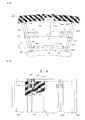
- Fig. 1 is a cross-sectional view showing a central portion of a conventional oscillating vane type pump actuator from in the axial direction.
- Fig. 2 is a sectional view taken along line A-B of Fig. 1 .
- an input/output shaft 6 is installed in the central portion of the oscillating vane type pump actuator.
- a rotor 7 is firmly fixed on the input/output shaft 6 by a key 8.
- a pair of oscillating vanes 7a and 7b are provided on the rotor 7 in a straight line and integrated with the rotor 7 so that sufficient coupling strength therebetween can be ensured.
- a pair of fixed vanes 9a and 9b are firmly fixed by keys 10a and 10b and bolts 24 to a cylinder 3 which encloses the oscillating vanes 7a and 7b.
- a working chamber which increases or reduces in volume comprises four chambers; two chambers are disposed at symmetrical positions on the center axis of the shaft 6 and maintain the same pressure and repeat an increase and reduction in the volume, thus providing the function as an oscillating vane type pump actuator.
- a pair of working chambers 11a and 11b which are disposed at symmetrical positions around the center axis communicate with each other through a connection hole 16.
- the other pair of working chambers 12a and 12b communicate with each other through a connection hole 15.
- the working chambers are connected to all portions of the hydraulic system by pipes 13 and 14 which are disposed around the installation position of the fixed vane 9b.
- Fig. 2 is a longitudinal sectional view showing the oscillating vane type pump actuator.
- a pair of side covers 1 and 2 that have been pointed out as a problem are provided on opposite left and right ends of the actuator.
- the side covers 1 and 2 use bearings 1a and 2a to support the input/output shaft 6 of the oscillating vane type pump actuator at the centers thereof.
- the side covers 1 and 2 are firmly fixed by a plurality of fastening bolts 4 and 5 to the cylinder 3 disposed at the medial portion.
- Fig. 2 is a sectional taken along line A-B, wherein although the oscillating vane 7b has been shown at the left side of Fig. 1 and oriented in the horizontal direction, it is shown at the bottom side in Fig. 2 .
- the cylinder 3 has high strength with respect to the axial direction, that is, the left-right direction of Fig. 2 , and the side covers 1 and 2 have comparatively low strength with respect to the axial direction but have high strength with respect to the radial direction of the center axis.
- the most important problem is that the strength is comparatively low with respect to the radial direction of the center axis. Even if the plate of the cylinder 3 is thick enough to withstand a high pressure of 25Mpa, the entire width of the cylinder 3 is relatively small, so that the radial strength of the cylinder 3 is comparatively low.
- the oscillating vane type pump actuator is used as a main device of a power conversion means of a pendulum type high efficiency wave-power generation apparatus, because pressure is applied in the radial direction to a pressure receiving surface of the cylinder 3 that defines the high-pressure working chambers, the cylinder 3 is distorted into an ellipse-like shape in which the diameter of a portion thereof is increased.
- the four working chambers repeatedly alternate between a high-pressure side and a low-pressure side, and the direction of the ellipse-like distortion also continuously varies as time goes by. Because the side covers 1 and 2 have low axial strength, they are deformed in a shape which is swollen outwards.
- Fig. 3 is a cross-sectional view showing the central portion of a fretting-corrosion-prevention oscillating vane type pump actuator from in the axial direction according to the present invention.
- the construction of the pump actuator of the present invention is almost the same as that of Fig. 1 .
- An input/output shaft 6c that is disposed along the center axis of the oscillating vane type pump actuator is firmly coupled to a rotor 7c by a key 8.
- a pair of oscillating vanes 7c-b and 7c-a are provided on the rotor 7 in the horizontal direction and integrated with the rotor 7 to enhance the coupling strength therebetween.
- a cylinder 3c encloses the oscillating vanes 7c-b and 7c-a.
- a pair of fixed vanes 9a and 9b are fixed at upper and lower positions in the cylinder 3c by respective keys 10c-b and 10c-a and bolts.
- a working chamber which increases and reduces in volume comprises four chambers. Two chambers that are disposed at symmetrical positions on the center axis communicate with each other through a communication hole 15c, and the other two chambers communicate with a communication hole 16c, so that the chambers conduct the same volume variation operation.
- Pipes 14c and 13c are installed around the upper fixed vane 9c-b so that the working chambers are connected to a hydraulic system by the pipes 14c and 13c.
- Fig. 3 shows the cut line C-D to provide a sectional view for the sake of the following description of the present invention.
- Fig. 4 is a sectional view taken along line C-D of Fig. 3 .
- Fig. 4 illustrates the oscillating vane 7c-b at the bottom side although it has been shown at the left side of Fig. 3 as being oriented in the horizontal direction.
- the most important characteristic of the present invention is that the lengths of the opposite left and right ends of the cylinder 3c are shortened, and a cylindrical part is provided on each of the left and right side cover 1c and 2c to compensate for the shortened cylinder, as shown in Fig. 4 .
- a cylindrical part 1c-c that protrudes to the right is integrally provided on the left side cover 1c
- a cylindrical part 2c-c that protrudes to the left is integrally provided on the right side cover 2c.
- Each of the keys 10c-b and 10c-a that fix the fixed vanes 9c-b and 9c-a to the cylinder 3c has the same length as that of the cylinder 3c, and although it is shorter than that of the conventional art, there is no problem in terms of strength.
- the side covers 1c and 2c support the input/output shaft 6c using bearings 1c-a and 2c-a.
- a rotary seal 25 is also provided in the right side cover 2c to prevent oil from leaking out of the bearing 2c-a.
- the left and right side covers 1c and 2c are firmly coupled to the cylinder 3c by a plurality of bolts 4c and 5c.
- Each bolt 4c, 5c is longer than that of the conventional art by the length of the cylindrical part 1c-c, 2c-c of the corresponding side cover.
- the bolts 4c and 5c are preferably made of a material recently commercialized which has superior corrosion resistance against sea water.
- the oscillating vane type pump actuator of the present invention having the basic construction of Fig. 4 , because the elements of the working chambers are firmly joined to each other under pressure, even if distortion is caused by high pressure of work oil that is periodically applied to the working chambers, fretting corrosion can be prevented by the elements that are oriented such that high-strength directions thereof are perpendicular to each other.
- the shapes of the joining surfaces of adjacent elements that are joined to each other under pressure are the same shape.
- the cylindrical parts 1c-c and 2c-c that are provided on the side covers 1c and 2c have the same shape as that of the cylinder 3c so that they can restrict the distortion of the cylinder 3c. Therefore, if the lengths of the cylindrical parts 1c-c and 2c-c are set appropriately, it becomes easy to restrict the strain of distortion such that it is below 20 ⁇ m to 30 ⁇ m, thus coping with fretting corrosion. Further, in the conventional oscillating vane type pump actuator, fretting corrosion also occurs on the joining surfaces between the cylinder 3 and the side covers 1 and 2.
- positions of the portions that are strongly joined to each other by the bolts are spaced apart from each other by the length of the cylindrical parts 1c-c and 2c-2 of the side covers 1c and 2c. Therefore, if the axial length of the fixed vane is set to be slightly shorter than the distance between the side covers without having a mechanical coupling means, the pressure on the junction surfaces can be easily maintained at a lower pressure.
- Fig. 5 is an enlarged right side view showing the joining surface between the side cover 2c and the fixed vane 9c-b to explain in detail the sealing structure of the fixed vane 9c-b.
- the fixed vane 9c-b has two kinds of seals including a seal interposed between fixed members and a seal provided on a slide surface of a slide member. In the former case, because there is no problem with abrasion of the seal, a seal which is made merely by cutting a large diameter 0-ring to a predetermined size can exhibit sufficient sealing effect.
- a 'V'-shaped seal groove and an 0-ring type fixed seals 41c-1 and 41c-2 are provided around the perimeter of the fixed vane 9c-b.
- Fixed seals 40c-1 and 40c-2 are respectively provided around the perimeters of the contact surfaces between the cylinder 3c and the cylindrical part 1c-c and between the cylinder 3c and the cylindrical part 2c-c. Further, a seal groove is formed in the perimeter of the cylindrical rotor 7c in an approximately horizontal direction so that an 0-ring type fixed seal 41-3 is seated into the seal groove. A hole having a diameter greater than the width of the seal groove is formed in the end of each fixed seal in the direction perpendicular to the contact surface, and cylindrical pins 43c-1, 43c-2, 43c-3 and 43c-4 supplement the ends of the fixed seals.
- perimeter grooves having lengths corresponding to the fixed vane 9c are axially formed in a slide surface 19c-b of the center shaft that is a surface in sliding contact with the rotor 7c.
- Slide seals 42c-1 and 42c-2 are provided in the respective perimeter grooves.
- Each of these opposite slide seals has a clamp shape ( ⁇ ), and each of the opposite ends thereof has a lip shape.
- the slide seal can conduct the role of the seal to counteract any pressure applied in the direction in which the angle of the clamp shape is increased, but if the pressure is applied thereto in the direction in which the angle is reduced, the slide seal allows work oil to flow from a high pressure side to a low pressure side. As shown in Fig.
- each of the slide seals 42c-1 and 42c-2 is oriented such that when the pressure in the adjacent working chamber is high, the angle of the clamp shape is reduced.
- a high-pressure side working chamber can always communicate with the slide surface 19c-b between the fixed vane 9c-b and the rotor 7c.
- the present invention has a hydraulic pressure structure wherein the contact surface with the corresponding side cover always communicates with a low-pressure side working chamber, thus preventing excessive contact pressure from being applied to just one of the two sides.
- a pair of check valves 21 and 22 are provided in the center of the fixed vane 9c-b that faces the left and right working chambers 12c-b and 11c-a.
- Each cylindrical pin 43c-1, 43c-2, 43c-3, 43c-4 is made of metal, and the surface thereof is ground to an appropriate degree, so it functions as a seal similar to a piston seal.
- work oil that infiltrates into the contact surfaces 17c and 18c between the fixed vane 9c-b and the side coves through such incomplete seal portions flows out towards a low-pressure side working chamber 12c-b or 11c-b through the check valves 21 and 22, etc. Therefore, the flow rate of work oil in the contact surfaces that are enclosed by the seals provided on the fixed vane 9c-b can be maintained to the minimum flow rate.
- Fig. 6 is a bottom view of the fixed vane 9c-b and partially shows a sectional view taken along line E-F of Fig. 5 . Particularly, in Fig. 6 , the pins 43c-1 and 43c-2 are clearly illustrated by the partially sectional view.
- Each pin 43c-1, 43c-2 has a short cylindrical shape.
- a pin hole that receives each pin is longer than the pin.
- Coil springs 44c-1 and 44c-2 are provided in the lower ends of the pin holes so that the corresponding pins are biased outwards. Compared to the entire length of the fixed vane 9c-b, the length of each pin hole is shorter than that of the fixed vane 9c-b.
- the distance between the pins is preferable for the distance between the pins to be kept to the minimum.
- the distance between the pins can be kept within a range from 1.5 mm to 2 mm.
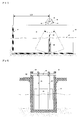
- Figs. 7 and 8 are schematic views showing an example of a high-efficiency pendulum type wave-power generation apparatus using the oscillating vane type pump actuator of the present invention.
- an opening 52 is formed in a portion of a concrete caisson 51 that faces the sea so that waves 47 can be guided into the caisson 51 by the opening 52.
- the left end of the caisson 51 is a fixed wall 53 which reflects waves that enter the caisson 51 from the right side.
- An incident wave that has been reflected by the fixed wall 53 becomes a reverse-directional reflected wave.
- a singular point at which the wave height is always zero and horizontal kinetic energy is doubled, is formed at a position which is 1/4 of the entire wave length.
- An oscillating shaft 49 of the pendulum plate 48 which receives wave-power is disposed at this singular point.
- An oscillating vane pump 50 that uses the present invention is integrally provided on one end of the oscillating shaft 49 to be used as the pump of a generator drive hydraulic system. Because most of the wave energy is applied in the horizontal direction to the vicinity of the pendulum plate 48, the wave power can be efficiently transmitted to the oscillating vane pump 50 via the oscillating shaft 49 and input to the hydraulic system in such a way that it is converted into rotary motion of the generator using high-pressure work oil that flows along pipes 45 and 46.
- Fig. 8 is a schematic view illustrating the caisson of Fig. 7 in the direction from the fixed wall 35 towards the opening 52 so as to facilitate the understanding of the arrangement of the main elements of the apparatus.
- the width of the pendulum plate 48 is slightly less than that of the opening of the concrete caisson 51, and the pendulum plate 48 is attached to a pair of strong support rods 56 and 56'. The upper ends of the support rods 56 and 56' are firmly fixed to the oscillating shaft 49.
- a pair of main bearings 54 are provided on the caisson 51 to support the oscillating shaft.
- the oscillating vane pump 50 of the present invention is integrally coupled to the left end of the oscillating shaft 49.
- the main bearing 54 comprises a spherical bearing having a comparatively large diameter, so that the site work of installing the main elements of the apparatus including the pendulum plate and the main shaft on the caisson 51 can be facilitated, thus reducing the working time.
- Fig. 9 illustrates an example in which the oscillating vane type pump actuator of the present invention is used as an actuator for driving a steering device of a large ship.
- Fig. 9 is a sectional view of a lower portion of the stern of the ship. Because the space in the ship is limited and the actuator 60 for the rudder 62 requires a large amount of oscillating power, using the oscillating vane type pump actuator of the present invention as the actuator 60 can optimize the design of the peripheral elements. If the actuator 60 is directly connected to a main rudder shaft 61, regardless of the oscillating position of the rudder 62, the rate of variation in the flow rate of work oil always coincides with the rate of variation of the angle of the rudder 62.
- the structure wherein the rudder 62 and the actuator 60 are directly connected to each other using the main rudder shaft 61 makes the responsivity between the rudder 62 and the actuator 60 superior.
- the actuator is of high pressure of 25Mpa, it realizes a very compact steering device, thus making better use of space in the ship, and being more economical.
- the oscillating vane type pump actuator of the present invention can lead to a low-cost mass production system, high economic effects resulting from exploitation of a new market are also expected. Moreover, in the hydraulic machine industry which has been reduced by the trend to favor energy-saving technology, a high power compact oscillating vane actuator for oscillation-driving a hinge unit of a large robot for high-rise work, which has not been able to be realized by the conventional technology, can be realized. Therefore the present invention can be a new technology which counteracts the shrinking of the market.
Landscapes
- Engineering & Computer Science (AREA)
- Mechanical Engineering (AREA)
- General Engineering & Computer Science (AREA)
- Physics & Mathematics (AREA)
- Fluid Mechanics (AREA)
- Chemical & Material Sciences (AREA)
- Combustion & Propulsion (AREA)
- Thermal Sciences (AREA)
- Actuator (AREA)
- Hydraulic Motors (AREA)
- Details And Applications Of Rotary Liquid Pumps (AREA)
- Rotary Pumps (AREA)
Abstract
Description
- The present invention relates, in general, to oscillating vane type pump actuators which realize a high power oscillating drive using high-pressure work oil as a power conversion means and, more particularly, to an improved high-pressure oscillating vane type pump actuator which can provide effective measures to solve problems caused in an apparatus which has proved the efficiency of the wave-power generation to be markedly enhanced using an oscillating vane type pump actuator that can be used in high pressure of 25Mpa.
- The inventor of the present invention has strived to develop wave-power generation systems having high energy efficiency from when he worked at the Muroran Industry College of Japan. In detail, it pertains to using wave power having two kinds of complex motion mechanisms including vertical and horizontal motions. An oscillating plate is installed at a singular point at which interference between incident waves and reflected waves occurs, particularly, at a singular point
- at which vertical motion becomes zero while horizontal kinetic energy is doubled. Thereby, it is intended to provide a rational wave-power generation method, in particular, a pendulum wave-power generation method in which a generator using a hydraulic system can be efficiently operated.
- In Japan, there are not many engineers who try to actively understand and use wave interference which is one of the fundamental notions of physics and has been disclosed in
Patent document 1. Thus, there are very few people who recognize the achievements of the research of the inventor of the present invention. With regard to this, on the open sea, the energy efficiency of a practical apparatus using the high efficiency wave-power generation method was about 42% which is the world's highest. - The first practical apparatus to be manufactured by the inventor of the present invention as a hydraulic pump device for converting oscillating motion of the pendulum plate into rotary motion of a generator was a system using a large hydraulic cylinder. However, when the hydraulic cylinder is used, the power of impacting waves is applied to the pendulum plate and may cause fatigue failure of a cylinder mounting member or hinge pin. Further, in severe conditions of the open sea, a lubricant unit may malfunction. Therefore, to avoid the above problems, a simple power conversion mechanism which can withstand the severe natural conditions and has no dispensable member is required. A solution for this is to provide an oscillating vane type pump actuator which is integrally provided on an oscillating shaft of the pendulum plate and to limit the members which must maintain lubricating performance in the midst of severe natural conditions to a pair of bearings which support the oscillating shaft of the pendulum plate. In the case of the bearings, it is easy to maintain the lubricant performance. Mounting members integrated with the bearings are also strong. Thus, most of the problems can be solved. However, because the pressure resistance of oscillating vane pumps which have been commercialized is typically low, it is necessary to increase the pressure resistance two or three fold. The inventor of the present invention has also striven to solve such problems and has proposed a detailed technique of
Patent document 2 which can be used even in pressure of 25Mpa. As a result, the inventor of the present invention realized the development of a hydraulic high power conversion apparatus which is compact and has superior durability even in severe sea conditions. Moreover, based on such achievements, it has become increasingly possible for a large oscillating vane type pump actuator having specifications for high-pressure to also be used in a wave-power generation method using motion of a floating body, which has recently been attracting attention. - Typically, conventional hydraulic systems have simple valve structures which can control high power but consume a lot of energy. Recently, the age of technological innovation which highly evaluates energy saving technology has come about, so the hydraulic systems have changed into an electric-powered structure, and there has been a reduction in the market for hydraulic systems. Here, an advancement into new fields which has not been achieved by the conventional technology will be one of the best ways to counteract the shrinking of the market. A representative example of this is an oscillating actuator which can be used in a hinge unit of a large robot arm. For example, this can be used in a high-rise work for construction of a large windmill which uses natural energy. In the construction work of the large windmill, it is difficult to use an electric-powered structure, because the output of an electric motor is typically not sufficient.
- As another field in which it is expected to be able to use the high-pressure oscillating vane actuator, the actuator may be used as an oscillating actuator for a steering device of a large ship. However, the oscillating vane actuator which is available on the market is a low pressure/small capacity actuator of 14Mpa or less and cannot meet requirements of the shipbuilding or shipping industry which pursue minimization of space required to install the actuator.
- Accordingly, the present invention has been made keeping in mind the above problems occurring in the prior art, and an object of the present invention is to provide an oscillating vane type pump actuator which has an improved structure that can prevent the abrasion of mounting surfaces of main elements and, more particularly, to prevent fretting corrosion on junction surfaces between a cylinder and side covers that define the hydraulic working chamber of the oscillating vane type pump actuator and on contact surfaces between a fixed vane provided on the cylinder and the side covers.
- The reason the above problems occur is believed to be that the axial strength and radial strength of the cylinder are inversely related to those of the disk-like side covers, so that the difference in torsion on the junctions between the cylinder and the side covers that is caused by high-pressure of work oil applied to the working chamber is comparatively large. In other words, it is believed that there is a difference in directional strength between the cylinder and the side covers, that is, the cylinder has high axial strength but low radial strength, while each disk-like side cover has high radial strength but low axial strength, and that this is the fundamental cause of the problems.
- [Patent document 1] Japanese Patent No.
2001-271735 2000-128632 - [Patent document 2] Japanese Patent No.
2002-168180 2000-403806 - In order to accomplish the above object, the present invention is configured such that the lengths of opposite ends of a cylinder are shortened and a cylindrical part that protrudes towards the cylinder is provided on each side cover to make up for the shortened cylinder. Furthermore, at junction surfaces between a fixed vane and the side covers, to mitigate excessive pressure applied to the junction surfaces, a passage that always communicates with a low-pressure side working chamber is formed in the surface that is enclosed by a seal provided on a joined surface of the fixed vane that is joined to each side cover. Thus, the side covers and the fixed vane are put into contact with each other by oil films at pressures lower than that of the conventional technology, thereby allowing deformation attributable to a relative distortion direction difference.
- According to the present invention, the cylinder is shorter than that of the conventional technology, and a cylindrical part is provided on each side cover to make up for the shortened cylinder. Therefore, on the junction between the cylinder and the side covers that have different directional strengths and are coupled to each other by bolts or the like, even when high pressure applied into the working chamber causes ellipse-like distortion of the cylinder, the surfaces of the side covers that are joined to the cylinder are distorted in the same manner as that of the cylinder unlike the form of distortion of the side cover body, because the cylindrical part has the same shape as that of the cylinder. In the present invention, the relative distortion rate of the cylinder and the side covers can be limited to 20 µm to 30 µm, so that the fretting corrosion on the junction surfaces between them can be reliably prevented.
- The same pressure can be maintained over the entire area of a contact surface between a fixed vane and the cylinder to which the fixed vane is fixed by a bolt or key, as well as contact surfaces between the fixed vane and the side covers, thanks to the use of a passage that communicates with the working chambers. In the passage, a check valve prevents a high-pressure side working chamber from communicating with the passage and allows a low-pressure side working chamber from communicating with the passage, so that a low pressure state can always be maintained, and the contact surfaces between the side covers and the fixed vane are brought contact with each other by a thin oil film. As a result, even if there is a difference in relative distortion between them, stress applied to the contact surfaces in the direction of the distortion is relatively low, thus preventing fretting corrosion that may be caused by fine oscillation between the elements that are strongly joined to each other.
-
-
Fig. 1 is a cross-sectional view showing a central portion of a conventional oscillating vane type pump actuator from in the axial direction. -
Fig. 2 is a longitudinal sectional view showing the conventional oscillating vane type pump actuator. -
Fig. 3 is a cross-sectional view showing a central portion of an oscillating vane type pump actuator from in the axial direction, according to the present invention. -
Fig. 4 is a sectional view taken along line C-D ofFig. 3 . -
Fig. 5 is an enlarged front view showing a joining surface between a right side cover and a fixed vane ofFig. 4 ; -
Fig. 6 is a bottom view of the fixed vane ofFig. 5 and partially shows a sectional view taken along line E-F ofFig. 5 . -
Fig. 7 is a side schematic view showing an example in which the present invention is used in a pendulum type wave-power generating apparatus which can generate power at high-efficiency. -
Fig. 8 is a schematic view showing the wave-power generating apparatus ofFig. 7 from the left-right direction. -
Fig. 9 is a schematic view showing an example in which the present invention is used in a rudder control device of a large ship. -
- 1, 2: side cover of conventional oscillating vane type pump actuator
- 1a, 2a: bearing of oscillating shaft of conventional oscillating vane type pump actuator
- 1d, 2d: contact surface between side covers and a cylinder of a conventional oscillating vane type pump actuator
- 3: cylinder of conventional oscillating vane type pump actuator
- 4, 5: side cover/cylinder connection bolts of conventional oscillating vane type pump actuator
- 6: oscillating shaft of conventional oscillating vane type pump actuator
- 7: rotor of conventional oscillating vane type pump actuator
- 7a, 7b: oscillating vane of conventional oscillating vane type pump actuator
- 8: rotor shaft key of conventional oscillating vane type pump actuator
- 9a, 9b: fixed vane of conventional oscillating vane type pump actuator
- 10a, 10b: key for fixed vane of conventional oscillating vane type pump actuator
- 11a, 11b: a pair of working chambers connected to each other by a connection hole in a conventional oscillating vane type pump actuator
- 12a, 12b: another pair of working chambers connected to each other by a connection hole in a conventional oscillating vane type pump actuator
- 13, 14: pipes connecting working chambers that increase and reduce in volume in a hydraulic system in a conventional oscillating vane type pump actuator
- 15, 16: connection hole communicating interlocking working chambers with each other in a conventional oscillating vane type pump actuator
- 17, 18: contact surface between side cover and fixed vane of a conventional oscillating vane type pump actuator
- 1c, 2c: side cover of oscillating vane type pump actuator of the present invention
- 1c-a, 2c-a: bearing of oscillating shaft of oscillating vane type pump actuator of the present invention
- 1c-c, 2c-c: cylindrical part of side cover of oscillating vane type pump actuator of the present invention
- 1c-d, 2c-d: contact surface between cylinder and cylindrical part of side cover of the present invention
- 3c: cylinder of an oscillating vane type pump actuator of the present invention
- 4c, 5c: connection bolt of cylinder and side cover
- 6c: oscillating shaft of an oscillating vane type pump actuator of the present invention
- 7c: rotor of an oscillating vane type pump actuator of the present invention
- 7c-a, 7c-b: oscillating vane of an oscillating vane type pump actuator of the present invention
- 8c: rotor shaft key of the present invention
- 9c-a, 9c-b: fixed vane of an oscillating vane type pump actuator of the present invention
- 10c-a, 10c-b: key of fixed vane of the present invention
- 11c-a, 11c-b: a pair of interlocking working chambers of an oscillating vane type pump actuator of the present invention
- 12c-a, 12c-b: another pair of interlocking working chambers of an oscillating vane type pump actuator of the present invention
- 13c, 14c: pipes connecting working chambers that increase and reduce in volume in a hydraulic system according to the present invention
- 15c, 16c: connection hole communicating interlocking working chambers with each other according to the present invention
- 17c, 18c: contact surface between a side cover and fixed vane of the present invention
- 19c-a, 19c-b: slide surface between a rotor and fixed vane of the present invention
- 20c-a, 20c-b: contact surface between a cylinder and fixed vane of the present invention
- 21, 22: check valve provided in a fixed vane of the present invention
- 23: passage passing through opposite side surface of a fixed vane in contact with side covers according to the present invention
- 24: mounting bolt of a fixed vane
- 25: rotary seal
- 40c-1, 40c-2: fixed seal provided between cylinder and a fixed vane according to the present invention
- 41c-1, 41c-2, 41c-3: fixed seal provided on contact surface of side cover installed on a fixed vane according to the present invention
- 42c-1, 42c-2: rotor slide seal provided on a fixed vane according to the present invention
- 43c-1, 43c-2, 43c-3, 43c-4: fixed seal end pin of contact surface of a side cover of fixed vane according to the present invention
- 44c-1, 44c-2: coil spring compressing fixed seal end pin of fixed vane according to the present invention
- 45, 46: connection pipe between oscillating vane pump and hydraulic system in example in which an oscillating vane type pump actuator of the present invention is used in a pendulum type wave-power generating apparatus
- 47: wave surface
- 48: pendulum plate receiving wave power in a pendulum type wave-power generating apparatus
- 49: oscillating shaft bearing of a pendulum type wave-power generating apparatus
- 50: oscillating vane pump of an example in which an oscillating vane type pump actuator of the present invention is used in wave-power generating apparatus
- 51: concrete caisson of a pendulum type wave-power generating apparatus
- 52: opening of caisson
- 53: fixed wall of caisson
- 54: spherical bearing of oscillating shaft of wave-power generating apparatus
- 55: bearing of oscillating shaft of wave-power generating apparatus
- 56, 56': support rod connecting pendulum plate to oscillating shaft of pendulum type wave-power generating apparatus
- 60: actuator of example in which oscillating vane type pump actuator of the present invention is used to control rudder of large ship
- 61: main rudder shaft
- 62: rudder
- Hereinafter, the present invention will be described in detail with reference to the attached drawings.
-
Fig. 1 is a cross-sectional view showing a central portion of a conventional oscillating vane type pump actuator from in the axial direction.Fig. 2 is a sectional view taken along line A-B ofFig. 1 . As shown inFig. 1 , an input/output shaft 6 is installed in the central portion of the oscillating vane type pump actuator. Arotor 7 is firmly fixed on the input/output shaft 6 by a key 8. A pair of oscillatingvanes rotor 7 in a straight line and integrated with therotor 7 so that sufficient coupling strength therebetween can be ensured. A pair of fixedvanes keys bolts 24 to acylinder 3 which encloses theoscillating vanes chambers connection hole 16. The other pair of workingchambers connection hole 15. The working chambers are connected to all portions of the hydraulic system bypipes vane 9b. -
Fig. 2 is a longitudinal sectional view showing the oscillating vane type pump actuator. A pair of side covers 1 and 2 that have been pointed out as a problem are provided on opposite left and right ends of the actuator. The side covers 1 and 2use bearings fastening bolts cylinder 3 disposed at the medial portion.Fig. 2 is a sectional taken along line A-B, wherein although theoscillating vane 7b has been shown at the left side ofFig. 1 and oriented in the horizontal direction, it is shown at the bottom side inFig. 2 . In the conventional oscillating vane type pump actuator having the above-mentioned basic construction, thecylinder 3 has high strength with respect to the axial direction, that is, the left-right direction ofFig. 2 , and the side covers 1 and 2 have comparatively low strength with respect to the axial direction but have high strength with respect to the radial direction of the center axis. The most important problem is that the strength is comparatively low with respect to the radial direction of the center axis. Even if the plate of thecylinder 3 is thick enough to withstand a high pressure of 25Mpa, the entire width of thecylinder 3 is relatively small, so that the radial strength of thecylinder 3 is comparatively low. Therefore, if the oscillating vane type pump actuator is used as a main device of a power conversion means of a pendulum type high efficiency wave-power generation apparatus, because pressure is applied in the radial direction to a pressure receiving surface of thecylinder 3 that defines the high-pressure working chambers, thecylinder 3 is distorted into an ellipse-like shape in which the diameter of a portion thereof is increased. When a pendulum plate is oscillated by wave power, the four working chambers repeatedly alternate between a high-pressure side and a low-pressure side, and the direction of the ellipse-like distortion also continuously varies as time goes by. Because the side covers 1 and 2 have low axial strength, they are deformed in a shape which is swollen outwards. Thereby, the side covers 1 and 2 are slightly reduced in diameter contrary to thecylinder 3 which is distorted into an ellipse-like shape. As a result, after the actuator has been operated for a long period of time, fretting corrosion occurs on acontact surface 17a between theside cover 1 and the fixedvanes contact surface 18a between theside cover 2 and the fixedvanes cylinder 3 to the side covers 1 and 2 that have high radial strength will restrict the ellipse-like distortion of thecylinder 3, even if the coupling force among them is enhanced by thebolts cylinder 3 that protrude outwards from the circumferential outer surface of the cylinder are coupled to the side covers 1 and 2. Therefore, this method is not effective at restricting the distortion, which ranges from 200 µm to 300 µm, to within the target range of several µm or less. -
Fig. 3 is a cross-sectional view showing the central portion of a fretting-corrosion-prevention oscillating vane type pump actuator from in the axial direction according to the present invention. The construction of the pump actuator of the present invention is almost the same as that ofFig. 1 . An input/output shaft 6c that is disposed along the center axis of the oscillating vane type pump actuator is firmly coupled to arotor 7c by a key 8. A pair of oscillatingvanes 7c-b and 7c-a are provided on therotor 7 in the horizontal direction and integrated with therotor 7 to enhance the coupling strength therebetween. Acylinder 3c encloses theoscillating vanes 7c-b and 7c-a. A pair of fixedvanes cylinder 3c byrespective keys 10c-b and 10c-a and bolts. A working chamber which increases and reduces in volume comprises four chambers. Two chambers that are disposed at symmetrical positions on the center axis communicate with each other through acommunication hole 15c, and the other two chambers communicate with acommunication hole 16c, so that the chambers conduct the same volume variation operation.Pipes 14c and 13c are installed around the upper fixedvane 9c-b so that the working chambers are connected to a hydraulic system by thepipes 14c and 13c.Fig. 3 shows the cut line C-D to provide a sectional view for the sake of the following description of the present invention. -
Fig. 4 is a sectional view taken along line C-D ofFig. 3 . In the same manner asFig. 2 ,Fig. 4 illustrates theoscillating vane 7c-b at the bottom side although it has been shown at the left side ofFig. 3 as being oriented in the horizontal direction. The most important characteristic of the present invention is that the lengths of the opposite left and right ends of thecylinder 3c are shortened, and a cylindrical part is provided on each of the left andright side cover Fig. 4 . In detail, acylindrical part 1c-c that protrudes to the right is integrally provided on theleft side cover 1c, and acylindrical part 2c-c that protrudes to the left is integrally provided on theright side cover 2c. Each of thekeys 10c-b and 10c-a that fix the fixedvanes 9c-b and 9c-a to thecylinder 3c has the same length as that of thecylinder 3c, and although it is shorter than that of the conventional art, there is no problem in terms of strength. The side covers 1c and 2c support the input/output shaft 6c usingbearings 1c-a and 2c-a. Arotary seal 25 is also provided in theright side cover 2c to prevent oil from leaking out of the bearing 2c-a. The left and right side covers 1c and 2c are firmly coupled to thecylinder 3c by a plurality ofbolts bolt cylindrical part 1c-c, 2c-c of the corresponding side cover. Thebolts - In the oscillating vane type pump actuator of the present invention having the basic construction of
Fig. 4 , because the elements of the working chambers are firmly joined to each other under pressure, even if distortion is caused by high pressure of work oil that is periodically applied to the working chambers, fretting corrosion can be prevented by the elements that are oriented such that high-strength directions thereof are perpendicular to each other. In the present invention, the shapes of the joining surfaces of adjacent elements that are joined to each other under pressure are the same shape. Thus, even if the oscillation of theoscillating vanes 7c-b and 7c-a in the working chamber induces a slight ellipse-like distortion of thecylinder 3c, thecylindrical parts 1c-c and 2c-c that are provided on the side covers 1c and 2c have the same shape as that of thecylinder 3c so that they can restrict the distortion of thecylinder 3c. Therefore, if the lengths of thecylindrical parts 1c-c and 2c-c are set appropriately, it becomes easy to restrict the strain of distortion such that it is below 20 µm to 30 µm, thus coping with fretting corrosion. Further, in the conventional oscillating vane type pump actuator, fretting corrosion also occurs on the joining surfaces between thecylinder 3 and the side covers 1 and 2. However, in the present invention, positions of the portions that are strongly joined to each other by the bolts are spaced apart from each other by the length of thecylindrical parts 1c-c and 2c-2 of the side covers 1c and 2c. Therefore, if the axial length of the fixed vane is set to be slightly shorter than the distance between the side covers without having a mechanical coupling means, the pressure on the junction surfaces can be easily maintained at a lower pressure. -
Fig. 5 is an enlarged right side view showing the joining surface between theside cover 2c and the fixedvane 9c-b to explain in detail the sealing structure of the fixedvane 9c-b. The fixedvane 9c-b has two kinds of seals including a seal interposed between fixed members and a seal provided on a slide surface of a slide member. In the former case, because there is no problem with abrasion of the seal, a seal which is made merely by cutting a large diameter 0-ring to a predetermined size can exhibit sufficient sealing effect. A 'V'-shaped seal groove and an 0-ring type fixedseals 41c-1 and 41c-2 are provided around the perimeter of the fixedvane 9c-b.Fixed seals 40c-1 and 40c-2 are respectively provided around the perimeters of the contact surfaces between thecylinder 3c and thecylindrical part 1c-c and between thecylinder 3c and thecylindrical part 2c-c. Further, a seal groove is formed in the perimeter of thecylindrical rotor 7c in an approximately horizontal direction so that an 0-ring type fixed seal 41-3 is seated into the seal groove. A hole having a diameter greater than the width of the seal groove is formed in the end of each fixed seal in the direction perpendicular to the contact surface, andcylindrical pins 43c-1, 43c-2, 43c-3 and 43c-4 supplement the ends of the fixed seals. Furthermore, perimeter grooves having lengths corresponding to the fixedvane 9c are axially formed in aslide surface 19c-b of the center shaft that is a surface in sliding contact with therotor 7c. Slide seals 42c-1 and 42c-2 are provided in the respective perimeter grooves. Each of these opposite slide seals has a clamp shape (<), and each of the opposite ends thereof has a lip shape. The slide seal can conduct the role of the seal to counteract any pressure applied in the direction in which the angle of the clamp shape is increased, but if the pressure is applied thereto in the direction in which the angle is reduced, the slide seal allows work oil to flow from a high pressure side to a low pressure side. As shown inFig. 5 , each of the slide seals 42c-1 and 42c-2 is oriented such that when the pressure in the adjacent working chamber is high, the angle of the clamp shape is reduced. Thus, a high-pressure side working chamber can always communicate with theslide surface 19c-b between the fixedvane 9c-b and therotor 7c. - Although the above-described seal structure of the fixed
vane 9c-b is almost the same as that ofPatent document 2, the present invention has a hydraulic pressure structure wherein the contact surface with the corresponding side cover always communicates with a low-pressure side working chamber, thus preventing excessive contact pressure from being applied to just one of the two sides. As shown by the dashed line ofFig. 5 , a pair ofcheck valves vane 9c-b that faces the left and right workingchambers 12c-b and 11c-a. Apassage 23, through which contact surfaces 17c and 18c between the fixed vane and the side covers communicate with each other, is formed through the fixed vane. Further, thepassage 23 includes passages which communicate with thecheck valves Fig. 5 , space that is not completely sealed is formed between theslide seal 42c-1 and thepin 43c-1 which are close to each other and between theslide seal 42c-2 and thepin 43c-1 which are close to each other. Further, space between thepins 43c-1 and 43c-2 cannot be completely sealed. However, because theside cover vane 9c-b are assembled such that a distance between the fixedvane 9c-b and eachside cover cylindrical pin 43c-1, 43c-2, 43c-3, 43c-4 is made of metal, and the surface thereof is ground to an appropriate degree, so it functions as a seal similar to a piston seal. However, work oil that infiltrates into the contact surfaces 17c and 18c between the fixedvane 9c-b and the side coves through such incomplete seal portions flows out towards a low-pressureside working chamber 12c-b or 11c-b through thecheck valves vane 9c-b can be maintained to the minimum flow rate. -
Fig. 6 is a bottom view of the fixedvane 9c-b and partially shows a sectional view taken along line E-F ofFig. 5 . Particularly, inFig. 6 , thepins 43c-1 and 43c-2 are clearly illustrated by the partially sectional view. Eachpin 43c-1, 43c-2 has a short cylindrical shape. A pin hole that receives each pin is longer than the pin. Coil springs 44c-1 and 44c-2 are provided in the lower ends of the pin holes so that the corresponding pins are biased outwards. Compared to the entire length of the fixedvane 9c-b, the length of each pin hole is shorter than that of the fixedvane 9c-b. Thus, to minimize the area of portions which are not sealed by the fixedseals 41c-1 and 41c-3 and thepin 43c-1 or 43c-2, etc., it is preferable for the distance between the pins to be kept to the minimum. In detail, the distance between the pins can be kept within a range from 1.5 mm to 2 mm. -
Figs. 7 and 8 are schematic views showing an example of a high-efficiency pendulum type wave-power generation apparatus using the oscillating vane type pump actuator of the present invention. - As shown in the right side of
Fig. 7 , anopening 52 is formed in a portion of aconcrete caisson 51 that faces the sea so thatwaves 47 can be guided into thecaisson 51 by theopening 52. The left end of thecaisson 51 is a fixedwall 53 which reflects waves that enter thecaisson 51 from the right side. An incident wave that has been reflected by the fixedwall 53 becomes a reverse-directional reflected wave. As a result of interference between the incident waves and the reflected waves, a singular point, at which the wave height is always zero and horizontal kinetic energy is doubled, is formed at a position which is 1/4 of the entire wave length. Anoscillating shaft 49 of thependulum plate 48 which receives wave-power is disposed at this singular point. Anoscillating vane pump 50 that uses the present invention is integrally provided on one end of theoscillating shaft 49 to be used as the pump of a generator drive hydraulic system. Because most of the wave energy is applied in the horizontal direction to the vicinity of thependulum plate 48, the wave power can be efficiently transmitted to theoscillating vane pump 50 via the oscillatingshaft 49 and input to the hydraulic system in such a way that it is converted into rotary motion of the generator using high-pressure work oil that flows alongpipes -
Fig. 8 is a schematic view illustrating the caisson ofFig. 7 in the direction from the fixed wall 35 towards the opening 52 so as to facilitate the understanding of the arrangement of the main elements of the apparatus. The width of thependulum plate 48 is slightly less than that of the opening of theconcrete caisson 51, and thependulum plate 48 is attached to a pair ofstrong support rods 56 and 56'. The upper ends of thesupport rods 56 and 56' are firmly fixed to theoscillating shaft 49. A pair ofmain bearings 54 are provided on thecaisson 51 to support the oscillating shaft. Theoscillating vane pump 50 of the present invention is integrally coupled to the left end of theoscillating shaft 49. Themain bearing 54 comprises a spherical bearing having a comparatively large diameter, so that the site work of installing the main elements of the apparatus including the pendulum plate and the main shaft on thecaisson 51 can be facilitated, thus reducing the working time. -
Fig. 9 illustrates an example in which the oscillating vane type pump actuator of the present invention is used as an actuator for driving a steering device of a large ship.Fig. 9 is a sectional view of a lower portion of the stern of the ship. Because the space in the ship is limited and theactuator 60 for therudder 62 requires a large amount of oscillating power, using the oscillating vane type pump actuator of the present invention as theactuator 60 can optimize the design of the peripheral elements. If theactuator 60 is directly connected to amain rudder shaft 61, regardless of the oscillating position of therudder 62, the rate of variation in the flow rate of work oil always coincides with the rate of variation of the angle of therudder 62. Further, the structure wherein therudder 62 and theactuator 60 are directly connected to each other using themain rudder shaft 61 makes the responsivity between therudder 62 and theactuator 60 superior. In addition, because the actuator is of high pressure of 25Mpa, it realizes a very compact steering device, thus making better use of space in the ship, and being more economical. Even if a high-pressure hydraulic cylinder which is being sold in the market is used as the actuator, the flow rate of work oil that is required to change the angle of the rudder to a predetermined angle may become different, and because there is a difference in the volume of the working chamber between when manipulating the rudder in the clockwise direction and the counterclockwise direction, precise control of the pressure and flow rate is required, thus making a control system complex. Although advantages of the use of oscillating vane type pump actuators in steering devices have been well known and the expectations regarding commercialization have been high, a product having specifications for high-pressure has not been commercialized. If the oscillating vane type pump actuator of the present invention can lead to a low-cost mass production system, high economic effects resulting from exploitation of a new market are also expected. Moreover, in the hydraulic machine industry which has been reduced by the trend to favor energy-saving technology, a high power compact oscillating vane actuator for oscillation-driving a hinge unit of a large robot for high-rise work, which has not been able to be realized by the conventional technology, can be realized. Therefore the present invention can be a new technology which counteracts the shrinking of the market.
Claims (2)
- A fretting-corrosion-prevention oscillating vane type pump actuator, comprising:a cylinder;a pair of side covers provided on opposite ends of the cylinder;an oscillating shaft supported by central portions of the pair of side covers, the oscillating shaft protruding outwards from one side cover;a fixed rotor fitted over the oscillating shaft;an oscillating vane integrated on the rotor; anda fixed vane fixed to the cylinder and brought into close contact with the cylinder and the pair of side covers by fixed seals, the fixed vane having a slide surface that makes contact with a circumferential outer surface of the cylinder by means of a slide seal,wherein the cylinder is shorter at opposite ends thereof than a length of the rotor, the opposite ends being shorter by a same length, andthe pair of side covers are integrated with respective cylindrical parts which extend inwards by a same length by which the lengths of the opposite ends of the cylinder are shortened, to compensate for the shorter length of the cylinder.
- The fretting-corrosion-prevention oscillating vane type pump actuator according to claim 1, wherein a passage passing through the fixed vane is open on junction surfaces between the fixed vane and the opposite side covers, and
a pair of check valves passing through the passage are installed towards opposite working chambers having opposing hydraulic pressures, each of the pair of check valves being oriented in a direction which prevents communication with the working chamber at a high pressure side and allows communication with the working chamber at a low pressure side.
Applications Claiming Priority (3)
| Application Number | Priority Date | Filing Date | Title |
|---|---|---|---|
| JP2010108717A JP5614093B2 (en) | 2010-04-17 | 2010-04-17 | Swing vane type pump / actuator compatible with fretting corrosion |
| KR1020110033138A KR101155582B1 (en) | 2010-04-17 | 2011-04-11 | Swing Vane Type Pump Actuator for Preventing Fretting Corrosion |
| PCT/KR2011/002686 WO2011129642A2 (en) | 2010-04-17 | 2011-04-14 | Swing vane-type pump actuator which prevents fretting corrosion |
Publications (3)
| Publication Number | Publication Date |
|---|---|
| EP2562421A2 true EP2562421A2 (en) | 2013-02-27 |
| EP2562421A4 EP2562421A4 (en) | 2016-04-20 |
| EP2562421B1 EP2562421B1 (en) | 2017-03-29 |
Family
ID=45030519
Family Applications (1)
| Application Number | Title | Priority Date | Filing Date |
|---|---|---|---|
| EP11769108.9A Active EP2562421B1 (en) | 2010-04-17 | 2011-04-14 | Swing vane-type pump actuator which prevents fretting corrosion |
Country Status (7)
| Country | Link |
|---|---|
| US (1) | US8899948B2 (en) |
| EP (1) | EP2562421B1 (en) |
| JP (1) | JP5614093B2 (en) |
| KR (1) | KR101155582B1 (en) |
| CN (1) | CN102859197B (en) |
| DK (1) | DK2562421T3 (en) |
| WO (1) | WO2011129642A2 (en) |
Cited By (1)
| Publication number | Priority date | Publication date | Assignee | Title |
|---|---|---|---|---|
| PL424565A1 (en) * | 2018-02-12 | 2019-08-26 | Politechnika Łódzka | Pneumatic actuator |
Families Citing this family (8)
| Publication number | Priority date | Publication date | Assignee | Title |
|---|---|---|---|---|
| EP2703644B1 (en) * | 2012-08-27 | 2016-08-03 | Alstom Wind, S.L.U. | Angular positioning system for a wind turbine |
| CN103850867B (en) * | 2014-03-05 | 2016-01-20 | 天津大学 | Float type wave energy hydraulic pressure generating system |
| CN105864140A (en) * | 2016-05-26 | 2016-08-17 | 江苏兰格特自动化设备有限公司 | 90-degree-angle stroke hydraulic and pneumatic driving actuator |
| CN107740766B (en) * | 2017-09-30 | 2020-12-01 | 山东海伦食品有限公司 | Swing structure constant speed air compressor machine |
| KR101976615B1 (en) | 2017-12-12 | 2019-05-09 | 유원산업(주) | Rotary vane pump for wave power plant |
| CN108150477A (en) * | 2017-12-25 | 2018-06-12 | 武汉科技大学 | Engineering machinery based on oscillating oil cylinder |
| CN111828720A (en) * | 2020-08-14 | 2020-10-27 | 江苏易恒自动化设备有限公司 | A gas-liquid linkage actuator and gas-liquid linkage control system |
| WO2022115665A1 (en) * | 2020-11-27 | 2022-06-02 | Paul Anthony Johnson | Material mover |
Family Cites Families (13)
| Publication number | Priority date | Publication date | Assignee | Title |
|---|---|---|---|---|
| US4027475A (en) * | 1974-10-29 | 1977-06-07 | Advanced Power Systems | Power systems |
| JPS63174588U (en) | 1986-12-03 | 1988-11-11 | ||
| JPH02245493A (en) * | 1989-03-20 | 1990-10-01 | Hitachi Ltd | Screw vacuum pump |
| JP2539742B2 (en) * | 1993-06-30 | 1996-10-02 | 社団法人寒地港湾技術研究センター | Pendulum type wave power generator |
| JP3687011B2 (en) * | 1995-10-31 | 2005-08-24 | 社団法人寒地港湾技術研究センター | Seal structure of oscillating vane pump |
| JP4140796B2 (en) | 1998-10-26 | 2008-08-27 | Tdk株式会社 | Piezoelectric ceramics |
| JP2001271735A (en) | 2000-03-24 | 2001-10-05 | Tomiji Watabe | Caisson shortened pendulum type wave power generator |
| JP4159241B2 (en) * | 2000-11-30 | 2008-10-01 | 株式会社デンソー | Valve timing adjusting device for internal combustion engine |
| JP2002168180A (en) | 2000-12-02 | 2002-06-14 | Tomiji Watabe | Swing vane type pump / actuator |
| JP3814261B2 (en) | 2003-05-14 | 2006-08-23 | 江口産業株式会社 | Vane pump |
| JP2005307821A (en) | 2004-04-20 | 2005-11-04 | Toyota Motor Corp | Vane type hydraulic motor |
| DE112007001338T5 (en) * | 2006-06-02 | 2009-04-23 | Mathers, Norman Ian, Bridgeman Downs | Rotary vane pump for pumping hydraulic fluid |
| JP4712827B2 (en) * | 2008-05-22 | 2011-06-29 | 日立オートモティブシステムズ株式会社 | Variable displacement vane pump |
-
2010
- 2010-04-17 JP JP2010108717A patent/JP5614093B2/en active Active
-
2011
- 2011-04-11 KR KR1020110033138A patent/KR101155582B1/en active Active
- 2011-04-14 CN CN201180019391.6A patent/CN102859197B/en active Active
- 2011-04-14 DK DK11769108.9T patent/DK2562421T3/en active
- 2011-04-14 US US13/512,545 patent/US8899948B2/en active Active
- 2011-04-14 EP EP11769108.9A patent/EP2562421B1/en active Active
- 2011-04-14 WO PCT/KR2011/002686 patent/WO2011129642A2/en not_active Ceased
Non-Patent Citations (1)
| Title |
|---|
| See references of WO2011129642A2 * |
Cited By (1)
| Publication number | Priority date | Publication date | Assignee | Title |
|---|---|---|---|---|
| PL424565A1 (en) * | 2018-02-12 | 2019-08-26 | Politechnika Łódzka | Pneumatic actuator |
Also Published As
| Publication number | Publication date |
|---|---|
| WO2011129642A3 (en) | 2012-01-05 |
| JP5614093B2 (en) | 2014-10-29 |
| KR20110116090A (en) | 2011-10-25 |
| CN102859197B (en) | 2015-05-27 |
| US20120237384A1 (en) | 2012-09-20 |
| WO2011129642A2 (en) | 2011-10-20 |
| EP2562421B1 (en) | 2017-03-29 |
| CN102859197A (en) | 2013-01-02 |
| DK2562421T3 (en) | 2017-07-10 |
| KR101155582B1 (en) | 2012-06-19 |
| EP2562421A4 (en) | 2016-04-20 |
| JP2011226456A (en) | 2011-11-10 |
| US8899948B2 (en) | 2014-12-02 |
Similar Documents
| Publication | Publication Date | Title |
|---|---|---|
| EP2562421B1 (en) | Swing vane-type pump actuator which prevents fretting corrosion | |
| KR101330930B1 (en) | Ring cam and fluid-working machine including ring cam | |
| JP5509314B2 (en) | Variable displacement radial piston fluid working machine | |
| KR101454959B1 (en) | Ring cam and fluid-working machine including ring cam | |
| KR101383968B1 (en) | Ring cam and fluid-working machine including ring cam | |
| EP2871371A1 (en) | Switching unit, hydraulic machine and power generating apparatus | |
| EP3098489B1 (en) | Annular valve and power generating apparatus of renewable-energy type | |
| EP2873870A1 (en) | Spool valve assembly, hydraulic machine and power generating apparatus | |
| US11111918B2 (en) | Rotary device, rotary system, and fluid machinery, to which press-actuated gate valve mechanism is applied | |
| JP5726370B2 (en) | Hydraulic machine and renewable energy power generator | |
| EP3106724A1 (en) | Poppet valve, hydraulic machine, and power generating apparatus of renewable-energy type | |
| JP2014163376A (en) | Hydraulic motor, starting method thereof, and renewable energy power generator | |
| JP2014163516A (en) | Control valve, assembling method thereof, and renewable energy power generator | |
| JP6388898B2 (en) | Hydraulic machine and renewable energy type power generator | |
| JP6267310B1 (en) | Hydraulic machine and renewable energy type power generator | |
| EP2425125B1 (en) | Wave power plant | |
| EP3171062B1 (en) | Valve block, fluid machine, and renewable-energy power generating apparatus | |
| EP2905465B1 (en) | Renewable energy-type power generator | |
| JP2002168180A (en) | Swing vane type pump / actuator |
Legal Events
| Date | Code | Title | Description |
|---|---|---|---|
| PUAI | Public reference made under article 153(3) epc to a published international application that has entered the european phase |
Free format text: ORIGINAL CODE: 0009012 |
|
| 17P | Request for examination filed |
Effective date: 20120914 |
|
| AK | Designated contracting states |
Kind code of ref document: A2 Designated state(s): AL AT BE BG CH CY CZ DE DK EE ES FI FR GB GR HR HU IE IS IT LI LT LU LV MC MK MT NL NO PL PT RO RS SE SI SK SM TR |
|
| DAX | Request for extension of the european patent (deleted) | ||
| A4 | Supplementary search report drawn up and despatched |
Effective date: 20160318 |
|
| RIC1 | Information provided on ipc code assigned before grant |
Ipc: F03C 4/00 20060101ALI20160314BHEP Ipc: F25B 15/12 20060101ALI20160314BHEP Ipc: F04C 9/00 20060101ALI20160314BHEP Ipc: F04C 15/00 20060101ALI20160314BHEP Ipc: F04C 13/00 20060101AFI20160314BHEP Ipc: F15B 15/12 20060101ALI20160314BHEP |
|
| GRAP | Despatch of communication of intention to grant a patent |
Free format text: ORIGINAL CODE: EPIDOSNIGR1 |
|
| RIC1 | Information provided on ipc code assigned before grant |
Ipc: F15B 15/12 20060101ALI20161130BHEP Ipc: F04C 15/00 20060101ALI20161130BHEP Ipc: F03C 4/00 20060101ALI20161130BHEP Ipc: F04C 13/00 20060101AFI20161130BHEP Ipc: F04C 9/00 20060101ALI20161130BHEP Ipc: F25B 15/12 20060101ALI20161130BHEP |
|
| INTG | Intention to grant announced |
Effective date: 20161219 |
|
| GRAS | Grant fee paid |
Free format text: ORIGINAL CODE: EPIDOSNIGR3 |
|
| GRAA | (expected) grant |
Free format text: ORIGINAL CODE: 0009210 |
|
| AK | Designated contracting states |
Kind code of ref document: B1 Designated state(s): AL AT BE BG CH CY CZ DE DK EE ES FI FR GB GR HR HU IE IS IT LI LT LU LV MC MK MT NL NO PL PT RO RS SE SI SK SM TR |
|
| REG | Reference to a national code |
Ref country code: GB Ref legal event code: FG4D |
|
| REG | Reference to a national code |
Ref country code: CH Ref legal event code: EP |
|
| REG | Reference to a national code |
Ref country code: AT Ref legal event code: REF Ref document number: 880050 Country of ref document: AT Kind code of ref document: T Effective date: 20170415 |
|
| REG | Reference to a national code |
Ref country code: IE Ref legal event code: FG4D |
|
| REG | Reference to a national code |
Ref country code: DE Ref legal event code: R096 Ref document number: 602011036468 Country of ref document: DE |
|
| REG | Reference to a national code |
Ref country code: DK Ref legal event code: T3 Effective date: 20170705 |
|
| PG25 | Lapsed in a contracting state [announced via postgrant information from national office to epo] |
Ref country code: LT Free format text: LAPSE BECAUSE OF FAILURE TO SUBMIT A TRANSLATION OF THE DESCRIPTION OR TO PAY THE FEE WITHIN THE PRESCRIBED TIME-LIMIT Effective date: 20170329 Ref country code: NO Free format text: LAPSE BECAUSE OF FAILURE TO SUBMIT A TRANSLATION OF THE DESCRIPTION OR TO PAY THE FEE WITHIN THE PRESCRIBED TIME-LIMIT Effective date: 20170629 Ref country code: FI Free format text: LAPSE BECAUSE OF FAILURE TO SUBMIT A TRANSLATION OF THE DESCRIPTION OR TO PAY THE FEE WITHIN THE PRESCRIBED TIME-LIMIT Effective date: 20170329 Ref country code: HR Free format text: LAPSE BECAUSE OF FAILURE TO SUBMIT A TRANSLATION OF THE DESCRIPTION OR TO PAY THE FEE WITHIN THE PRESCRIBED TIME-LIMIT Effective date: 20170329 Ref country code: GR Free format text: LAPSE BECAUSE OF FAILURE TO SUBMIT A TRANSLATION OF THE DESCRIPTION OR TO PAY THE FEE WITHIN THE PRESCRIBED TIME-LIMIT Effective date: 20170630 |
|
| REG | Reference to a national code |
Ref country code: NL Ref legal event code: MP Effective date: 20170329 |
|
| REG | Reference to a national code |
Ref country code: AT Ref legal event code: MK05 Ref document number: 880050 Country of ref document: AT Kind code of ref document: T Effective date: 20170329 |
|
| PG25 | Lapsed in a contracting state [announced via postgrant information from national office to epo] |
Ref country code: BG Free format text: LAPSE BECAUSE OF FAILURE TO SUBMIT A TRANSLATION OF THE DESCRIPTION OR TO PAY THE FEE WITHIN THE PRESCRIBED TIME-LIMIT Effective date: 20170629 Ref country code: SE Free format text: LAPSE BECAUSE OF FAILURE TO SUBMIT A TRANSLATION OF THE DESCRIPTION OR TO PAY THE FEE WITHIN THE PRESCRIBED TIME-LIMIT Effective date: 20170329 Ref country code: RS Free format text: LAPSE BECAUSE OF FAILURE TO SUBMIT A TRANSLATION OF THE DESCRIPTION OR TO PAY THE FEE WITHIN THE PRESCRIBED TIME-LIMIT Effective date: 20170329 Ref country code: LV Free format text: LAPSE BECAUSE OF FAILURE TO SUBMIT A TRANSLATION OF THE DESCRIPTION OR TO PAY THE FEE WITHIN THE PRESCRIBED TIME-LIMIT Effective date: 20170329 |
|
| PG25 | Lapsed in a contracting state [announced via postgrant information from national office to epo] |
Ref country code: NL Free format text: LAPSE BECAUSE OF FAILURE TO SUBMIT A TRANSLATION OF THE DESCRIPTION OR TO PAY THE FEE WITHIN THE PRESCRIBED TIME-LIMIT Effective date: 20170329 |
|
| PG25 | Lapsed in a contracting state [announced via postgrant information from national office to epo] |
Ref country code: SK Free format text: LAPSE BECAUSE OF FAILURE TO SUBMIT A TRANSLATION OF THE DESCRIPTION OR TO PAY THE FEE WITHIN THE PRESCRIBED TIME-LIMIT Effective date: 20170329 Ref country code: AT Free format text: LAPSE BECAUSE OF FAILURE TO SUBMIT A TRANSLATION OF THE DESCRIPTION OR TO PAY THE FEE WITHIN THE PRESCRIBED TIME-LIMIT Effective date: 20170329 Ref country code: IT Free format text: LAPSE BECAUSE OF FAILURE TO SUBMIT A TRANSLATION OF THE DESCRIPTION OR TO PAY THE FEE WITHIN THE PRESCRIBED TIME-LIMIT Effective date: 20170329 Ref country code: RO Free format text: LAPSE BECAUSE OF FAILURE TO SUBMIT A TRANSLATION OF THE DESCRIPTION OR TO PAY THE FEE WITHIN THE PRESCRIBED TIME-LIMIT Effective date: 20170329 Ref country code: CZ Free format text: LAPSE BECAUSE OF FAILURE TO SUBMIT A TRANSLATION OF THE DESCRIPTION OR TO PAY THE FEE WITHIN THE PRESCRIBED TIME-LIMIT Effective date: 20170329 Ref country code: ES Free format text: LAPSE BECAUSE OF FAILURE TO SUBMIT A TRANSLATION OF THE DESCRIPTION OR TO PAY THE FEE WITHIN THE PRESCRIBED TIME-LIMIT Effective date: 20170329 Ref country code: EE Free format text: LAPSE BECAUSE OF FAILURE TO SUBMIT A TRANSLATION OF THE DESCRIPTION OR TO PAY THE FEE WITHIN THE PRESCRIBED TIME-LIMIT Effective date: 20170329 |
|
| REG | Reference to a national code |
Ref country code: DE Ref legal event code: R119 Ref document number: 602011036468 Country of ref document: DE |
|
| PG25 | Lapsed in a contracting state [announced via postgrant information from national office to epo] |
Ref country code: IS Free format text: LAPSE BECAUSE OF FAILURE TO SUBMIT A TRANSLATION OF THE DESCRIPTION OR TO PAY THE FEE WITHIN THE PRESCRIBED TIME-LIMIT Effective date: 20170729 Ref country code: PL Free format text: LAPSE BECAUSE OF FAILURE TO SUBMIT A TRANSLATION OF THE DESCRIPTION OR TO PAY THE FEE WITHIN THE PRESCRIBED TIME-LIMIT Effective date: 20170329 Ref country code: PT Free format text: LAPSE BECAUSE OF FAILURE TO SUBMIT A TRANSLATION OF THE DESCRIPTION OR TO PAY THE FEE WITHIN THE PRESCRIBED TIME-LIMIT Effective date: 20170731 Ref country code: SM Free format text: LAPSE BECAUSE OF FAILURE TO SUBMIT A TRANSLATION OF THE DESCRIPTION OR TO PAY THE FEE WITHIN THE PRESCRIBED TIME-LIMIT Effective date: 20170329 |
|
| REG | Reference to a national code |
Ref country code: CH Ref legal event code: PL |
|
| REG | Reference to a national code |
Ref country code: IE Ref legal event code: MM4A |
|
| PG25 | Lapsed in a contracting state [announced via postgrant information from national office to epo] |
Ref country code: DE Free format text: LAPSE BECAUSE OF NON-PAYMENT OF DUE FEES Effective date: 20171103 Ref country code: MC Free format text: LAPSE BECAUSE OF FAILURE TO SUBMIT A TRANSLATION OF THE DESCRIPTION OR TO PAY THE FEE WITHIN THE PRESCRIBED TIME-LIMIT Effective date: 20170329 |
|
| PLBE | No opposition filed within time limit |
Free format text: ORIGINAL CODE: 0009261 |
|
| STAA | Information on the status of an ep patent application or granted ep patent |
Free format text: STATUS: NO OPPOSITION FILED WITHIN TIME LIMIT |
|
| PG25 | Lapsed in a contracting state [announced via postgrant information from national office to epo] |
Ref country code: LU Free format text: LAPSE BECAUSE OF NON-PAYMENT OF DUE FEES Effective date: 20170414 Ref country code: CH Free format text: LAPSE BECAUSE OF NON-PAYMENT OF DUE FEES Effective date: 20170430 Ref country code: LI Free format text: LAPSE BECAUSE OF NON-PAYMENT OF DUE FEES Effective date: 20170430 |
|
| 26N | No opposition filed |
Effective date: 20180103 |
|
| REG | Reference to a national code |
Ref country code: BE Ref legal event code: MM Effective date: 20170430 |
|
| REG | Reference to a national code |
Ref country code: FR Ref legal event code: ST Effective date: 20180309 |
|
| PG25 | Lapsed in a contracting state [announced via postgrant information from national office to epo] |
Ref country code: IE Free format text: LAPSE BECAUSE OF NON-PAYMENT OF DUE FEES Effective date: 20170414 |
|
| PG25 | Lapsed in a contracting state [announced via postgrant information from national office to epo] |
Ref country code: BE Free format text: LAPSE BECAUSE OF NON-PAYMENT OF DUE FEES Effective date: 20170430 Ref country code: FR Free format text: LAPSE BECAUSE OF NON-PAYMENT OF DUE FEES Effective date: 20170529 Ref country code: SI Free format text: LAPSE BECAUSE OF FAILURE TO SUBMIT A TRANSLATION OF THE DESCRIPTION OR TO PAY THE FEE WITHIN THE PRESCRIBED TIME-LIMIT Effective date: 20170329 |
|
| PG25 | Lapsed in a contracting state [announced via postgrant information from national office to epo] |
Ref country code: MT Free format text: LAPSE BECAUSE OF NON-PAYMENT OF DUE FEES Effective date: 20170414 |
|
| REG | Reference to a national code |
Ref country code: GB Ref legal event code: 732E Free format text: REGISTERED BETWEEN 20190411 AND 20190417 |
|
| PG25 | Lapsed in a contracting state [announced via postgrant information from national office to epo] |
Ref country code: HU Free format text: LAPSE BECAUSE OF FAILURE TO SUBMIT A TRANSLATION OF THE DESCRIPTION OR TO PAY THE FEE WITHIN THE PRESCRIBED TIME-LIMIT; INVALID AB INITIO Effective date: 20110414 |
|
| PG25 | Lapsed in a contracting state [announced via postgrant information from national office to epo] |
Ref country code: CY Free format text: LAPSE BECAUSE OF NON-PAYMENT OF DUE FEES Effective date: 20170329 |
|
| PG25 | Lapsed in a contracting state [announced via postgrant information from national office to epo] |
Ref country code: MK Free format text: LAPSE BECAUSE OF FAILURE TO SUBMIT A TRANSLATION OF THE DESCRIPTION OR TO PAY THE FEE WITHIN THE PRESCRIBED TIME-LIMIT Effective date: 20170329 |
|
| PG25 | Lapsed in a contracting state [announced via postgrant information from national office to epo] |
Ref country code: TR Free format text: LAPSE BECAUSE OF FAILURE TO SUBMIT A TRANSLATION OF THE DESCRIPTION OR TO PAY THE FEE WITHIN THE PRESCRIBED TIME-LIMIT Effective date: 20170329 |
|
| PG25 | Lapsed in a contracting state [announced via postgrant information from national office to epo] |
Ref country code: AL Free format text: LAPSE BECAUSE OF FAILURE TO SUBMIT A TRANSLATION OF THE DESCRIPTION OR TO PAY THE FEE WITHIN THE PRESCRIBED TIME-LIMIT Effective date: 20170329 |
|
| PGFP | Annual fee paid to national office [announced via postgrant information from national office to epo] |
Ref country code: GB Payment date: 20260324 Year of fee payment: 16 |
|
| PGFP | Annual fee paid to national office [announced via postgrant information from national office to epo] |
Ref country code: DK Payment date: 20260325 Year of fee payment: 16 |